Bus Standards and Networking
•
3 likes•6,068 views

IT E51 - COMPUTER HARDWARE AND TROUBLESHOOTING - UNIT 2

Recommended
More Related Content
What's hot
What's hot (20)
Similar to Bus Standards and Networking
Similar to Bus Standards and Networking (20)
More from Prabu U
More from Prabu U (20)
Recently uploaded
Recently uploaded (20)
Bus Standards and Networking
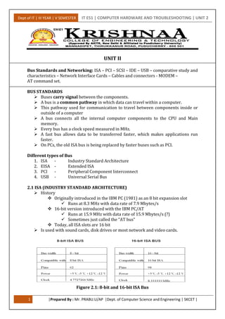
- 1. Dept of IT | III YEAR | V SEMESTER IT E51 | COMPUTER HARDWARE AND TROUBLESHOOTING | UNIT 2 1 |Prepared By : Mr. PRABU.U/AP |Dept. of Computer Science and Engineering | SKCET | UNIT II Bus Standards and Networking: ISA – PCI – SCSI – IDE – USB – comparative study and characteristics – Network Interface Cards – Cables and connectors - MODEM – AT command set. BUS STANDARDS Buses carry signal between the components. A bus is a common pathway in which data can travel within a computer. This pathway used for communication to travel between components inside or outside of a computer A bus connects all the internal computer components to the CPU and Main memory. Every bus has a clock speed measured in MHz. A fast bus allows data to be transferred faster, which makes applications run faster. On PCs, the old ISA bus is being replaced by faster buses such as PCI. Different types of Bus 1. ISA - Industry Standard Architecture 2. EISA - Extended ISA 3. PCI - Peripheral Component Interconnect 4. USB - Universal Serial Bus 2.1 ISA (INDUSTRY STANDARD ARCHITECTURE) History Originally introduced in the IBM PC (1981) as an 8 bit expansion slot Runs at 8.3 MHz with data rate of 7.9 Mbytes/s 16-bit version introduced with the IBM PC/AT Runs at 15.9 MHz with data rate of 15.9 Mbytes/s (?) Sometimes just called the “AT bus” Today, all ISA slots are 16 bit Is used with sound cards, disk drives or most network and video cards. Figure 2.1: 8-bit and 16-bit ISA Bus
- 2. Dept of IT | III YEAR | V SEMESTER IT E51 | COMPUTER HARDWARE AND TROUBLESHOOTING | UNIT 2 2 |Prepared By : Mr. PRABU.U/AP |Dept. of Computer Science and Engineering | SKCET | 1. ISA Bus Architecture The BUS is divided into two sides. The first side pins are named A1 to A31 and it is the components side. It consists of the address and data buses. The second side pins are named B1 to B31 and it is the solder side. This side contents the power pins and the signals related to interrupts and DMA transfers. Figure 2.2 ISA Bus Architecture 2. EISA Bus The Extended Industry Standard Architecture is a bus standard for IBM compatible computers. EISA buses are 32 bits wide and support multiprocessing. 3. Uses Just about any peripheral (sound cards, disk drives, etc.) PnP ISA In 1993, Intel and Microsoft introduced “PnP ISA”, for plug-and-play ISA Allows the operating system to configure expansion boards automatically Form factor Large connector in two segments Smaller segment is the 8-bit interface (36 signals) Larger segment is for the 16-bit expansion (62 signals) 8-bit cards only use the smaller segment 4. Advancements EISA Extended ISA Design by nine IBM competitors (AST, Compaq, Epson, HP, NEC, Olivetti, Tandy, WYSE, Zenith) Intended to compete with IBM’s MCA EISA is hardware compatible with ISA MCA Micro Channel Architecture Introduced by IBM in 1987 as a replacement for the AT/ISA bus EISA and MCA have not been successful!
- 3. Dept of IT | III YEAR | V SEMESTER IT E51 | COMPUTER HARDWARE AND TROUBLESHOOTING | UNIT 2 3 |Prepared By : Mr. PRABU.U/AP |Dept. of Computer Science and Engineering | SKCET | 2.2 PCI (PERIPHERAL COMPONENT INTERCONNECT) A computer bus is used to transfer data from one location or device on the motherboard to the central processing unit where all calculations take place. Two different parts of a Bus Address bus-transfers information about where the data should go Data bus-transfers the actual data 1. History PCI(Peripheral Component Interconnect) bus is based on ISA (Industry Standard Architecture) Bus and VL (VESA Local) Bus. Introduced by Intel in 1992 Revised twice into version 2.1 which is the 64-bit standard that it is today. PCI provides direct access to system memory for the devices that are connected to the bus which is then connected through a bridge that connects to the front side bus. This configuration allowed for higher performance without slowing down the processor Most modern PCs include a PCI bus PCI is an interconnection system between a microprocessor and attached devices in which expansion slots are spaced closely for high speed operation. PCI transmits 32 bits at a time in a 124-pin connection (the extra pins are for power supply and grounding) and 64 bits in a 188-pin connection in an expanded implementation. The advantage of a bus is that it makes parts more interchangeable. The 32-bit PCI bus has a maximum speed of 33 MHz, which allows a maximum of 133 MB of data to pass through the bus per second In servers you have a special 64-bit 66MHz PCI slots that can accept special high-speed cards, from 512 MB to 1 GB of data per second. 2. PCI System Bus Performance What makes the PCI bus one of the fastest I/O bus used today? Three features make this possible: Burst Mode: allows multiple sets of data to be sent Full Bus Mastering: the ability of devices on the PCI bus to perform transfers directly High Bandwidth Options: allows for increased speed of the PCI “Plug and Play” utilized the PCI bus concept. 3. Plug and Play Requirements for full implementation: Plug and Play BIOS Extended System Configuration Data (ESCD) Plug and Play operating system Tasks it automates: Interrupt Requests (IRQ) Direct Memory Access (DMA) Memory Addresses Input/Output (I/O) Configuration
- 4. Dept of IT | III YEAR | V SEMESTER IT E51 | COMPUTER HARDWARE AND TROUBLESHOOTING | UNIT 2 4 |Prepared By : Mr. PRABU.U/AP |Dept. of Computer Science and Engineering | SKCET | 4. How PCI Works: Installing a New Device Once a new device has been inserted into a PCI slot on the motherboard 1. Operating System Basic Input/Output System (BIOS) initiates Plug and Play (PnP) BIOS. 2. PnP BIOS scans the PCI bus for any new hardware connected to the bus. If new hardware is found, it will ask for identification. 3. The device will respond with its identification and send its device ID to the BIOS through the bus. 4. PnP checks the Extended System Configuration Data (ESCD) to make sure the configuration data already exists for the card. (If the card is new, then there will be no data for it.) 5. PnP will assign an Interrupt Request Line, Direct Memory Access, memory address and Input/Output settings to the card, then stores the information in the ESCD. 6. When the Windows software loads, it will check the PCI bus and the ESCD to see if there is new hardware. Windows will alert the user that new hardware has been found if there is new hardware installed and will also identify the hardware. 7. Windows will determine the device and attempt to install its driver. The operating system may ask the user to insert a disk containing the driver or direct it to where the driver is located. In the event that Windows is unable to determine what the device is, it will provide a dialog window so the user can identify the hardware and load its driver. 2.3 SCSI (SMALL COMPUTER SYSTEM INTERFACE) SCSI is a computer bus interface standard for attaching different kinds of peripherals to interface with the host computer by means of a SCSI-bus cable. SCSI is used to interface to a number of different device types, such as Hard Drives, Tape Backups, CD-ROM drives, Printers, Scanners, etc. Developed by the American National Standards Institute (ANSI) SCSI is Pronounced "scuzzy" Supported by all major operating systems. 1. Version: The first version (SCSI-1), adopted by ANSI in 1986, was an 8-bit version with a 5 MBps transfer speed that allowed up to eight devices to be connected with a maximum cable length of six meters. SCSI-2: 8-bit bus, six meter cable length, 5-10 MBps; connects 8 or 16 devices. 50-pin connector. SCSI-3: The latest version, 16-bit Ultra-640 (Fast-320) SCSI, was introduced in 2003 and has a 640 MBps transfer speed, connecting up to 16 devices with a 12 meter cable length. The SCSI Clock can be 5 , 10, 20, or 40 MHz SCSI bus clock 8-bit (50 pin) 16-bit (68 pin) 5 MHz (SCSI 1) 2-5 MBytes/s N/A 10 MHz (Fast SCSI) 10 MByte/s 20 MByte/s 20 MHz (Fast-20, Ultra SCSI) 20 MByte/s 40 MByte/s 40 MHz (Fast-40, Ultra-2) 40 MByte/s 80 MByte/s
- 5. Dept of IT | III YEAR | V SEMESTER IT E51 | COMPUTER HARDWARE AND TROUBLESHOOTING | UNIT 2 5 |Prepared By : Mr. PRABU.U/AP |Dept. of Computer Science and Engineering | SKCET | 2. SCSI 10 Control Signals: 1. RST—the reset signal activates to bring all devices with SCSI controller to start up state. 2. SEL—when bus is used for selecting an SCSI target the SCSI controller examines SCSI ID and always select the highest ID device 3. BSY (for Busy)—when SCSI bus is not available to other device (controller) 4. ATN—activates when a device draws attention before sending a message to a target 5. REQ— requests a data transfer by a device with the SCSI controller 6. ACK—acknowledgement from the SCSI controller that data transfer completes 7. MSG—when a message or information is being transferred through the SCSI bus 8. C/D—1 or 0 when a control (command or status) or data word is being transferred, respectively 9. I/O—1 or 0 when a data is input to SCSI controller or output from the controller, respectively 10. Parity — check bit, checking whether data has been lost or written 3. Sequences of SCSI Signals Sequence 0: Arbitration when Busy is not active Sequence 1: Selection using SEL—the selection of signals is done Sequence 2: Command or status or data transfer Sequence 3: Reselection 4. SCSI controller arbitration policy Access to highest priority device first Advantage that it is easy to decide which device gets access to the bus 5. Disadvantage Starvation problem Starvation when a device with a high SCSI ID can prevent a device with a lower ID from ever getting a chance to use the bus by making repeated requests for the bus 2.4 IDE (INTEGRATED DRIVE ELECTRONICS) IDE also stands for integrated development environment. IDE is a standard electronic interface used between a computer motherboard's data paths or bus and the computer's disk storage devices. The IDE interface is based on the IBM PC Industry Standard Architecture (ISA) 16-bit bus standard. IDE was adopted as a standard by American National Standards Institute (ANSI) in November, 1990. The ANSI name for IDE is Advanced Technology Attachment (ATA). The drive can connect directly to the motherboard or controller. The original IDE had a 16-bit interface that connected two devices to a single- ribbon cable. IDE’s development increased data transfer rate (DTR) speed and reduced storage device and controller issues. The primary interface used to connect a hard disk drive to a PC transmit and receive data to and from the drive
- 6. Dept of IT | III YEAR | V SEMESTER IT E51 | COMPUTER HARDWARE AND TROUBLESHOOTING | UNIT 2 6 |Prepared By : Mr. PRABU.U/AP |Dept. of Computer Science and Engineering | SKCET | IDE allows one master and one slave for each IDE connector on the motherboard. IDE costs less than SCSI. Motherboard Primary Slave Secondary Master IDE Drives Secondary Slave Primary Master Figure 2.3: IDE Drives 1. IDE Cable Structure: Figure 2.4: IDE Cable Structure Programmed Input/Output (PIO) a method of transferring data between two devices ATA uses PIO and defines the speed of the data transfer in terms of the PIO mode. PIO Mode Data transfer (MBps) Standard 0 3.3 ATA 1 5.2 ATA 2 8.3 ATA 3 11.1 ATA - 2 4 16.6 ATA - 2 2. Version: There are several versions of ATA: ATA: supports one or two hard drives, a 16-bit interface and PIO modes 0, 1& 2. ATA-2: Supports faster PIO modes (3 and 4) and ATA-3: Minor revision to ATA-2. Ultra-ATA: running at 33 MBps. ATA/66: throughput to 66 MBps. ATA/100: Data transfer rates to 100 MBps.
- 7. Dept of IT | III YEAR | V SEMESTER IT E51 | COMPUTER HARDWARE AND TROUBLESHOOTING | UNIT 2 7 |Prepared By : Mr. PRABU.U/AP |Dept. of Computer Science and Engineering | SKCET | 3. PIN details PIN NO PIN DETAILS 1 Reset 2,19,22,24,26,30,40 Ground 3 TO 18 DATA 1 TO 15 23 I/O write 25 I/O read 28 Cable select 33 Addr 1 35 Addr 0 36 Addr 2 2.5 USB (UNIVERSAL SERIAL BUS) Universal Serial Bus, USB is a standard that was introduced in 1995 by Intel, Compaq, Microsoft and other computer companies. Universal Serial Bus (USB) connects between a computer and peripheral devices including a mobile phone and a desktop computer. The connection is made by a cable that has a connector at either end. Data transferring application Two-way communication USB cables also carry an electric charge that can be used to power peripherals (such as USB mice or keyboards), and many mobile phones can be charged through their USB port. USB 1.x is an external bus standard that supports data transfer rates of 12 Mbps USB is capable of supporting up to 127 peripheral devices. USB 2.0, also known as hi-speed USB, was developed by Compaq, Intel, Microsoft, Philips was introduced in 2001. It is capable of supporting a transfer rate of up to 480 Mbps. In 2012, USB 3.0 also known as Super Speed USB is the latest version of the USB protocol. Most new computers feature USB 3.0 ports built-in, offering data transfer speeds of up to five gigabits per second. USB 3.0 revision for improved performance and speed, including USB thumb drives, digital cameras, external hard drives, MP3 players, and other devices. 1. USB devices Today, there are millions of different USB devices that can be connected to your computer. Camera, External drive, iPod or other MP3 player, Keyboard, Microphone, Mouse, Printer, Scanner, Smartphone, Tablet, Webcams
- 8. Dept of IT | III YEAR | V SEMESTER IT E51 | COMPUTER HARDWARE AND TROUBLESHOOTING | UNIT 2 8 |Prepared By : Mr. PRABU.U/AP |Dept. of Computer Science and Engineering | SKCET | 2. USB connector variations USB connectors come in many shapes and sizes as there are many different devices that utilize them. Every version of USB connector including standard, Mini, and Micro. 3. USB Device Basics – The Protocol USB protocol defines a set of standards that any device can follow No need to write a driver for a device that is in a predefined class and follows that standard, Predefined classes: storage devices, keyboards, mice, joysticks, network devices, and modems No defined standard for video devices and USB-to-serial devices Providing plug and play capabilities 4. Endpoints The most basic form of USB communication is through an endpoint Carries data in one direction From the host to device (OUT endpoint) From the device to the host (IN endpoint) 5. Benefits for Users Ease of Use Ease of use was a major design goal for USB, and the result is an interface that’s a pleasure to use for many reasons One interface for many devices USB is versatile enough to be usable with many kinds of peripherals. Instead of having a different connector type and supporting hardware for each peripheral, one interface serves many. Automatic configuration When a user connects a USB peripheral to a computer, its OS automatically detects the peripheral and loads the appropriate software driver. Hot pluggable We can connect and disconnect a peripheral whenever you want, whether or not the system and peripheral are powered, without damaging the PC or peripheral. The operating system detects when a device is attached and readies it for use. 2.6 COMPARATIVE STUDY AND CHARACTERISTICS 1) ISA (Industry Standard Architecture) bus: ISA bus was created by IBM in 1981. ISA bus can transfer 8 or 16 bits at one time. ISA 8 bit bus can run at 4.77 MHz and 16 bit at 8.33 MHz.
- 9. Dept of IT | III YEAR | V SEMESTER IT E51 | COMPUTER HARDWARE AND TROUBLESHOOTING | UNIT 2 9 |Prepared By : Mr. PRABU.U/AP |Dept. of Computer Science and Engineering | SKCET | 2) PCI (Peripheral Component Interconnect) bus: PCI bus was created by Intel in 1993. PCI bus can transfer 32 or 64 bits at one time. PCI bus can run at 33 Mhz. 3) IDE (Integrated Drive Electronics) bus: IDE bus is used for connecting disks and CDROMs to the computer. 4) USB (Universal Serial Bus): It is used for connecting keyboard and mouse, and other USB devices to the computer. A USB bus has a connector with four wires. Two wires are used for supplying electrical power to the USB devices. USB 1.0 has a data rate of 1.5 MB/s and USB 2.0 which is a high speed one has a data rate of 35 MB/s. 5) SCSI (Small Computer System Interface) bus: It is a high performance bus which is used for fast disks, scanners, and for devices which require high bandwidth. It has a data rate of 160 MB/s. Comparative Study SCSI is better than IDE IDE is cheaper than SCSI SCSI is faster than IDE Slow IDE devices also slow down other devices How to calculate your bus "saturation" SCSI is multithreaded, IDE is not SCSI needs only single IRQ, IDE needs two 2.7 NIC (NETWORK INTERFACE CARDS) A network interface card (NIC) is a computer circuit board or card that is installed in a computer so that it can be connected to a network. It is a full-time connection to a network. To exchange information with other computers and the Internet. The NIC contains the electronic circuitry required to communicate using a wired connection (e.g., Ethernet) or a wireless connection (e.g., WiFi). You need it to use e-mail, access information on the Internet, share documents within a corporate network. 1. History of NIC In 1973 Robert Metcalfe needed something that was fast, could connect hundreds of computers. To solve this problem, Metcalfe developed Ethernet. The original Ethernet sent roughly a paragraph of data over thick coaxial cable and could handle a distance of one kilometer. 2. Ethernet Connection Ethernet is really a standard for computer network technologies that describes both the hardware and the communication protocols. Ethernet was commercially introduced in 1980 and has largely replaced other wired network technologies. Since Ethernet is so widely used, most modern computers have a NIC built into the motherboard.
- 10. Dept of IT | III YEAR | V SEMESTER IT E51 | COMPUTER HARDWARE AND TROUBLESHOOTING | UNIT 2 10 |Prepared By : Mr. PRABU.U/AP |Dept. of Computer Science and Engineering | SKCET | A separate network card is not required, unless some other type of network is used. An Ethernet connection uses a standard interface known as a RJ45 connector. RJ stands for registered jack. The figure below shows an Ethernet cable with a RJ45 connector. Smalls LED lights built into the connection will show that a connection is active and whether data is being transferred. All NICs feature a speed rating such as 11 Mbps, 54 Mbps or 100 Mbps that suggest the general performance of the unit. These cards typically use an Ethernet connection and are available in 10, 100, and 1000 Base-T configurations. A 100 Base-T card can transfer data at 100 Mbps. 3. Twisted Pair Cable Connect to networking devices such as network interface cards and switches using RJ45 connectors. One end must connect to a host, the other to a networking device such as a switch. Figure 2.5: Twisted Pair Cable 4. Network Cards Convert Data from Parallel to Serial, and vice versa Most computers use parallel data lines internally to send data between the CPU and the adapter cards. This is called a Bus. Most networking media transmit data in a single line, called serial transmission. The NIC translates parallel into serial for outgoing messages and serial into parallel for incoming messages. Prior to the invention of NICs, data was sent via serial ports on the computer. 5. How the NIC transfers data The app you are using generates the data you would like to send to another computer. Your NIC accepts the data from your motherboard and transfers it to a small buffer on the card. The NIC adds its address (set by the manufacturer) plus the destination address and the type of data to the buffer. Your NIC calculates the checksum, or CRC, for the data in the buffer. The data is arranged into a packet and sent over the network. If there are no errors, the receiving station acknowledges the received data.
- 11. Dept of IT | III YEAR | V SEMESTER IT E51 | COMPUTER HARDWARE AND TROUBLESHOOTING | UNIT 2 11 |Prepared By : Mr. PRABU.U/AP |Dept. of Computer Science and Engineering | SKCET | 2.8 CABLES AND CONNECTORS 1. VGA (Video Graphics Array) In 1980. VGA cable used to connect a computer to a monitor. VGA connections can be identified by 15 pins arranged in 3 rows with 5 on each row. Each row corresponds to the 3 different color channels used in display: red, green, and blue. 2. DVI (Digital Visual Interface) DVI became successor to VGA as technology moved away from analog towards digital. DVI connectors come in 3 varieties. DVI-A can transmit analog signals, (useful for CRT monitors and LCDs of lower quality). DVI-D can transmit the newer digital signals. DVI-I is capable of both analog and digital. 3. HDMI (High Definition Multimedia Interface) High-definition broadcasts means high quality HDMI sends both video and audio signals together. HDMI connectors come in 4 types: Type A is the most popular. It is 19 pins on the male head. Type A is compatible with single-link DVI-D connections. Type B is larger than Type A, coming in at 29 pins on the male head. Type B is compatible with dual-link DVI-D connections. Type C is a 19-pin connector that’s most often used with portable devices, like camcorders and digital cameras. Type D looks similar to a micro-USB cord. It also has 19 pins. 4. USB (Universal Serial Bus) Micro USB, mini USB, type B standard USB, and type A standard USB keyboards, mice, headsets, flash drives, wireless adapters, etc. — can be connected to your computer through a USB port. USB 1.0/1.1 can transmit data at speeds up to 12 Mbps. USB 2.0 can transmit data at speeds up to 480 Mbps. USB 3.0 can transmit data at speeds up to 4.8 Gbps. 5. IDE (Integrated Drive Electronics) IDE cables were used to connect storage devices to a motherboard. Cable that looks like a ribbon with more than 2 plugs. IDE cable have 40 pins 6. SATA (Serial Advanced Technology Attachment) Newer hard drives will likely use SATA ports over IDE ports. SATA provides higher data transfer speeds. SATA cable can be identified by two connectors, each having 7 pins
- 12. Dept of IT | III YEAR | V SEMESTER IT E51 | COMPUTER HARDWARE AND TROUBLESHOOTING | UNIT 2 12 |Prepared By : Mr. PRABU.U/AP |Dept. of Computer Science and Engineering | SKCET | 7. eSATA (External Serial Advanced Technology Attachment) extension of SATA cable allows connections to devices like external hard drives and optical drives. offers speeds much faster 8. FireWire FireWire is similar to that of USB high speed data transfer High bandwidth devices, like printers and scanners, will benefit from FireWire. FireWire cables come in two forms: 1394a (which has a transfer speed of 400 Mbps) and 1394b (which has a transfer speed of 800 Mbps). 9. Ethernet Ethernet cables are used to set up local area networks. three varieties Cat 5 cables are the most basic type and provide speeds of either 10 Mbps or 100 Mbps. Cat 5e, which means Cat 5 Enhanced, allows for faster data transmission. It caps at 1,000 Mbps. Cat 6 is the latest and offers the best performance of the three. It’s capable of supporting 10 Gbps speeds. 10.Video Connectors: RCA The RCA connector is used for video and audio signals. yellow, white, red. 11.Power Cables An assembly of two or more electrical conductors usually held together with an overall sheath. The assembly is used for transmission of electrical power. 2.9 MODEM Modem (modulator-demodulator) It is a device that modulates signals to encode digital information and demodulates signals to decode the transmitted information. A modem is a device or program that enables a computer to transmit data over, for example, telephone or cable lines. Computer information is stored digitally, whereas information transmitted over telephone lines is transmitted in the form of analog waves
- 13. Dept of IT | III YEAR | V SEMESTER IT E51 | COMPUTER HARDWARE AND TROUBLESHOOTING | UNIT 2 13 |Prepared By : Mr. PRABU.U/AP |Dept. of Computer Science and Engineering | SKCET | One computer's modem converts its digital signals (which cannot be sent efficiently over phone lines) into analog signals (which can be). The other computer's modem reconverts the analog signals (that the computer cannot understand) into digital signals (that it can). Conversion of one type of signals to another is called modulation; their reconversion to the original type is called demodulation. Bits per second (bps) used for measurement Modern work at 56 thousand bits per second (Kbps) The Modem is a hardware device that enables a computer to send and receive information over telephone lines by converting the digital data used by your computer into an analog signal used on phone lines and then converting it back once received on the other end. There is one standard interface for connecting external modems to computers called RS-232. Modems are referred to as an asynchronous device Transmits data in an intermittent stream of small packets. In asynchronous communication, 1 byte (8 bits) is transferred within 1 packet, which is equivalent to one character. For the computer to receive this information, each packet must contain a Start and a Stop bit; 1. Types of computer modems Internal modem that connects to a PCI slot inside a newer desktop computer or ISA slot on an older computer. The Internal Modem shown at the beginning of this document is an example of a PCI modem. External modem is located within a box and is hooked up externally to the computer, usually the Serial Ports or USB port. Removable modem that is used with older laptops PCMCIA slot and is removed when you need the PCMCIA slot for another device, but are not planning on using the modem. 2. Mode of Transmission Transmission mode means transferring of data between two devices. the types are (i) Data flow (ii) Physical connection (iii) Timing (i) Data Flow a. Simplex transmission Data can be send only through one direction. We cannot send a message back to the sender. Eg: loudspeaker, Television broadcasting, television and remote , keyboard and monitor.
- 14. Dept of IT | III YEAR | V SEMESTER IT E51 | COMPUTER HARDWARE AND TROUBLESHOOTING | UNIT 2 14 |Prepared By : Mr. PRABU.U/AP |Dept. of Computer Science and Engineering | SKCET | Figure 2.6: Simplex transmission b. Half-duplex (HDX) transmission We can send data in both direction, but it is done one at a time Eg: walkie-talkie Figure 2.7: Half-duplex transmission c. Full-duplex (FDX) transmission We can send data in both directions as it is bidirectional. Data can be sending in both directions simultaneously. Eg: telephone network. Communication between two person in which both can talk and listen at the same time. Figure 2.8: Full-duplex transmission 3. Physical Connection Parallel transmission Fast Simple Line cost Serial transmission Complicated transmitter and receive Decomposing and reconstructing 4. Timing Asynchronous transmission does not need clock signal between the sender and the receiver slower data transfer rate Simple, inexpensive, slow speed transmission Synchronous transmission supports high data transfer rate needs clock signal between the sender and the receiver requires master/slave configuration
- 15. Dept of IT | III YEAR | V SEMESTER IT E51 | COMPUTER HARDWARE AND TROUBLESHOOTING | UNIT 2 15 |Prepared By : Mr. PRABU.U/AP |Dept. of Computer Science and Engineering | SKCET | 2.10 AT COMMAND SET AT commands are used to control MODEMs. AT is the abbreviation for Attention. These commands come from Hayes commands. Developed by Dennis Hayes in 1980 The dial up and wireless MODEMs need AT commands to interact with a computer. Commands used for operations such as dialing, hanging up, and changing the parameters of the connection. Many of the commands that are used to control wired dial-up modems. Such as ATD (Dial), ATA (Answer), ATH (Hook control) and ATO (Return to online data state), Also supported by GSM/GPRS modems and mobile phones. AT commands with a GSM/GPRS MODEM or mobile phone can be used to access following information and services: 1. Information and configuration related to mobile device or MODEM and SIM card. 2. SMS services. 3. MMS services. 4. Fax services. 5. Data and Voice link over mobile network. Get basic information about the mobile phone or GSM/GPRS modem. For example, name of manufacturer (AT+CGMI), model number (AT+CGMM), IMEI number (International Mobile Equipment Identity) (AT+CGSN) and software version (AT+CGMR). Note that mobile phone manufacturers usually do not implement all AT commands 1. Rules A command string should start with "AT" or "at", except for the commands "A/" and "+++". Several commands can be given in one command string. The commands can be given in upper or lower case. A command string should contain less than 40 characters 1 2 3 4 5 6 7 8 9 * = , ; # + > 1 or 0 start bits, 7 or 8 data bits, no, odd or even parity and 1 or 2 stop bits. 2. Execution of commands: Put the modem into command mode The user enters three +++ symbols and the modem responds with "OK". The user then enters ATCH and presses return. The modem responds back by displaying the current channel "C". The user then enters ATCHD to change the channel to D. The modem responds with "OK" after the channel is then set to D.
- 16. Dept of IT | III YEAR | V SEMESTER IT E51 | COMPUTER HARDWARE AND TROUBLESHOOTING | UNIT 2 16 |Prepared By : Mr. PRABU.U/AP |Dept. of Computer Science and Engineering | SKCET | The user can then verify the channel change by typing ATCH and pressing return. Figure 2.9: Execution of commands 3. Two Modes Data mode in which the modem sends the data to the remote modem. A modem in data mode treats everything it receives from the computer as data and sends it across the phone line. Command mode in which data is interpreted as commands to the local modem Commands that the local modem should execute. 4. Hayes Command divided into four groups Basic Command Set - capital character followed by a digit. Extended Command Set - “&” (ampersand) and a capital character followed by a digit. Proprietary Command Set - Usually started by either a backslash (“”), or a percent sign (“%”) Register Commands - Sr=n where r is the number of the register to be changed, and n is the new value that is assigned. 5. Some commands AT - Tells the modem that must begin each line of commands. Z - Resets the modem to its default state. , (a comma) - Makes the software pause for a second. For example, ",,,," tells the software to pause four seconds. ^M - Sends the terminating Carriage Return character to the modem. ; (a semi-colon) - Return to command mode immediately after dialing. W - wait for dial tone. ! - flash hook. put quickly the modem on/off hook.