SlideShare a Scribd company logo
1 of 47
Mohd. Hanif Dewan, Chief Engineer and
Maritime Lecturer & Trainer, Bangladesh.
Read & Understand
The Electrical Diagram
7/10/2014 1
Mohd. Hanif Dewan, Chief Engineer and
Maritime Lecturer & Trainer, Bangladesh.
10. Read & understand the electrical diagrams
Electrical ladder drawings are still one of the common and reliable tools
used to troubleshoot equipment when it fails. As with any good
troubleshooting tool, one must be familiar with its basic features to make
the most of the diagram in the field. In other words, possessing a basic
understanding of how the drawing is laid out — as well as the meaning of
numbers and symbols found on the schematic — will make you that
much more seasoned as a maintenance professional.
There are typically two distinct parts of a ladder drawing:
I. The power component:
The power portion consists of items such as the motor, motor starter
contacts and overloads, disconnect(s), and protective devices (fuses and
circuit breakers).
II. The control component:
The control part encompasses items that make the power components
do their work. For this discussion, we'll focus on the control portion of the
drawing. Let's take a look at the most common components.
7/10/2014 2
Mohd. Hanif Dewan, Chief Engineer and
Maritime Lecturer & Trainer, Bangladesh.
Fig: A sampling of common symbols
you’ll find on the majority of ladder
drawings. The normally open and
normally closed symbols are added
here to merely serve as an
instructional aid.
Symbols. The symbols
that go into making a
ladder drawing are the
ABCs of print reading
(Fig). For instance, in an
air compressor system
there will be a symbol for a
pressure switch. If the
person doing the
troubleshooting and repair
does not recognize that
symbol, it will be difficult to
locate the switch to
determine whether or not it
is working properly.
7/10/2014 3
Mohd. Hanif Dewan, Chief Engineer and
Maritime Lecturer & Trainer, Bangladesh.
Normally Open (NO) and Normally Close (NC):
Many times, the input devices are said to be either normally
open (NO) or normally closed (NC). The normally open or closed
status refers to the shelf state of the device. If a device is
normally open, a resistance check of the device with a digital
multimeter will give a reading of O.L. If the device is normally
closed, a resistance check will give a reading of 0.0.
The normally open and normally closed state of the devices is
not labeled on the ladder drawing. Rather, you must recognize
the symbol. A helpful hint in trying to determine whether the
contacts are open or closed is to think of them in terms of
gravity. If gravity is acting on the device, its normal state is as
shown in the drawing. An exception to this concept is found in
devices that contain springs.
For instance, in the drawing of a normally open pushbutton, it
appears that the pushbutton should be falling down and closing.
However, there is a spring in the pushbutton that holds the
contacts in the open (up) position.
7/10/2014 4
Mohd. Hanif Dewan, Chief Engineer and
Maritime Lecturer & Trainer, Bangladesh.
Rails:
The drawing is called a ladder drawing because it resembles a ladder
in the way it is constructed and presented on the paper. The two
vertical lines (wires) that serve as a boundary for the control system
and deliver the control voltage to the devices are called the rails. The
rails may have overcurrent devices in them (fuses and/or circuit
breakers) and may have contacts from control devices. These control
lines may be thicker than the others to help better identify them. Like a
real ladder, the rails are the supports for the rungs.
If the ladder drawing runs across several pages, the control voltage is
carried from one page to the next along the rails. There are a number of
ways that this may be represented on the drawing. One way this is
done is with the use of continuation arrows at the bottom of the first
page, which indicates that the rails continue on to another page. The
page number on which the rails continue should be noted. On the page
where the rails continue, there are also continuation arrows with the
page number notation from which the control voltage lines originated.
7/10/2014 5
Mohd. Hanif Dewan, Chief Engineer and
Maritime Lecturer & Trainer, Bangladesh.
Fig. 2. In this circuit arrangement, the sequence of events could
be described as such. When the pushbutton (PB) is pressed
down, the circuit is completed and current will flow to energize
the coil (CR1).
Fig. 2. In this circuit arrangement, the sequence of events could
be described as such. When the pushbutton (PB) is pressed
down, the circuit is completed and current will flow to energize
the coil (CR1).
Rungs:
The rungs of the ladder are made up of wires and input devices that
either allow current flow or interrupt current flow to the output devices.
These lines may be thin lines when compared to the lines of the rails.
From the placement of the input and output devices, you can
determine the sequence of events that either energize or de-energize
the outputs. The key to good troubleshooting is determining this
sequence of events. Input devices are typically placed on the left side
of the rungs, while the output devices are placed on the right (Fig. 2).7/10/2014 6
Mohd. Hanif Dewan, Chief Engineer and
Maritime Lecturer & Trainer, Bangladesh.
Placement of input devices:
The input devices are placed on the rungs in a way that
indicates the current flow through the rung when there is a
complete path to the outputs. There are several ways in
which these input devices can be placed on the rungs,
although as stated earlier, they are typically placed on the
left side.
The STOP input devices are typically normally closed and
are placed in series on the rung. This means that they are
placed end to end in the drawing. In order for the current to
flow through them, they must be in the closed position.
Typical STOP input devices include components such as
normally closed pushbuttons and mushroom head buttons,
limit switches, and contacts for light curtains, photocells,
and proximity switches.
7/10/2014 7
Mohd. Hanif Dewan, Chief Engineer and
Maritime Lecturer & Trainer, Bangladesh.
The START input devices are typically normally open and are
usually placed in series with and after the STOP devices. If there
is more than one START device, it is usually placed in parallel with
the others.
When the STOP and START devices are placed in order on the
rung, the flow of current to the output devices can be seen.
Understanding this flow is a great aide in troubleshooting. A key
question to always ask yourself is: “What does it take to energize
the output?”
Fig. 3. This circuit arrangement uses all three types of
logic functions: AND, OR, and AND/OR.
Fig. 3. This circuit arrangement uses all three types of
logic functions: AND, OR, and AND/OR.
7/10/2014 8
Mohd. Hanif Dewan, Chief Engineer and
Maritime Lecturer & Trainer, Bangladesh.
Here's a simple example to analyze. In Fig. 3, what does it
take to energize the output CR1? When either start
pushbutton is depressed, the path is complete, and the coil
of CR1 is energized. In following the path for the current,
you can see the logic of the placement of the input devices.
This logic determines the decision making process of the
input devices and the path for current as it travels to
energize the outputs.
Logic statements:
There are several logic statements that can be used in
placing the input devices in the rungs. The most common of
these are the AND, the OR, and the combination AND/OR
function. In Fig. 3, all three are present.
1. The end-to-end placement of the stop and start
pushbuttons makes an AND logic statement. In other
words, both the stop AND the start buttons must be used to
energize the coil.7/10/2014 9
Mohd. Hanif Dewan, Chief Engineer and
Maritime Lecturer & Trainer, Bangladesh.
2. The parallel placements of the start buttons makes an OR
logic statement. Either start pushbutton will complete the path
and energize the coil.
3. Placing the stop pushbutton in series with the parallel start
pushbuttons supports the AND/OR logic statement.
Placement of the output devices. As noted earlier, the output
devices are placed on the right side of the ladder drawing.
Unlike input devices, it's important that the output devices only
be placed in parallel. If they are placed in series, electrical
theory says that the voltage will drop across the resistance of
each output. If this happens, they will not operate properly.
Outputs include items such as lights, coils, solenoids, and
heating elements. In addition to the commonly accepted
symbols shown in Fig. 1, letters and numbers also help to
identify the output devices.
7/10/2014 10
Mohd. Hanif Dewan, Chief Engineer and
Maritime Lecturer & Trainer, Bangladesh.
Fig. 4. As noted by the numbers on the right rail, this circuit
arrangement indicates there is a normally open contact in
Rung 2 and a normally closed contact in Rung 3.
Fig. 4. As noted by the numbers on the right rail, this circuit
arrangement indicates there is a normally open contact in
Rung 2 and a normally closed contact in Rung 3.
Coils will typically have contacts associated with them. These
contacts will change state when the coil is energized. The changing
contacts will either complete or open the path for current.
As noted in Fig. 4, when the pushbutton is pressed down, the path
is completed, and current will flow to energize the coil. When the
coil is energized, the contacts associated with the coil will change
state. The red light will go on, and the green light will go off.
7/10/2014 11
Mohd. Hanif Dewan, Chief Engineer and
Maritime Lecturer & Trainer, Bangladesh.
Locating the contacts:
In the ladder drawing, the contacts associated with the
coil can be located using a cross-reference system. The
rungs are usually numbered on the left side of the rail. A
number on the right side of the rail references the
contacts associated with the coil (Fig. 4). These numbers
are the rungs in which the contacts can be found. A
number without a line under it references an open
contact. Drawing a line under the number on the right rail
references a closed contact.
Let us see a teaching video for “Reading Electrical
Diagram”
7/10/2014 12
Mohd. Hanif Dewan, Chief Engineer and
Maritime Lecturer & Trainer, Bangladesh.
“How to read an Electrical Diagram”
7/10/2014
Mohd. Hanif Dewan, Chief Engineer and
Maritime Lecturer & Trainer, Bangladesh.
13
Reference:
1. www.realfixerrealfast.com
7/10/2014 14
Mohd. Hanif Dewan, Chief Engineer and
Maritime Lecturer & Trainer, Bangladesh.
7/10/2014 15
Mohd. Hanif Dewan, Chief Engineer and
Maritime Lecturer & Trainer, Bangladesh.
7/10/2014 16
Mohd. Hanif Dewan, Chief Engineer and
Maritime Lecturer & Trainer, Bangladesh.
Wires and connections
Component Circuit Symbol Function of Component
Wire
To pass current very easily from one part of a
circuit to another.
Wires joined
A 'blob' should be drawn where wires are
connected (joined), but it is sometimes omitted.
Wires connected at 'crossroads' should be
staggered slightly to form two T-junctions, as
shown on the right.
Wires not joined
In complex diagrams it is often necessary to
draw wires crossing even though they are not
connected. The simple crossing on the left is
correct but may be misread as a join where the
'blob' has been forgotten. The bridge symbol on
the right leaves no doubt!
Power Supplies
Component Circuit Symbol Function of Component
Cell
Supplies electrical energy.
The larger terminal (on the left) is positive (+).
A single cell is often called a battery, but strictly a battery is
two or more cells joined together.
Battery
Supplies electrical energy. A battery is more than
one cell.
The larger terminal (on the left) is positive (+).
7/10/2014 17
Mohd. Hanif Dewan, Chief Engineer and
Maritime Lecturer & Trainer, Bangladesh.
7/10/2014 18
Mohd. Hanif Dewan, Chief Engineer and
Maritime Lecturer & Trainer, Bangladesh.
7/10/2014 19
Mohd. Hanif Dewan, Chief Engineer and
Maritime Lecturer & Trainer, Bangladesh.
7/10/2014 20
Mohd. Hanif Dewan, Chief Engineer and
Maritime Lecturer & Trainer, Bangladesh.
7/10/2014 21
Mohd. Hanif Dewan, Chief Engineer and
Maritime Lecturer & Trainer, Bangladesh.
7/10/2014 22
Mohd. Hanif Dewan, Chief Engineer and
Maritime Lecturer & Trainer, Bangladesh.
7/10/2014 23
Mohd. Hanif Dewan, Chief Engineer and
Maritime Lecturer & Trainer, Bangladesh.
7/10/2014 24
Mohd. Hanif Dewan, Chief Engineer and
Maritime Lecturer & Trainer, Bangladesh.
7/10/2014 25
Mohd. Hanif Dewan, Chief Engineer and
Maritime Lecturer & Trainer, Bangladesh.
7/10/2014 26
Mohd. Hanif Dewan, Chief Engineer and
Maritime Lecturer & Trainer, Bangladesh.
7/10/2014 27
Mohd. Hanif Dewan, Chief Engineer and
Maritime Lecturer & Trainer, Bangladesh.
7/10/2014 28
Mohd. Hanif Dewan, Chief Engineer and
Maritime Lecturer & Trainer, Bangladesh.
7/10/2014 29
Mohd. Hanif Dewan, Chief Engineer and
Maritime Lecturer & Trainer, Bangladesh.
7/10/2014 30
Mohd. Hanif Dewan, Chief Engineer and
Maritime Lecturer & Trainer, Bangladesh.
7/10/2014 31
Mohd. Hanif Dewan, Chief Engineer and
Maritime Lecturer & Trainer, Bangladesh.
LET’S READ A DIAGRAM
7/10/2014 32
Mohd. Hanif Dewan, Chief Engineer and
Maritime Lecturer & Trainer, Bangladesh.
7/10/2014 33
Mohd. Hanif Dewan, Chief Engineer and
Maritime Lecturer & Trainer, Bangladesh.
7/10/2014 34
Mohd. Hanif Dewan, Chief Engineer and
Maritime Lecturer & Trainer, Bangladesh.
7/10/2014 35
Mohd. Hanif Dewan, Chief Engineer and
Maritime Lecturer & Trainer, Bangladesh.
7/10/2014 36
Mohd. Hanif Dewan, Chief Engineer and
Maritime Lecturer & Trainer, Bangladesh.
7/10/2014 37
Mohd. Hanif Dewan, Chief Engineer and
Maritime Lecturer & Trainer, Bangladesh.
7/10/2014 38
Mohd. Hanif Dewan, Chief Engineer and
Maritime Lecturer & Trainer, Bangladesh.
7/10/2014 39
Mohd. Hanif Dewan, Chief Engineer and
Maritime Lecturer & Trainer, Bangladesh.
7/10/2014 40
Mohd. Hanif Dewan, Chief Engineer and
Maritime Lecturer & Trainer, Bangladesh.
7/10/2014 41
Mohd. Hanif Dewan, Chief Engineer and
Maritime Lecturer & Trainer, Bangladesh.
7/10/2014 42
Mohd. Hanif Dewan, Chief Engineer and
Maritime Lecturer & Trainer, Bangladesh.
7/10/2014 43
Mohd. Hanif Dewan, Chief Engineer and
Maritime Lecturer & Trainer, Bangladesh.
7/10/2014 44
Mohd. Hanif Dewan, Chief Engineer and
Maritime Lecturer & Trainer, Bangladesh.
7/10/2014 45
Mohd. Hanif Dewan, Chief Engineer and
Maritime Lecturer & Trainer, Bangladesh.
7/10/2014 46
Mohd. Hanif Dewan, Chief Engineer and
Maritime Lecturer & Trainer, Bangladesh.
ANY QUESTION?
THANK YOU!
7/10/2014
Mohd. Hanif Dewan, Chief Engineer and
Maritime Lecturer & Trainer, Bangladesh.
47

More Related Content

What's hot

Electrical grounding and earthing systems
Electrical grounding and earthing systemsElectrical grounding and earthing systems
Electrical grounding and earthing systems
Biswajit Pratihari
 
Electrical maintenance-1
Electrical maintenance-1Electrical maintenance-1
Electrical maintenance-1
Vijay Raskar
 

What's hot (20)

Electrical grounding and earthing systems
Electrical grounding and earthing systemsElectrical grounding and earthing systems
Electrical grounding and earthing systems
 
Joints and terminations
Joints and terminationsJoints and terminations
Joints and terminations
 
Distribution boards and Protection devices ppt
Distribution boards and Protection devices  pptDistribution boards and Protection devices  ppt
Distribution boards and Protection devices ppt
 
What is a Contactor?
What is a Contactor?What is a Contactor?
What is a Contactor?
 
Reading of electrical drawing
Reading of electrical drawingReading of electrical drawing
Reading of electrical drawing
 
Relay & Magnetic Contactor.pptx
Relay & Magnetic Contactor.pptxRelay & Magnetic Contactor.pptx
Relay & Magnetic Contactor.pptx
 
Contactor
ContactorContactor
Contactor
 
Presentation on switchgear
Presentation on switchgear Presentation on switchgear
Presentation on switchgear
 
To control one lamp with one switch.
To control one lamp with one switch.To control one lamp with one switch.
To control one lamp with one switch.
 
To control two lamp (in parallel) with one switch
To control two lamp (in parallel) with one switch To control two lamp (in parallel) with one switch
To control two lamp (in parallel) with one switch
 
Circuit protection devices perfect ppt
Circuit protection devices perfect ppt Circuit protection devices perfect ppt
Circuit protection devices perfect ppt
 
Power Transformer Parts And Functions
Power Transformer Parts And FunctionsPower Transformer Parts And Functions
Power Transformer Parts And Functions
 
Types of wiring diagram 22.pptx
Types of wiring diagram 22.pptxTypes of wiring diagram 22.pptx
Types of wiring diagram 22.pptx
 
star delta auto starter with forward reverse and motor protection
star delta auto starter with forward reverse and motor protectionstar delta auto starter with forward reverse and motor protection
star delta auto starter with forward reverse and motor protection
 
Basics of electrical control panel
Basics of electrical control panelBasics of electrical control panel
Basics of electrical control panel
 
Analog and Digital Multimeters
Analog and Digital MultimetersAnalog and Digital Multimeters
Analog and Digital Multimeters
 
Multimeter basics
Multimeter   basicsMultimeter   basics
Multimeter basics
 
Electrical and Electronics lab manual
Electrical and Electronics lab manualElectrical and Electronics lab manual
Electrical and Electronics lab manual
 
Electrical maintenance-1
Electrical maintenance-1Electrical maintenance-1
Electrical maintenance-1
 
Testing of Transformers.
Testing of Transformers.Testing of Transformers.
Testing of Transformers.
 

Viewers also liked

Electrical Drawings and Schematics
Electrical Drawings and SchematicsElectrical Drawings and Schematics
Electrical Drawings and Schematics
Living Online
 
Electrical Drawings and Schematics
Electrical Drawings and SchematicsElectrical Drawings and Schematics
Electrical Drawings and Schematics
Living Online
 

Viewers also liked (9)

AutoCad Electrical
AutoCad ElectricalAutoCad Electrical
AutoCad Electrical
 
Electrical Measurements
Electrical MeasurementsElectrical Measurements
Electrical Measurements
 
Digital Temperature Controllers
Digital Temperature ControllersDigital Temperature Controllers
Digital Temperature Controllers
 
Electrical Control Panels by AKT Industrial Solutions, New Delhi
Electrical Control Panels by AKT Industrial Solutions, New DelhiElectrical Control Panels by AKT Industrial Solutions, New Delhi
Electrical Control Panels by AKT Industrial Solutions, New Delhi
 
Practical Troubleshooting of Electrical Equipment and Control Circuits
Practical Troubleshooting of Electrical Equipment and Control CircuitsPractical Troubleshooting of Electrical Equipment and Control Circuits
Practical Troubleshooting of Electrical Equipment and Control Circuits
 
Chilled water piping basics
Chilled water piping basicsChilled water piping basics
Chilled water piping basics
 
Heat Exchangers by Hanif Dewan
Heat Exchangers by Hanif DewanHeat Exchangers by Hanif Dewan
Heat Exchangers by Hanif Dewan
 
Electrical Drawings and Schematics
Electrical Drawings and SchematicsElectrical Drawings and Schematics
Electrical Drawings and Schematics
 
Electrical Drawings and Schematics
Electrical Drawings and SchematicsElectrical Drawings and Schematics
Electrical Drawings and Schematics
 

Similar to Read and Understand The Electrical Diagram

Ch 2 Ladder Basics 1 Chapter 2 Ladder Basics .docx
     Ch 2 Ladder Basics 1 Chapter 2  Ladder Basics  .docx     Ch 2 Ladder Basics 1 Chapter 2  Ladder Basics  .docx
Ch 2 Ladder Basics 1 Chapter 2 Ladder Basics .docx
hallettfaustina
 
PLC: Métodos y aplicaciones de programación de PLC John R Hackworth and Frede...
PLC: Métodos y aplicaciones de programación de PLC John R Hackworth and Frede...PLC: Métodos y aplicaciones de programación de PLC John R Hackworth and Frede...
PLC: Métodos y aplicaciones de programación de PLC John R Hackworth and Frede...
SANTIAGO PABLO ALBERTO
 
Mw training slide
Mw training slideMw training slide
Mw training slide
dedoyin
 

Similar to Read and Understand The Electrical Diagram (20)

Ch 2 Ladder Basics 1 Chapter 2 Ladder Basics .docx
     Ch 2 Ladder Basics 1 Chapter 2  Ladder Basics  .docx     Ch 2 Ladder Basics 1 Chapter 2  Ladder Basics  .docx
Ch 2 Ladder Basics 1 Chapter 2 Ladder Basics .docx
 
IRJET- Causes, Effects and Solutions of Floating in Microcontrollers
IRJET-  	  Causes, Effects and Solutions of Floating in MicrocontrollersIRJET-  	  Causes, Effects and Solutions of Floating in Microcontrollers
IRJET- Causes, Effects and Solutions of Floating in Microcontrollers
 
PLC: Métodos y aplicaciones de programación de PLC John R Hackworth and Frede...
PLC: Métodos y aplicaciones de programación de PLC John R Hackworth and Frede...PLC: Métodos y aplicaciones de programación de PLC John R Hackworth and Frede...
PLC: Métodos y aplicaciones de programación de PLC John R Hackworth and Frede...
 
Control components - thiết bị điều khiển
Control components - thiết bị điều khiểnControl components - thiết bị điều khiển
Control components - thiết bị điều khiển
 
Master Laptop Repair: Unlock the Secrets of Schematic Learning and Become a S...
Master Laptop Repair: Unlock the Secrets of Schematic Learning and Become a S...Master Laptop Repair: Unlock the Secrets of Schematic Learning and Become a S...
Master Laptop Repair: Unlock the Secrets of Schematic Learning and Become a S...
 
Design and Construction of Movable Bridge using Arduino
Design and Construction of Movable Bridge using ArduinoDesign and Construction of Movable Bridge using Arduino
Design and Construction of Movable Bridge using Arduino
 
Elementary diagrams
Elementary diagramsElementary diagrams
Elementary diagrams
 
TL431 - Shunt Regulator Design Procedures for Secondary.pdf
TL431 - Shunt Regulator Design Procedures for Secondary.pdfTL431 - Shunt Regulator Design Procedures for Secondary.pdf
TL431 - Shunt Regulator Design Procedures for Secondary.pdf
 
ppt.pptx
ppt.pptxppt.pptx
ppt.pptx
 
Mw training slide
Mw training slideMw training slide
Mw training slide
 
Electronz_Chapter_10.pptx
Electronz_Chapter_10.pptxElectronz_Chapter_10.pptx
Electronz_Chapter_10.pptx
 
How to Build Your Own Power Supply
How to Build Your Own Power SupplyHow to Build Your Own Power Supply
How to Build Your Own Power Supply
 
IRJET-Design of Capacitor Less LDO Regulator by using Cascode Compensation Te...
IRJET-Design of Capacitor Less LDO Regulator by using Cascode Compensation Te...IRJET-Design of Capacitor Less LDO Regulator by using Cascode Compensation Te...
IRJET-Design of Capacitor Less LDO Regulator by using Cascode Compensation Te...
 
A high speed low power consumption d flip flop for high speed phase frequency...
A high speed low power consumption d flip flop for high speed phase frequency...A high speed low power consumption d flip flop for high speed phase frequency...
A high speed low power consumption d flip flop for high speed phase frequency...
 
A high speed low power consumption d flip flop for high speed phase frequency...
A high speed low power consumption d flip flop for high speed phase frequency...A high speed low power consumption d flip flop for high speed phase frequency...
A high speed low power consumption d flip flop for high speed phase frequency...
 
Ome200301 gsm bts trouble shooting issue3.0
Ome200301 gsm bts trouble shooting issue3.0Ome200301 gsm bts trouble shooting issue3.0
Ome200301 gsm bts trouble shooting issue3.0
 
Ome200301 gsm bts trouble shooting issue3.0
Ome200301 gsm bts trouble shooting issue3.0Ome200301 gsm bts trouble shooting issue3.0
Ome200301 gsm bts trouble shooting issue3.0
 
Ctara report
Ctara reportCtara report
Ctara report
 
Internship_Technical Paper-20 Dec 2012
Internship_Technical Paper-20 Dec 2012Internship_Technical Paper-20 Dec 2012
Internship_Technical Paper-20 Dec 2012
 
BJT as a switch
BJT as a switchBJT as a switch
BJT as a switch
 

More from Mohammud Hanif Dewan M.Phil.

More from Mohammud Hanif Dewan M.Phil. (20)

Machinery Maintenance
Machinery MaintenanceMachinery Maintenance
Machinery Maintenance
 
Stakeholders' Influence and Barriers to Energy Efficiency Operational Measure...
Stakeholders' Influence and Barriers to Energy Efficiency Operational Measure...Stakeholders' Influence and Barriers to Energy Efficiency Operational Measure...
Stakeholders' Influence and Barriers to Energy Efficiency Operational Measure...
 
Ship Rudder
Ship RudderShip Rudder
Ship Rudder
 
Ship Motion and Stresses
Ship Motion and StressesShip Motion and Stresses
Ship Motion and Stresses
 
Ship Structural Components
Ship Structural ComponentsShip Structural Components
Ship Structural Components
 
Ship's Transverse Stability
Ship's Transverse StabilityShip's Transverse Stability
Ship's Transverse Stability
 
LMTI, Liberia
LMTI, LiberiaLMTI, Liberia
LMTI, Liberia
 
LMTI Transformation 2016 -2018
LMTI Transformation 2016 -2018LMTI Transformation 2016 -2018
LMTI Transformation 2016 -2018
 
Materials Used for Shipbuilding
Materials Used for ShipbuildingMaterials Used for Shipbuilding
Materials Used for Shipbuilding
 
My Maritime Career - Hanif 2017
My Maritime Career - Hanif 2017My Maritime Career - Hanif 2017
My Maritime Career - Hanif 2017
 
My activities on MARPOL Annex VI and Ship Energy Efficiency Management
My activities on MARPOL Annex VI and Ship Energy Efficiency ManagementMy activities on MARPOL Annex VI and Ship Energy Efficiency Management
My activities on MARPOL Annex VI and Ship Energy Efficiency Management
 
Ship Energy Efficiency Management-2016
Ship Energy Efficiency Management-2016Ship Energy Efficiency Management-2016
Ship Energy Efficiency Management-2016
 
Malaysian cultures
Malaysian culturesMalaysian cultures
Malaysian cultures
 
Congkak
CongkakCongkak
Congkak
 
Satay
SataySatay
Satay
 
A Short Note on ISPS Code
A Short Note on ISPS CodeA Short Note on ISPS Code
A Short Note on ISPS Code
 
MARPOL Annex VI: Prevention of Air Pollution from Ships
MARPOL Annex VI: Prevention of Air Pollution from ShipsMARPOL Annex VI: Prevention of Air Pollution from Ships
MARPOL Annex VI: Prevention of Air Pollution from Ships
 
Ship's Energy Efficiency Management
Ship's Energy Efficiency ManagementShip's Energy Efficiency Management
Ship's Energy Efficiency Management
 
MARPOL Annex VI Chapter 1-3: “Air Pollution and GHG Emissions from Internati...
MARPOL Annex VI Chapter 1-3: “Air Pollution and GHG Emissions from Internati...MARPOL Annex VI Chapter 1-3: “Air Pollution and GHG Emissions from Internati...
MARPOL Annex VI Chapter 1-3: “Air Pollution and GHG Emissions from Internati...
 
MARPOL Annex VI Chapter 4
MARPOL Annex VI Chapter 4MARPOL Annex VI Chapter 4
MARPOL Annex VI Chapter 4
 

Recently uploaded

1029 - Danh muc Sach Giao Khoa 10 . pdf
1029 -  Danh muc Sach Giao Khoa 10 . pdf1029 -  Danh muc Sach Giao Khoa 10 . pdf
1029 - Danh muc Sach Giao Khoa 10 . pdf
QucHHunhnh
 

Recently uploaded (20)

Grant Readiness 101 TechSoup and Remy Consulting
Grant Readiness 101 TechSoup and Remy ConsultingGrant Readiness 101 TechSoup and Remy Consulting
Grant Readiness 101 TechSoup and Remy Consulting
 
Explore beautiful and ugly buildings. Mathematics helps us create beautiful d...
Explore beautiful and ugly buildings. Mathematics helps us create beautiful d...Explore beautiful and ugly buildings. Mathematics helps us create beautiful d...
Explore beautiful and ugly buildings. Mathematics helps us create beautiful d...
 
Unit-V; Pricing (Pharma Marketing Management).pptx
Unit-V; Pricing (Pharma Marketing Management).pptxUnit-V; Pricing (Pharma Marketing Management).pptx
Unit-V; Pricing (Pharma Marketing Management).pptx
 
1029 - Danh muc Sach Giao Khoa 10 . pdf
1029 -  Danh muc Sach Giao Khoa 10 . pdf1029 -  Danh muc Sach Giao Khoa 10 . pdf
1029 - Danh muc Sach Giao Khoa 10 . pdf
 
microwave assisted reaction. General introduction
microwave assisted reaction. General introductionmicrowave assisted reaction. General introduction
microwave assisted reaction. General introduction
 
Sociology 101 Demonstration of Learning Exhibit
Sociology 101 Demonstration of Learning ExhibitSociology 101 Demonstration of Learning Exhibit
Sociology 101 Demonstration of Learning Exhibit
 
Key note speaker Neum_Admir Softic_ENG.pdf
Key note speaker Neum_Admir Softic_ENG.pdfKey note speaker Neum_Admir Softic_ENG.pdf
Key note speaker Neum_Admir Softic_ENG.pdf
 
2024-NATIONAL-LEARNING-CAMP-AND-OTHER.pptx
2024-NATIONAL-LEARNING-CAMP-AND-OTHER.pptx2024-NATIONAL-LEARNING-CAMP-AND-OTHER.pptx
2024-NATIONAL-LEARNING-CAMP-AND-OTHER.pptx
 
Ecological Succession. ( ECOSYSTEM, B. Pharmacy, 1st Year, Sem-II, Environmen...
Ecological Succession. ( ECOSYSTEM, B. Pharmacy, 1st Year, Sem-II, Environmen...Ecological Succession. ( ECOSYSTEM, B. Pharmacy, 1st Year, Sem-II, Environmen...
Ecological Succession. ( ECOSYSTEM, B. Pharmacy, 1st Year, Sem-II, Environmen...
 
How to Give a Domain for a Field in Odoo 17
How to Give a Domain for a Field in Odoo 17How to Give a Domain for a Field in Odoo 17
How to Give a Domain for a Field in Odoo 17
 
Micro-Scholarship, What it is, How can it help me.pdf
Micro-Scholarship, What it is, How can it help me.pdfMicro-Scholarship, What it is, How can it help me.pdf
Micro-Scholarship, What it is, How can it help me.pdf
 
This PowerPoint helps students to consider the concept of infinity.
This PowerPoint helps students to consider the concept of infinity.This PowerPoint helps students to consider the concept of infinity.
This PowerPoint helps students to consider the concept of infinity.
 
Asian American Pacific Islander Month DDSD 2024.pptx
Asian American Pacific Islander Month DDSD 2024.pptxAsian American Pacific Islander Month DDSD 2024.pptx
Asian American Pacific Islander Month DDSD 2024.pptx
 
Basic Civil Engineering first year Notes- Chapter 4 Building.pptx
Basic Civil Engineering first year Notes- Chapter 4 Building.pptxBasic Civil Engineering first year Notes- Chapter 4 Building.pptx
Basic Civil Engineering first year Notes- Chapter 4 Building.pptx
 
Presentation by Andreas Schleicher Tackling the School Absenteeism Crisis 30 ...
Presentation by Andreas Schleicher Tackling the School Absenteeism Crisis 30 ...Presentation by Andreas Schleicher Tackling the School Absenteeism Crisis 30 ...
Presentation by Andreas Schleicher Tackling the School Absenteeism Crisis 30 ...
 
Measures of Central Tendency: Mean, Median and Mode
Measures of Central Tendency: Mean, Median and ModeMeasures of Central Tendency: Mean, Median and Mode
Measures of Central Tendency: Mean, Median and Mode
 
Unit-IV; Professional Sales Representative (PSR).pptx
Unit-IV; Professional Sales Representative (PSR).pptxUnit-IV; Professional Sales Representative (PSR).pptx
Unit-IV; Professional Sales Representative (PSR).pptx
 
INDIA QUIZ 2024 RLAC DELHI UNIVERSITY.pptx
INDIA QUIZ 2024 RLAC DELHI UNIVERSITY.pptxINDIA QUIZ 2024 RLAC DELHI UNIVERSITY.pptx
INDIA QUIZ 2024 RLAC DELHI UNIVERSITY.pptx
 
General Principles of Intellectual Property: Concepts of Intellectual Proper...
General Principles of Intellectual Property: Concepts of Intellectual  Proper...General Principles of Intellectual Property: Concepts of Intellectual  Proper...
General Principles of Intellectual Property: Concepts of Intellectual Proper...
 
Holdier Curriculum Vitae (April 2024).pdf
Holdier Curriculum Vitae (April 2024).pdfHoldier Curriculum Vitae (April 2024).pdf
Holdier Curriculum Vitae (April 2024).pdf
 

Read and Understand The Electrical Diagram

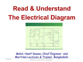
  • 1. Mohd. Hanif Dewan, Chief Engineer and Maritime Lecturer & Trainer, Bangladesh. Read & Understand The Electrical Diagram 7/10/2014 1 Mohd. Hanif Dewan, Chief Engineer and Maritime Lecturer & Trainer, Bangladesh.
  • 2. 10. Read & understand the electrical diagrams Electrical ladder drawings are still one of the common and reliable tools used to troubleshoot equipment when it fails. As with any good troubleshooting tool, one must be familiar with its basic features to make the most of the diagram in the field. In other words, possessing a basic understanding of how the drawing is laid out — as well as the meaning of numbers and symbols found on the schematic — will make you that much more seasoned as a maintenance professional. There are typically two distinct parts of a ladder drawing: I. The power component: The power portion consists of items such as the motor, motor starter contacts and overloads, disconnect(s), and protective devices (fuses and circuit breakers). II. The control component: The control part encompasses items that make the power components do their work. For this discussion, we'll focus on the control portion of the drawing. Let's take a look at the most common components. 7/10/2014 2 Mohd. Hanif Dewan, Chief Engineer and Maritime Lecturer & Trainer, Bangladesh.
  • 3. Fig: A sampling of common symbols you’ll find on the majority of ladder drawings. The normally open and normally closed symbols are added here to merely serve as an instructional aid. Symbols. The symbols that go into making a ladder drawing are the ABCs of print reading (Fig). For instance, in an air compressor system there will be a symbol for a pressure switch. If the person doing the troubleshooting and repair does not recognize that symbol, it will be difficult to locate the switch to determine whether or not it is working properly. 7/10/2014 3 Mohd. Hanif Dewan, Chief Engineer and Maritime Lecturer & Trainer, Bangladesh.
  • 4. Normally Open (NO) and Normally Close (NC): Many times, the input devices are said to be either normally open (NO) or normally closed (NC). The normally open or closed status refers to the shelf state of the device. If a device is normally open, a resistance check of the device with a digital multimeter will give a reading of O.L. If the device is normally closed, a resistance check will give a reading of 0.0. The normally open and normally closed state of the devices is not labeled on the ladder drawing. Rather, you must recognize the symbol. A helpful hint in trying to determine whether the contacts are open or closed is to think of them in terms of gravity. If gravity is acting on the device, its normal state is as shown in the drawing. An exception to this concept is found in devices that contain springs. For instance, in the drawing of a normally open pushbutton, it appears that the pushbutton should be falling down and closing. However, there is a spring in the pushbutton that holds the contacts in the open (up) position. 7/10/2014 4 Mohd. Hanif Dewan, Chief Engineer and Maritime Lecturer & Trainer, Bangladesh.
  • 5. Rails: The drawing is called a ladder drawing because it resembles a ladder in the way it is constructed and presented on the paper. The two vertical lines (wires) that serve as a boundary for the control system and deliver the control voltage to the devices are called the rails. The rails may have overcurrent devices in them (fuses and/or circuit breakers) and may have contacts from control devices. These control lines may be thicker than the others to help better identify them. Like a real ladder, the rails are the supports for the rungs. If the ladder drawing runs across several pages, the control voltage is carried from one page to the next along the rails. There are a number of ways that this may be represented on the drawing. One way this is done is with the use of continuation arrows at the bottom of the first page, which indicates that the rails continue on to another page. The page number on which the rails continue should be noted. On the page where the rails continue, there are also continuation arrows with the page number notation from which the control voltage lines originated. 7/10/2014 5 Mohd. Hanif Dewan, Chief Engineer and Maritime Lecturer & Trainer, Bangladesh.
  • 6. Fig. 2. In this circuit arrangement, the sequence of events could be described as such. When the pushbutton (PB) is pressed down, the circuit is completed and current will flow to energize the coil (CR1). Fig. 2. In this circuit arrangement, the sequence of events could be described as such. When the pushbutton (PB) is pressed down, the circuit is completed and current will flow to energize the coil (CR1). Rungs: The rungs of the ladder are made up of wires and input devices that either allow current flow or interrupt current flow to the output devices. These lines may be thin lines when compared to the lines of the rails. From the placement of the input and output devices, you can determine the sequence of events that either energize or de-energize the outputs. The key to good troubleshooting is determining this sequence of events. Input devices are typically placed on the left side of the rungs, while the output devices are placed on the right (Fig. 2).7/10/2014 6 Mohd. Hanif Dewan, Chief Engineer and Maritime Lecturer & Trainer, Bangladesh.
  • 7. Placement of input devices: The input devices are placed on the rungs in a way that indicates the current flow through the rung when there is a complete path to the outputs. There are several ways in which these input devices can be placed on the rungs, although as stated earlier, they are typically placed on the left side. The STOP input devices are typically normally closed and are placed in series on the rung. This means that they are placed end to end in the drawing. In order for the current to flow through them, they must be in the closed position. Typical STOP input devices include components such as normally closed pushbuttons and mushroom head buttons, limit switches, and contacts for light curtains, photocells, and proximity switches. 7/10/2014 7 Mohd. Hanif Dewan, Chief Engineer and Maritime Lecturer & Trainer, Bangladesh.
  • 8. The START input devices are typically normally open and are usually placed in series with and after the STOP devices. If there is more than one START device, it is usually placed in parallel with the others. When the STOP and START devices are placed in order on the rung, the flow of current to the output devices can be seen. Understanding this flow is a great aide in troubleshooting. A key question to always ask yourself is: “What does it take to energize the output?” Fig. 3. This circuit arrangement uses all three types of logic functions: AND, OR, and AND/OR. Fig. 3. This circuit arrangement uses all three types of logic functions: AND, OR, and AND/OR. 7/10/2014 8 Mohd. Hanif Dewan, Chief Engineer and Maritime Lecturer & Trainer, Bangladesh.
  • 9. Here's a simple example to analyze. In Fig. 3, what does it take to energize the output CR1? When either start pushbutton is depressed, the path is complete, and the coil of CR1 is energized. In following the path for the current, you can see the logic of the placement of the input devices. This logic determines the decision making process of the input devices and the path for current as it travels to energize the outputs. Logic statements: There are several logic statements that can be used in placing the input devices in the rungs. The most common of these are the AND, the OR, and the combination AND/OR function. In Fig. 3, all three are present. 1. The end-to-end placement of the stop and start pushbuttons makes an AND logic statement. In other words, both the stop AND the start buttons must be used to energize the coil.7/10/2014 9 Mohd. Hanif Dewan, Chief Engineer and Maritime Lecturer & Trainer, Bangladesh.
  • 10. 2. The parallel placements of the start buttons makes an OR logic statement. Either start pushbutton will complete the path and energize the coil. 3. Placing the stop pushbutton in series with the parallel start pushbuttons supports the AND/OR logic statement. Placement of the output devices. As noted earlier, the output devices are placed on the right side of the ladder drawing. Unlike input devices, it's important that the output devices only be placed in parallel. If they are placed in series, electrical theory says that the voltage will drop across the resistance of each output. If this happens, they will not operate properly. Outputs include items such as lights, coils, solenoids, and heating elements. In addition to the commonly accepted symbols shown in Fig. 1, letters and numbers also help to identify the output devices. 7/10/2014 10 Mohd. Hanif Dewan, Chief Engineer and Maritime Lecturer & Trainer, Bangladesh.
  • 11. Fig. 4. As noted by the numbers on the right rail, this circuit arrangement indicates there is a normally open contact in Rung 2 and a normally closed contact in Rung 3. Fig. 4. As noted by the numbers on the right rail, this circuit arrangement indicates there is a normally open contact in Rung 2 and a normally closed contact in Rung 3. Coils will typically have contacts associated with them. These contacts will change state when the coil is energized. The changing contacts will either complete or open the path for current. As noted in Fig. 4, when the pushbutton is pressed down, the path is completed, and current will flow to energize the coil. When the coil is energized, the contacts associated with the coil will change state. The red light will go on, and the green light will go off. 7/10/2014 11 Mohd. Hanif Dewan, Chief Engineer and Maritime Lecturer & Trainer, Bangladesh.
  • 12. Locating the contacts: In the ladder drawing, the contacts associated with the coil can be located using a cross-reference system. The rungs are usually numbered on the left side of the rail. A number on the right side of the rail references the contacts associated with the coil (Fig. 4). These numbers are the rungs in which the contacts can be found. A number without a line under it references an open contact. Drawing a line under the number on the right rail references a closed contact. Let us see a teaching video for “Reading Electrical Diagram” 7/10/2014 12 Mohd. Hanif Dewan, Chief Engineer and Maritime Lecturer & Trainer, Bangladesh.
  • 13. “How to read an Electrical Diagram” 7/10/2014 Mohd. Hanif Dewan, Chief Engineer and Maritime Lecturer & Trainer, Bangladesh. 13
  • 14. Reference: 1. www.realfixerrealfast.com 7/10/2014 14 Mohd. Hanif Dewan, Chief Engineer and Maritime Lecturer & Trainer, Bangladesh.
  • 15. 7/10/2014 15 Mohd. Hanif Dewan, Chief Engineer and Maritime Lecturer & Trainer, Bangladesh.
  • 16. 7/10/2014 16 Mohd. Hanif Dewan, Chief Engineer and Maritime Lecturer & Trainer, Bangladesh.
  • 17. Wires and connections Component Circuit Symbol Function of Component Wire To pass current very easily from one part of a circuit to another. Wires joined A 'blob' should be drawn where wires are connected (joined), but it is sometimes omitted. Wires connected at 'crossroads' should be staggered slightly to form two T-junctions, as shown on the right. Wires not joined In complex diagrams it is often necessary to draw wires crossing even though they are not connected. The simple crossing on the left is correct but may be misread as a join where the 'blob' has been forgotten. The bridge symbol on the right leaves no doubt! Power Supplies Component Circuit Symbol Function of Component Cell Supplies electrical energy. The larger terminal (on the left) is positive (+). A single cell is often called a battery, but strictly a battery is two or more cells joined together. Battery Supplies electrical energy. A battery is more than one cell. The larger terminal (on the left) is positive (+). 7/10/2014 17 Mohd. Hanif Dewan, Chief Engineer and Maritime Lecturer & Trainer, Bangladesh.
  • 18. 7/10/2014 18 Mohd. Hanif Dewan, Chief Engineer and Maritime Lecturer & Trainer, Bangladesh.
  • 19. 7/10/2014 19 Mohd. Hanif Dewan, Chief Engineer and Maritime Lecturer & Trainer, Bangladesh.
  • 20. 7/10/2014 20 Mohd. Hanif Dewan, Chief Engineer and Maritime Lecturer & Trainer, Bangladesh.
  • 21. 7/10/2014 21 Mohd. Hanif Dewan, Chief Engineer and Maritime Lecturer & Trainer, Bangladesh.
  • 22. 7/10/2014 22 Mohd. Hanif Dewan, Chief Engineer and Maritime Lecturer & Trainer, Bangladesh.
  • 23. 7/10/2014 23 Mohd. Hanif Dewan, Chief Engineer and Maritime Lecturer & Trainer, Bangladesh.
  • 24. 7/10/2014 24 Mohd. Hanif Dewan, Chief Engineer and Maritime Lecturer & Trainer, Bangladesh.
  • 25. 7/10/2014 25 Mohd. Hanif Dewan, Chief Engineer and Maritime Lecturer & Trainer, Bangladesh.
  • 26. 7/10/2014 26 Mohd. Hanif Dewan, Chief Engineer and Maritime Lecturer & Trainer, Bangladesh.
  • 27. 7/10/2014 27 Mohd. Hanif Dewan, Chief Engineer and Maritime Lecturer & Trainer, Bangladesh.
  • 28. 7/10/2014 28 Mohd. Hanif Dewan, Chief Engineer and Maritime Lecturer & Trainer, Bangladesh.
  • 29. 7/10/2014 29 Mohd. Hanif Dewan, Chief Engineer and Maritime Lecturer & Trainer, Bangladesh.
  • 30. 7/10/2014 30 Mohd. Hanif Dewan, Chief Engineer and Maritime Lecturer & Trainer, Bangladesh.
  • 31. 7/10/2014 31 Mohd. Hanif Dewan, Chief Engineer and Maritime Lecturer & Trainer, Bangladesh.
  • 32. LET’S READ A DIAGRAM 7/10/2014 32 Mohd. Hanif Dewan, Chief Engineer and Maritime Lecturer & Trainer, Bangladesh.
  • 33. 7/10/2014 33 Mohd. Hanif Dewan, Chief Engineer and Maritime Lecturer & Trainer, Bangladesh.
  • 34. 7/10/2014 34 Mohd. Hanif Dewan, Chief Engineer and Maritime Lecturer & Trainer, Bangladesh.
  • 35. 7/10/2014 35 Mohd. Hanif Dewan, Chief Engineer and Maritime Lecturer & Trainer, Bangladesh.
  • 36. 7/10/2014 36 Mohd. Hanif Dewan, Chief Engineer and Maritime Lecturer & Trainer, Bangladesh.
  • 37. 7/10/2014 37 Mohd. Hanif Dewan, Chief Engineer and Maritime Lecturer & Trainer, Bangladesh.
  • 38. 7/10/2014 38 Mohd. Hanif Dewan, Chief Engineer and Maritime Lecturer & Trainer, Bangladesh.
  • 39. 7/10/2014 39 Mohd. Hanif Dewan, Chief Engineer and Maritime Lecturer & Trainer, Bangladesh.
  • 40. 7/10/2014 40 Mohd. Hanif Dewan, Chief Engineer and Maritime Lecturer & Trainer, Bangladesh.
  • 41. 7/10/2014 41 Mohd. Hanif Dewan, Chief Engineer and Maritime Lecturer & Trainer, Bangladesh.
  • 42. 7/10/2014 42 Mohd. Hanif Dewan, Chief Engineer and Maritime Lecturer & Trainer, Bangladesh.
  • 43. 7/10/2014 43 Mohd. Hanif Dewan, Chief Engineer and Maritime Lecturer & Trainer, Bangladesh.
  • 44. 7/10/2014 44 Mohd. Hanif Dewan, Chief Engineer and Maritime Lecturer & Trainer, Bangladesh.
  • 45. 7/10/2014 45 Mohd. Hanif Dewan, Chief Engineer and Maritime Lecturer & Trainer, Bangladesh.
  • 46. 7/10/2014 46 Mohd. Hanif Dewan, Chief Engineer and Maritime Lecturer & Trainer, Bangladesh.
  • 47. ANY QUESTION? THANK YOU! 7/10/2014 Mohd. Hanif Dewan, Chief Engineer and Maritime Lecturer & Trainer, Bangladesh. 47