Downloaded 601 times

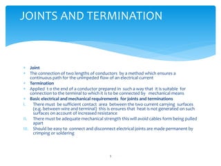
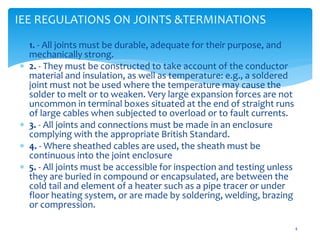


The document outlines various methods and requirements for making joints and terminations in electrical conductors, including detailed information on the types of terminals and joints, such as soldering, welding, and crimping. It emphasizes the importance of mechanical strength, durability, and adherence to IEE regulations for safety and effectiveness in electrical installations. Additionally, the document describes different soldering techniques and the materials used in these processes.


