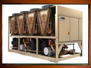
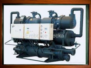
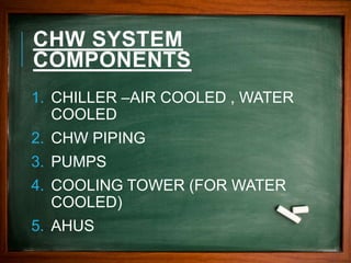
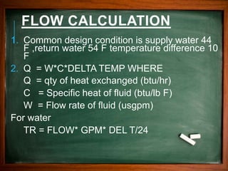
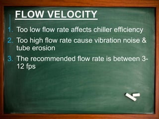
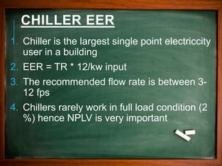
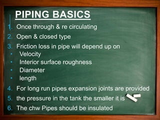
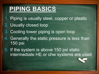
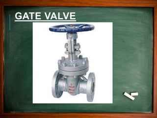
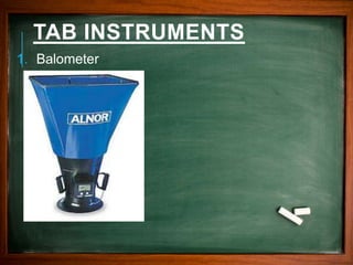
NASEEM AP
WWW.GILLSENERGY.COM
CHILLED WATER
SYSTEM
CHW SYSTEM
COMPONENTS
1. CHILLER –AIR COOLED , WATER
COOLED
2. CHW PIPING
3. PUMPS
4. COOLING TOWER (FOR WATER
COOLED)
5. AHUS
CHILLER BASICS
1. Chilled water flows thru the evaporator .The
evaporator is a heat exchanger
2. Chiller compressor may be centrifugal,
scroll, screw or reciprocating
3. The condenser may air cooled or water
cooled
4. There can be multiple chillers in a chw
plant
FLOW CALCULATION
1. Common design condition is supply water 44
F ,return water 54 F temperature difference 10
F
2. Q = W*C*DELTA TEMP WHERE
Q = qty of heat exchanged (btu/hr)
C = Specific heat of fluid (btu/lb F)
W = Flow rate of fluid (usgpm)
For water
TR = FLOW* GPM* DEL T/24
FLOW VELOCITY
1. Too low flow rate affects chiller efficiency
2. Too high flow rate cause vibration noise &
tube erosion
3. The recommended flow rate is between 3-
12 fps
CHILLER EER
1. Chiller is the largest single point electriccity
user in a building
2. EER = TR * 12/kw input
3. The recommended flow rate is between 3-
12 fps
4. Chillers rarely work in full load condition (2
%) hence NPLV is very important
EXPANSION TANK
1. Essential to manage the thermal expansion
2. Can be open type or closed type
3. Open tanks must be located above the
highest point
4. Air water interface or diaphragm tank can
be located anywhere in the system
5. The lower the pressure in the tank the
smaller it is
PIPING BASICS
1. Once through & re circulating
2. Open & closed type
3. Friction loss in pipe will depend up on
 Velocity
 Interior surface roughness
 Diameter
 length
4. For long run pipes expansion joints are provided
5. the pressure in the tank the smaller it is
6. The chw Pipes should be insulated
PIPING BASICS
1. Piping is usually steel, copper or plastic
2. Usually closed loop
3. Cooling tower piping is open loop
4. Generally the static pressure is less than
150 psi
5. If the system is above 150 psi static
intermediate HE or chw systems are used
PIPING VALVES
1. 2 way or 3 way valve to direct/by pass the
flow
2. Balancing valve to control the flow
3. Gate valves for isolation
4. Globe valves for throttling
5. Butterfly valves – Isolation, throttling
6. Strainers- For filtration
7. Flexible bellows –Vibration arresting
8. NRV-at pump discharge
9. Pressure & temperature gauges
BALANCING VALVE
TRIPLE DUTY VALVE
GATE VALVE
BUTTERFLY VALVE
STRAINER VALVE
FLEXIBLE BELLOW
2 WAY & 3 WAY VALVE
BALL VALVE
TAB BASICS
1. HVAC Piping testing procedure
 Pressure testing
 Evacuation
 Gas charging
2. Water pipe ling is balance with balancing
valves
3. Air side balancing done by vcd s & dampers
TAB INSTRUMENTS
1. Vacuum pump
TAB INSTRUMENTS
1. Manifold gauges
TAB INSTRUMENTS
1. Manometer
TAB INSTRUMENTS
1. Balometer

Chilled water piping basics

  • 1.
  • 5.
    CHW SYSTEM COMPONENTS 1. CHILLER–AIR COOLED , WATER COOLED 2. CHW PIPING 3. PUMPS 4. COOLING TOWER (FOR WATER COOLED) 5. AHUS
  • 6.
    CHILLER BASICS 1. Chilledwater flows thru the evaporator .The evaporator is a heat exchanger 2. Chiller compressor may be centrifugal, scroll, screw or reciprocating 3. The condenser may air cooled or water cooled 4. There can be multiple chillers in a chw plant
  • 7.
    FLOW CALCULATION 1. Commondesign condition is supply water 44 F ,return water 54 F temperature difference 10 F 2. Q = W*C*DELTA TEMP WHERE Q = qty of heat exchanged (btu/hr) C = Specific heat of fluid (btu/lb F) W = Flow rate of fluid (usgpm) For water TR = FLOW* GPM* DEL T/24
  • 8.
    FLOW VELOCITY 1. Toolow flow rate affects chiller efficiency 2. Too high flow rate cause vibration noise & tube erosion 3. The recommended flow rate is between 3- 12 fps
  • 9.
    CHILLER EER 1. Chilleris the largest single point electriccity user in a building 2. EER = TR * 12/kw input 3. The recommended flow rate is between 3- 12 fps 4. Chillers rarely work in full load condition (2 %) hence NPLV is very important
  • 10.
    EXPANSION TANK 1. Essentialto manage the thermal expansion 2. Can be open type or closed type 3. Open tanks must be located above the highest point 4. Air water interface or diaphragm tank can be located anywhere in the system 5. The lower the pressure in the tank the smaller it is
  • 11.
    PIPING BASICS 1. Oncethrough & re circulating 2. Open & closed type 3. Friction loss in pipe will depend up on  Velocity  Interior surface roughness  Diameter  length 4. For long run pipes expansion joints are provided 5. the pressure in the tank the smaller it is 6. The chw Pipes should be insulated
  • 13.
    PIPING BASICS 1. Pipingis usually steel, copper or plastic 2. Usually closed loop 3. Cooling tower piping is open loop 4. Generally the static pressure is less than 150 psi 5. If the system is above 150 psi static intermediate HE or chw systems are used
  • 14.
    PIPING VALVES 1. 2way or 3 way valve to direct/by pass the flow 2. Balancing valve to control the flow 3. Gate valves for isolation 4. Globe valves for throttling 5. Butterfly valves – Isolation, throttling 6. Strainers- For filtration 7. Flexible bellows –Vibration arresting 8. NRV-at pump discharge 9. Pressure & temperature gauges
  • 16.
  • 17.
  • 18.
  • 19.
  • 20.
  • 21.
  • 22.
    2 WAY &3 WAY VALVE
  • 23.
  • 24.
    TAB BASICS 1. HVACPiping testing procedure  Pressure testing  Evacuation  Gas charging 2. Water pipe ling is balance with balancing valves 3. Air side balancing done by vcd s & dampers
  • 25.
  • 26.
  • 27.
  • 28.