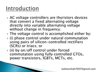
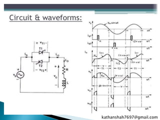
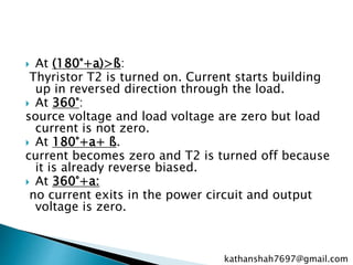
2. AC voltage controllers are thyristors devices
that convert a fixed alternating voltage
directly into variable alternating voltage
without change in frequency.
The voltage control is accomplished either by:
(i) phase control under natural commutation
using pairs of silicon-controlled rectifiers
(SCRs) or triacs; or
(ii) by on/off control under forced
commutation using fully controlled GTOs,
power transistors, IGBTs, MCTs, etc.
kathanshah7697@gmail.com
4. During 0 to 180°: T1 is forward biased.
At a: T1 is triggered and current starts building up through the
load.
• At 180°
load and source voltages are zero but current is not zero because
of the presence of inductance in the load circuit.
• At ß>180°:
load current reduces to zero.
After 180°:
T1 is reverse biased but doesnot turn off because load current
is not zero.
• At ß:
load current is zero, T1 is turned off as it is already reverse
biased.
• From ß to 180°+a
no current exits in the power circuit so output voltage
is zero
kathanshah7697@gmail.com
5. At (180°+a)>ß:
Thyristor T2 is turned on. Current starts building
up in reversed direction through the load.
At 360°:
source voltage and load voltage are zero but load
current is not zero.
At 180°+a+ ß.
current becomes zero and T2 is turned off because
it is already reverse biased.
At 360°+a:
no current exits in the power circuit and output
voltage is zero.
kathanshah7697@gmail.com
6. Voltage across thyristors appear only when
both of them are in off state. In this state,
positive voltage appears across thyristor if
it is forward biased and not conducting,
negative voltage appears across thyristor if
it is reverse biased and not conducting. If
any one thyristor is on, voltage drop across
both (on and off) thyristors is zero because
of there parallel connection ( voltage drop
across devices connected in parallel is
same).
kathanshah7697@gmail.com