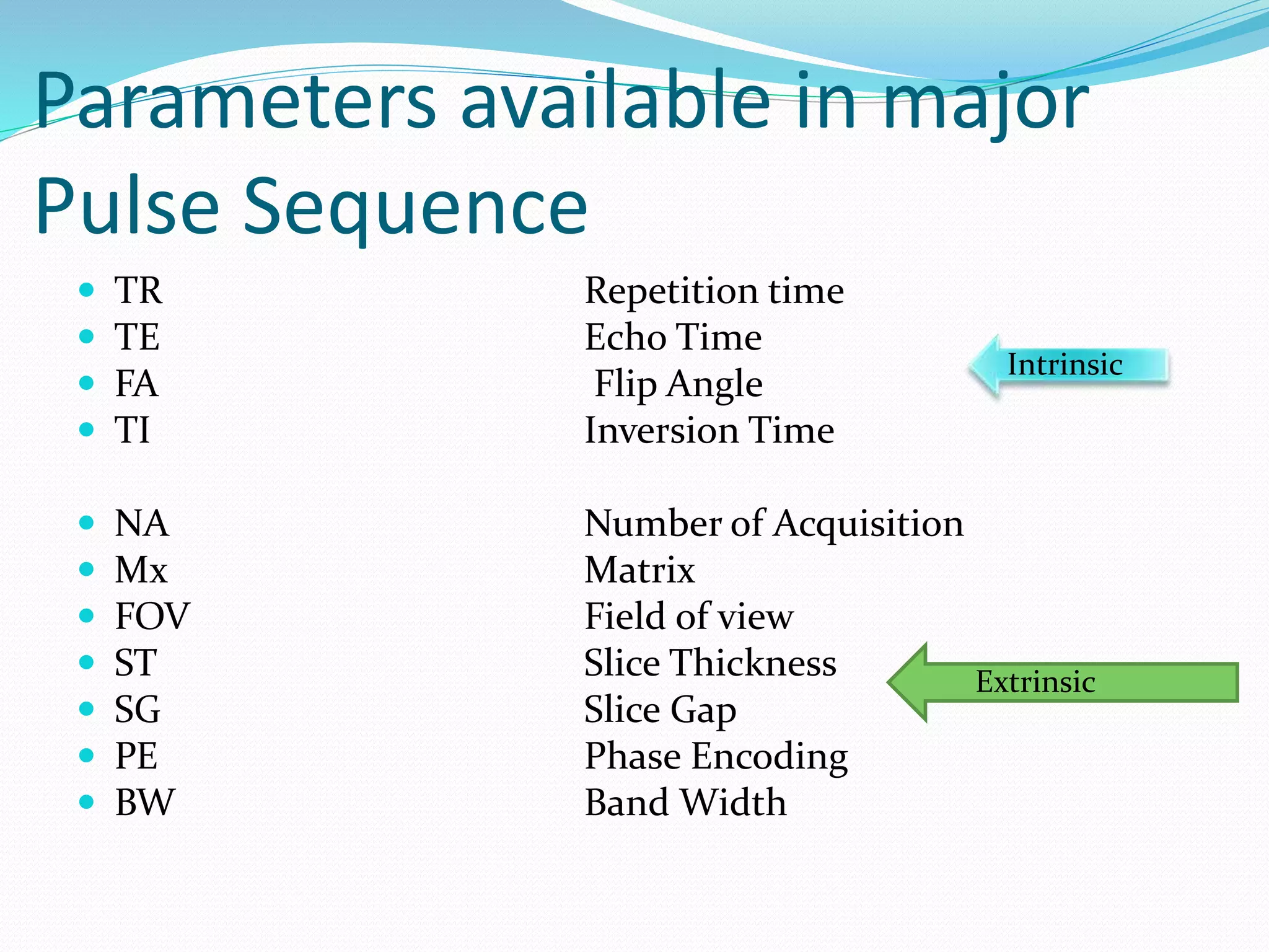
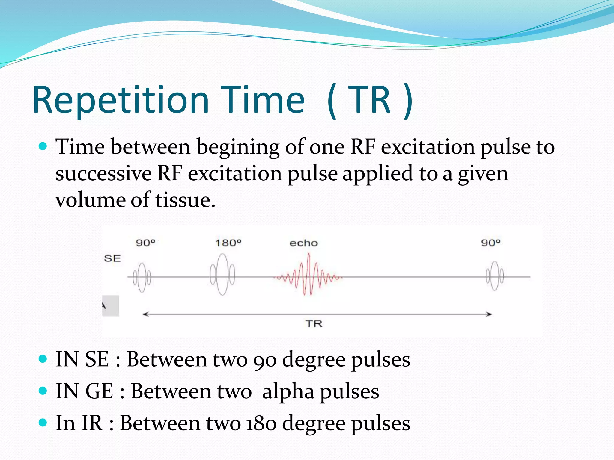
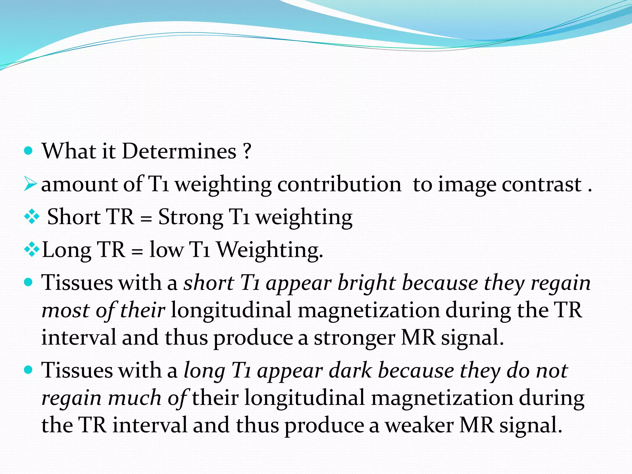
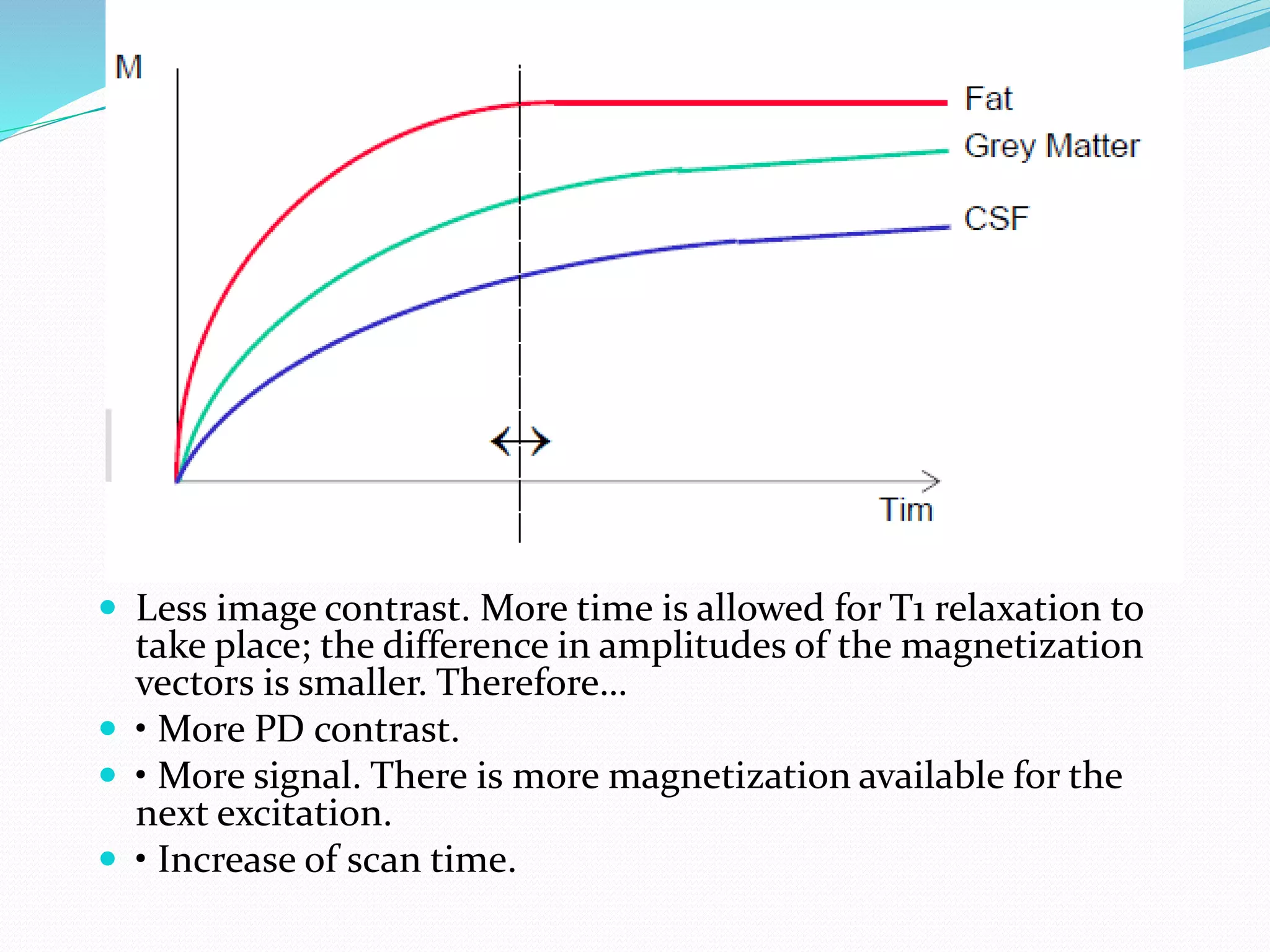
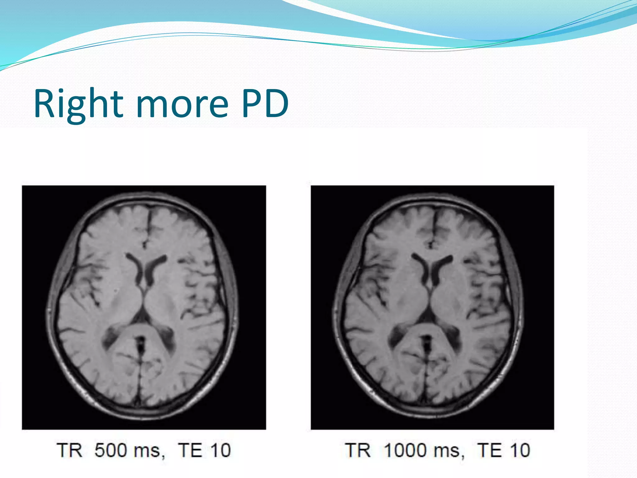
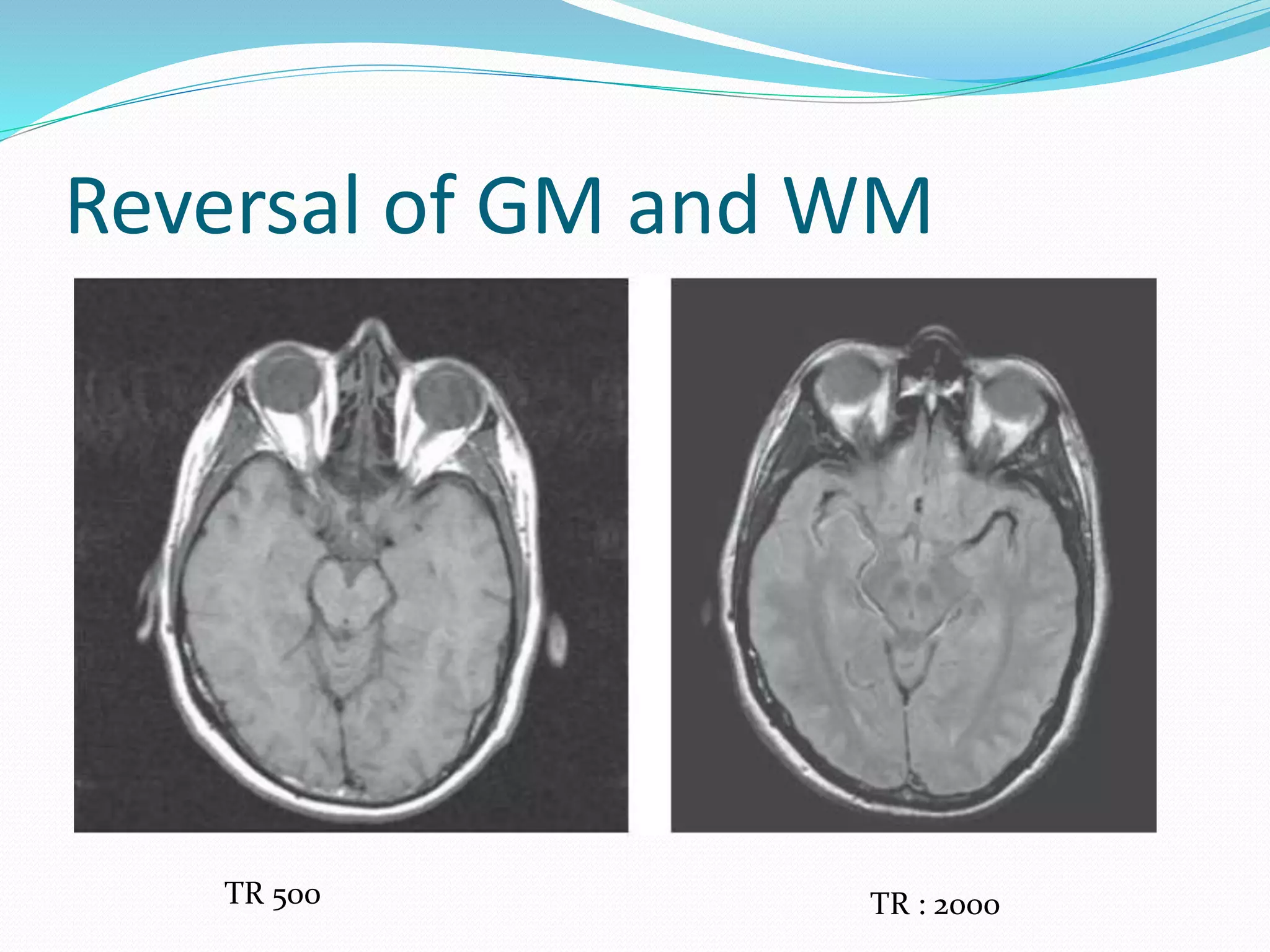
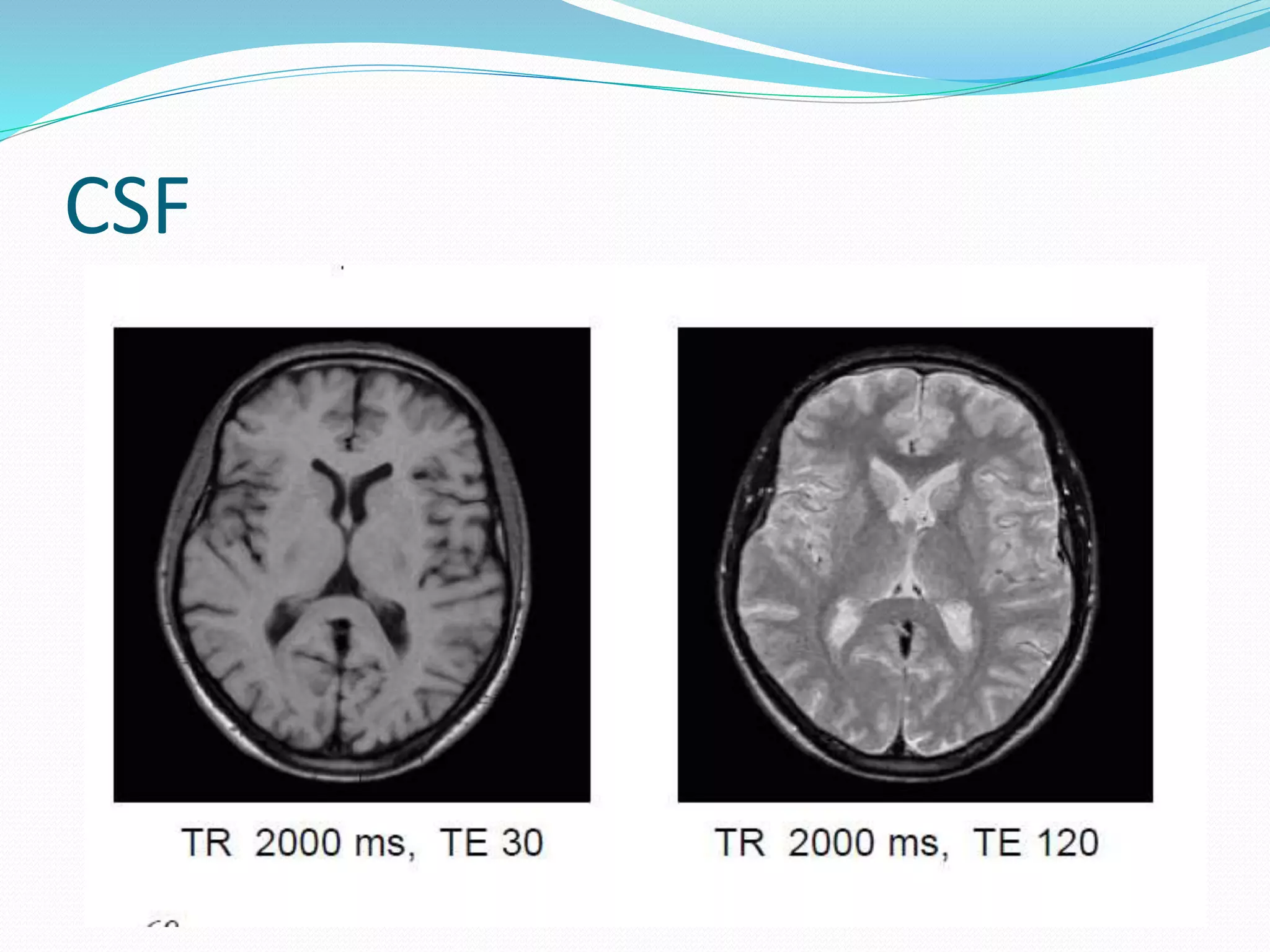
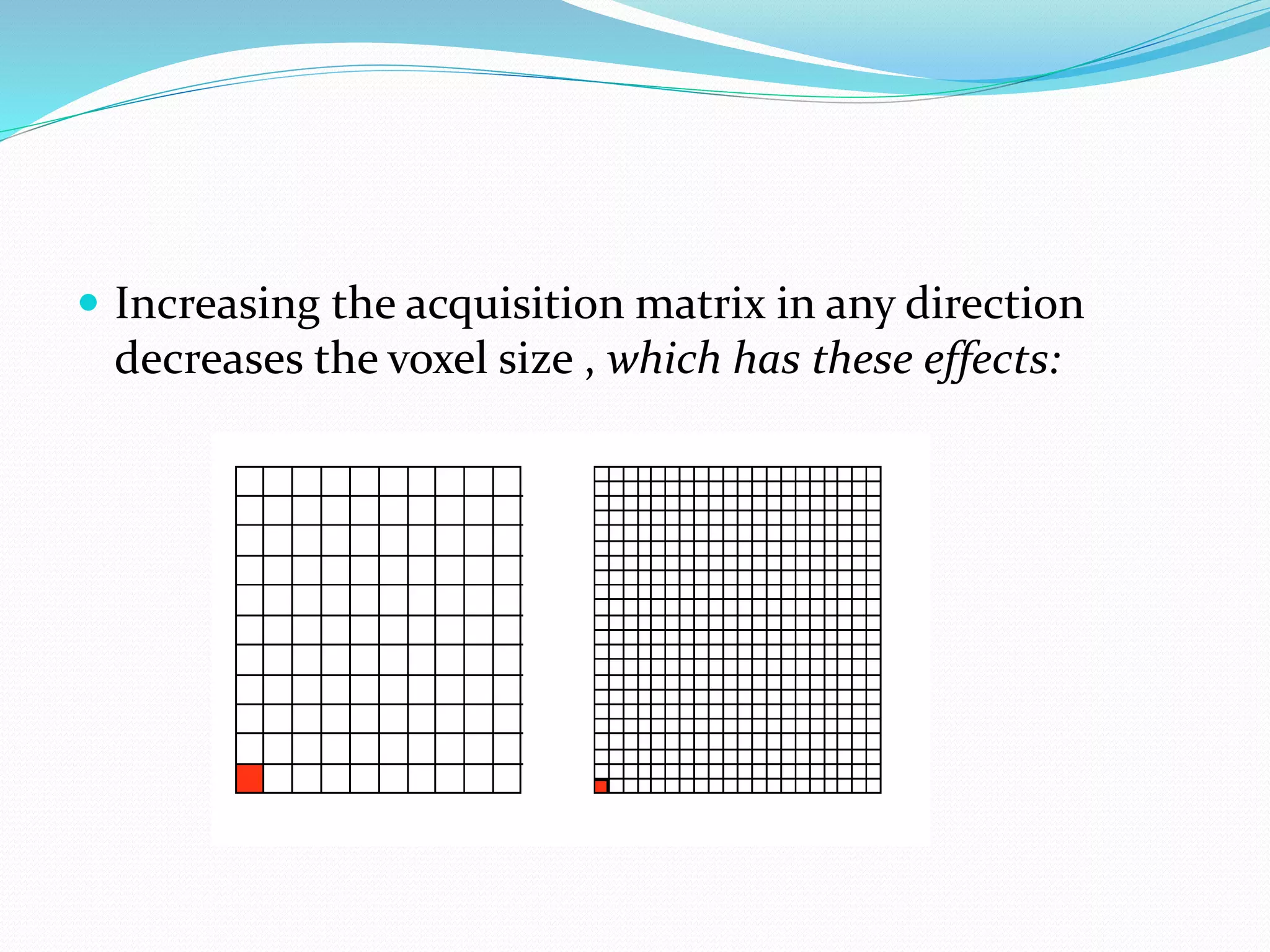
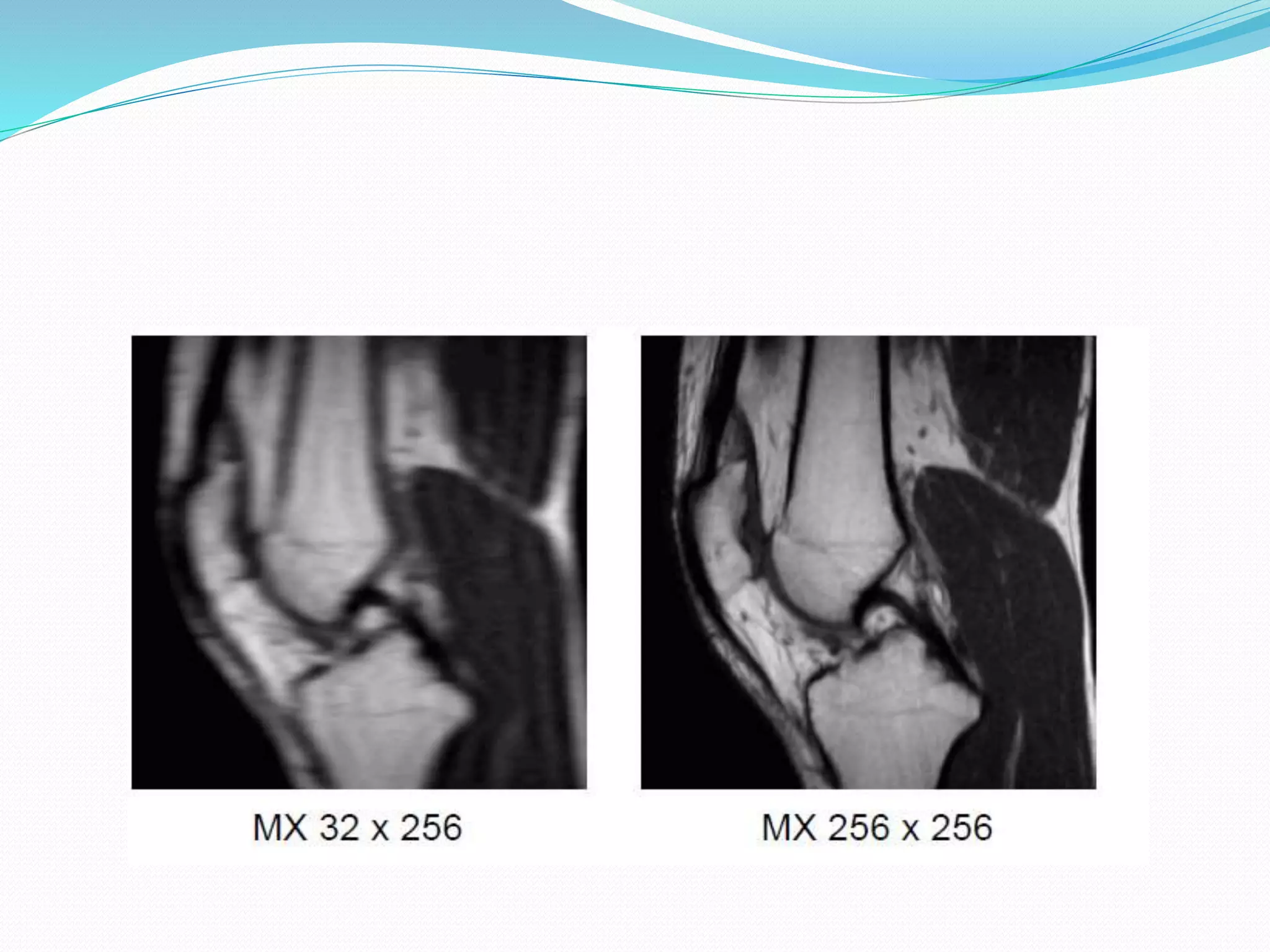
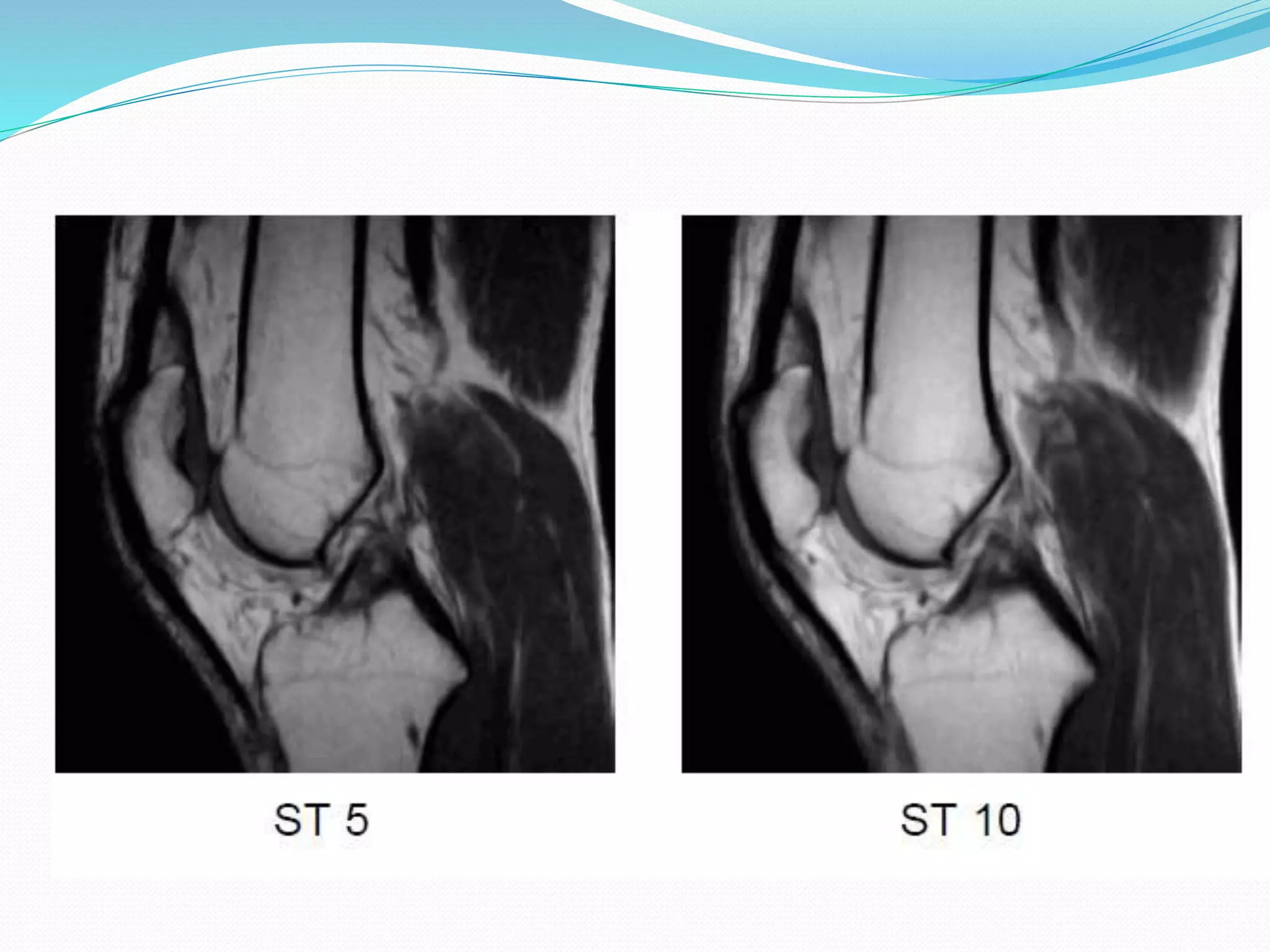
3. Parameters available in major
Pulse Sequence
TR Repetition time
TE Echo Time
FA Flip Angle
TI Inversion Time
NA Number of Acquisition
Mx Matrix
FOV Field of view
ST Slice Thickness
SG Slice Gap
PE Phase Encoding
BW Band Width
Intrinsic
Extrinsic
4. Basis of their Effect on Image
Intrinsic Parameter
Modify the Inherent Signal Produced by Volume
Element
Only Signal Producing portion of Image which is
Patient Anatomy.
External Parameter
Influence the Mechanics of data Collection ( e.g: Voxel
size) or others factors external to tissue
5. Repetition Time ( TR )
Time between begining of one RF excitation pulse to
successive RF excitation pulse applied to a given
volume of tissue.
IN SE : Between two 90 degree pulses
IN GE : Between two alpha pulses
In IR : Between two 180 degree pulses
6. What it Determines ?
amount of T1 weighting contribution to image contrast .
Short TR = Strong T1 weighting
Long TR = low T1 Weighting.
Tissues with a short T1 appear bright because they regain
most of their longitudinal magnetization during the TR
interval and thus produce a stronger MR signal.
Tissues with a long T1 appear dark because they do not
regain much of their longitudinal magnetization during
the TR interval and thus produce a weaker MR signal.
7. Less image contrast. More time is allowed for T1 relaxation to
take place; the difference in amplitudes of the magnetization
vectors is smaller. Therefore…
• More PD contrast.
• More signal. There is more magnetization available for the
next excitation.
• Increase of scan time.
10. ECHO TIME ( TE )
Time between the excitation pulse and middle of
Echo . ( signal Maximum ).
11. determines the influence of T2 on image contrast.
Short TE → low T2 weighting
Long TE → strong T2 weighting
Tissues with a short T2 appear dark on T2-weighted images,
tissues with a long T2 appear bright on T2-weighted images!
tissues with a short T2 having lost most of their signal
appear dark on the image while
tissues with a long T2 still produce a stronger signal and
thus appear bright.
12. More T2 contrast. An increase of TE allows for more dephasing.
• Less signal.
• Possible contrast swap. Notice that the relaxation curve of CSF
in cross the one from gray matter. This means that with an early
echo gray matter is brighter than CSF, while a late echo shows the
opposite.
15. FLIP ANGLE
The Flip Angle determines how much the net
magnetization vector is rotated towards the X-Y plane
In SE and IR sequences FA is most of the times 90º.
In GE sequences, however, FA can have values in the
range of 1º ~ 90º
controls the
amount of transverse magneti zation
that is created which induces
a signal in the coil
16. Increasing FA has :
More T1 contrast.
• More signal.
• Possible contrast swap.
17. INVERSION TIME ( IR )
The Inversion Time is the time between an 180º
excitation pulse and the 90º-excitation pulse
only used in IR type sequences and in a special kind of
GE sequences (TurboGE)
20. Number of Acquisition
is the number of times the signal from a given slice for
a given phase encoding amplitude is measured and
added together.
Performed in order to increase the SNR ratio.
The extra signal that is acquired is then averaged
resulting in a better SNR and therefore in a better
image
selecting NA=2 doubles the scan time, but the SNR is
only increased by √2, which is 1.4 times!! In order to
double the SNR, you’ll have to select NA=4
21. Increasing NA has:
More signal (√NA).
• “Less” noise.
• Fewer artifacts due to signal averaging. The higher
NA, the better the image.
• Increase of scan time.
23. Matrix ( MX )
The (acquisition) Matrix determines the spatial resolution
of our image.
It consists of two sides: one specifies
the number of phase encoding steps MXPE (NPE) and the
other specifies the number
of readout sampling data points MXRO(NRO).
The display matrix can have two sizes 256 or 512..
acquisition matrix can have just about any size from 32 ~
1024 with increments of 32 .
When an acquisition matrix of 192x256 is scanned, it will
be reconstructed and displayed in 256x256 display matrix
24. Increasing the acquisition matrix in any direction
decreases the voxel size , which has these effects:
25. Lower signal. A smaller voxel contains fewer protons,
which can contribute to the signal/voxel.
• Higher spatial resolution.
• Increase of scan time. This only happens when MXPE
is increased (more lines are to be filled in k-space =
more time). Increasing MXRO has no effect on scan
time.
26.
27. Field of View (FOV)
determines how much of the patient we are going to
see.
Increasing the FOV size also increases the voxel size
28. Increasing FOV has Effect:
Increased signal. Increasing the voxel size also
increases the number of protons, which can contribute
to the signal/voxel. (SNR is increased by x2).
• Lower spatial resolution.
• Increased viewing area.
29.
30. Slice Thickness ( ST )
The Slice Thickness influences the amount of signal,
as well as the sharpness of an image. By changing ST
from 10 mm to 5 mm we lose 50% signal
31. Increased signal. The voxel size increases, so more
protons can contribute to the SNR.
• Lower resolution. This is straightforward.
• Increased “partial volume” effect. Partial volume
effect occurs when an object, such as an adrenal gland
is cut in half by a slice. If the signal would be high it
would show on the image, but the size might be
misinterpreted. Keep ST as thin as possible.
• Larger object coverage.