Buck converter.pdf
•
0 likes•226 views

SIMULATION MODEL OF BUCK CONVERTER

Recommended
More Related Content
What's hot
What's hot (20)
Similar to Buck converter.pdf
Similar to Buck converter.pdf (20)
More from Indian Institute of Technology Guwahati
More from Indian Institute of Technology Guwahati (13)
Recently uploaded
Recently uploaded (20)
Buck converter.pdf
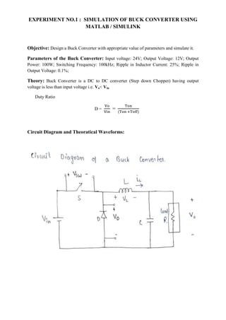
- 1. EXPERIMENT NO.1 : SIMULATION OF BUCK CONVERTER USING MATLAB / SIMULINK Objective: Design a Buck Converter with appropriate value of parameters and simulate it. Parameters of the Buck Converter: Input voltage: 24V; Output Voltage: 12V; Output Power: 100W; Switching Frequency: 100kHz; Ripple in Inductor Current: 25%; Ripple in Output Voltage: 0.1%; Theory: Buck Converter is a DC to DC converter (Step down Chopper) having output voltage is less than input voltage i.e. Vo< Vin Duty Ratio D = = Circuit Diagram and Theoratical Waveforms:
- 2. Design procedure and final design parameters obtained: 1. Duty Ratio: D = So, D=0.5 2. Ripple in Inductor Current: ΔIL (Theoretical) = 2.08Amp. ΔIL = So, L = 28.85µH where f is switching frequency
- 3. 3. Ripple in Output Voltage: ΔVo (Theoretical) = 0.012V ΔVo = So, C = 217µF 4. Avg Current through Inductor (Theoretical): IDC = IDC = 8.33Amp. 5. Load Resistance: RL (Fixed) = = 1.44Ω Results: 1. Simulation Model of Buck Converter: Here we are taking 100 Samples for each Time period So, Sampling frequency is 100 times of switching frequency(100kHz). So, Sampling Time Period = 100nSec.
- 4. 2. Source Voltage Waveform: Vin = 24V Time (sec.) 3. Switching signal to turn ON/OFF to MOSFET: 4. Voltage Across the Diode: When Diode is OFF VD = 24 V When Diode is ON VD = -0.8V
- 5. 5. Voltage across the Switch/MOSFET: When MOSFET/switch is ON VSW = 0.8V When MOSFET/switch is OFF VSW = 24V
- 6. 6. Current through Inductor: Avg Current through Inductor (Practical) IDC = 7.9Amp. Ripple in Inductor Current (Practical) ΔIL = 2Amp. 7. Output voltage: Output Avg. Voltage (Practical) Vo=11.43V Ripple in Output Voltage (Practical) ΔVo = 0.011V