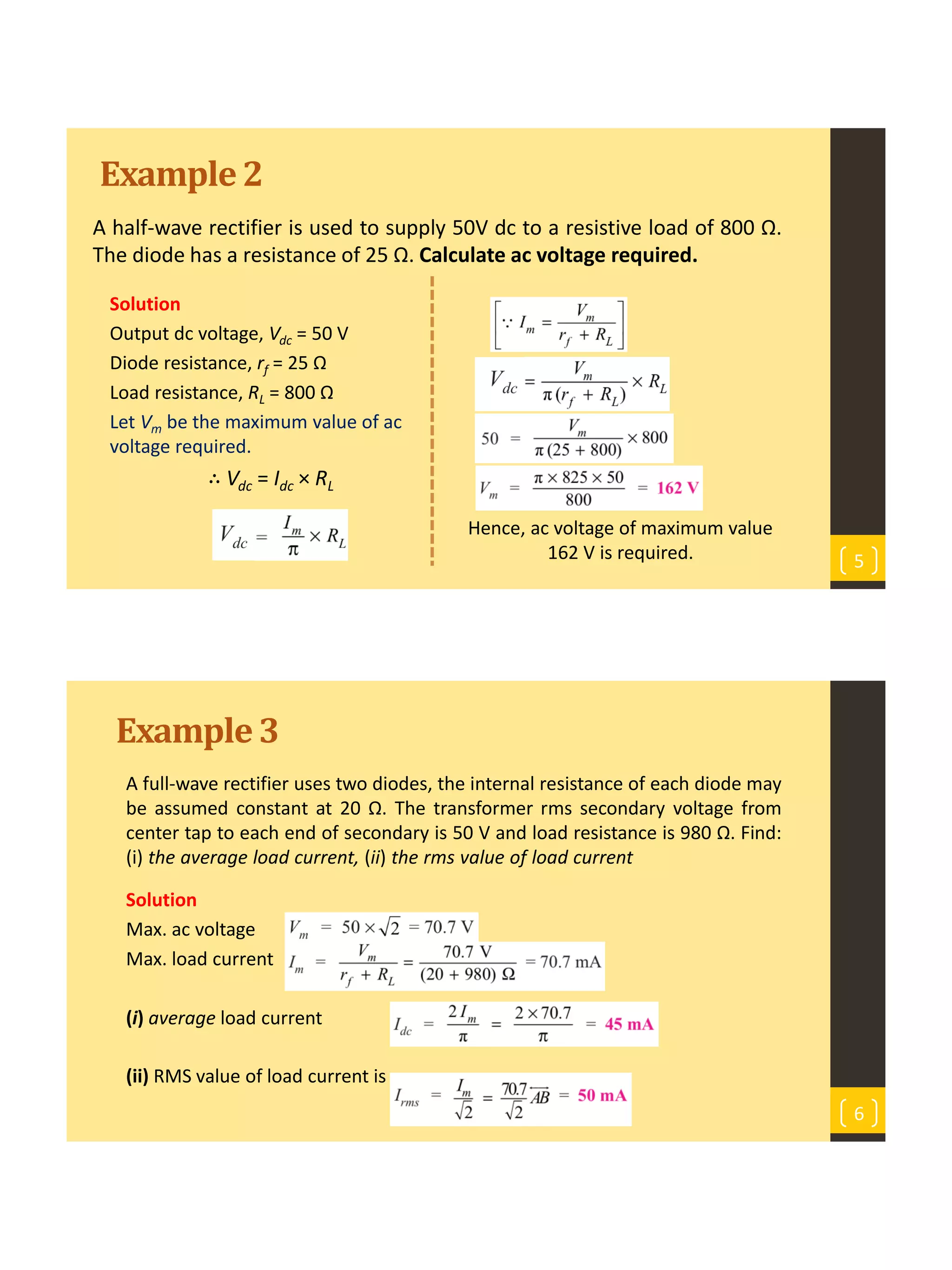
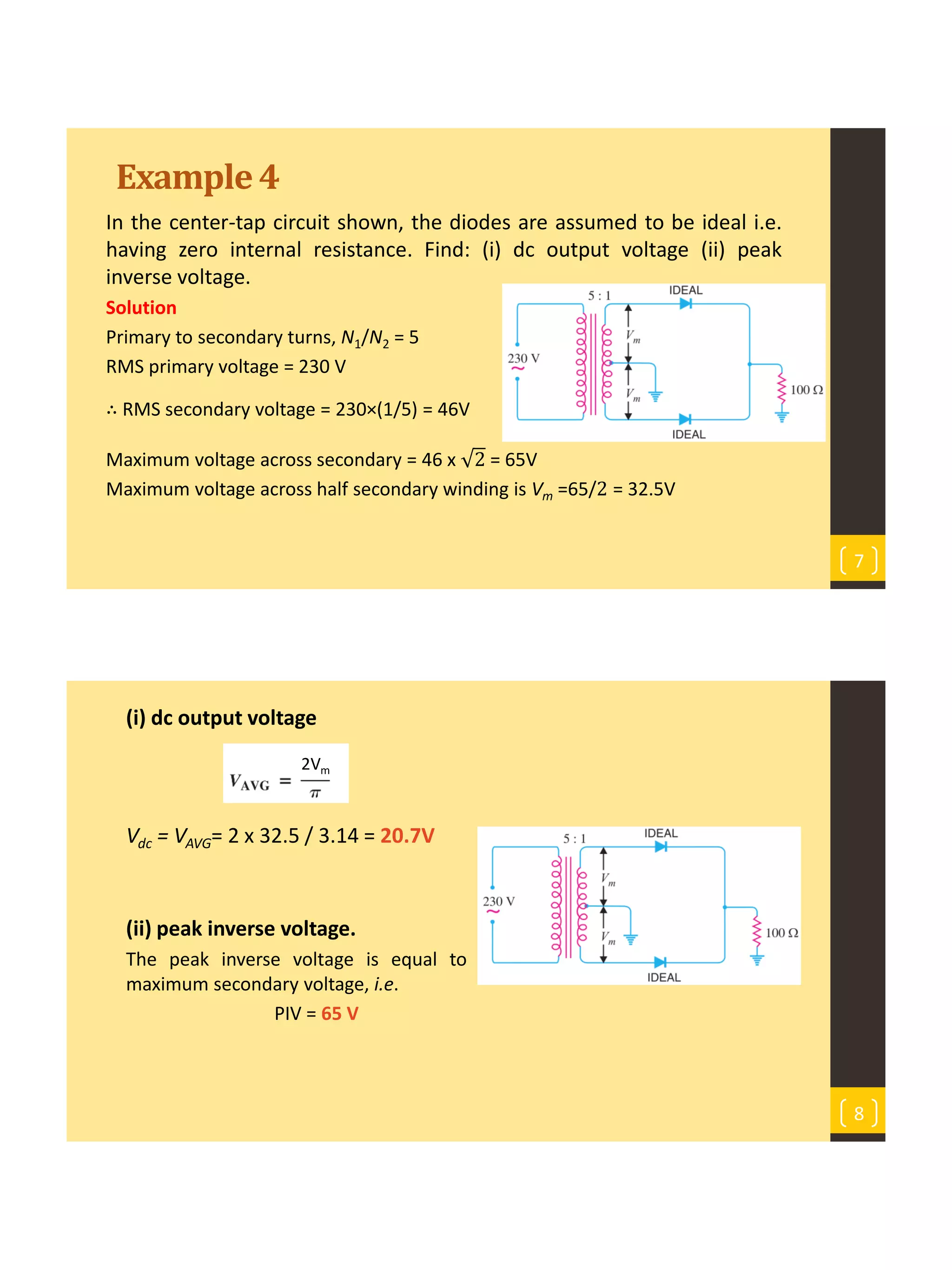
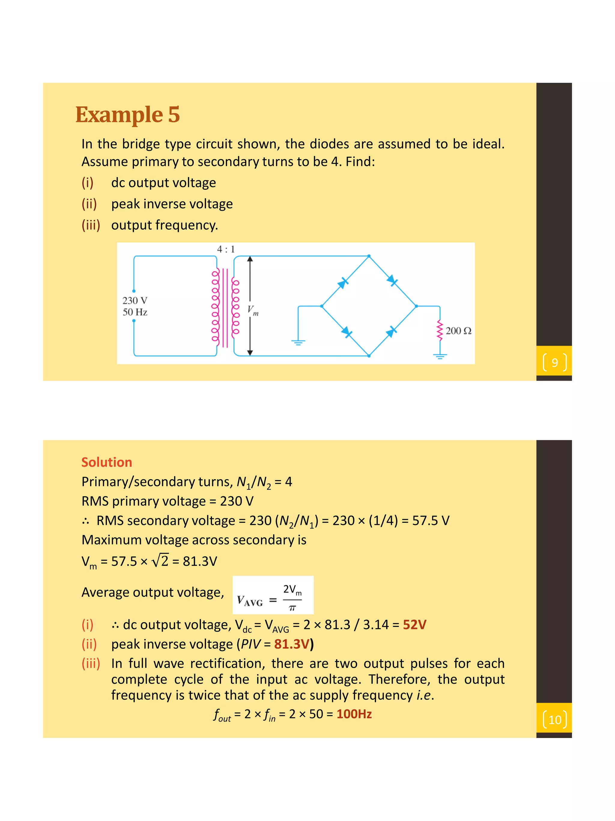
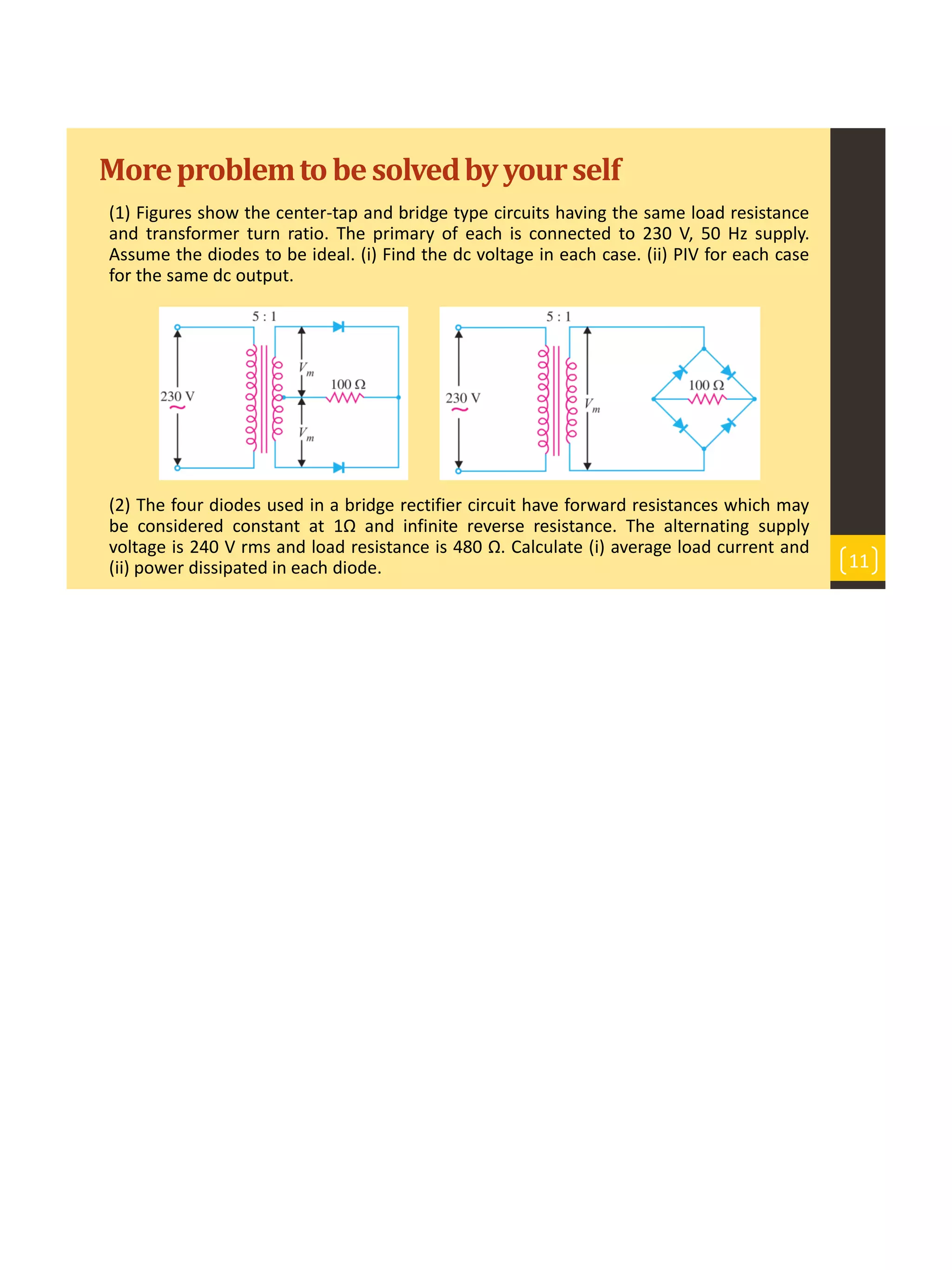
This document discusses diodes and applications of diodes in rectifier circuits. It provides examples of calculating output voltages, currents, and power dissipation in half-wave, full-wave, and bridge rectifier circuits using ideal and practical diode models. Key points covered include:
- Calculating DC output voltage, peak inverse voltage, and load current in half-wave and full-wave rectifiers.
- Using Kirchhoff's laws and diode voltage drops to solve circuits containing multiple diodes.
- Rectifier circuits double the output frequency compared to the input AC supply frequency.
- Practical diodes have forward voltage drops and resistance that must be accounted for in calculations.
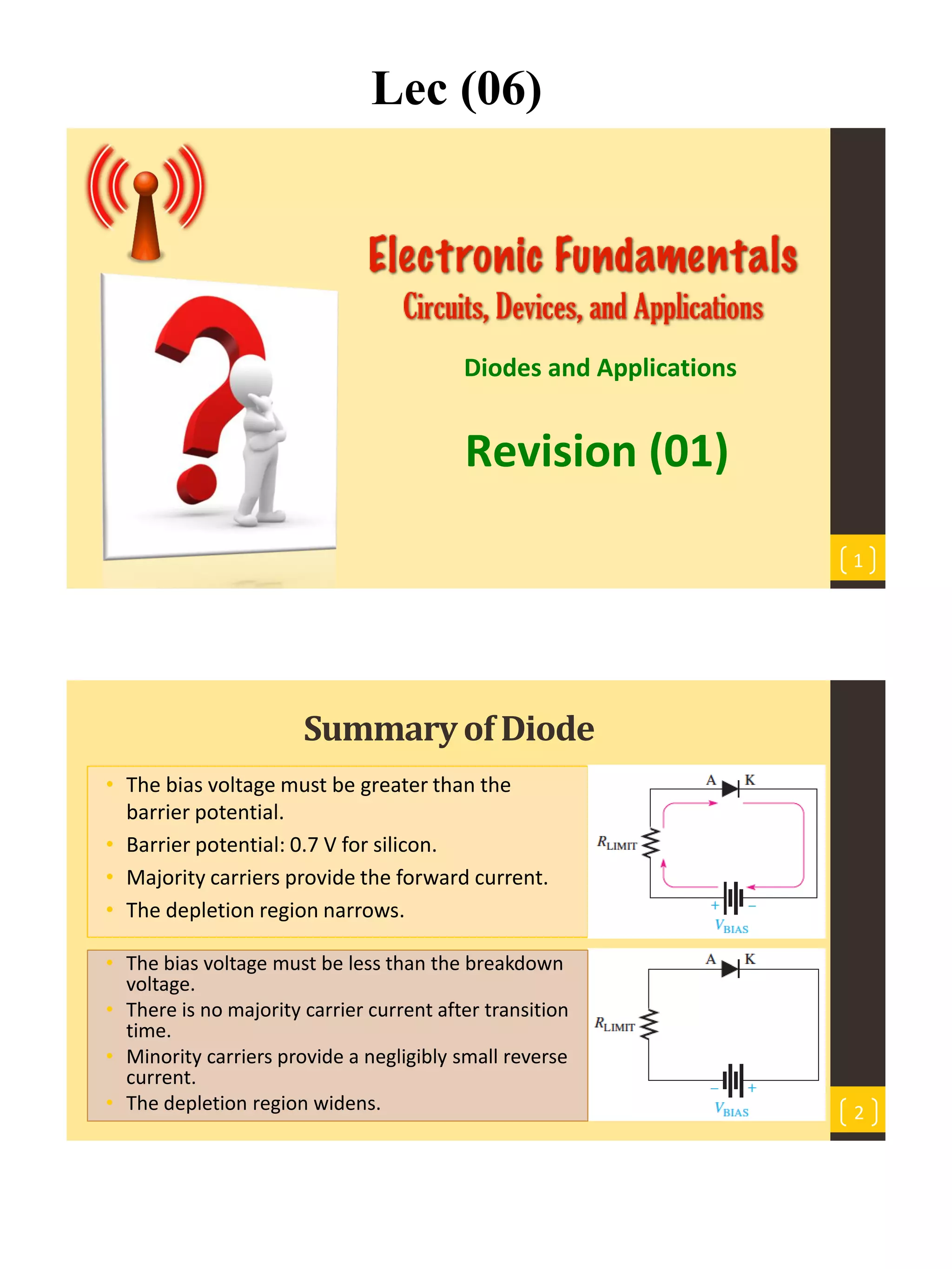
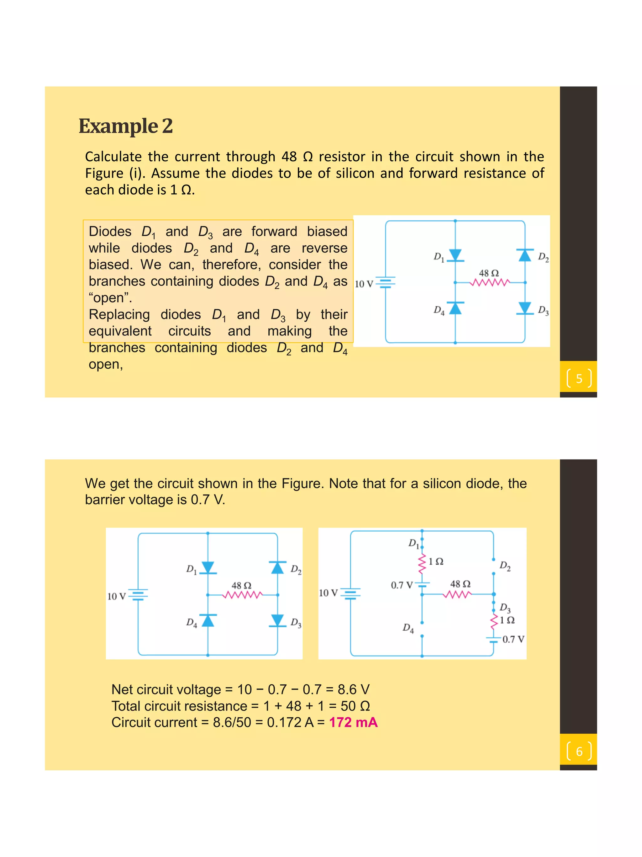
![Example1
An ac voltage of peak value 20 V is connected in series with a silicon
diode and load resistance of 500 Ω. If the forward resistance of the
diode is 10 Ω, find:
• (a) peak current through the diode
• (b) peak output voltage.
What will be these values if the diode is considered as an ideal diode?
3
Solution. The diode will conduct during
the positive half-cycles of ac input
voltage. The equivalent circuit is
(a) peak current through the diode
VF = VPB + (If)peak [rf + RL]
(If)peak =
𝑉𝐹−𝑉𝑃𝐵
𝑟𝑓+𝑅𝐿
=
20−0.7
10+500
= 37.8 mA
4
(b) peak output voltage
Vout = (If)peak x RL = 37.8x10-3A x 500 Ω = 18.9 V
For an ideal diode VPB = 0 and rf = 0
(If)peak =
𝑉𝐹
𝑅𝐿
=
20
500
= 40 mA & Vout = (If)peak x RL = 40x10-3 A x 500 Ω = 20 V](https://image.slidesharecdn.com/lec062017-230529074639-89fc72f1/75/Lec-06-2017-pdf-2-2048.jpg)