Three_Phase_Inverter_in_120_mode.pdf
•
0 likes•12 views

REPORT ON THREE PHASE INVERTER 120 DEG. MODE

Recommended
More Related Content
Similar to Three_Phase_Inverter_in_120_mode.pdf
Similar to Three_Phase_Inverter_in_120_mode.pdf (20)
More from Indian Institute of Technology Guwahati
More from Indian Institute of Technology Guwahati (15)
Recently uploaded
Recently uploaded (20)
Three_Phase_Inverter_in_120_mode.pdf
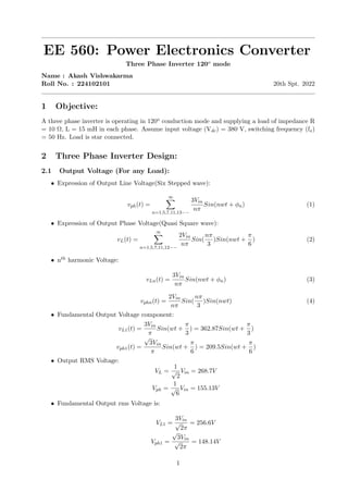
- 1. EE 560: Power Electronics Converter Three Phase Inverter 120o mode Name : Akash Vishwakarma Roll No. : 224102101 20th Spt. 2022 1 Objective: A three phase inverter is operating in 120o conduction mode and supplying a load of impedance R = 10 Ω, L = 15 mH in each phase. Assume input voltage (Vdc) = 380 V, switching frequency (fs) = 50 Hz. Load is star connected. 2 Three Phase Inverter Design: 2.1 Output Voltage (For any Load): • Expression of Output Line Voltage(Six Stepped wave): vph(t) = ∞ X n=1,5,7,11,13−− 3Vin nπ Sin(nwt + ϕn) (1) • Expression of Output Phase Voltage(Quasi Square wave): vL(t) = ∞ X n=1,5,7,11,12−− 2Vin nπ Sin( nπ 3 )Sin(nwt + π 6 ) (2) • nth harmonic Voltage: vLn(t) = 3Vin nπ Sin(nwt + ϕn) (3) vphn(t) = 2Vin nπ Sin( nπ 3 )Sin(nwt) (4) • Fundamental Output Voltage component: vL1(t) = 3Vin π Sin(wt + π 3 ) = 362.87Sin(wt + π 3 ) vph1(t) = √ 3Vin π Sin(wt + π 6 ) = 209.5Sin(wt + π 6 ) • Output RMS Voltage: VL = 1 √ 2 Vin = 268.7V Vph = 1 √ 6 Vin = 155.13V • Fundamental Output rms Voltage is: VL1 = 3Vin √ 2π = 256.6V Vph1 = √ 3Vin √ 2π = 148.14V 1
- 2. 2.2 Load Current (For any load) • Expression for load current: iL(t) = iph(t) = ∞ X n=1,5,7,11,12−− 2Vin nπ|Zn| Sin( nπ 3 )Sin(nwt + π 6 − ϕn) (5) • nth harmonic Current iLn(t) = iphn(t) = 2Vin nπ|Zn| Sin( nπ 3 )Sin(nwt + π 6 − ϕn) • where Zn is nth order impedance Zn = R + jnwL (6) • Fundamental Load Current Component is: io1(t) = 32.83sin(wt − 25.23o ) • Load current (RMS): Iphr = p Iph1 + Iph5 + Iph37 − −− = 23.5A 2.3 Total Harmonic Distortion and Distortion Factor in Output Voltage • Distortion Factor g = VL1 VLr = Vph1 Vphr = 0.95 (7) • Total Harmonic Distortion THD = r 1 g2 − 1 ∗ 100 = 31% (8) 2
- 3. 2.4 Simulation model of Three Phase Inverter 120o mode 3
- 4. 3 Waveforms and Results: 4