2. At a glance….
• Definition
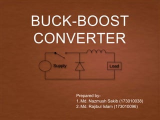
• Operational circuit of Buck-boost converter
• Duty ratio
• Voltage Across Inductor
• Applications
3. What is Buck-Boost Converter
• The buck–boost converter is a type of DC-to-DC
converter that has an output voltage magnitude that
is either greater than or less than the input voltage
magnitude. It is equivalent to a flyback converter
using a single inductor instead of a transformer.
4. Topology
The output voltage is of the opposite polarity than
the input. This is a switched-mode power supply
with a similar circuit topology to the boost converter
and the buck converter. The output voltage is
adjustable based on the duty cycle of the switching
transistor. One possible drawback of this converter
is that the switch does not have a terminal at
ground; this complicates the driving circuitry.
However, this drawback is of no consequence if the
power supply is isolated from the load circuit (if, for
example, the supply is a battery) because the
supply and diode polarity can simply be reversed.
When they can be reversed, the switch can be on
either the ground side or the supply side.
6. OPERATIONS OF CIRCUIT
• Step 1: when MOSFET is ON
• Voltage across inductor L is equal to V (source voltage)
7. • Step 2: When MOSFET is OFF
• Voltage across inductor L is equal to Vo (in reverse
direction)
• Here output voltage developed across load is Vo
8. • Step 3: when MOSFET is ON in next cycle
Load is isolated from voltage source
In this case charged capacitor across load will
maintain voltage across load
9. DUTY RATIO
• Duty ratio D is defined as Ton/T
Here, Ton=ON time
T= time period of gate signal
• So, D= Ton/T
Ton=D*T---eq(1)
• T=Ton+Toff-----eq(2)
Toff=(1-D)T
10. VOLTAGE ACROSS INDUCTOR
• When mosfet is ON, voltage across inductor is equal to source
voltage (V)
• When mosfet is OFF, voltage across inductor is equal to output
voltage (V)
• As average voltage across inductor is zero
Hence,
V*D*T=Vo*(1-D)*T
Vo=V* D/1-D
11. • This equation shows that output voltage depends on
duty ratio(D)
• For buck operation
Duty Ratio, D=0 to 0.5
• For boost operation
Duty Ratio, D =0.5 to 1
12. APPLICATION
• Used in many industrial applications such as subway
cars, trolly buses, battery operated vehicles, battery
charging etc.
• To provide smooth control on output, high efficiency,
fast response and regeneration.
• To provide efficient control on dc motor operation
• To provide long life and less maintenance due to
absence of moving parts.