This document discusses laminar and turbulent fluid flow in pipes. It defines laminar flow as smooth, ordered motion of fluid layers and turbulent flow as irregular motion with velocity fluctuations. The Reynolds number determines the flow regime, with laminar flow below 2000 and turbulent flow above 4000. For fully developed laminar pipe flow, the velocity profile is parabolic and the pressure drop is proportional to flow rate, pipe length, and fluid viscosity, inversely proportional to pipe diameter raised to the fourth power.
Preet Kumar, an M.Tech student at IIT Roorkee, introduces the topic of fluid dynamics.
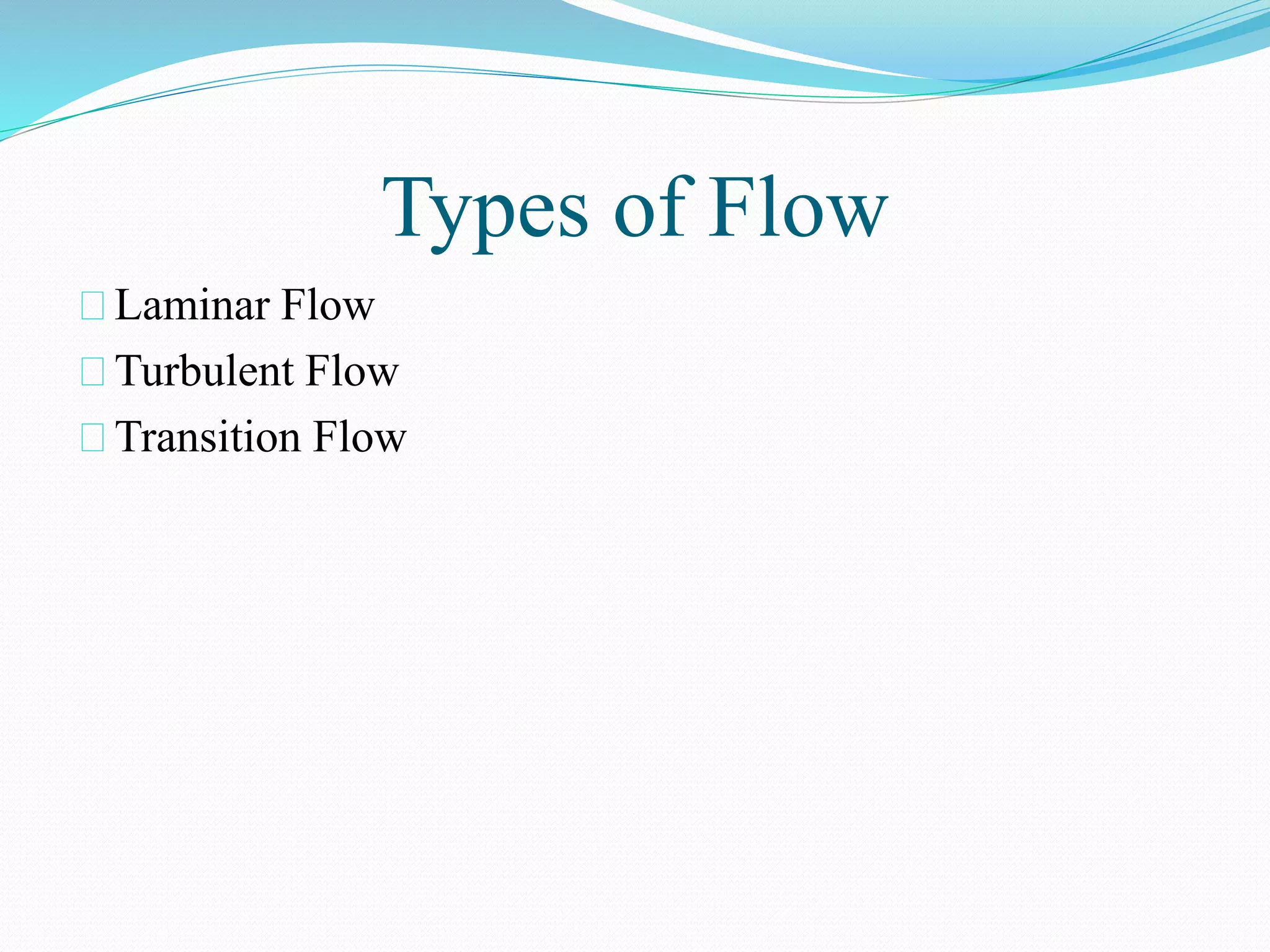
Discusses laminar, turbulent, and transition flow. Key characteristics: laminar is smooth and ordered, turbulent has fluctuations and is disordered.
Principles of fluid flow in pipes, defining laminar and turbulent flows, and introducing the Reynolds number for flow prediction.
Explains Bernoulli's equation connecting fluid velocity, pressure, and height. Relevant for measuring flow rates using conservation of mass.
Distinguishes between compressible and incompressible flow. Most liquids are incompressible while gases can be compressible but sometimes approximated as incompressible.
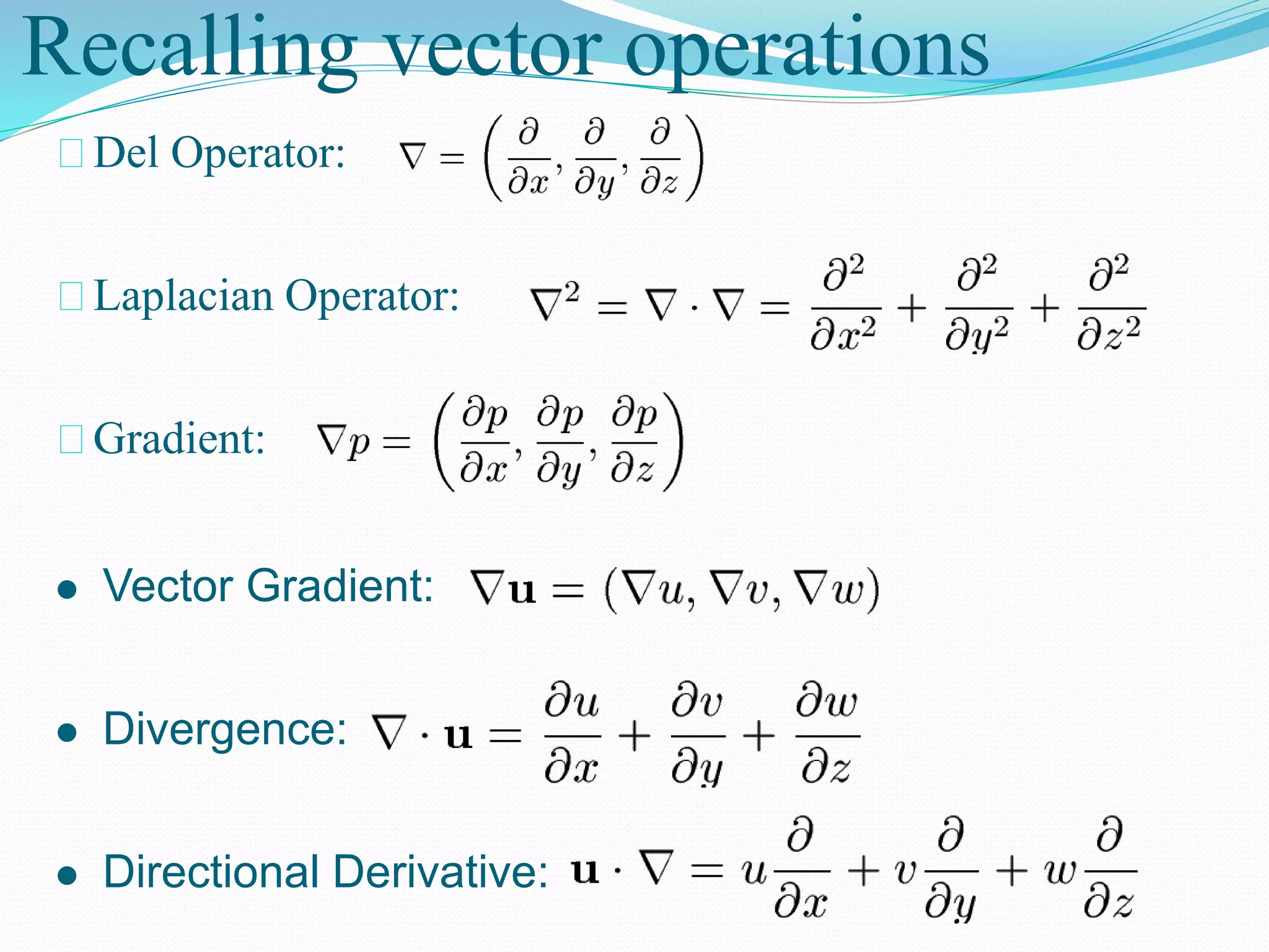
Recalls vector operations useful in fluid dynamics: Del Operator, Divergence, Gradient, and Directional Derivative.
Discusses conservation of momentum in fluid elements, detailing normal and shear stresses along with deriving differential momentum equations.
Presents Euler’s equations for inviscid flow and links to the derivation of Bernoulli’s equation.
Details the continuity equation for incompressible flow and introduces Navier-Stokes equations related to momentum conservation.
Breaks down the Navier-Stokes equations into acceleration, advection, diffusion, pressure, and body force terms.
Examines continuity and Navier-Stokes equations in Cartesian and cylindrical coordinates for incompressible flow.
Explains steady, incompressible flow in a circular pipe, defining the velocity profile and conditions for fully developed laminar flow.
Discusses the pressure drop due to viscous effects in laminar flow, introducing Poiseuille's law and its implications for pipe flow.
motion
flow in laminar
6
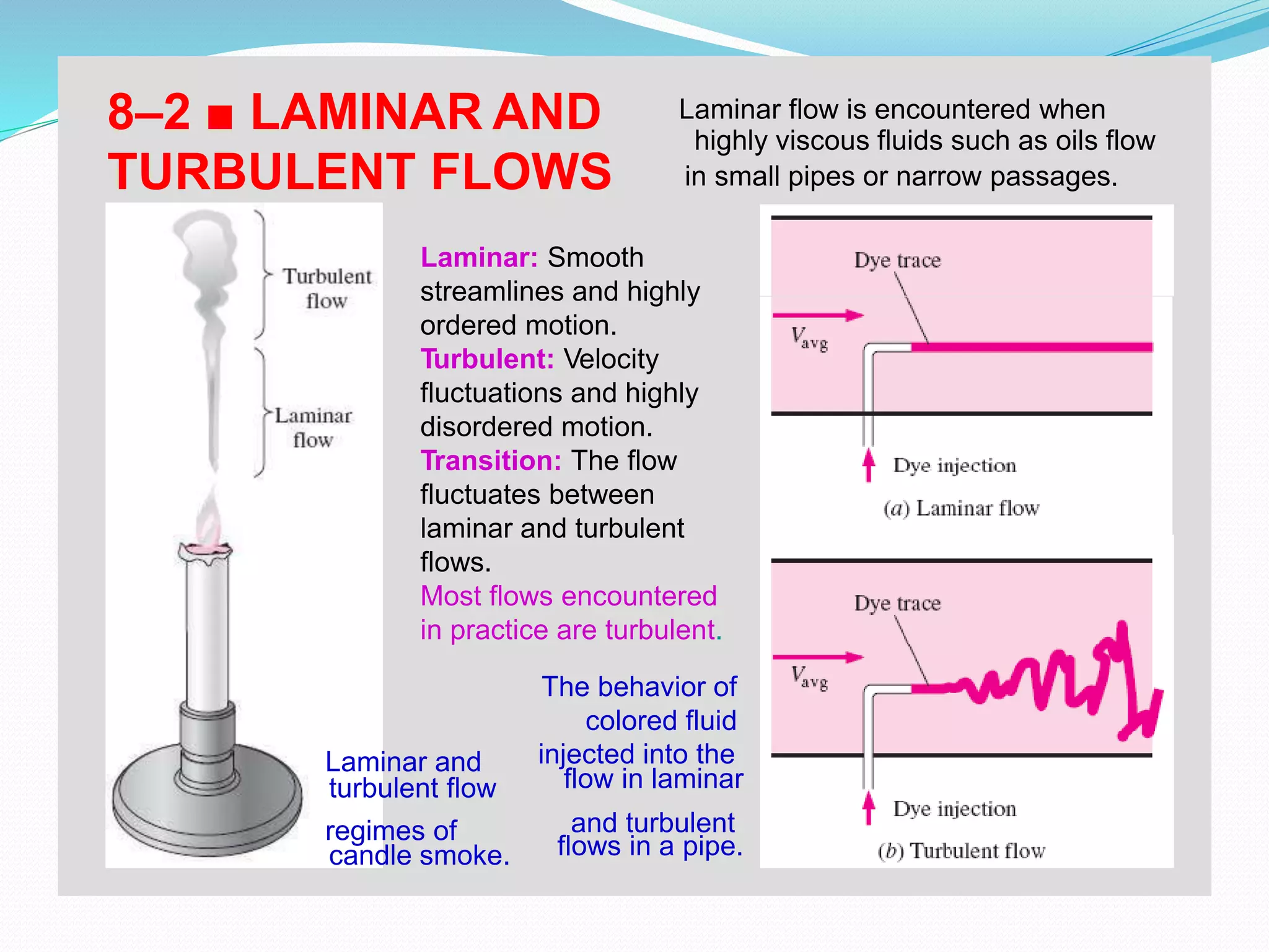
highlyviscous fluids such as oils flow
flow in laminarturbulent flow
flows in a pipe.candle smoke.
8–2 ■ LAMINAR AND Laminar flow is encountered when
TURBULENT FLOWS in small pipes or narrow passages.
Laminar: Smooth
streamlines and highly
ordered motion.
Turbulent: Velocity
fluctuations and highly
disordered motion.
Transition: The flow
fluctuates between
laminar and turbulent
flows.
Most flows encountered
in practice are turbulent.
The behavior of
colored fluid
Laminar and injected into the
regimes of and turbulent
4.
Principles of FluidFlow in Pipes
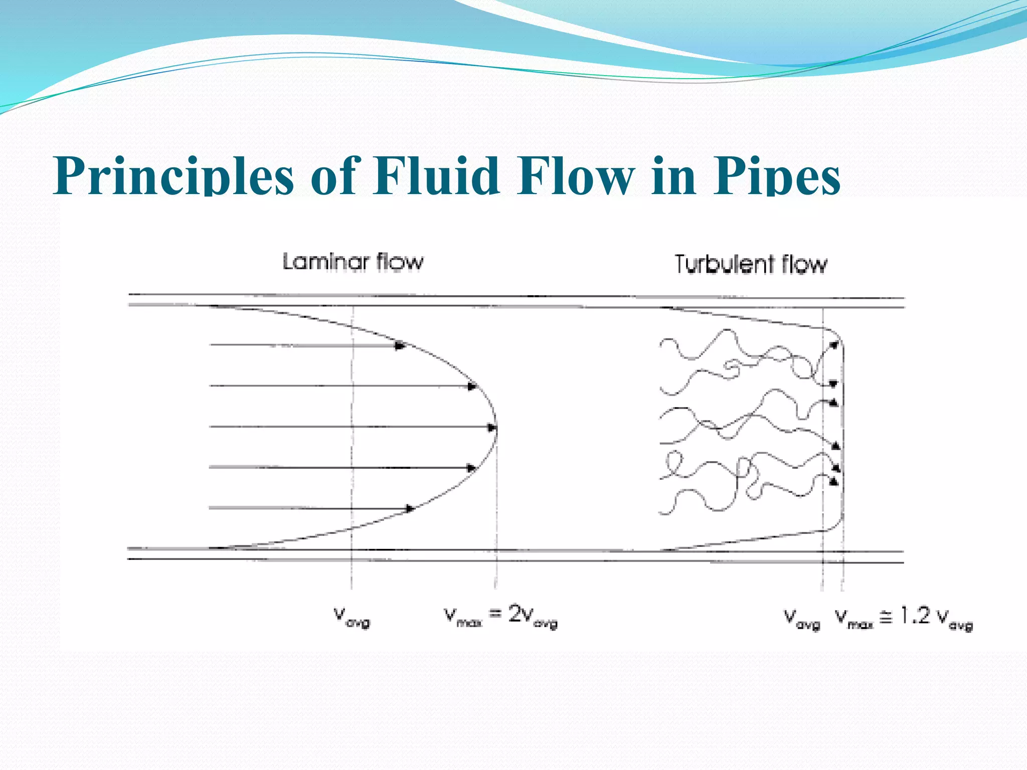
In laminar flow , the fluid travels as parallel layers (known as
streamlines) that do not mix as they move in the direction of
the flow.
If the flow is turbulent, the fluid does not travel in parallel
layers, but moves in a haphazard manner with only the average
motion of the fluid being parallel to the axis of the pipe.
If the flow is transitional , then both types may be present at
different points along the pipeline or the flow may switch
between the two.
In 1883, Osborne Reynolds performed a classic set of
experiments that showed that the flow characteristic can be
predicted using a dimensionless number, now known as the
Reynolds number.
5.
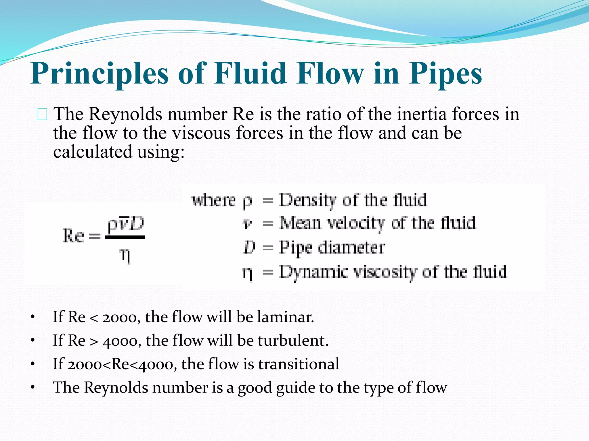
Principles of FluidFlow in Pipes
The Reynolds number Re is the ratio of the inertia forces in
the flow to the viscous forces in the flow and can be
calculated using:
• If Re < 2000, the flow will be laminar.
• If Re > 4000, the flow will be turbulent.
• If 2000<Re<4000, the flow is transitional
• The Reynolds number is a good guide to the type of flow
Principles of FluidFlow in Pipes
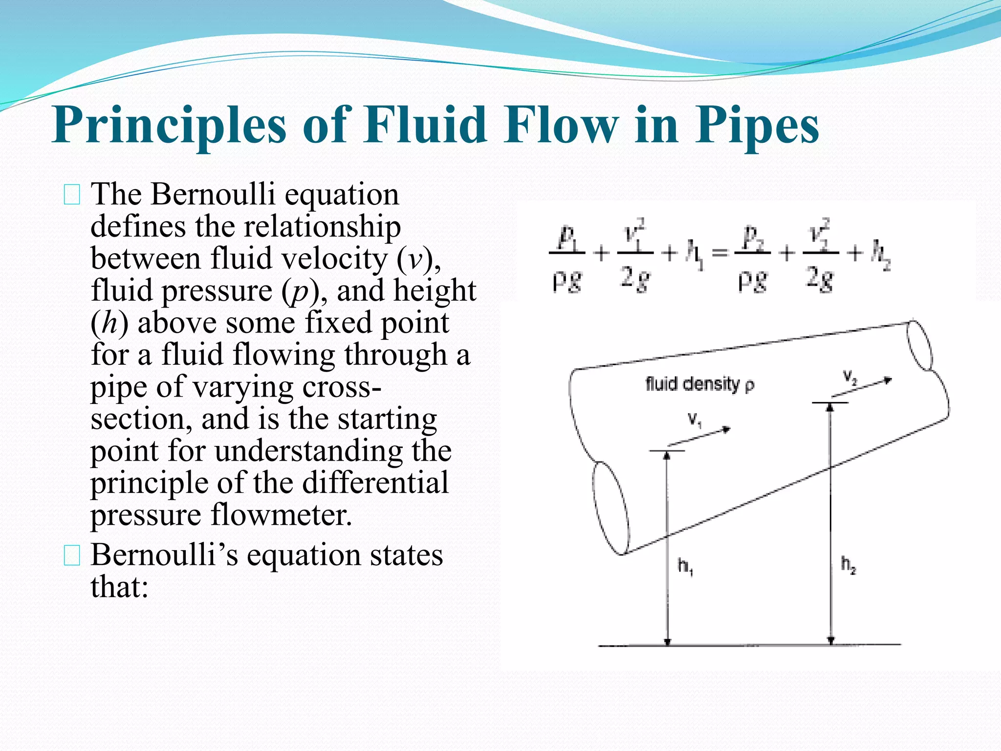
The Bernoulli equation
defines the relationship
between fluid velocity (v),
fluid pressure (p), and height
(h) above some fixed point
for a fluid flowing through a
pipe of varying cross-
section, and is the starting
point for understanding the
principle of the differential
pressure flowmeter.
Bernoulli’s equation states
that:
8.
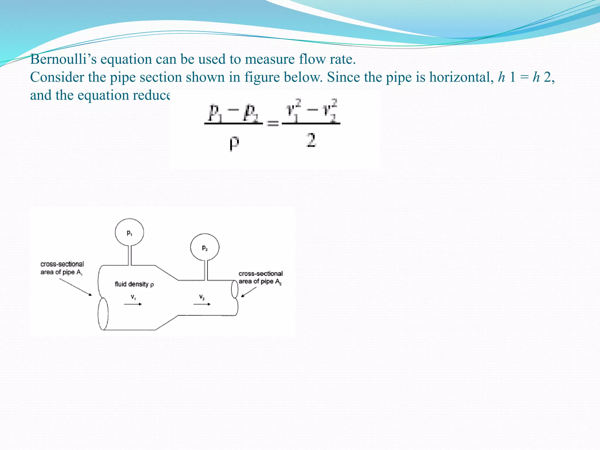
Bernoulli’s equation canbe used to measure flow rate.
Consider the pipe section shown in figure below. Since the pipe is horizontal, h 1 = h 2,
and the equation reduces to:
9.
Principles of FluidFlow in Pipes
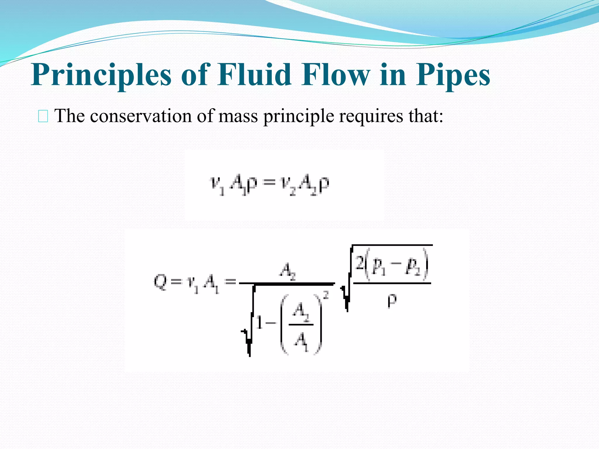
The conservation of mass principle requires that:
10.
Compressible or Incompressible
FluidFlow
Most liquids are nearly incompressible; that is, the density of a liquid remains
almost constant as the pressure changes.
To a good approximation, then, liquids flow in an incompressible manner.
In contrast, gases are highly compressible. However, there are situations in
which the density of a flowing gas remains constant enough that the flow can
be considered incompressible.
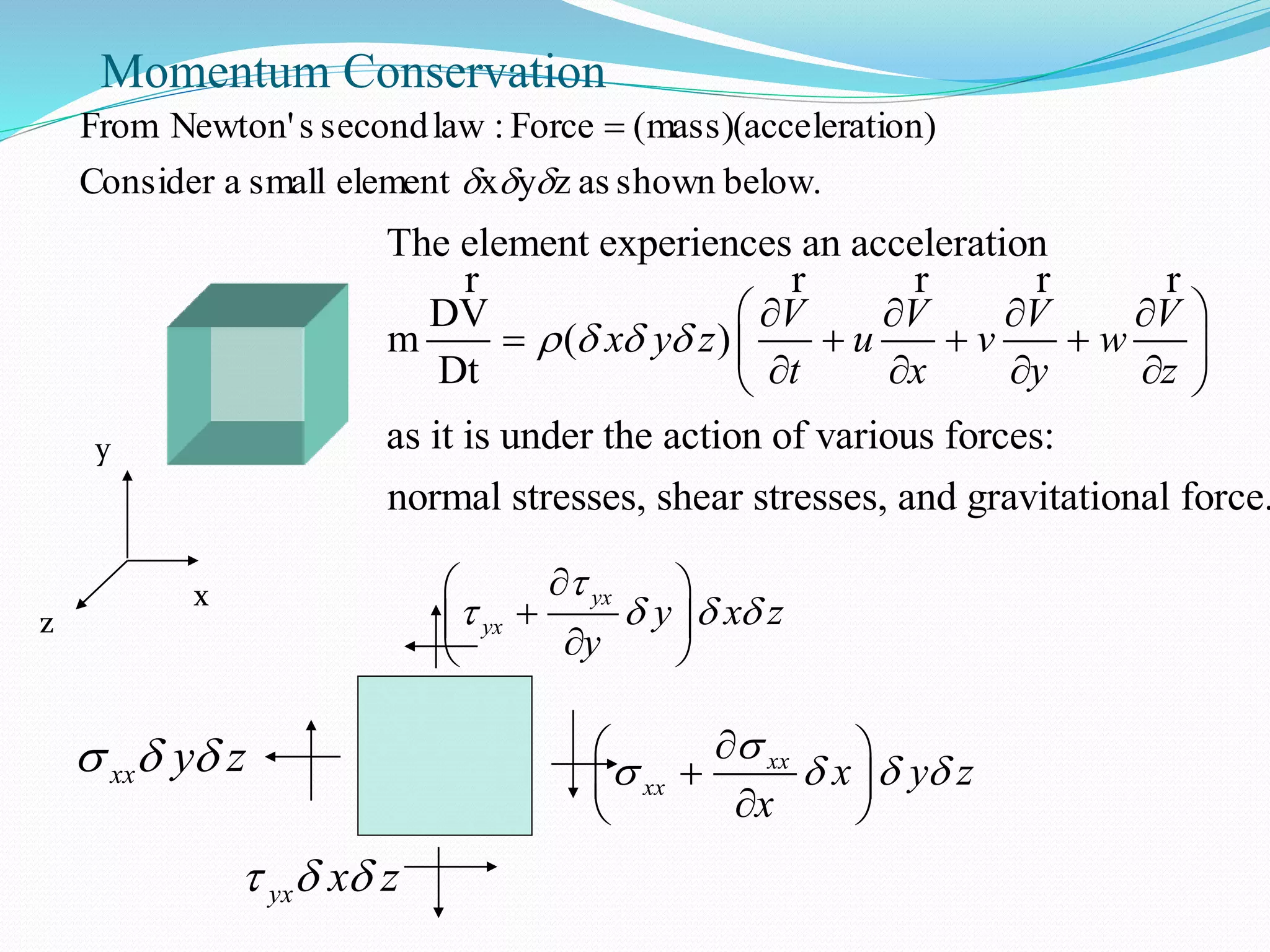
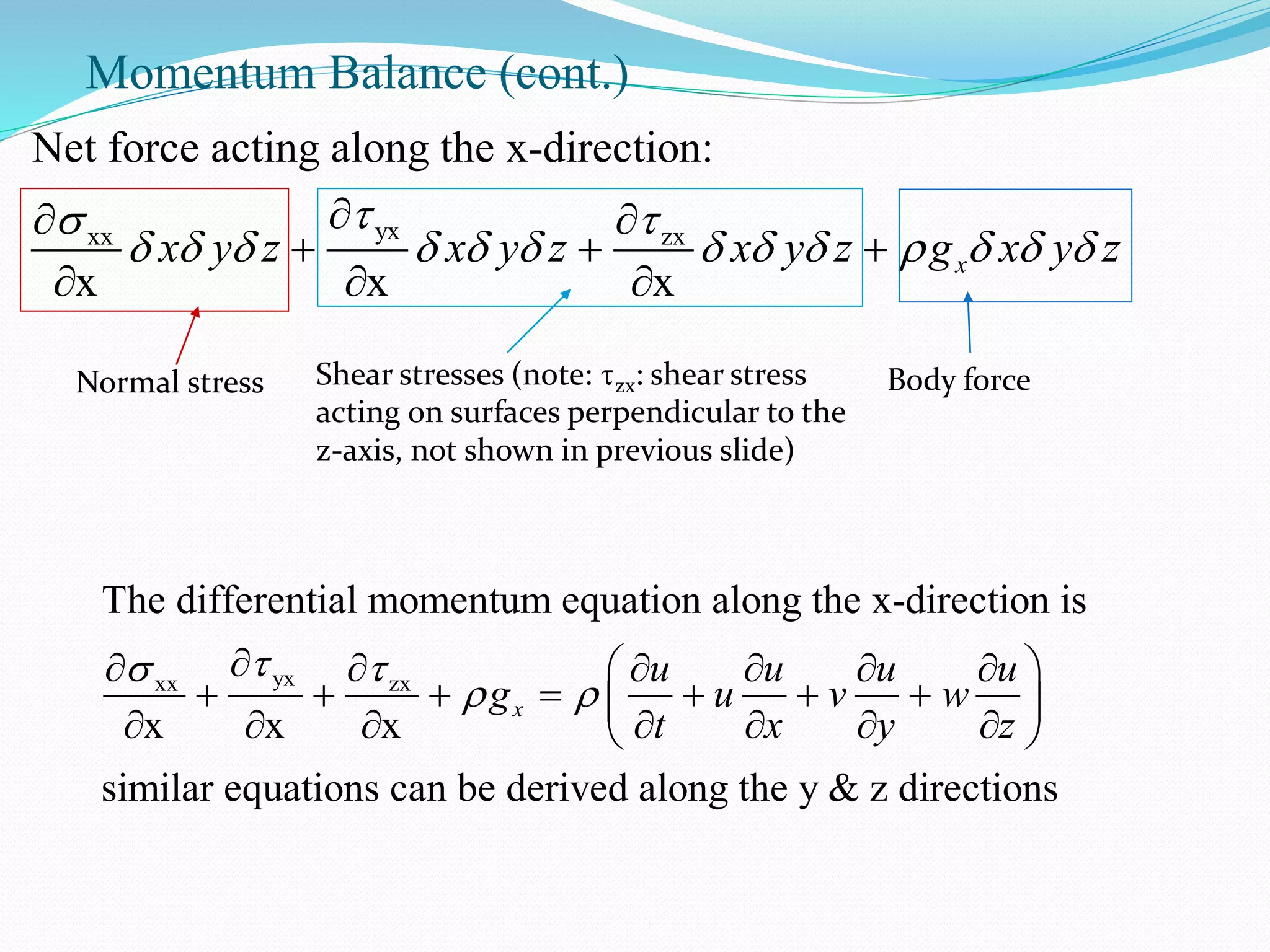
Momentum Balance (cont.)
yxxxzx
Net force acting along the x-direction:
x x x
xx y z x y z x y z g x y z
Normal stress Shear stresses (note: zx: shear stress
acting on surfaces perpendicular to the
z-axis, not shown in previous slide)
Body force
yxxx zx
The differential momentum equation along the x-direction is
x x x
similar equations can be derived along the y & z directions
x
u u u u
g u v w
t x y z
14.
Euler’s Equations
xx yyzz
For an inviscid flow, the shear stresses are zero and the normal stresses
are simply the pressure: 0 for all shear stresses,
x
Similar equations for
x
P
P u u u u
g u v w
t x y z
y & z directions can be derived
y
z
y
z
P v v v v
g u v w
t x y z
P w w w w
g u v w
t x y z
Note: Integration of the Euler’s equations along a streamline will give rise to the
Bernoulli’s equation.
15.
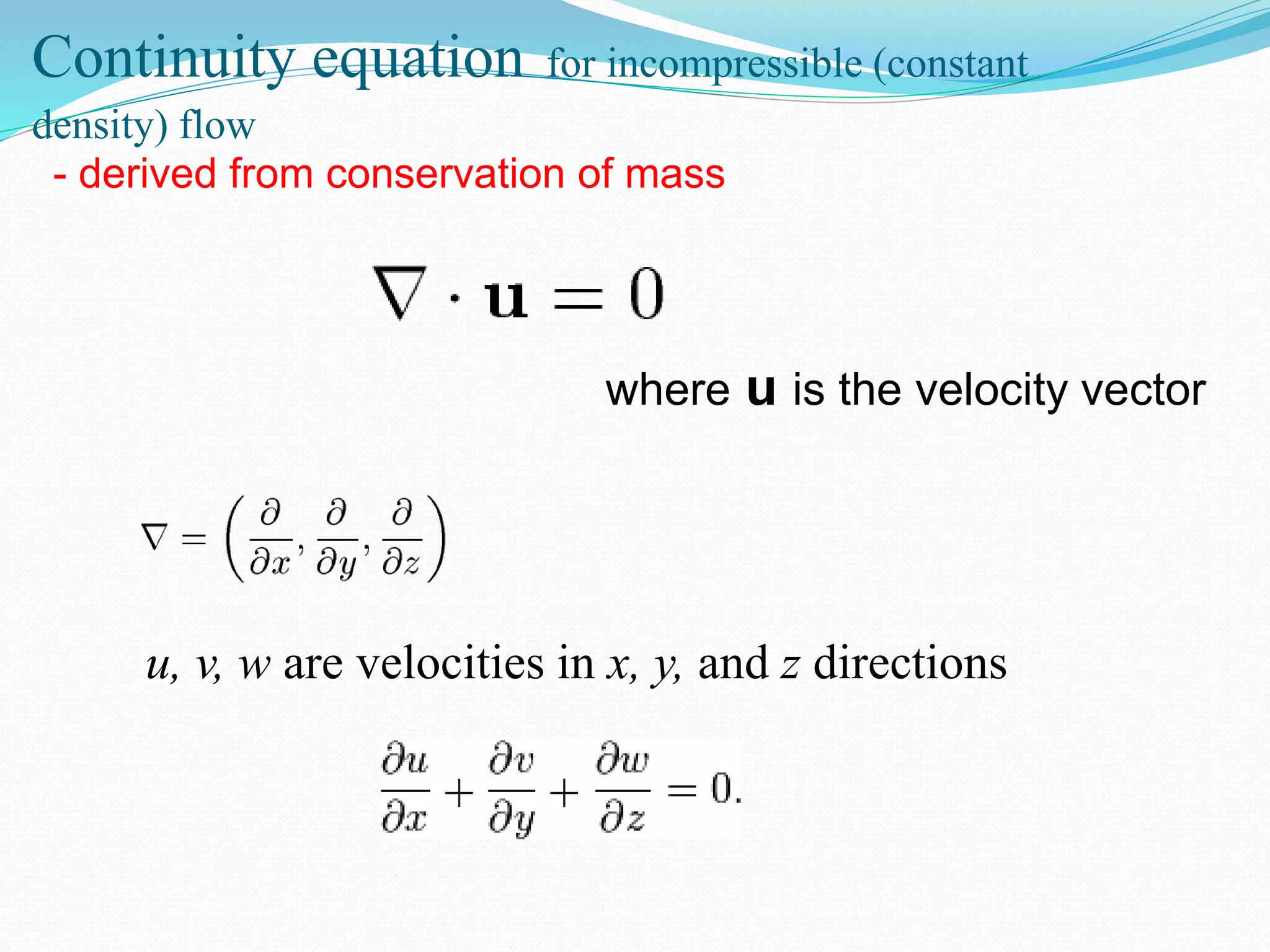
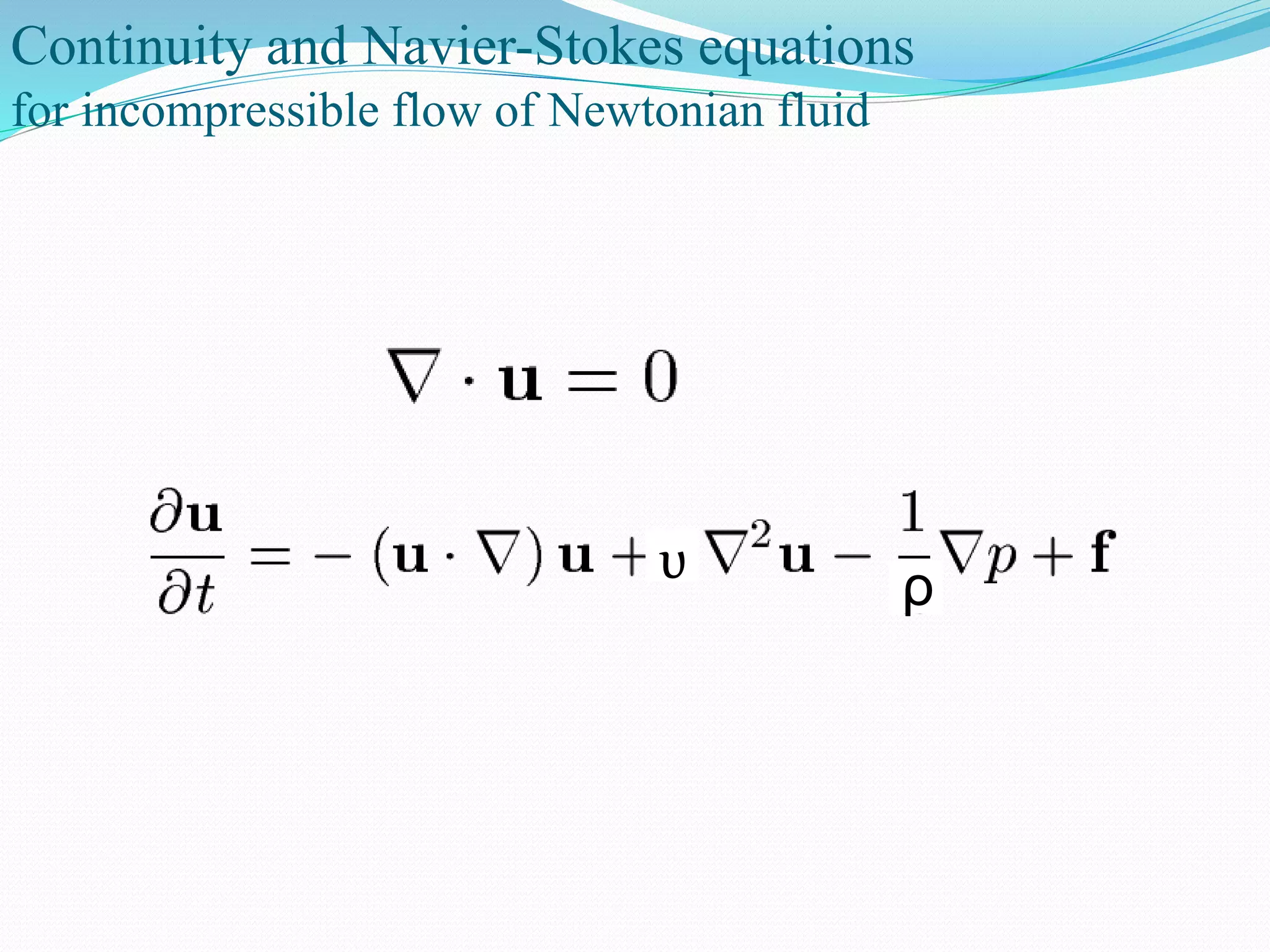
Continuity equation forincompressible (constant
density) flow
where u is the velocity vector
u, v, w are velocities in x, y, and z directions
- derived from conservation of mass
16.
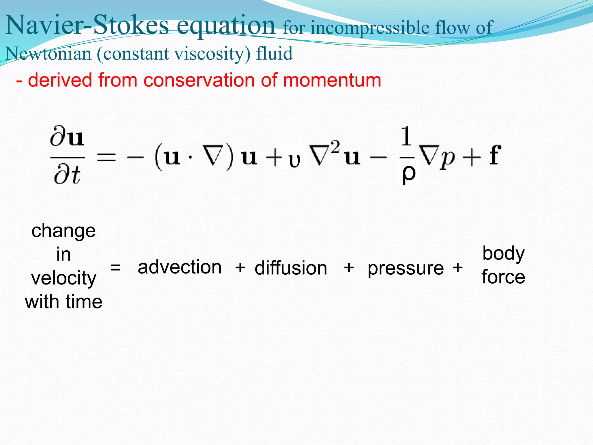
ρυ
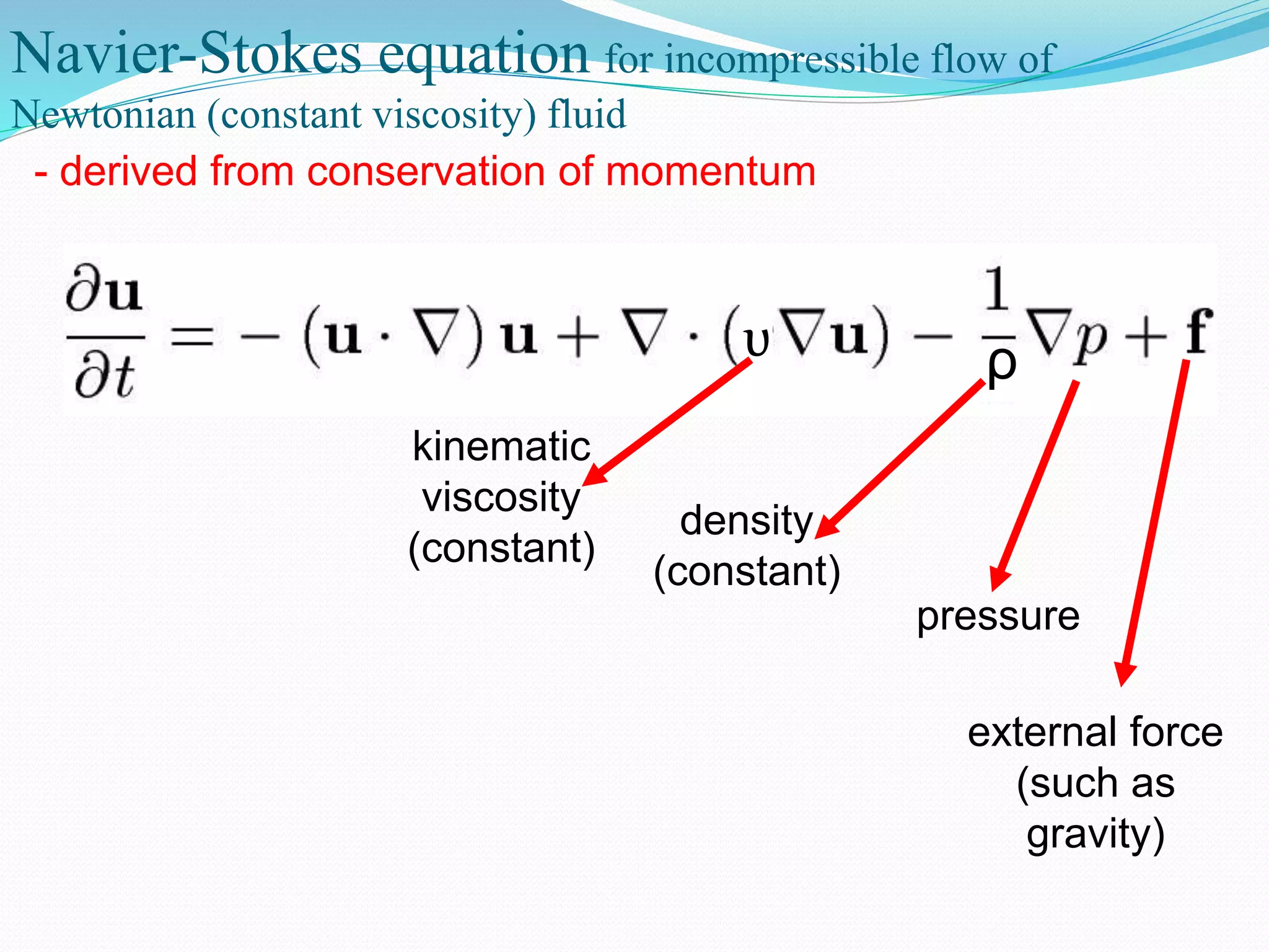
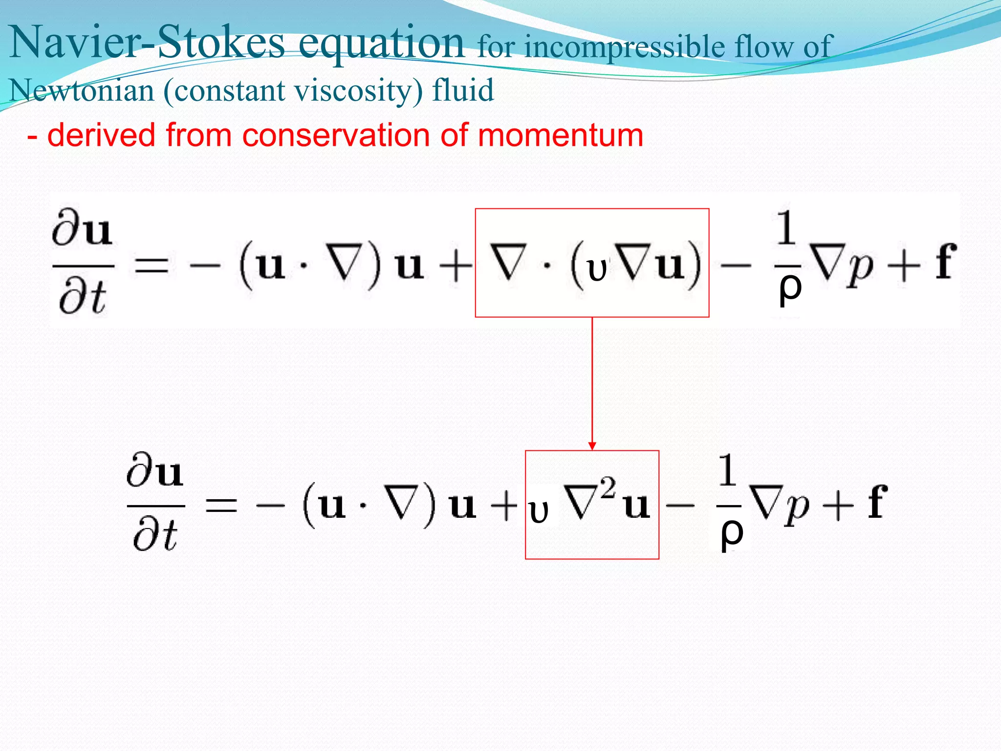
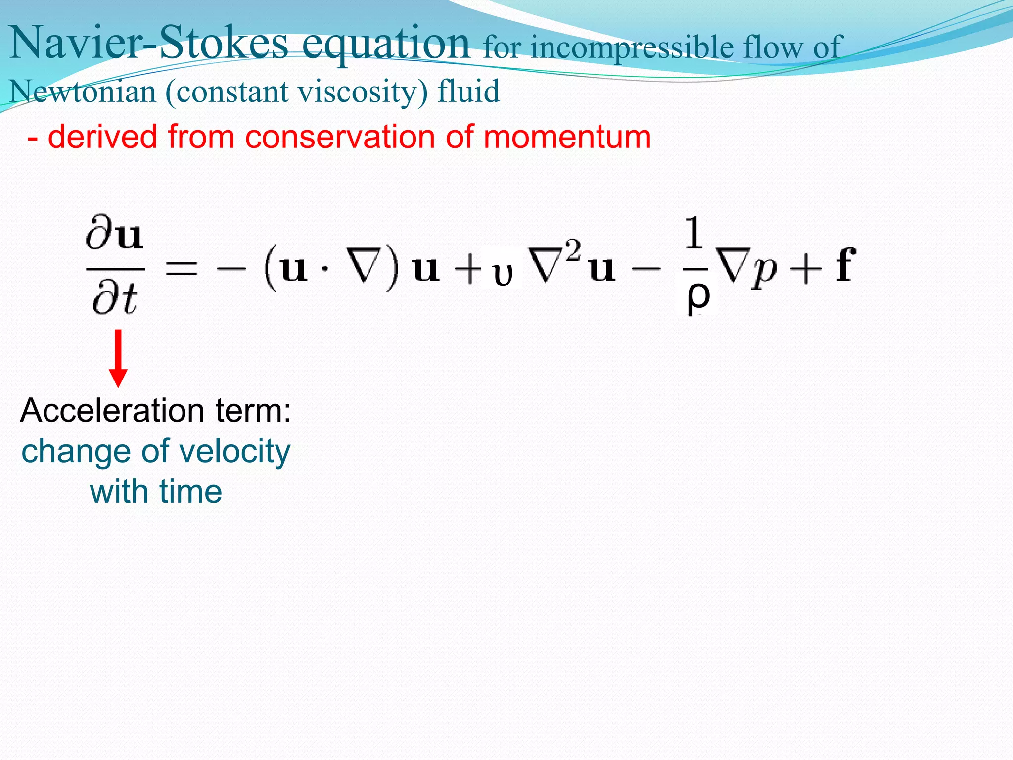
Navier-Stokes equation forincompressible flow of
Newtonian (constant viscosity) fluid
- derived from conservation of momentum
kinematic
viscosity
(constant)
density
(constant)
pressure
external force
(such as
gravity)
17.
Navier-Stokes equation forincompressible flow of
Newtonian (constant viscosity) fluid
- derived from conservation of momentum
ρυ
ρυ
18.
Navier-Stokes equation forincompressible flow of
Newtonian (constant viscosity) fluid
- derived from conservation of momentum
ρυ
Acceleration term:
change of velocity
with time
19.
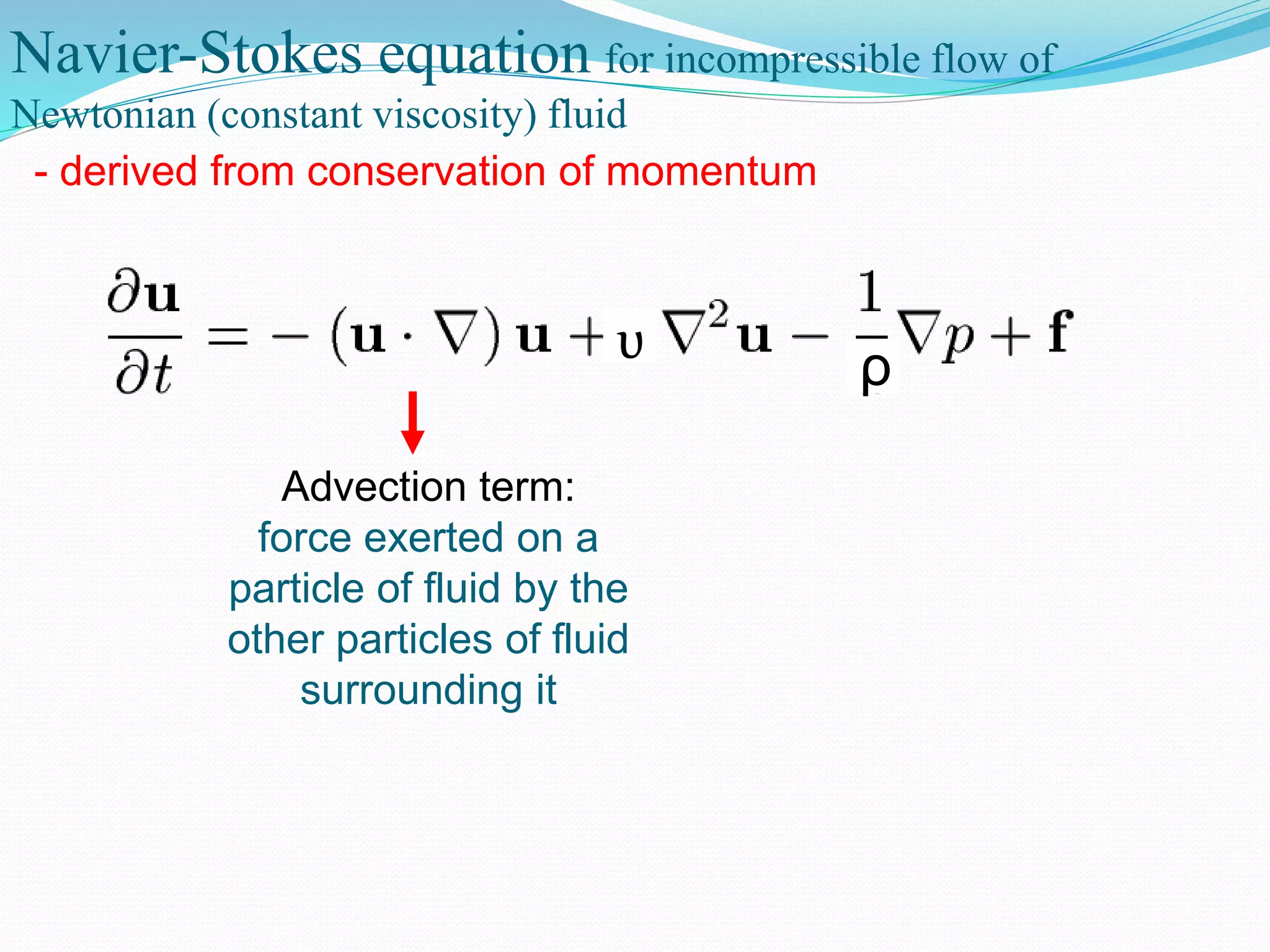
Navier-Stokes equation forincompressible flow of
Newtonian (constant viscosity) fluid
- derived from conservation of momentum
ρυ
Advection term:
force exerted on a
particle of fluid by the
other particles of fluid
surrounding it
20.
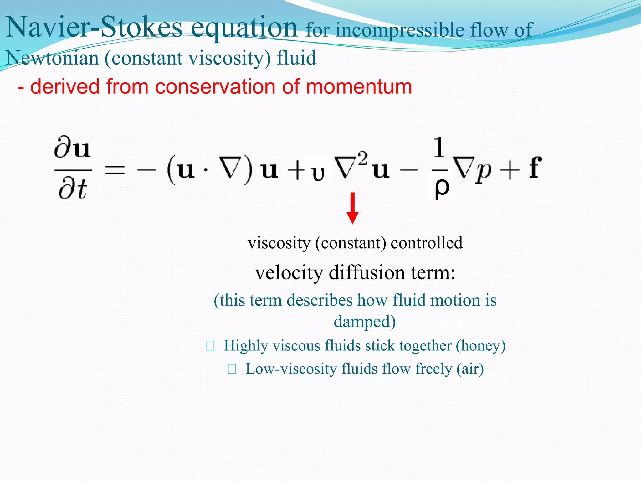
Navier-Stokes equation forincompressible flow of
Newtonian (constant viscosity) fluid
viscosity (constant) controlled
velocity diffusion term:
(this term describes how fluid motion is
damped)
Highly viscous fluids stick together (honey)
Low-viscosity fluids flow freely (air)
- derived from conservation of momentum
ρυ
21.
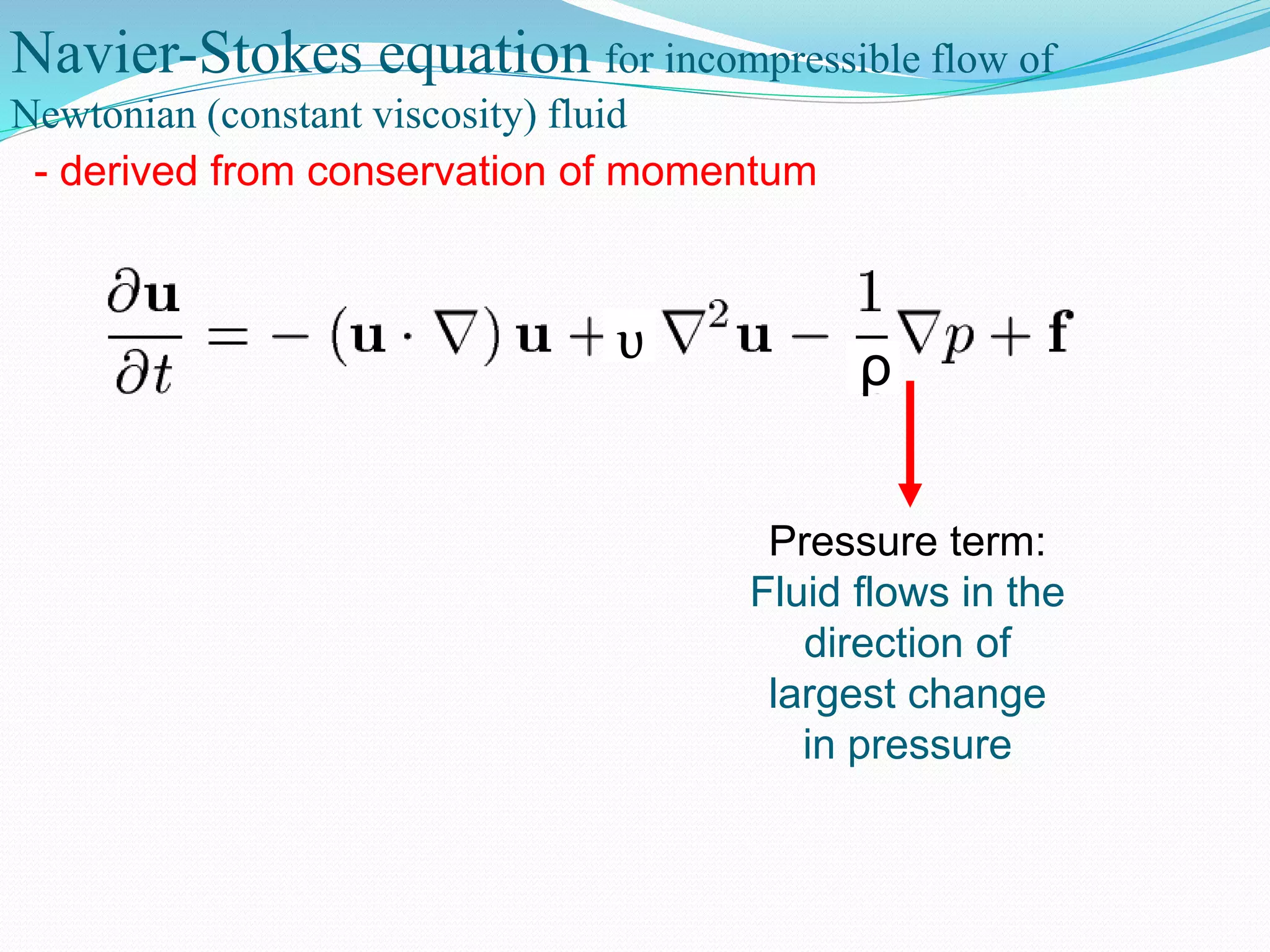
Navier-Stokes equation forincompressible flow of
Newtonian (constant viscosity) fluid
- derived from conservation of momentum
ρυ
Pressure term:
Fluid flows in the
direction of
largest change
in pressure
22.
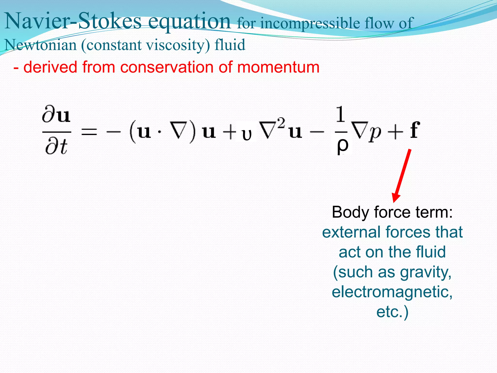
Navier-Stokes equation forincompressible flow of
Newtonian (constant viscosity) fluid
- derived from conservation of momentum
ρυ
Body force term:
external forces that
act on the fluid
(such as gravity,
electromagnetic,
etc.)
23.
Navier-Stokes equation forincompressible flow of
Newtonian (constant viscosity) fluid
- derived from conservation of momentum
ρυ
change
in
velocity
with time
advection diffusion pressure
body
force= + + +
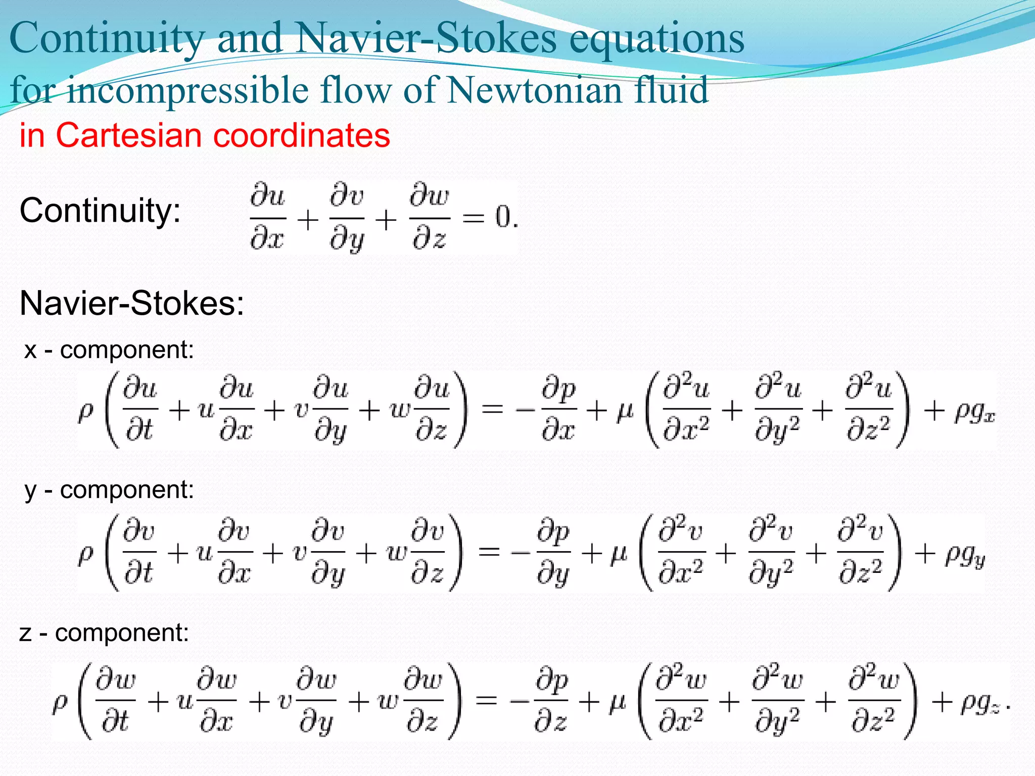
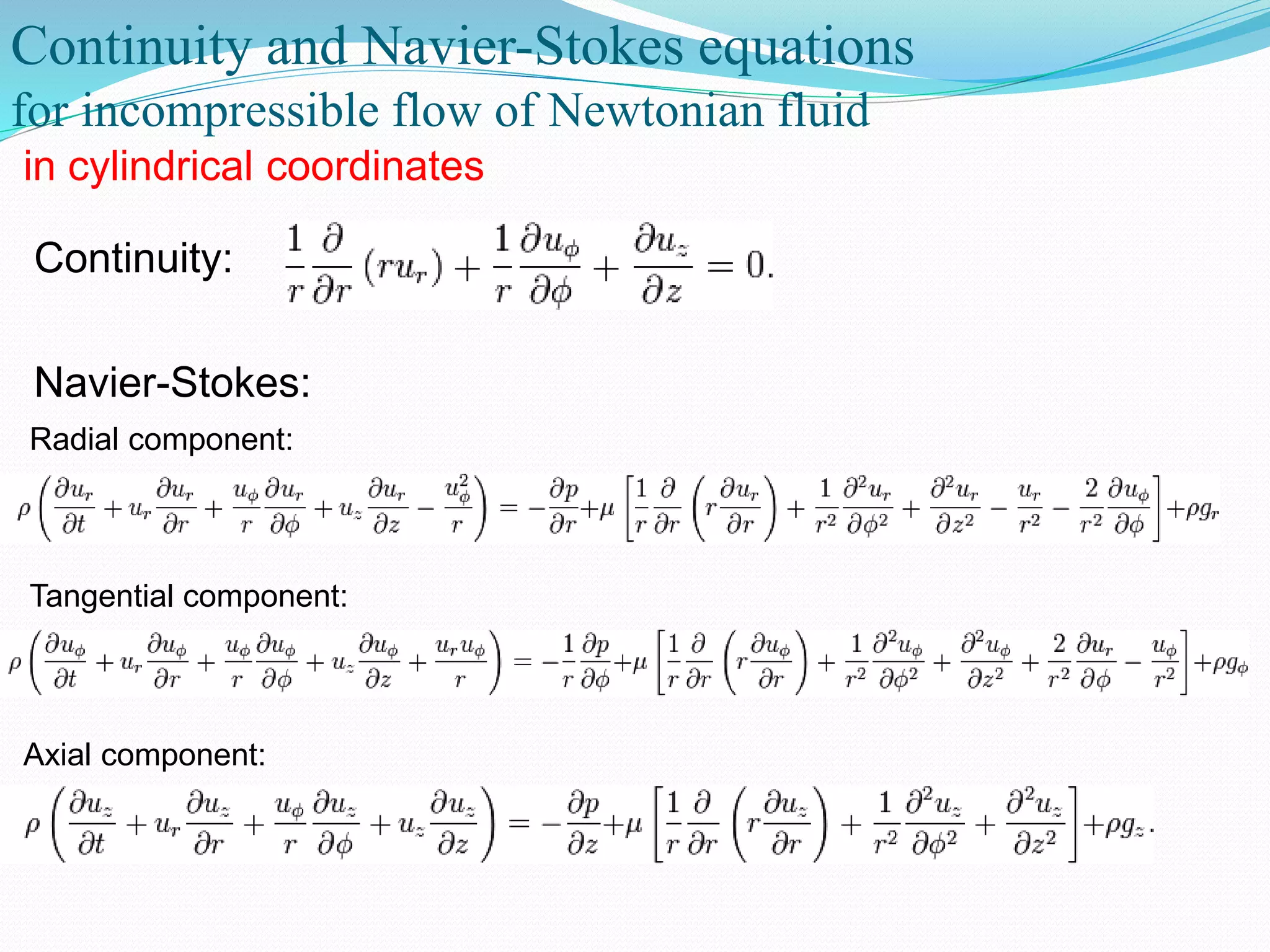
Continuity and Navier-Stokesequations
for incompressible flow of Newtonian fluid
in Cartesian coordinates
Continuity:
Navier-Stokes:
x - component:
y - component:
z - component:
26.
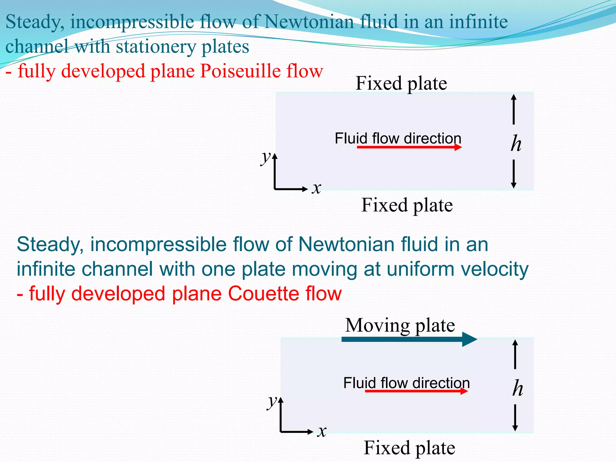
Steady, incompressible flowof Newtonian fluid in an infinite
channel with stationery plates
- fully developed plane Poiseuille flow
Fixed plate
Fixed plate
Fluid flow direction h
x
y
Steady, incompressible flow of Newtonian fluid in an
infinite channel with one plate moving at uniform velocity
- fully developed plane Couette flow
Fixed plate
Moving plate
h
x
y
Fluid flow direction
27.
Continuity and Navier-Stokesequations
for incompressible flow of Newtonian fluid
in cylindrical coordinates
Continuity:
Navier-Stokes:
Radial component:
Tangential component:
Axial component:
28.
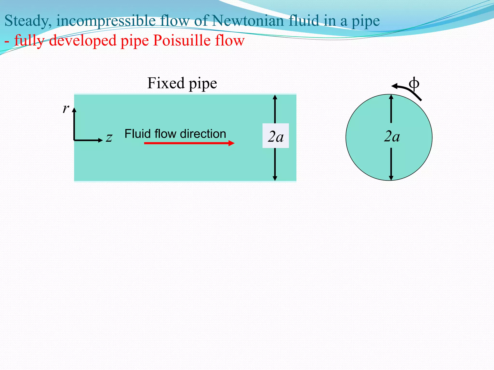
Steady, incompressible flowof Newtonian fluid in a pipe
- fully developed pipe Poisuille flow
Fixed pipe
z
r
Fluid flow direction 2a 2a
φ
29.
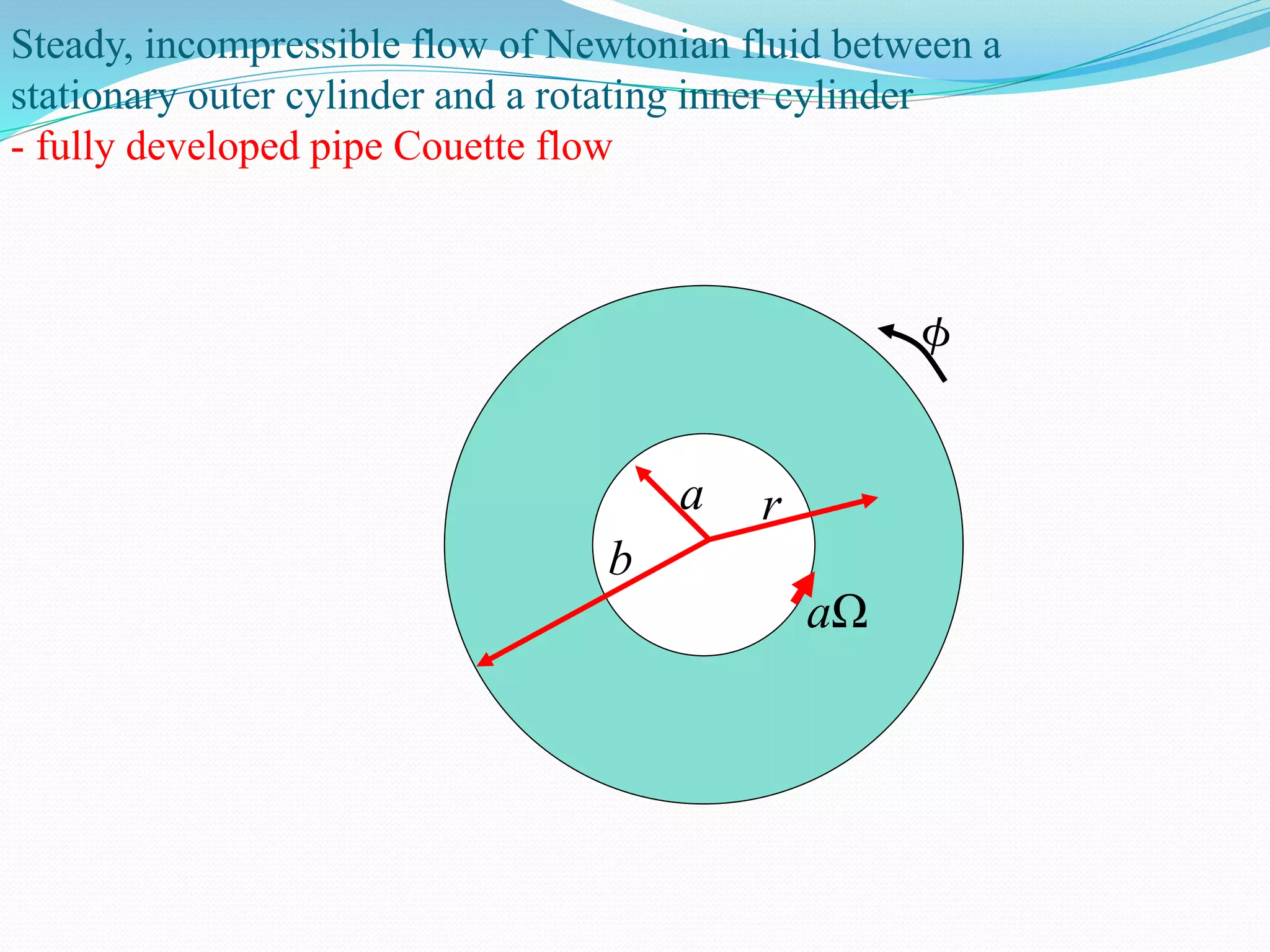
Steady, incompressible flowof Newtonian fluid between a
stationary outer cylinder and a rotating inner cylinder
- fully developed pipe Couette flow
aΩ
a
b
r
30.
13
developed laminar flow.
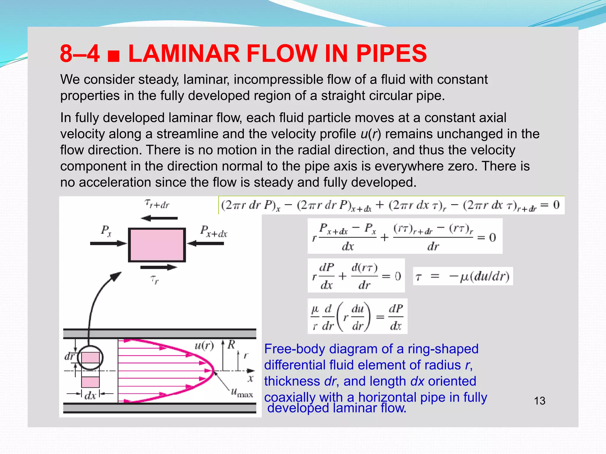
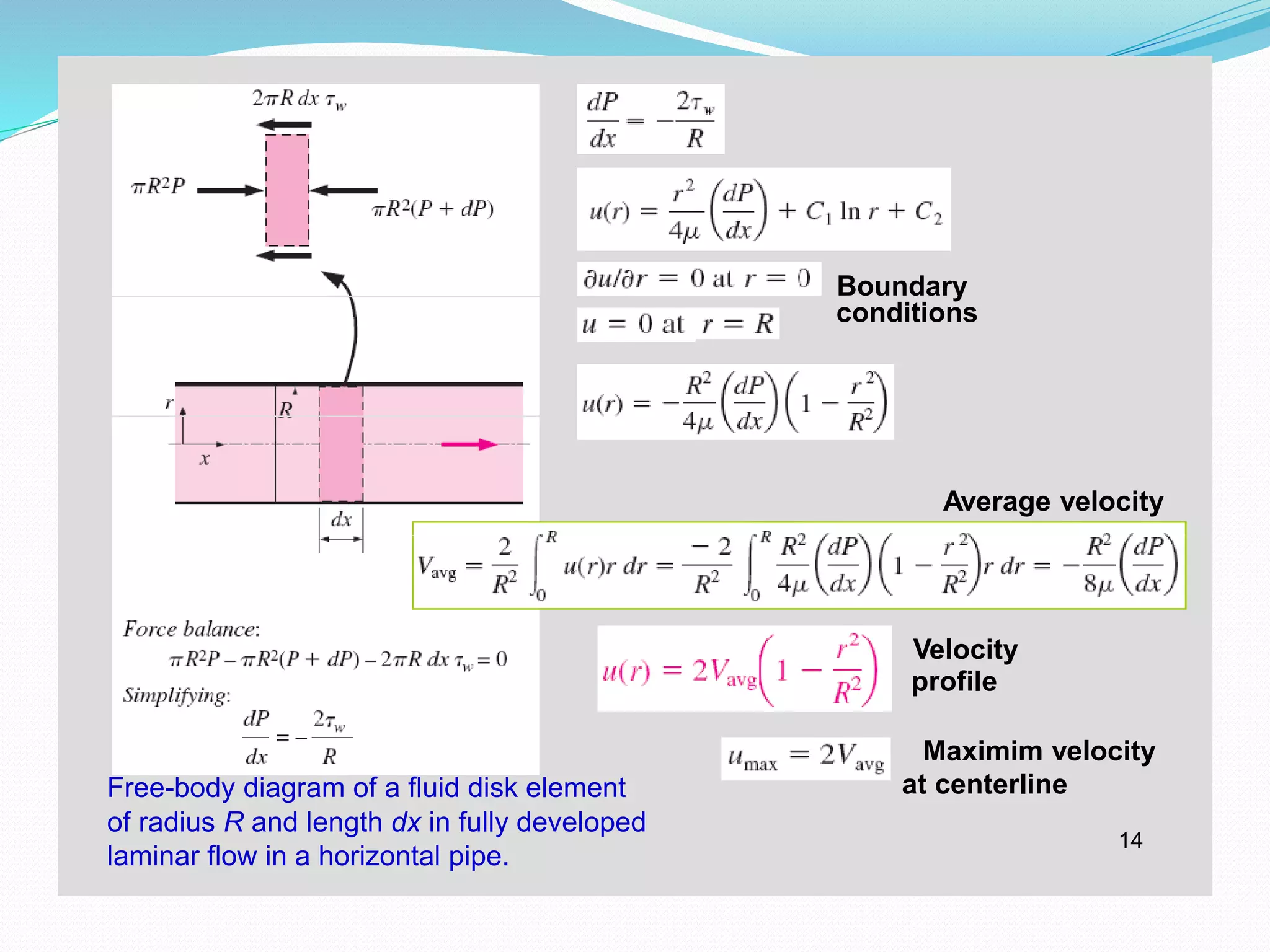
8–4■ LAMINAR FLOW IN PIPES
We consider steady, laminar, incompressible flow of a fluid with constant
properties in the fully developed region of a straight circular pipe.
In fully developed laminar flow, each fluid particle moves at a constant axial
velocity along a streamline and the velocity profile u(r) remains unchanged in the
flow direction. There is no motion in the radial direction, and thus the velocity
component in the direction normal to the pipe axis is everywhere zero. There is
no acceleration since the flow is steady and fully developed.
Free-body diagram of a ring-shaped
differential fluid element of radius r,
thickness dr, and length dx oriented
coaxially with a horizontal pipe in fully
31.
t t li
14
Boundary
conditions
Averagevelocity
Velocity
profile
Maximim velocity
Free-body diagram of a fluid disk element at centerline
of radius R and length dx in fully developed
laminar flow in a horizontal pipe.
32.
l
only and isindependent of the roughness of the pipe
types of fully developed
laminar
frictionpressure loss
15
raised by a pump in order to overcome the frictional losses in the pipe.
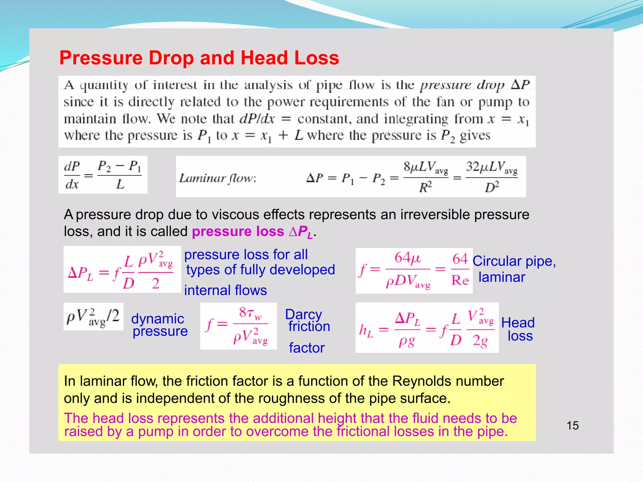
Pressure Drop and Head Loss
A pressure drop due to viscous effects represents an irreversible pressure
loss, and it is called pressure loss ∆PL.
pressure loss for all Circular pipe,
internal flows
dynamic Darcy
Head
factor
In laminar flow, the friction factor is a function of the Reynolds number
only and is independent of the roughness of the pipe surface.
The head loss represents the additional height that the fluid needs to be
33.
Horizontal
pipe
Poiseuille’s
law
The pumping powerrequirement for a laminarcircular or noncircular pipes, and
of 16 by doubling the pipe diameter.
For a specified flow rate, the pressure drop and
thus the required pumping power is proportional
to the length of the pipe and the viscosity of the
fluid, but it is inversely proportional to the fourth
power of the diameter of the pipe.
The relation for pressure loss (and
head loss) is one of the most general
relations in fluid mechanics, and it is
valid for laminar or turbulent flows,
pipes with smooth or rough surfaces. flow piping system can be reduced by a f1a6ctor
34.
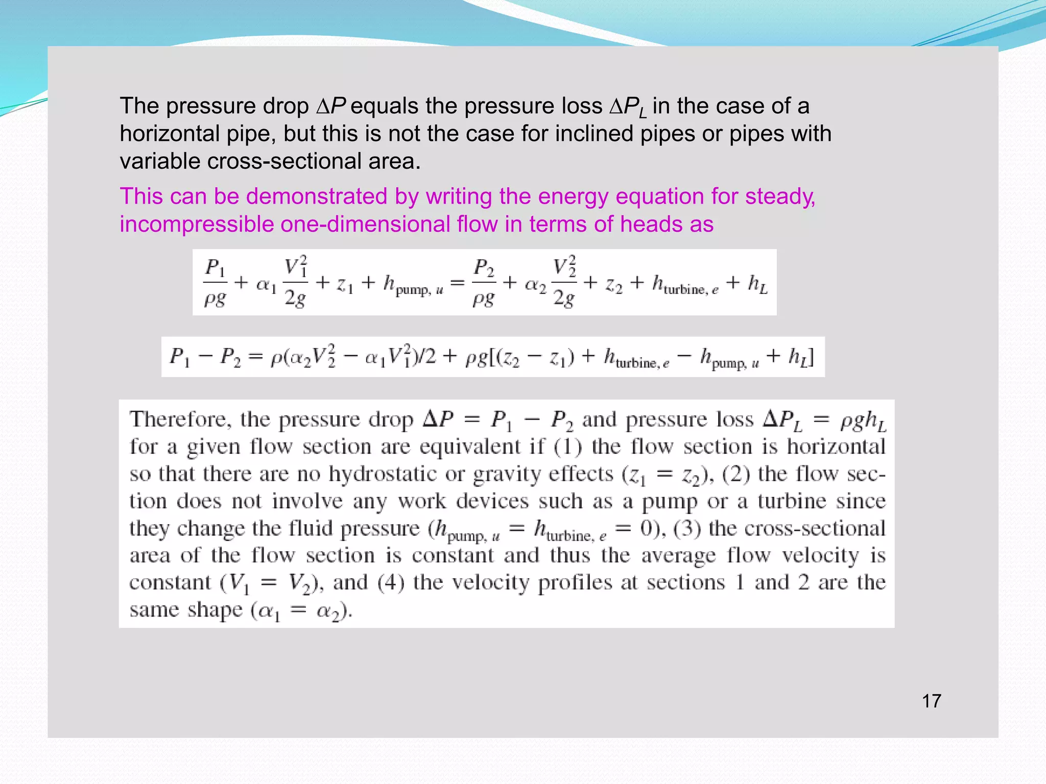
The pressure drop∆P equals the pressure loss ∆PL in the case of a
horizontal pipe, but this is not the case for inclined pipes or pipes with
variable cross-sectional area.
This can be demonstrated by writing the energy equation for steady,
incompressible one-dimensional flow in terms of heads as
17


![Vibe Coding vs. Spec-Driven Development [Free Meetup]](https://cdn.slidesharecdn.com/ss_thumbnails/vibecodingvsspecdrivendevelopment-251209105622-43f455e7-thumbnail.jpg?width=640&height=640&fit=bounds)

