Downloaded 936 times
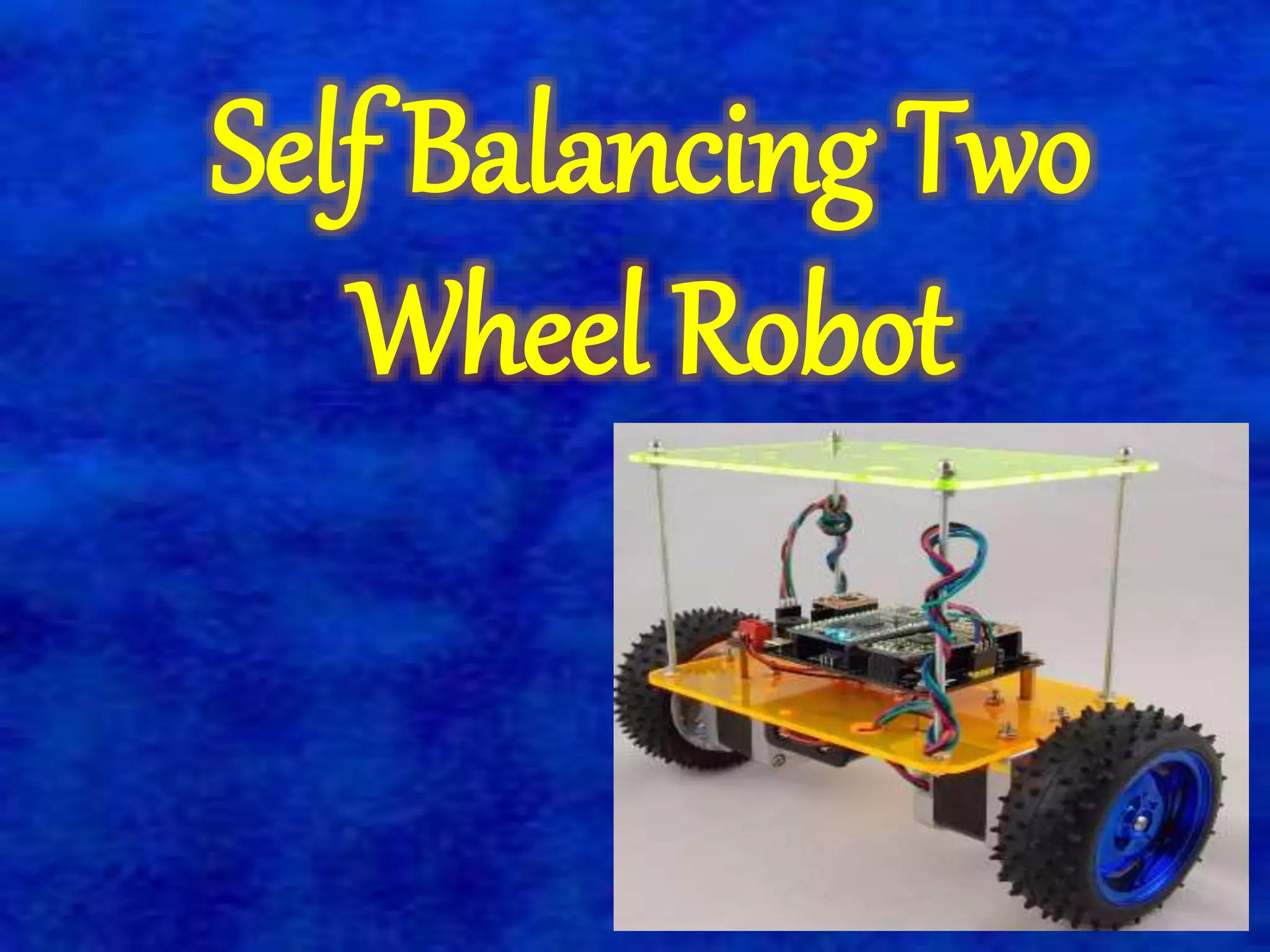
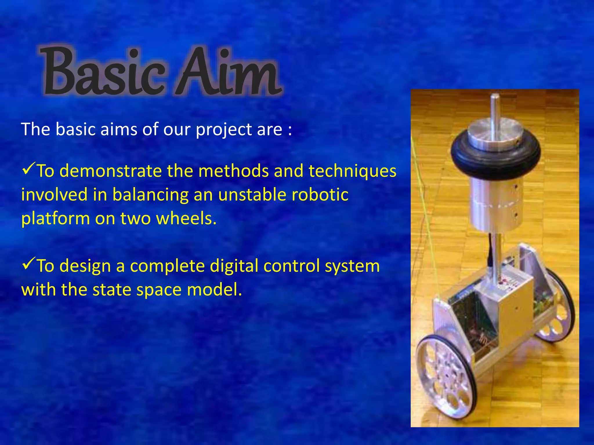
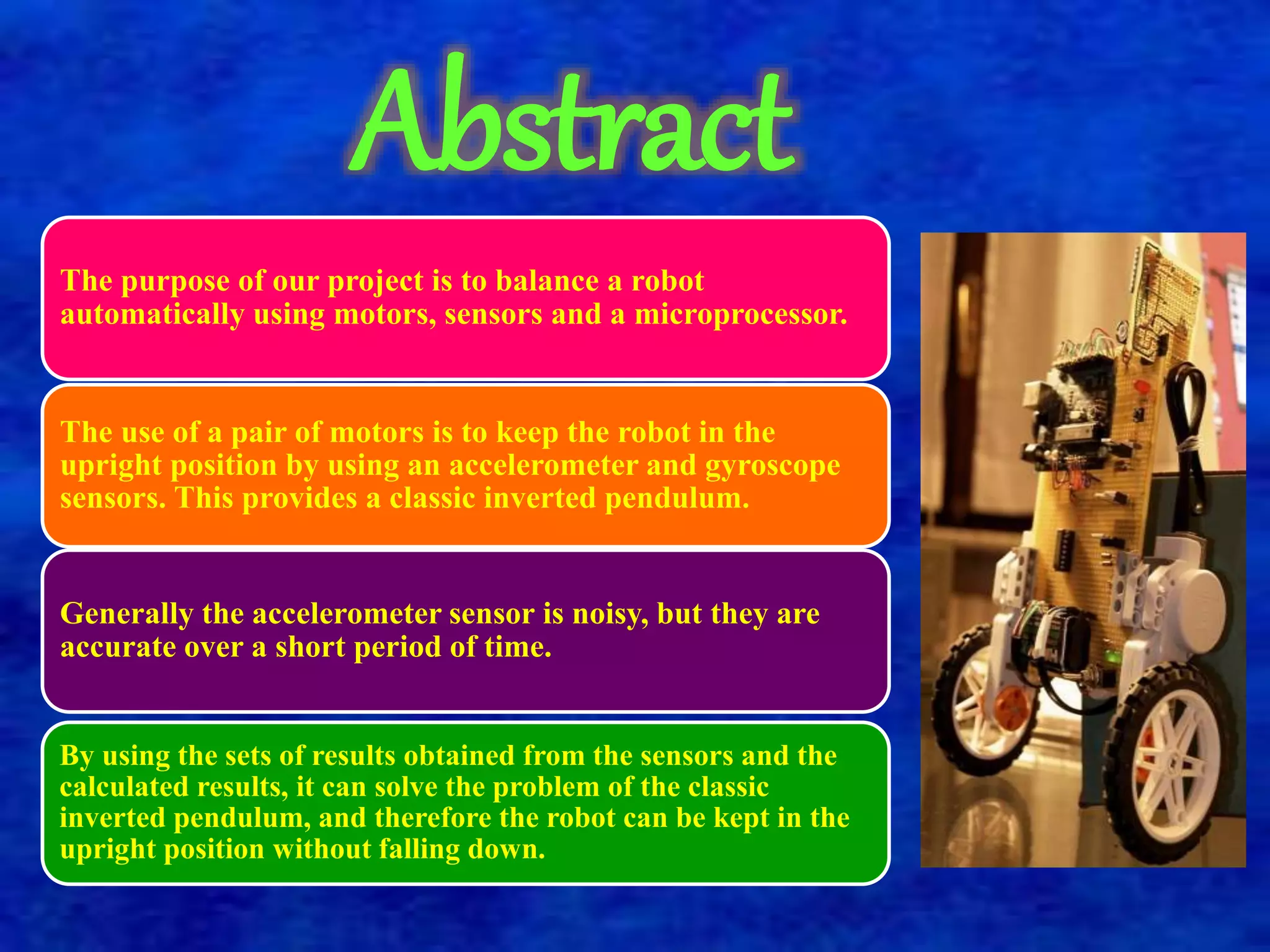

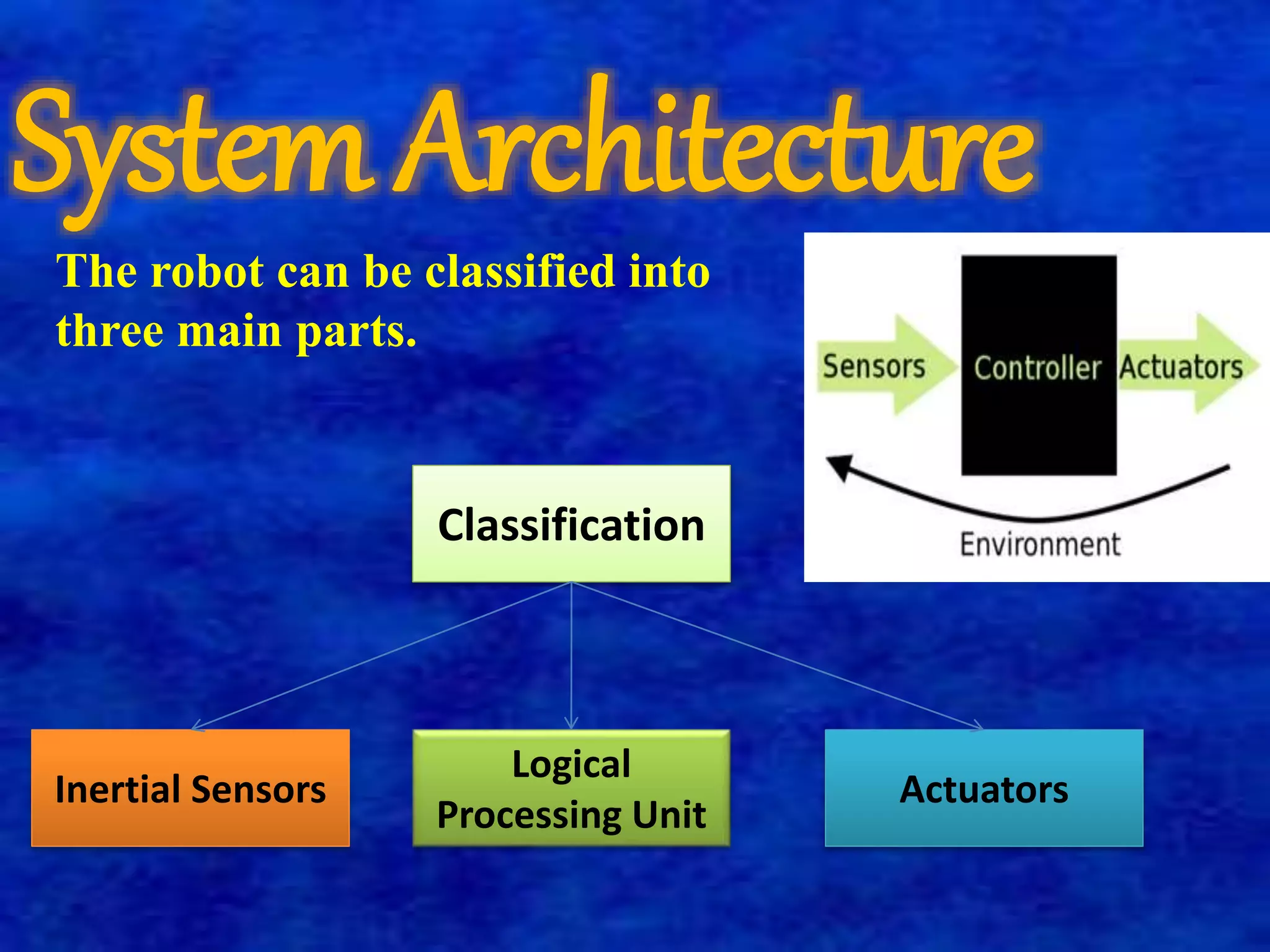
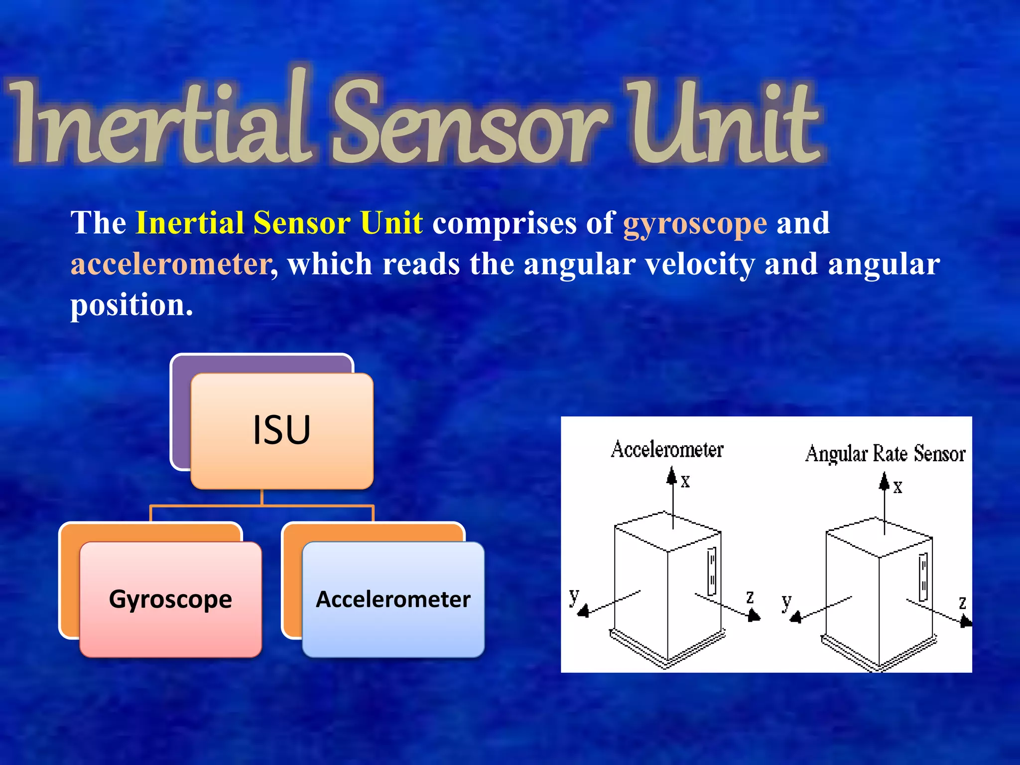
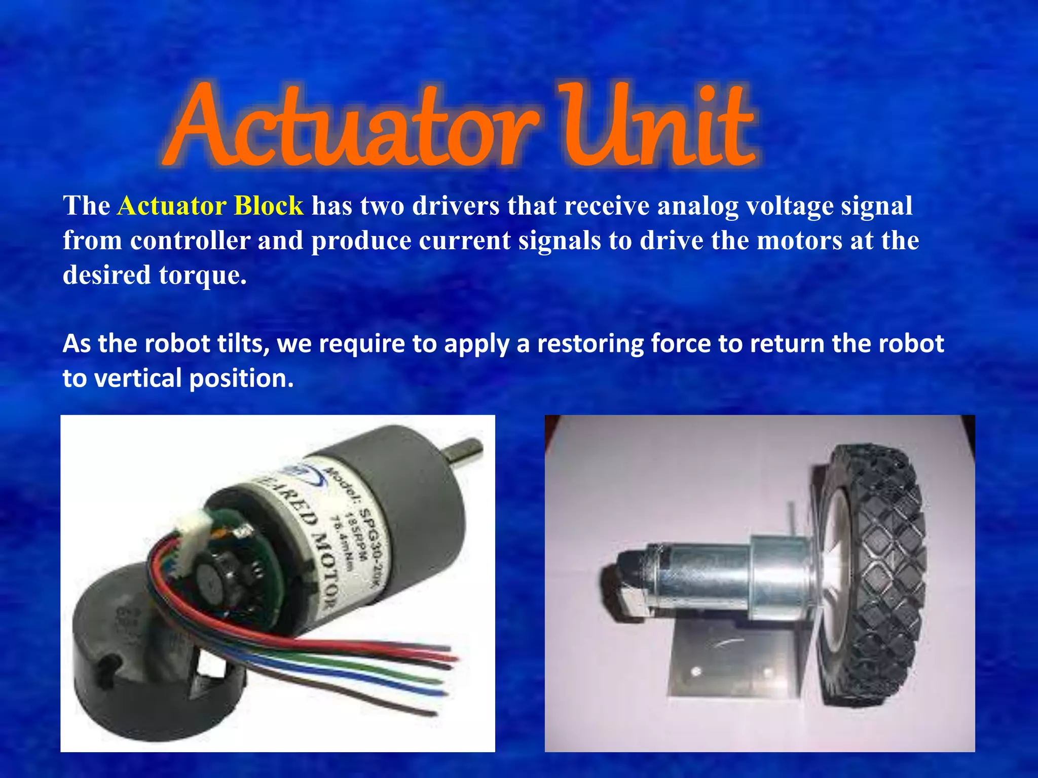
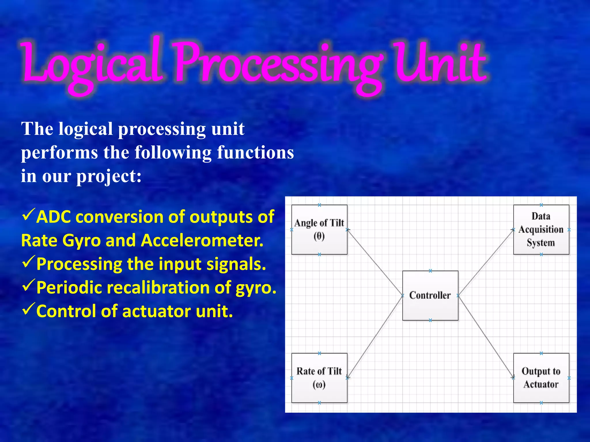
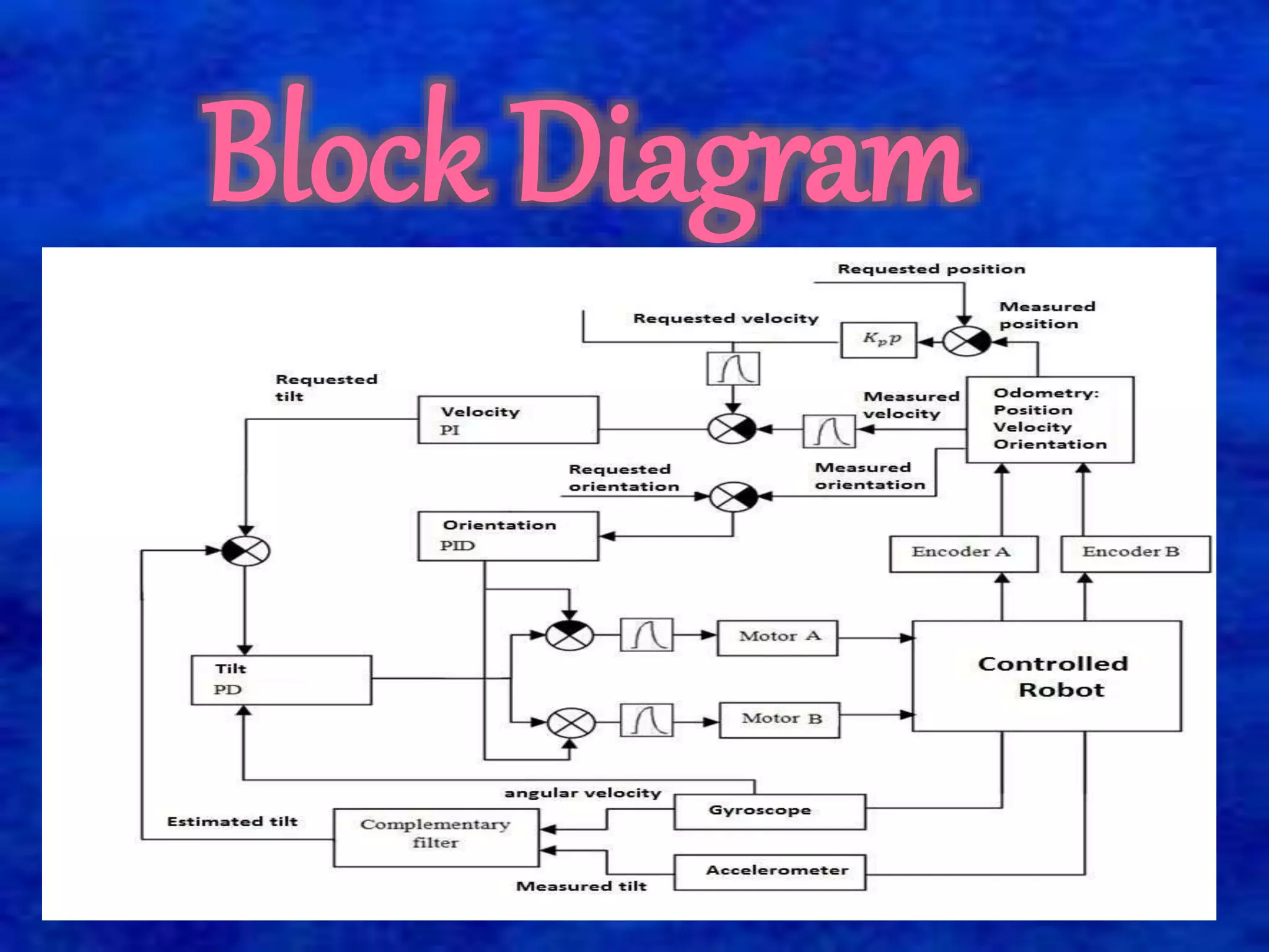


The document describes a self-balancing two-wheeled robot project. The goals of the project are to demonstrate techniques for balancing an unstable robotic platform on two wheels and to design a digital control system using a state space model. The robot uses motors, sensors like an accelerometer and gyroscope, and a microprocessor to automatically balance itself in the upright position like an inverted pendulum. It classifies the robot system into three main parts: an inertial sensor unit to read angular velocity and position, an actuator unit with motors driven by analog signals from the controller, and a logical processing unit that processes sensor inputs and controls the actuators to return the robot to vertical position when tilted.