The document discusses the stabilization control of a two-wheeled Segway robot, focusing on balance control using algorithms like Kalman filtering combined with pole placement and linear quadratic regulator methods. It emphasizes the importance of stability for such self-balancing robots and describes the mathematical modeling and simulations conducted using MATLAB Simulink. The results indicate that the proposed control method effectively maintains balance and responds accurately to disturbances, showcasing the implementation's potential for real-time applications.
![Bulletin of Electrical Engineering and Informatics
Vol. 9, No. 4, August 2020, pp. 1357~1363
ISSN: 2302-9285, DOI: 10.11591/eei.v9i4.1965 1357
Journal homepage: http://beei.org
Stabilized controller of a two wheels robot
Ahmad Fahmi1
, Marizan Sulaiman2
, Indrazno Siradjuddin3
, I Made Wirawan4
,
Abdul Syukor Mohamad Jaya5
, Mahfud Jiono6
, Zakiyah Amalia7
1,2
Faculty of Electrical Engineering, Universiti Teknikal Malaysia Melaka, Hang Tuah Jaya,
76100 Durian Tunggal, Melaka Malaysia
3,7
Department of Electrical Engineering, Politeknik Negeri Malang, Malang, Indonesia
1,4,6
Department of Electrical Engineering, Universitas Negeri Malang, Malang, Indonesia
5
Faculty of Information and Communication Technology, Universiti Teknikal Malaysia Melaka, Hang Tuah Jaya,
76100 Durian Tunggal, Melaka Malaysia
Article Info ABSTRACT
Article history:
Received Aug 27, 2019
Revised Oct 14, 2019
Accepted Dec 10, 2019
The Segway Human Transport (HT) robot, it is dynamical self-balancing
robot type. The stability control is an important thing for the Segway robot.
It is an indisputable fact that Segway robot is a natural instability framework
robot. The case study of the Segway robot focuses on running balance
control systems. The roll, pitch, and yaw balance of this robot are obtained
by estimating the Kalman Filter with a combination of the pole placement
and the Linear Quadratic Regulator (LQR) control method. In our system
configuration, the mathematical model of the robot will be proved by Matlab
Simulink by modelling of the stabilizing control system of all state variable
input. Furthermore, the implementation of this system modelled to
the real-time test of the Segway robot. The expected result is by substitute
the known parameters from Gyro, Accelero and both rotary encoder to initial
stabilize control function, the system will respond to the zero input curve.
The coordinate units of displacement response and inclination response
pictures are the same. As our expected, the response of the system can reach
the zero point position.
Keywords:
Inverted pendulum
Segway
Stabilize control
State-feedback
Two wheels robot
This is an open access article under the CC BY-SA license.
Corresponding Author:
Zakiyah Amalia,
Department of Electrical Engineering,
Politeknik Negeri Malang,
Soekarno Hatta 9, Malang, East Java 65141, Indonesia.
Email: zakiyah_amalia@polinema.ac.id
1. INTRODUCTION
A demand to increase the abilities of a user-friendly robot system has increased to overcome
difficulties of controlling robots especially for interaction between human beings and personal care robots.
One example of the personal care robot is Segway Human Transport (HT), it is dynamical self-balancing
robot type. Segway platforms are implementing human/robot coordination in the unknown environment
through the floor, road, field, etc. Full review in recent years, relating to control variables, control algorithm
and some application of the Segway. Segway has three states of control; without input coupling, reaction wheel,
and input coupling. In our research, we selected an element of the state control without input coupling.
In this state control, some control methods are already implemented such as PID [1] to advanced
methods of the sliding mode control, adaptive control [2, 3], neural network [4, 5], robust control [6],
back-stepping, LQR [7], observer [8, 9], pole placement [10] hybrid control [11], and fuzzy inference system
based control [12, 13]. There still have an unsolved challenging control problem between the control variable](https://image.slidesharecdn.com/6-1965-210802012954/75/Stabilized-controller-of-a-two-wheels-robot-1-2048.jpg)
![ ISSN: 2302-9285
Bulletin of Electr Eng & Inf, Vol. 9, No. 4, August 2020 : 1357 – 1363
1358
(pendulum) and reaction wheel [14-16]. So that effective control needs to be applied so that the system
makes it stable during work [17-19]. In this research, system configuration and Segway mathematical models
are explained using Matlab Simulink.
Among this system configuration, operating the Segway using differences between the angle
of the initial position and last angle of the pendulum, and the stability of system have wheels factors (actuator
specification and wheels diameter) [20]. The problems are considered as unknown disturbance
and the operator condition has to keep balancing on it in the first type of task. On the contrary, the active
movement of the operator is utilized as an interface to intuitively drive the Segway in the second type
of task [21-22]. Based on this problem, we use stabilize algorithm to minimize errors from some variables
above and improve the performance of the Segway. The motivation and challenge for my research
are optimism of continuing increases in effectiveness and reliability of controlling the Segway robot by using
our control stabilize method.
To support this, researchers have developed various control methods have been proposed from
the classic PID method to sophisticated methods such as sliding mode control, adaptive control, strong
control, back-stepping, and fuzzy inference-based control systems. There is already an important application
of the two-wheeled mobile robot (TWMR), for example, Segway, TWMR based cars and E-scooter.
Some system also uses the global position to support regulating the angular momentum around it
are considered as primary objectives, stabilizing the posture to make the Segway working smoothly [23].
Based on several types of research above, it is possible to develop new stabilize control method
of the Segway, by proving system stability can be controlled and the system is also anti-external interference.
If there is interference given to the system, the system will remain stable if the angle of interference provided
is still within limits., these our purpose of this experimental design of the Segway robot the system regulate
set to the zero point position. Next section will explain about the related work about the Segway robot.
2. RELATED WORKS
The Segway robot system has been conducted involving human-robot support system [24], where
a pendulum system is the main input control of the robot. These Segway systems have three degrees
of freedom (DoF); the rotation of inverted pendulum, forward and backward movement of the chassis as well
as the rotational movement the chassis. The first model of the Segway has been developed, it has the inverted
pendulum system and the rotational movement [25]. By using two state feedback controller by pole
assignment method of this system, it makes the Segway stable and able to reduce force and angular
disturbance from the rotational movement of the inverted pendulum. Another researcher also develops
the new version of the Segway with input coupling systems [26]. The DC motor as an actuator is mounted on
the pendulum so that the torque from the motor is given directly to the system: on the pendulum and both wheels.
The segway robot model is similar to the previous model, but there are additional wheels in
the system to maintain the stability of the pendulum. The pendulum is kept stable in a vertical position with
a PID controller. In addition, the Fuzzy Mamdani model has also been used to control this system [27].
Adaptive control is carried out in [28] to make this two-wheeled robot reach the desired setpoint. The use
of state transformation with the Lyapunov approach in adaptive control is also often used [29]. Problems with
the control method to reach the setpoint in this system, namely the location and balance of this nonlinear
control, can also be solved by a combination of fuzzy logic control and sliding mode control.
Of the various methods that have been used to control the balance on a Segway, there are limitations
to factors such as control ability, segway with input coupling, uneven track surface, and many others.
Some system failure factors such as dead batteries and if one of the two actuators fails to work also have not
been taken into account for the safety of some segway models. The purpose of this work is to mathematically
model the segway system, design the appropriate control method for this system, and its application.
Our experimental design will explain in section three.
3. RESEARCH METHOD
3.1. Mathematical model
The Segway Robot consists of two wheels, which are controlled by a DC motor and an inverted
pendulum in the center of the chassis. It is given that when the robot moves, the chassis rotates passively
around the axis of the wheels. The pendulum also rotates passively in the center of the chassis that places
between two wheels. One variable as state input control task of the robot is to maintain the position
of the pendulum around the vertical equilibrium point of the chassis. It means that the angle between
the pendulum and the vertical axis is mostly zero degrees even the operator was stand in the robot.
The second variable is the set point condition. Segway is expected to reach the desired position along](https://image.slidesharecdn.com/6-1965-210802012954/75/Stabilized-controller-of-a-two-wheels-robot-2-2048.jpg)
![Bulletin of Electr Eng & Inf ISSN: 2302-9285
Stabilized controller of a two wheels robot (Ahmad Fahmi)
1359
a straight line with any starting position. And the third variable is tracking control variable, it means that
the Segway robot keep movement to closely line the desired trajectory.
The movement of this robot has 3 directions, namely the movement of the robot on the X-axis,
the wheel shaft as the Y-axis, the pendulum is perpendicular to the Z-axis, and suppose that the robot's mass
is located or concentrated at point g. Figure 1 shows the segway model. Figure 1 shows a system that has 3
degrees of freedom (DOF), namely the movement on the X-axis (Roll) that moves on the X-axis with speed
V, the winding movement on the Y-axis (Pitch) with angle with angular velocity ω (mg), and rotary motion
on the Z (Yaw) axis with angle φ and angular velocity ω β. The x-axis, the velocity V, the angle, the angular
velocity ω, the angle φ, and the angular velocity β β are 6 space variable variables that describe the dynamic
characteristics of this system. It is assumed that the external disturbance that occurs in this system is located
at point g.
Figure 1. Model of segway
3.2. Experimental design
Products which are presented from the mathematic model is linearizing the nonlinear around
the vertical equilibrium point of the chassis.
The system can be written in the state-space form:
̇
Where, X denotes the state vector, u are input torques on the left and right wheel.
[ ]
[ ]
We assume that mass of the whole body and the motor as m notation, R is the radius of the wheels
and height of the pendulum above the wheel axel given by L as well as the gravity g. Then we can calculate
the moment inertia variable both the chassis body and total moment inertia effective. To calculate
the effective total moment of inertia (Jeff) = inertia of the chassis body + wheels inertia + pendulum inertia
Now the variable A and B given:
[ ]
[ ]](https://image.slidesharecdn.com/6-1965-210802012954/75/Stabilized-controller-of-a-two-wheels-robot-3-2048.jpg)
![ ISSN: 2302-9285
Bulletin of Electr Eng & Inf, Vol. 9, No. 4, August 2020 : 1357 – 1363
1360
By calculate form state-input variable, so the matrix A given:
[ ]
After calculating the motor DC velocity as state input, B given:
[ ]
Where Kdc is the gain of motor DC velocity. Then the stability control of the Segway.
[ ] [ ]
Where G is equal B that means process disturbance assumed to come in as an error in the motor drive and H
is the process disturbance does not directly affect outputs. If we implemented process noise (motor drive
error) given by QN and measurement noise from excel, then gyro then motor encoder, again this is expected
the value of noise squared given by RN. Then the stability control total by using the Kalman filter method is
Next section will explain about Matlab Simulink model of this mathematical equation.
3.3. Matlab simulink design
The two-wheeled inverted pendulum has been very often discussed by some literature as
an application of the control method. Common parameters to be controlled on a conventional pendulum are x
and θ. In this work, the control system that is controlled is yaw φ and speed ω. It is hoped that this system can
function as a safe human carrier by linearizing the mathematical model of the system. Even so, there
are some nonlinear terms that cannot be easy because the required assumptions are not fulfilled. Figure 2
shows the control design, where the controller is using the Kalman Filter with LQR and pole placement,
and the plant is a two-wheeled robot.
Figure 2. Control design
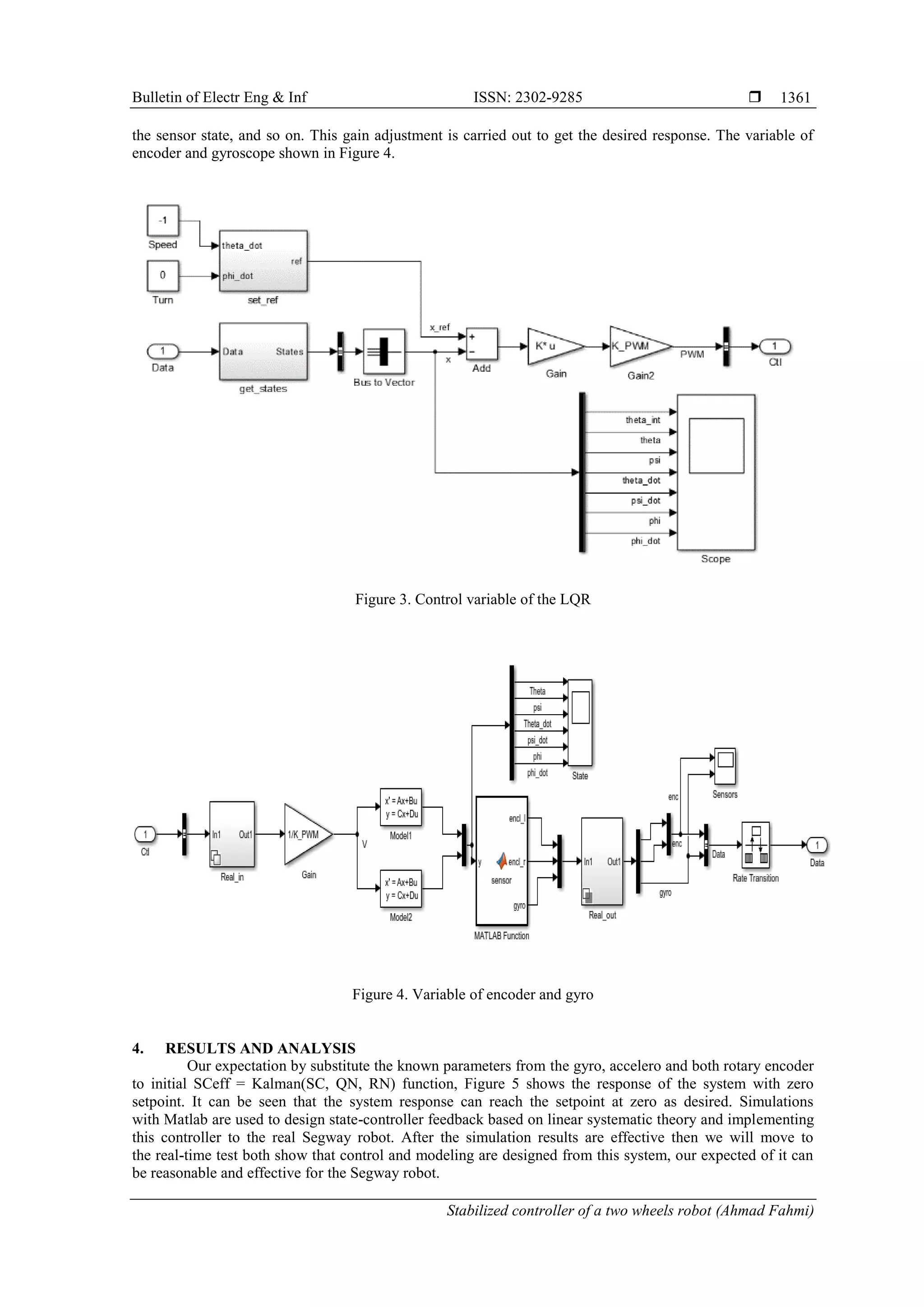
It is given that four state input variable of the system can be measured by Accelerometer, Gyroscope
and two rotary encoders from both left and right motors. This means that the Simulink design can be used as
an observer of full-dimensional state input variables. These four state variable will be processed by Kalman
state estimator to estimate the value X and Y. These Kalman state estimator matrices and full state feedback
gains as designed by LQR or pole placement as shown in Figure 3.
The results from the above simulations show that state feedback has gained, and the arithmetic
control program is written in another Matlab script. So that the testing of the prototype in real-time conditions
can be tested. The feedback gain on the state feedback control can be adjusted constantly. This gain
adjustment is adjusted for errors in modeling and the realtime state, the death district in the DC motor,](https://image.slidesharecdn.com/6-1965-210802012954/75/Stabilized-controller-of-a-two-wheels-robot-4-2048.jpg)
![ ISSN: 2302-9285
Bulletin of Electr Eng & Inf, Vol. 9, No. 4, August 2020 : 1357 – 1363
1362
Figure 5. Real-time result
5. CONCLUSION
The control system for a two-wheeled robot balance has been successfully applied in this paper.
The proposed optimal controller for the non-linear system of the two wheels robot obtains the response with
a great performance. The controller makes the balance between speed response and control angle position
condition as well. The faster response achieved in unstable condition between speed and angle of the two
wheels robot. For this condition, Kalman filter and 7-stages control system adjusted. To analyze the effects
of interference, the result in Figure. 5 between displacement response and an inclination response system
response curves of Zero Input that indicates the rejection of disturbance applied at with optimal controller.
ACKNOWLEDGEMENTS
This work was supported by PNBP research grant of Universitas Negeri Malang Under Contract
No: 20.3.175/UN 32.14.1/LT/2019
REFERENCES
[1] Siradjuddin, Indrazno, et al., “Stabilising a cart inverted pendulum with an augmented PID control scheme,”
MATEC Web of Conferences, EDP Sciences, vol. 197, pp. 11013, 2018.
[2] Ge, S.S., Yang, C., and Lee, T.H., “Adaptive predictive control using neural network for a class of pure-feedback
systems in discrete-time,” IEEE Trans. Neural Netw, vol. 19, no. 9, pp. 1599-1614, 2008.
[3] Han, H., Su, C., and Stepanenko, Y. “Adaptive control of a class of nonlinear systems with nonlinearly
parameterized fuzzy approximators,” IEEE Trans. Fuzzy Syst, vol. 9, no. 2, pp. 315-323, 2001.
[4] Giles, C.L., and Maxwell, T. “Learning, invariance, and generalization in high-order neural networks,” Appl. Opt,
vol. 26, no. 23, pp. 4972-4978, 1987.
[5] Gupta, M.M., and Rao, D.H. “Neuro-control Systems. Theory and Applications,” IEEE Press, 1994.
[6] Gruszka, A., Malisoff, M., and Mazenc, F. “Tracking control and robustness analysis for planar vertical takeoff and
landing aircraft under bounded feedbacks,” Int. J. Robust Nonlinear Control, vol. 22, no. 17, pp. 1899-1920, 2011.
[7] I. Siradjuddin, et al., “State space control using lqr method for a cart-inverted pendulum linearised model,” International
Journal of Mechanical and Mechatronics Engineering IJMMEIJENS, vol. 17, no. 01, pp. 119-126, 2017.
[8] Ibanez, C.A., Frias, O.G., and Castanon, M.S., “Lyapunov-based controller for the inverted pendulum cart system,”
Nonlinear Dyn, vol. 40, no. 4, pp. 367-374, 2005.
[9] Siradjuddin, Indrazno, et al. “State-feedback control with a full-state estimator for a cart-inverted pendulum
system,” International Journal of Engineering & Technology, vol. 7, no. 4.44, pp. 203-209, 2018.
[10] Siradjuddin, Indrazno, et al. “Stabilising a cart inverted pendulum system using pole placement control method,”
2017 15th International Conference on Quality in Research (QiR): International Symposium on Electrical and
Computer Engineering, IEEE, pp. 197-203, 2017.
[11] Zhang, M., and Tarn, T.,” Hybrid control of the Pendubot,” IEEE/ASME Trans. Mechatron. vol. 7, no. 1, pp. 79-86, 2002.
[12] Tran, K.G., Nguyen, P.D. and Nguyen, N.H. “Advanced control methods for two-wheeled mobile robots,” In
System Science and Engineering (ICSSE), 2017 International Conference on IEEE, pp. 344-348, 2017.
[13] Muhammad, Mustapha, et al., “Velocity control of a two-wheeled inverted pendulum mobile robot: a fuzzy model-
based approach,” Bulletin of Electrical Engineering and Informatics, vol. 8, no. 3, pp. 808-817, 2019.
[14] Grasser, F., et al., “JOE: a mobile, inverted pendulum,” IEEE Trans. Ind. Electron, vol. 49, no. 1, pp. 107-114, 2002.
[15] Ha, Y.S., and Yuta, S., “Trajectory tracking control for navigation of the inverse pendulum type self-contained
mobile robot,” Robot. Auton. Syst, vol. 17, no. 1-2, pp.65-80, 1996.](https://image.slidesharecdn.com/6-1965-210802012954/75/Stabilized-controller-of-a-two-wheels-robot-6-2048.jpg)
![Bulletin of Electr Eng & Inf ISSN: 2302-9285
Stabilized controller of a two wheels robot (Ahmad Fahmi)
1363
[16] Brooks, R., Aryananda, L., et al., “Sensing and manipulating built-for-human environments,” Int. J. Humanoid
Robot, vol. 1, no. 1, pp. 1-28, 2004.
[17] Ge, S.S., Ren, B., Tee, K. P., Lee, T. H., “Approximation based control of uncertain helicopter dynamics,” IET
Control Theory Appl, vol. 3, no. 7, pp. 941-956, 2004.
[18] Gracanin, D., et al., “Virtual-environmentbased navigation and control of underwater vehicles,” IEEE Robot.
Autom. Mag, vol. 6, no. 2, pp. 53-63, 1999.
[19] Pathak, K., Franch, J., and Agrawal, S.K. “Velocity and position control of a wheeled inverted pendulum by partial
feedback linearization,” IEEE Trans. Robot, vol. 21, no. 3, pp. 505-513, 2005.
[20] Hahn, W., “Stability of Motion,” Berlin: Springer, vol. 138, 1967.
[21] Gans, N.R., and Hutchinson, S.A., “Visual servo velocity and pose control of a wheeled inverted pendulum through
partial-feedback linearization,” In: Proc. IEEE/RSJ Int. Conf. Intelligent Robots and Systems, pp. 3823-3828, 2006.
[22] Adinandra, Sisdarmanto, and Dwi Ana Ratnawati, “A practical coordinated trajectory tracking for a group of mixed
wheeled mobile robots with communication delays,” TELKOMNIKA Telecommunication, Computing, Electronics
and Control, vol. 14, no. 4, pp. 1397-1407, 2016.
[23] Igarashi H, et al., “Development of an autonomous inverted pendulum mobile robot for outdoor environment,”
InSICE Annual Conference, IEEE, pp. 2282-2285, 2008.
[24] Searock J, Browning B, and Veloso M., “Turning segways into soccer robots,” In Intelligent Robots and Systems,
(IROS 2004). Proceedings. 2004 IEEE/RSJ International Conference, IEEE, vol. 1, pp. 1029-1034, 2004.
[25] Rudra S, Barai RK, and Maitra M., “Block Backstepping Design of Nonlinear State Feedback Control Law for
Underactuated Mechanical Systems,” Springer, 2017.
[26] Chiu CH, and Chang CC., “Design and development of Mamdani-like fuzzy control algorithm for a wheeled human-
conveyance vehicle control,” IEEE Transactions on industrial electronics, vol. 59, no. 12, pp. 4774-83, 2012.
[27] Huang CH, Wang WJ, and Chiu CH., “Design and implementation of fuzzy control on a two-wheel inverted
pendulum.” IEEE Transactions on Industrial Electronics, vol. 58, no. 7, pp. 2988-3001, 2011.
[28] Kim HW, and Jung S., “Control of a two-wheel robotic vehicle for personal transportation,” Robotica, vol. 34,
no. 5, pp. 1186-208, 2016.
[29] Tran KG, Nguyen PD, and Nguyen NH., “Advanced control methods for two-wheeled mobile robots,” In System
Science and Engineering (ICSSE), 2017 International Conference, IEEE, pp. 344-348, 2017.](https://image.slidesharecdn.com/6-1965-210802012954/75/Stabilized-controller-of-a-two-wheels-robot-7-2048.jpg)