Downloaded 1,342 times
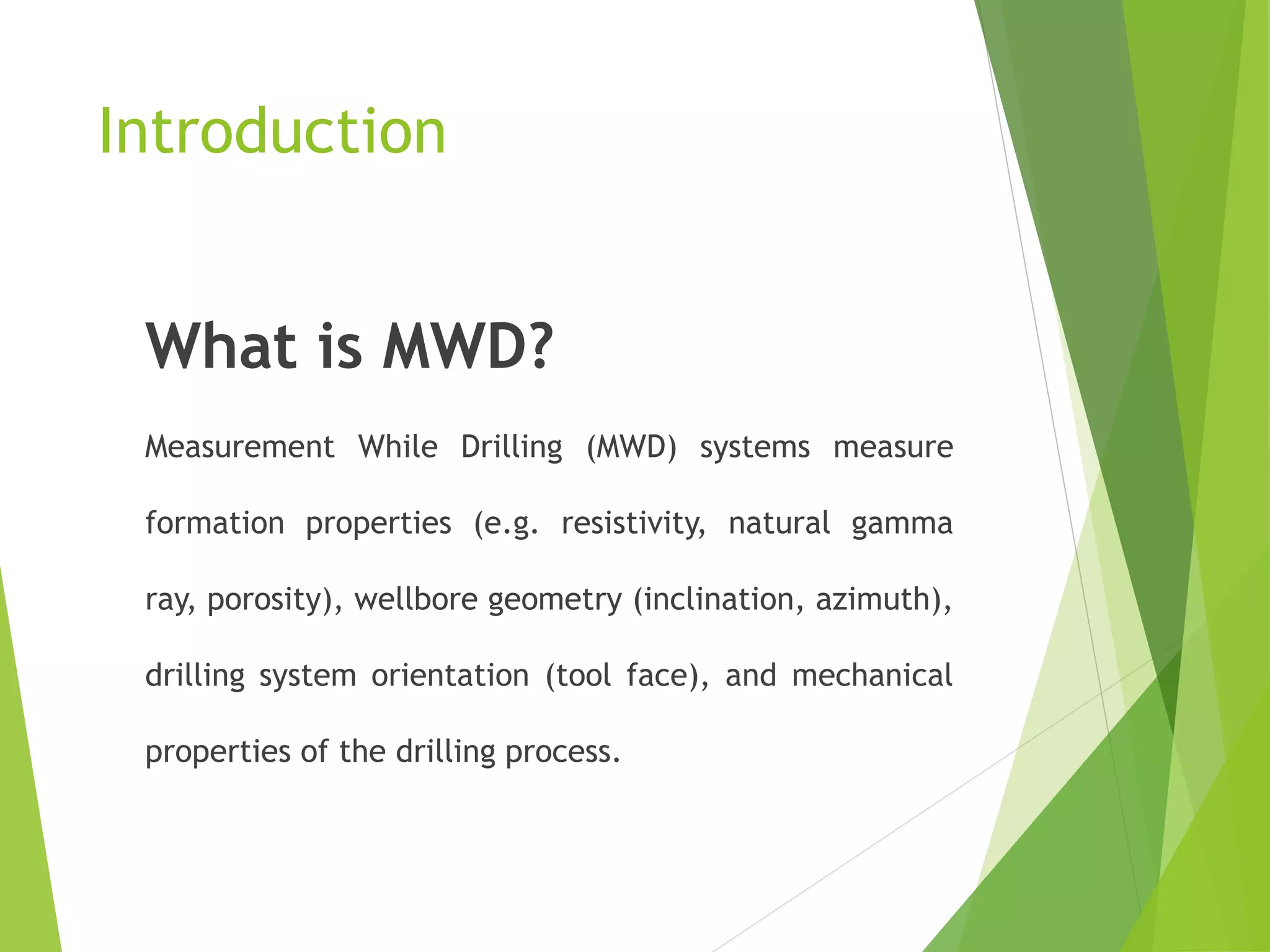
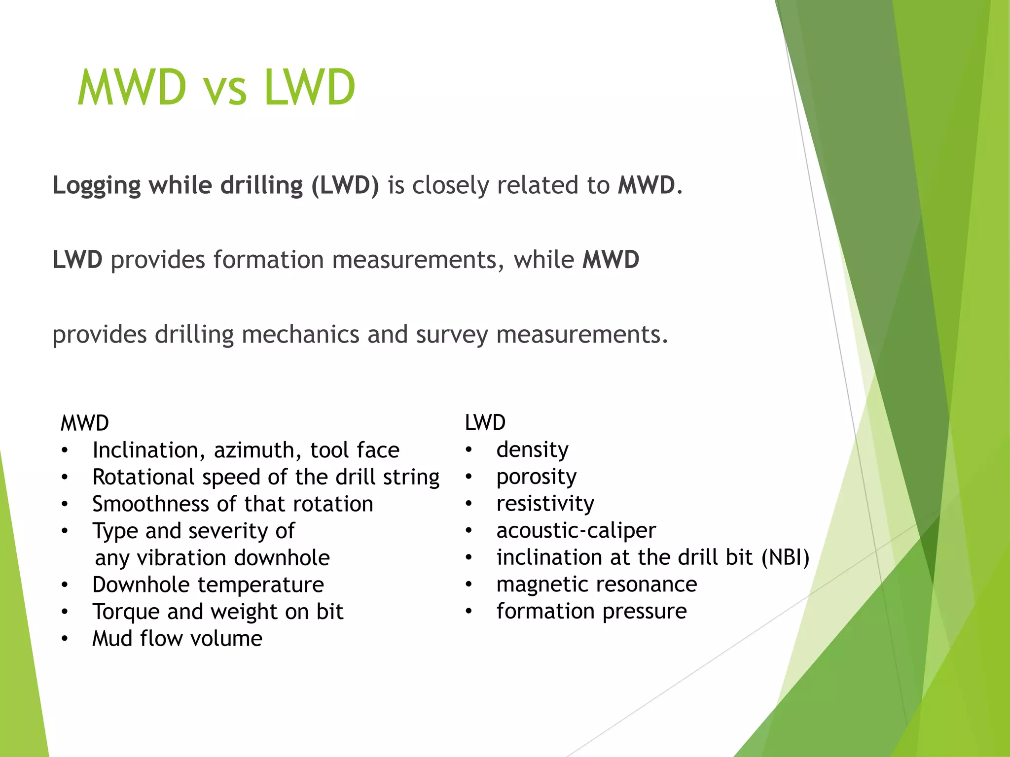
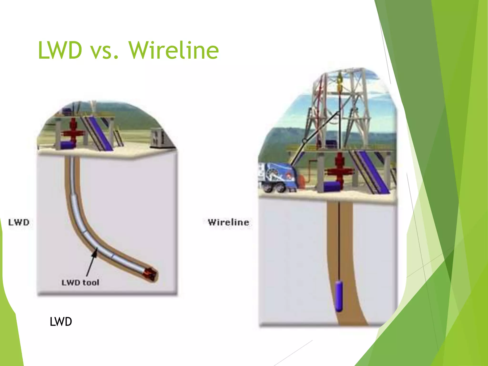
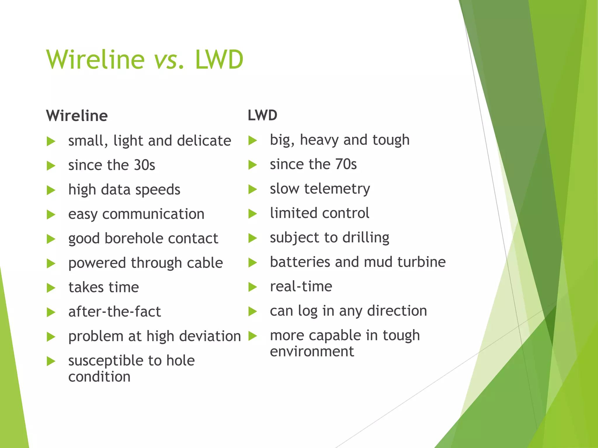

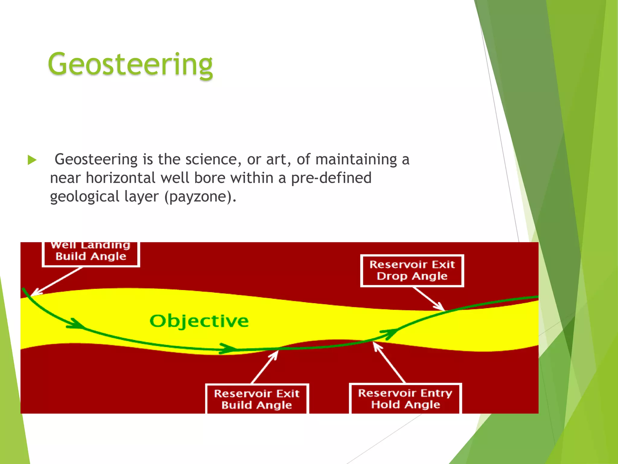
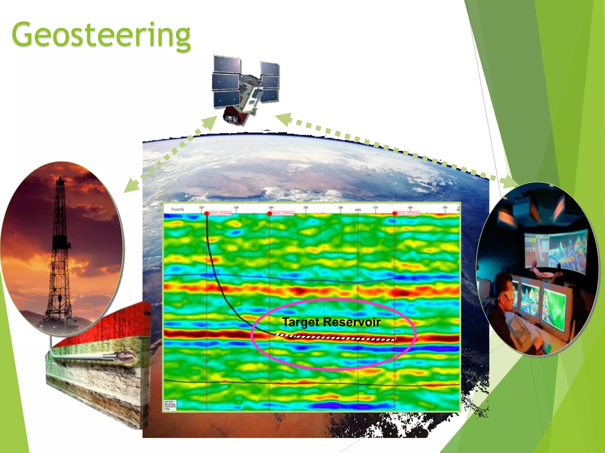

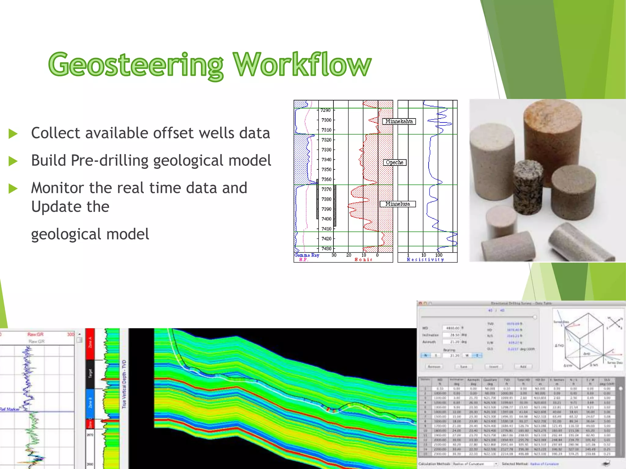

The document discusses Measurement While Drilling (MWD) and its relation to Logging While Drilling (LWD) and wireline technologies, detailing their functionalities, applications, and comparison in terms of data transmission methods and tools. It highlights the significance of geosteering for optimizing well placement and maximizing reservoir exposure, along with the advancements in MWD/LWD technology. Furthermore, it provides insights into telemetry methods and the evolution of drilling technologies for improving drilling efficiency.