Download to read offline


![Baker Hughes Incorporated Advancing Reservoir Performance
©2009 Baker Hughes Incorporated. All Rights Reserved. COR-09-25419.
Prolonglifeability
[pruh-lawng-lahyf-uh-bil-i-tee]
n. Skill or ability of Baker Hughes to extend ESP run life.
Baker Hughes delivers unmatched design, support and service to help you meet
your production performance objectives. And with the widest range of ESP
experience, technology and expertise, Baker Hughes can tailor solutions to meet
your financial objectives as well.
Our fit-for-purpose ESP technology is designed to deliver engineered expertise
that optimizes production at the lowest possible lifting costs.
Contact Baker Hughes today to learn how Centrilift Prolonglifeability can
advance the performance of your reservoir.
www.bakerhughes.com/centrilift
CEN-09-25457-Saudia.Arabia.O&G-Ad-rev.indd 1 4/17/2009 3:55:35 PM](https://image.slidesharecdn.com/cfa76e45-08f3-4dee-aba3-0f48427aa567-161219084258/85/saudi_arabia_baixa-7-320.jpg)


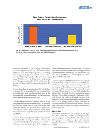
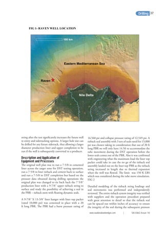
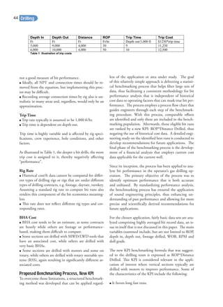
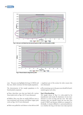
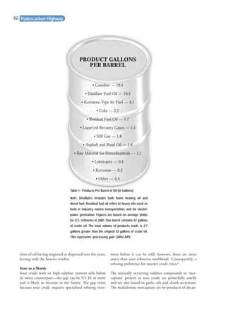
![the planned well path. This technique allowed drilling
crews to maintain a very high ROP performance while
staying on target with minimal input. This process took
some time to master, and not every crew was confident
enough to employ it; sometimes the reservoir sections
did not have hard streaks close enough to the planned
TVD to allow for this type of “geo-turning”. This use of
“geoturning” played a significant part in achieving the
very high ROP results in the latter part of the subject
field project.
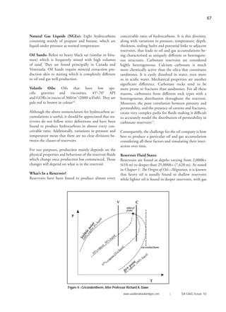
The implementation of such an application and the
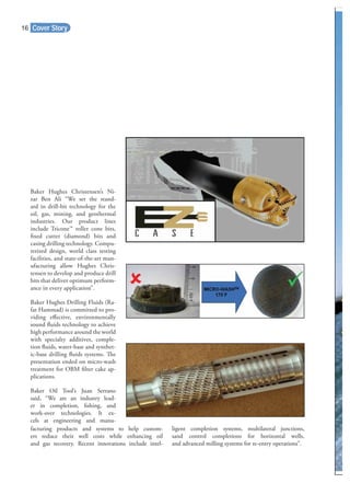
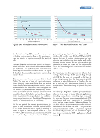
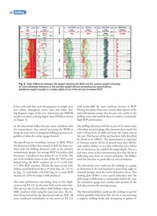
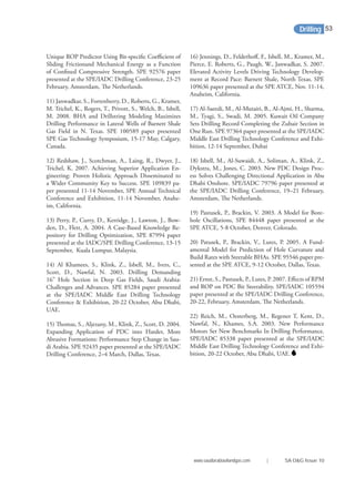
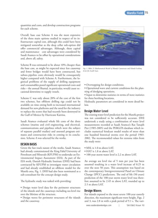
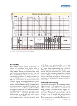
Fig. 6: Two charts with the near bit inclination plotted against the survey DLS (chart a) and
bending moment (chart b). Noticeably, these display a lot of deflections taking place in the
azimuthal plane that do not necessarily show up on the usual survey listing, but that are clearly
captured by the downhole bending moment measurement.
NBI vs Bending Moment
0
2000
4000
6000
8000
10000
12000
7900 8400 8900 9400 9900 10400 10900 11400 11900
Depth (ft)
BendingMoment(ft.lb)
85
86
87
88
89
90
91
92
93
94
95
NearBitInclination(deg)
DBMAM(ft-lb)
NBI
NBI vs Survey DLS
0
2
4
6
8
10
12
7900 8400 8900 9400 9900 10400 10900 11400 11900
Depth (ft)
DLS(deg/100ft)
85
86
87
88
89
90
91
92
93
94
95
NearBitInclination(deg)
Dogleg [deg/100ft]
NBI
Drilling30](https://image.slidesharecdn.com/cfa76e45-08f3-4dee-aba3-0f48427aa567-161219084258/85/saudi_arabia_baixa-30-320.jpg)


![Water is nearly always present in gas reservoirs and res-
ervoir gas is often substantially saturated with water va-
pour at the temperature at which it enters the wellbore.
With the change in temperature and pressure from the
subsurface to surface, the gas will not be able to hold
as much water and it will condense both within the
well during the upward travel of the gas and in surface
equipment. Much of this condensed water is carried
in the flow lines into the separator as entrained drop-
lets. Water can form hydrates with natural gas, which
can create production difficulties, rendering metres
and valves inoperative and, on occasions, causing disas-
ters. Low temperature separators are needed to remove
the entrained water close to the wellhead before the
gas arrives at trouble points. In many cases, appreci-
able amounts of water will settle to the bottom of the
well and can, in time, saturate the zone surrounding
the wellbore so that the permeability to the flow of gas
may be materially reduced. This reduction can result
either from water blocking or clay swelling and can be
responsible for a gradual decrease in deliverability and
periodic remedial work-overs10
.
Other impurities can be metallic such as vanadium or
non-metallic such as hydrogen sulphide (H2S). If there
is any measurable sulphur content (more than one part
per million), then the sulphur components, H2S, can
cause considerable damage to the production facilities
unless they are designed to handle sulphur. The sul-
phur components are also poisonous to humans hence
lowering the commercial value of the oil or gas. They
therefore have to be extracted, but can be converted
to sulphur and sold on as a useful product. The pro-
duction equipment has to use special quality steels to
prevent rapid corrosion. Getting rid of sulphur, water,
chlorides and other such impurities improves quality,
increases value and stretches the world’s oil reserves but
it also adds to cost11
.
Releasing Hydrocarbons
The production of underground hydrocarbons is
based on the release of trapped and pressurised fluids.
Production involves a reduction in pressure and tem-
perature from downhole reservoir conditions to atmos-
pheric or surface conditions. As a result, hydrocarbons
originally present as only liquid underground will sepa-
rate into liquid and gas on their way to the surface,
as soon as well pressure declines below the ‘bubble
point’.
In a mixture of liquids, the bubble point occurs when
the first bubble of vapour is formed. For single compo-
nent mixtures, the bubble point and dew point are the
same and are referred to as the boiling point.
Hydrocarbons originally present as gas underground
will generally produce some liquid at the surface due
to condensation, which occurs when the pressure and
temperature are reduced. The point at which natural
gas components start to condense out of the gaseous
system is known as the hydrocarbon dew-point and re-
fers to the temperature (at a stated pressure) at which
this occurs. Both bubble point and dewpoint are useful
data when designing distillation refinery systems.
Surface facilities will mechanically separate gas from
liquid using gravity separators or de-gassing facilities
after which the volumes of liquid and gas are measured
separately.
Gas
Natural gas volumes are reported in standard cubic me-
tres [(s)m3
] or standard cubic feet (scf). Quantities of
natural gas are usually expressed in cubic feet; a cubic
foot is equivalent to approximately 0.028 m3
at stand-
ard conditions12
. For reserves valuation, gas is usually
expressed in thousands (103
) of cubic feet (Mcf), mil-
lions (106
) of cubic feet (MMcf), billions (109
) of cubic
feet (BCF) or trillions (1012
) of cubic feet (TCF).
Methane is the most abundant component of natural
gas and has numerous fuel applications. These range
from liquefaction, compression, and Gas to Liquids
(GTL). For further details, see Chapter 13: Renewable
Hydrocarbon Highway
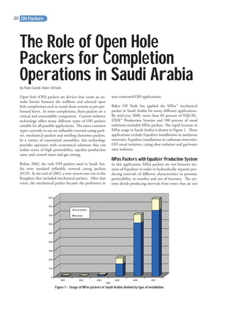
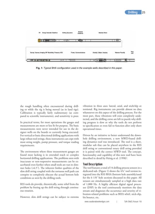
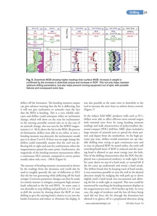
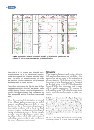
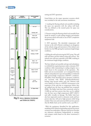
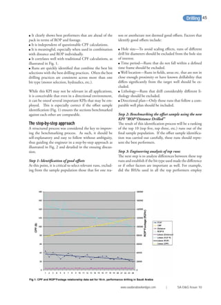
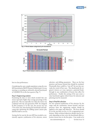
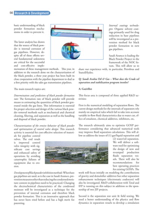
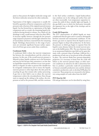
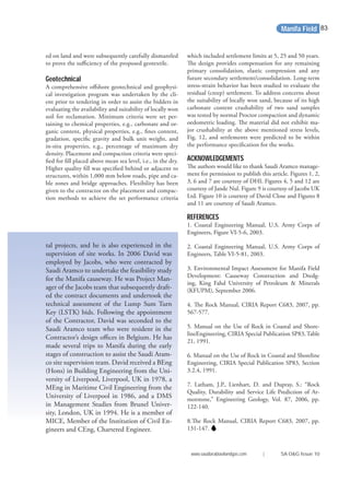
Table 4 - A Rough Classification of Crude Oil Is Sometimes Used Based on API Gravity
°API = (141.5°/SG - 131.5 [SG = specific gravity at 60°F = 1.0])
API Gravity
(°API)
Classification Specific Gravity
(g/cc)
10° to 20° Heavy Oil 1.0 to 0.93
20° to 30° Medium Oil 0.93 to 0.87
>30° Light Oil less than 0.87
www.saudiarabiaoilandgas.com | SA O&G Issue 10
65](https://image.slidesharecdn.com/cfa76e45-08f3-4dee-aba3-0f48427aa567-161219084258/85/saudi_arabia_baixa-65-320.jpg)
![alone found in the deepest reservoirs. Pressure and tem-
perature conditions vary between reservoirs. Shallow
reservoirs often have near standard conditions (15ºC
[59ºF] and 15 psi [1 bar]) while deep reservoirs may
have temperatures above 250°C (482°F) and pressures
that may exceed 20,000 psi (1378 bar). Reservoir fluid
states are held in a complex rock-gas-liquid system and
can exist as aqueous and non-aqueous states or multi-
phase immiscible fluids18
.
We have seen that hydrocarbons occur in unique ratios
and diverse states. The same can be said of reservoirs.
Reservoir engineers must have a thorough understand-
ing of this heterogeneity, as this plays an important
part in understanding how production should best be
engineered. Physical properties are needed to accurate-
ly describe fluid pressures up to 1,500 bar (22,000 psi),
the possibility of high temperatures (up to 250°C) and
corrosive fluids (waters that contain more salt than sea-
water i.e. approximately 35,000 mg/l). Empirical data
and laboratory modelling is often applied to field reser-
voir applications.
Depending on the oil and gas accumulation, and its
reservoir pressure and temperature, hydrocarbons un-
derground may be present initially as:
• Liquid only—oil reservoir
• Gas only—gas or gas/condensate reservoir, or
• Gas overlying liquid—oil reservoir with gas cap, or
gas reservoir with oil ring.
The comprehension of such complex natural fluids
comes from an understanding of simple and ideal sys-
tems, which are modelled in the laboratory. The data
required includes: density; compressibility; formation
volume factors and gas-oil ratios for determination of
recovery factors; viscosity and gas-oil ratios for produc-
tion rates; and interfacial tension for recovery efficiency,
as it has a major influence on oil trapping. See Chapter
1: Origin of Oil—Trapping Mechanisms.
The Phase Behaviour of Hydrocarbons
As reservoir pressure drops, the resultant behaviour of
the hydrocarbons depends upon the temperature and
differential pressure as well as the composition of the
hydrocarbons.
As pressure drops, gas expands and liquids tends to va-
porise to gas. This is because molecules can move apart
through their own kinetic energy breaking the weak
bonds that hold them. (See Chapter 11: Refining—Van
der Waals Forces). Conversely, if pressure is increased,
molecules are forced closer together so that gas is com-
pressed and forms a liquid. These changes from gas
to liquid and vice versa are known as phase changes
and are termed normal behaviour. Understanding this
Pressure-Volume-Temperature (PVT) behaviour is es-
sential because it controls the entire oil production
process, while the physical parameters are needed to
determine the process efficiency and sizing of facilities.
Multi-Component Mixtures
The behaviour of multi-component hydrocarbons
presents greater complexity due to the different vola-
tilities of the components involved. Consequently, va-
pour and liquid have different compositions when in
equilibrium. As the pressure drops, the compositions
of both the liquid and gas phases change continuously:
the first gas appears at the bubble point and only liq-
uid remains at the dew point. One consequence of this
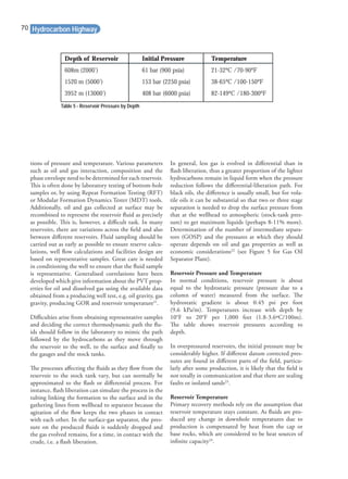
behaviour is that the pressure-temperature plot is no
longer a simple curve as for the single component; in-
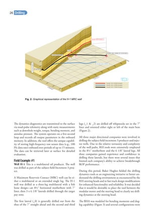
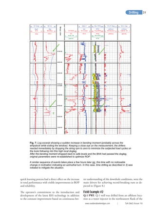
stead it is an ‘envelope’—see Figure 4.
The maximum pressure defined by this envelope is
known as the cricondenbar; above it, the liquid and
gas phases cannot co-exist. The maximum temperature
defined by the envelope (the cricondentherm) is, like-
wise, one above which the two phases cannot co-exist.
The critical point is the point in the envelope at which
the properties of the gaseous and liquid phases become
identical—it is not related in any simple way to the
cricondenbar or the cricondentherm.
The behaviour of the fluid as it leaves the reservoir
(essentially an isothermal environment) and travels
through the production tubing and wellbore to the
separation facilities requires more complex considera-
tions of the thermodynamic behaviour; however, sim-
ple laboratory measurements are sufficient for design
calculations19
.
If the reservoir pressure is at the bubble point, the oil
is said to be saturated. If the reservoir pressure is above
the bubble point, the oil is said to be undersaturated.
An oil reservoir which is discovered with a gas cap is at
its bubble point and is, therefore, saturated. An oil res-
ervoir that is unsaturated describes hydrocarbons above
their bubble point, where the reservoir temperature is
substantially below the critical point and surface GORs
are low to moderate. On production, as the reservoir
pressure drops, gas comes out of the solution (solution
gas drive). The first gas liberated is composed principally
of the lightest components (methane, ethane and pro-
Hydrocarbon Highway68](https://image.slidesharecdn.com/cfa76e45-08f3-4dee-aba3-0f48427aa567-161219084258/85/saudi_arabia_baixa-68-320.jpg)
![Average reservoir temperatures are therefore needed
for laboratory analyses reflecting reservoir conditions.
Reservoir temperatures are used to determine fluid
properties such as viscosity, density, formation volume
factor and gas in solution. Downhole gauges (during
drilling or permanent) are used to measure reservoir
temperature.
If a variation in temperature is detected across a reser-
voir after correcting for depth, an average value can be
calculated and used as a constant reservoir temperature.
For EOR, involving chemical and miscible processes,
changes in temperature affect both the phase behav-
iour of injected and produced fluids, and therefore will
affect recovery. The modelling of such processes must
be accompanied by laboratory tests carried out using
reservoir temperatures. In EOR processes that employ
heat injection, such as steam or in-situ combustion,
reservoir temperatures do not remain constant. In these
cases, the reservoir temperature needs to be monitored
all the time so as to detect the movement of the heat
front25
.
Development of an Oil or Gas Field
Once a discovery has been made, appraisal wells are
drilled to determine the extent of the accumulation.
The important reservoir calculations from the discovery
data are the minimum size of the accumulation and the
minimum size needed for commercial production. The
appraisal wells are then sited to attempt to answer the
question, ‘Is this economic?’ rather than ‘How large is
it?’ With each appraisal well comes a refinement of the
geological model of the accumulation, as represented
by maps and cross-sections, and a new economic as-
sessment. If it becomes obvious that the accumulation
contains sufficient oil or gas to be considered commer-
cial, development plans will be formulated. The sit-
ing of development wells is different from that of the
appraisal wells, as now the purpose is to produce the
petroleum as efficiently as possible at the lowest unit
cost. If the field is complex, with multiple reservoirs
and faulting, the most efficient well-spacing may be
initially difficult to decide as each fault block may have
to be regarded as separate accumulations. Over time
production of fluids from the reservoir will change
fluid pressure and flow rates. Production engineers will
critically examine these factors to ensure that produc-
tion can maximised over the life of the field.
Readers note; reservoir and reservoir fluid character-
istics are well covered in industry texts. Physical and
chemistry texts provide the background to PVT behav-
iour, single and multi phase fluid flow.
References
1. Crude oil volumes are still reported in barrels and
in some cases in tonnes. However, the number of bar-
rels contained in a tonne varies according to the type
and specific gravity of the crude involved. An average
number would be around 7.33 barrels per ton. Surface
oil is reported at stock-tank (st) conditions, with vol-
umes in cubic metres (m3) or barrels [stb, or (st)bbl].
2. API What a barrel of crude oil makes. API
Factsheet.
3. See Petrobras Technology Harts E & P, June 2003
p45 for heavy oil definition below 19ºAPI.
4. TTNRG Nature’s Best Wajid Rasheed.
5. Pricing differential is due to higher proportion of
heavier and sourer (high sulphur) crudes that relative
to light sweet production. More than half the world’s
produced oil is heavy and sour in quality and this pro-
portion is expected to increase. This depends on the
crude oil’s molecular structure and sulphur content.
The oil will be classified accordingly and priced us-
ing reference crudes. Some of the common reference
crudes are: West Texas Intermediate (WTI), Brent
blend from the East Shetland Basin of the North
Sea. Dubai-Oman, used as benchmark for Middle
East sour crude oil flowing to the Asia-Pacific region,
Tapis (from Malaysia, used as a reference for light
Far East oil), Minas (from Indonesia, used as a refer-
ence for heavy Far East oil), The OPEC Reference
Basket, a weighted average of oil blends from member
countries.
6. The compositions of different crudes are measured
and published in assays. Refining engineers use assays
to decide which crudes will be required to formulate
products.
7. API 5 RP 44 Sampling Petroleum Reservoir Fluids
Proper management of production from a natural gas
or petroleum reservoir can maximize the recovery of
the hydrocarbon fluids (gas and oil) originally in the
reservoir. Developing proper management strategies
requires accurate knowledge of the characteristics of
the reservoir fluid. Practices are recommended here-
in for obtaining samples of the reservoir fluid, from
which the pertinent properties can be determined by
subsequent laboratory tests.
8. For gas wells, the inverse ratio is sometimes used and
the liquid-gas ratio is expressed in barrels per million
m3
(or million cubic feet).
Hydrocarbon Highway
www.saudiarabiaoilandgas.com | SA O&G Issue 10
71](https://image.slidesharecdn.com/cfa76e45-08f3-4dee-aba3-0f48427aa567-161219084258/85/saudi_arabia_baixa-71-320.jpg)


The document discusses several topics related to oil and gas exploration and production technologies: 1. Baker Hughes advertises its reservoir consulting services and technologies that can help customers understand reservoir economics, lower costs, improve productivity and increase ultimate recovery. 2. The newsletter announces an upcoming SPE technical symposium in Saudi Arabia focused on innovative technologies for maximizing performance and production. 3. Saudi Aramco researchers were awarded a patent for a new method of processing geoseismic data that enhances detection of subsurface anomalies and accurately estimates dip and azimuth to reveal geologic structures.


