The document discusses power factor correction methods to improve the efficiency of non-linear load circuits by eliminating the fluctuating effects of reactive power. It categorizes loads into linear and non-linear, explains harmonics and their impact on power systems, and outlines advantages and disadvantages of different correction methods: passive, active, and dynamic. Key methods include using power filters, power electronics, and real-time techniques to stabilize electrical systems and reduce losses.
CONTENTS:
Abstract.
Introduction.
Loads types: 1. Linear Loads.
2. Non-Linear Loads.
The Reasons of Harmonics.
What are Harmonics ?
The Power Factor.
Disadvantage of Low Power Factor.
Power Factor Parts: 1. Displacement P.F.
2. Distortion P.F.
Power Factor Correction Methods: 1. Passive P.F.C.
2. Active P.F.C.
3. Dynamic P.F.C.
Techniques of P.F.C. Methods In Some Applications.
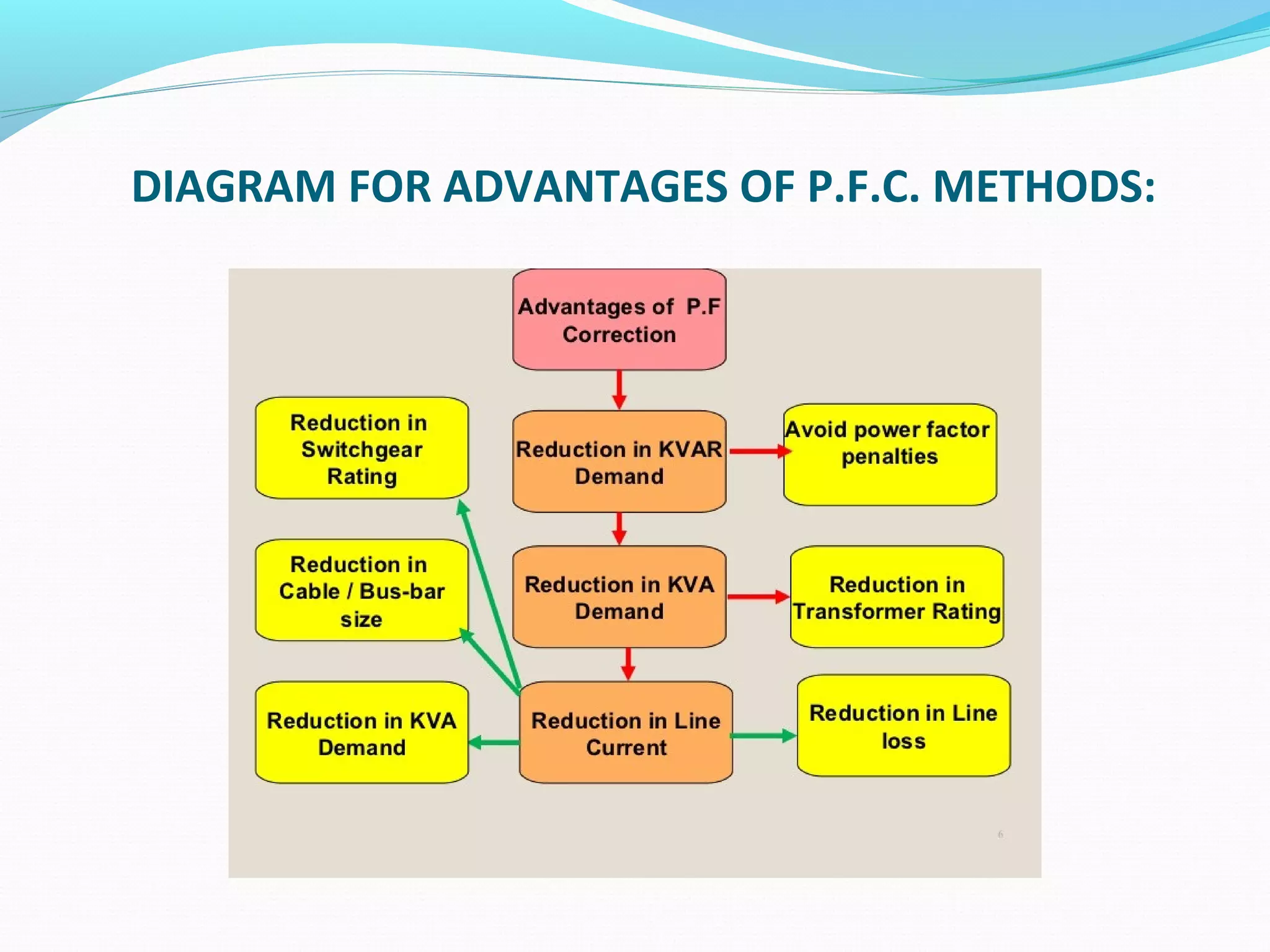
P.F.C.’s Advantages Diagram.
Conclusion.
3.
we will introducein this presentation some
methods that are used for converting the non-linear
load circuits into that linearity. In order to rise its
efficiency and to be utilizing of the entire real power,
by deleting the continuous fluctuating effect of the
reactive power. All in all, we can get this via power
factor correction methods.
4.
Generally, the directionof power transmission must be from
the source to the load, in order to give useful energy and it is
represented in consumed real power(P)during the time. Also, this
real power is always absorbed in the resistors only. Meanwhile, the
direction of reactive power(Q)is fluctuating(Bi-directional)from the
source to the load and vise versa, by the capacitors and the
inductors in load circuits. Since, the inductors(reactors) are
consuming(sink)the reactive power(+Q), and the capacitors are
charging(generate)reactive power(-Q) in the loads. Whereas, these
processes(sinking & generating)for reactive power, have been
disturbing the voltage source and causing power losses.
All in all, it is necessary to improve load circuits and to make
the power in one direction, through deriving just the real power(P)by
using a suitable power factor correction method for this important
target.
5.
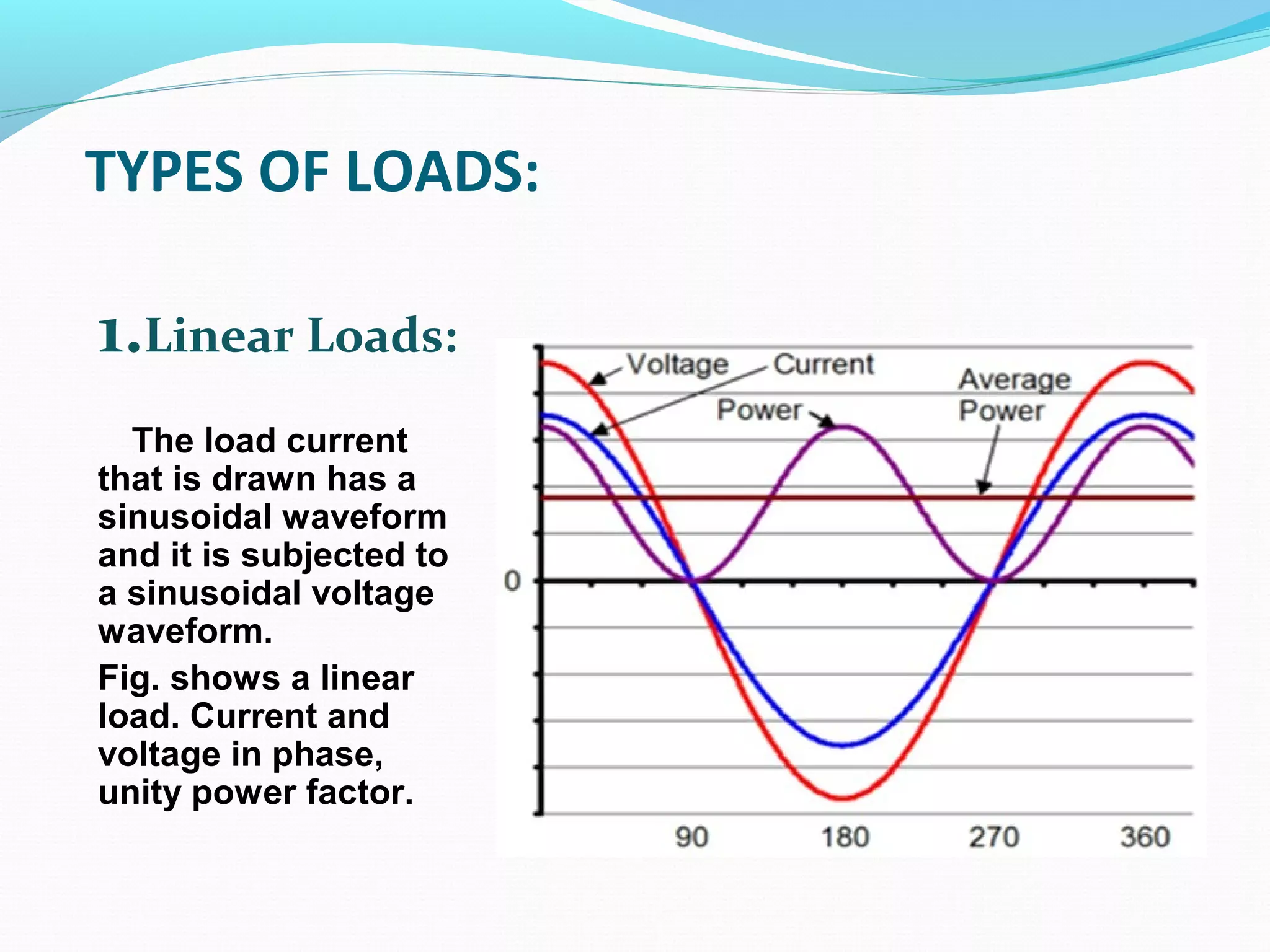
TYPES OF LOADS:
1.LinearLoads:
The load current
that is drawn has a
sinusoidal waveform
and it is subjected to
a sinusoidal voltage
waveform.
Fig. shows a linear
load. Current and
voltage in phase,
unity power factor.
6.
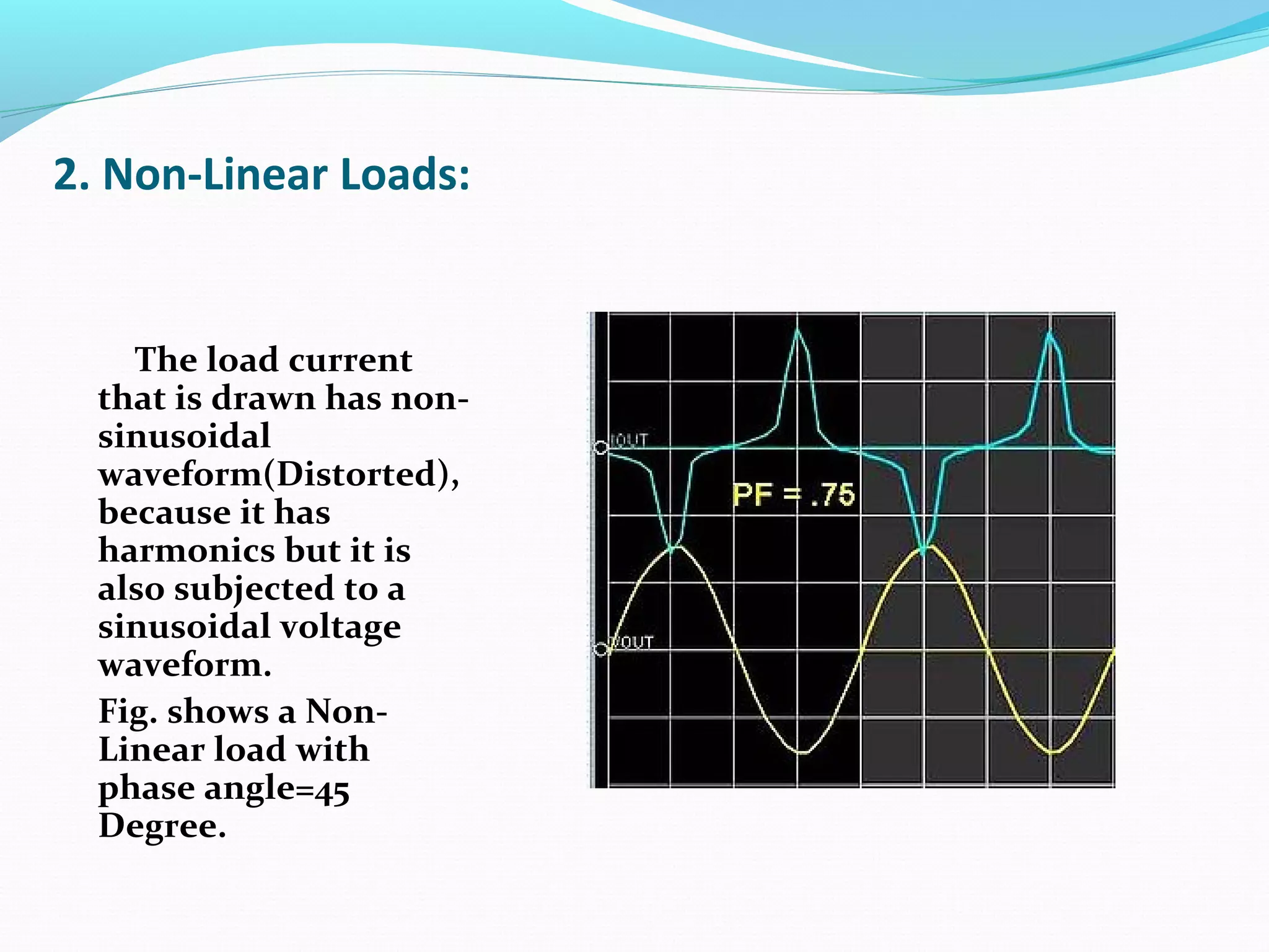
2. Non-Linear Loads:
Theload current
that is drawn has non-
sinusoidal
waveform(Distorted),
because it has
harmonics but it is
also subjected to a
sinusoidal voltage
waveform.
Fig. shows a Non-
Linear load with
phase angle=45
Degree.
7.
The main reasonsare:
•Loads nature ; is non-linear such as heavily inductive
loads.
•Non-Linear loads; as the Power Electronics devices ,
fluorescent lamps, arc furnaces,…, e .t .c .
•Operational oscillation of network; where the
automatic loading change results to un balanced
loading in network.
8.
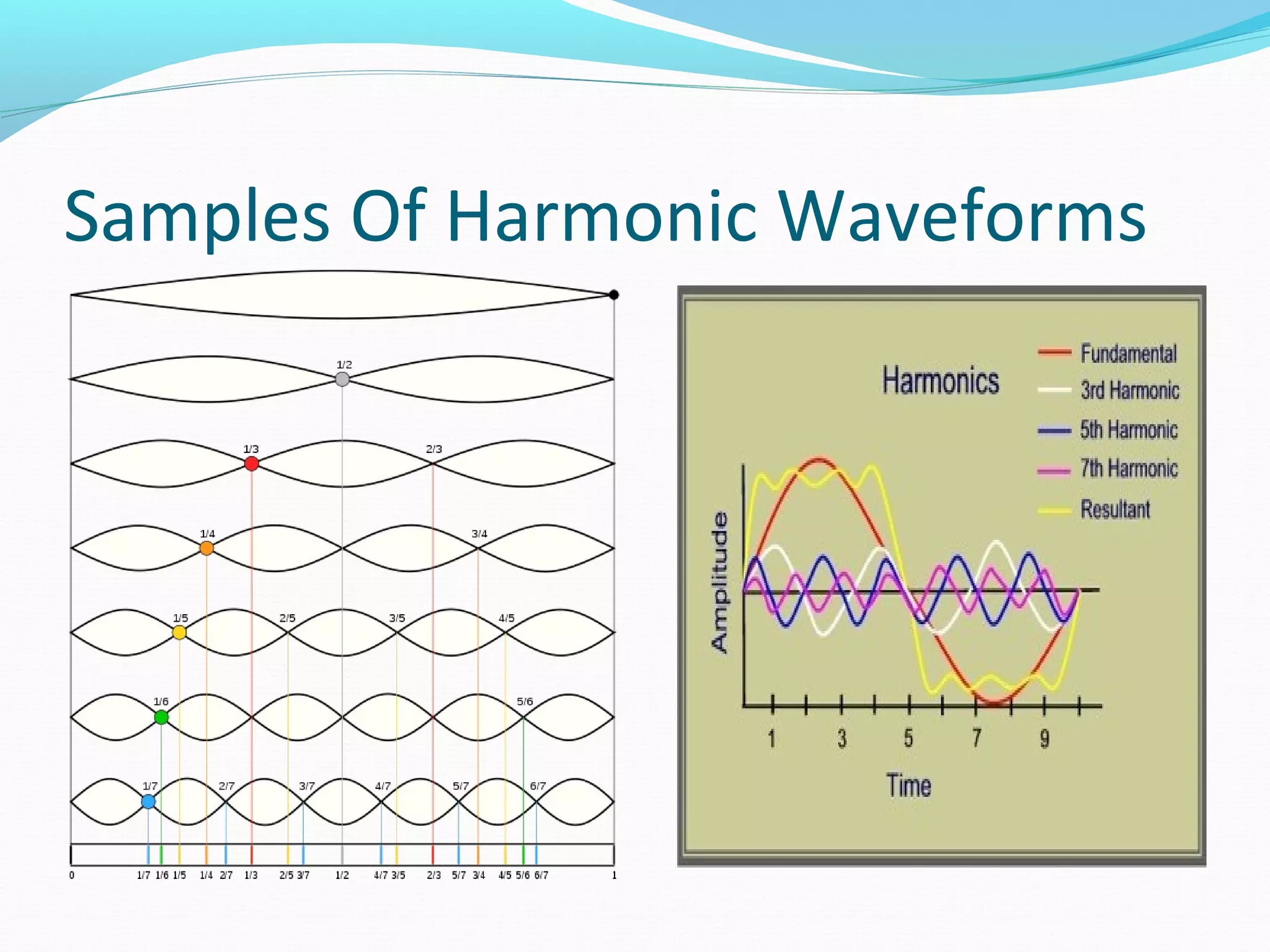
The distortion waveformof current or(voltage) in non-
linear load is analyzing into a big integer number of the
sinusoidal components. The first component is called the
fundamental and it has the same frequency of the source, and it
apply on it(In phase) generating real power in the load.
Whereas, the other sinusoidal components have a high
frequencies(or; multiple of fundamental’s frequency. So, they
are not applying on source voltage wave. In addition, each one
has a certain amount of reactive power(+Q or –Q)according to
that of current’s lagging or leading, with respect to applied
source voltage in the load circuits.
By summation of the components’ reactive powers, we get
a total reactive power of the distorted load current wave. If
these harmonics are not treated or corrected, it will cause more
losses in a complex power(S)of the voltage source and they
make(Distort)the sinusoidal source current waveform because
of its high frequencies.
9.
These harmonic componentsare making(Hysteresis and
Eddy currents)losses in the synchronous machines, because of
their high frequencies.
The(3rd
)third harmonic component in three phases system
causes heating losses in(Y-connection), it makes(overload
heating)because of the high current(over current)flowing in the
neutral wire. Also, it makes (Copper Losses)in(Delta-
connection), because of its circulating around in three phase
windings.
Additionally, in three phases system some of these
components which have a negative-sequence such as(5th
, 7th
,
11th
), so they have a (-ve torques); that cause a mechanical
Losses(rotating torque decreasing & vibration due to its high
frequency) in the large synchronous machines.
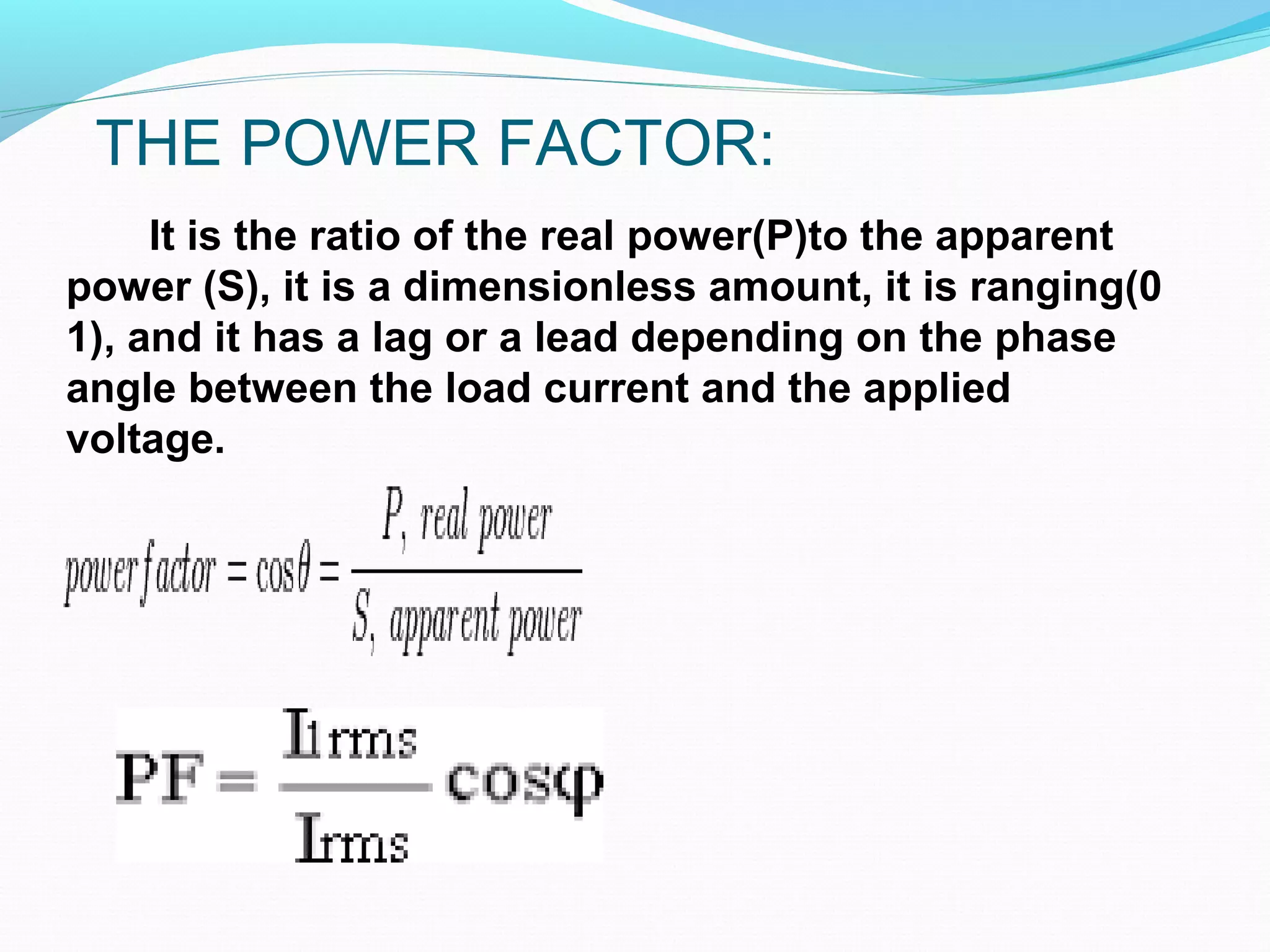
THE POWER FACTOR:
Itis the ratio of the real power(P)to the apparent
power (S), it is a dimensionless amount, it is ranging(0
1), and it has a lag or a lead depending on the phase
angle between the load current and the applied
voltage.
12.
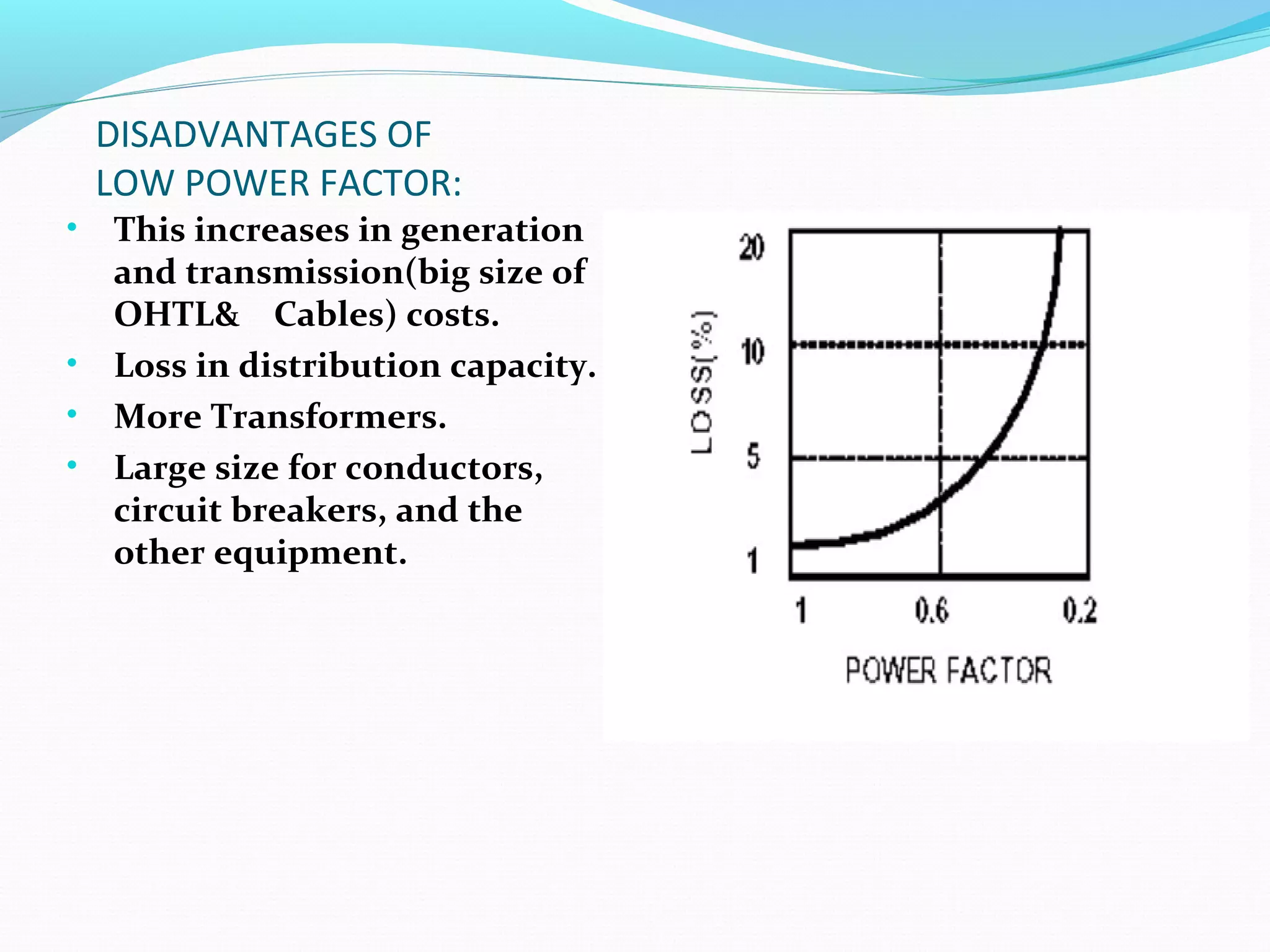
DISADVANTAGES OF
LOW POWERFACTOR:
• This increases in generation
and transmission(big size of
OHTL& Cables) costs.
• Loss in distribution capacity.
• More Transformers.
• Large size for conductors,
circuit breakers, and the
other equipment.
13.
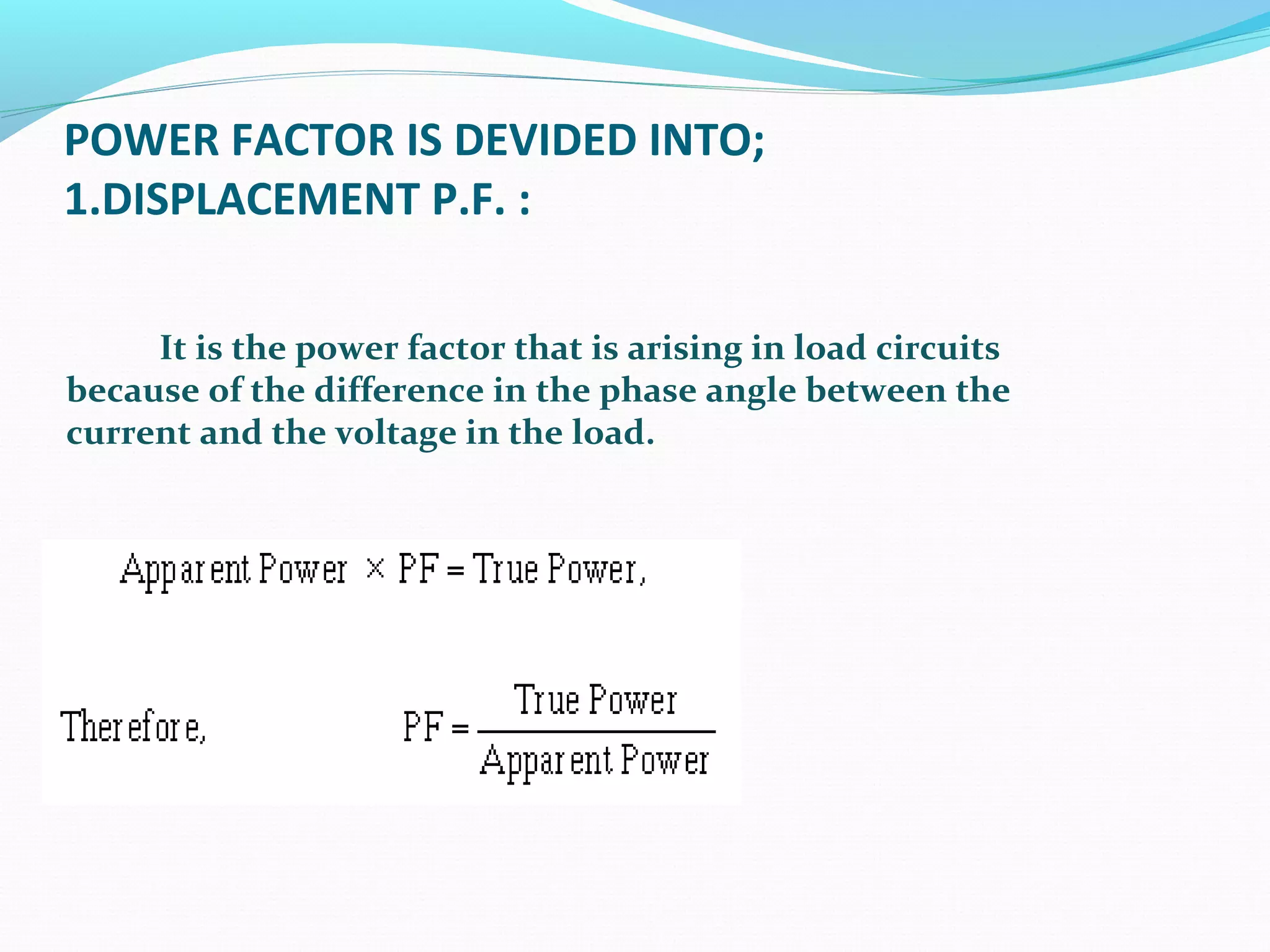
POWER FACTOR ISDEVIDED INTO;
1.DISPLACEMENT P.F. :
It is the power factor that is arising in load circuits
because of the difference in the phase angle between the
current and the voltage in the load.
14.
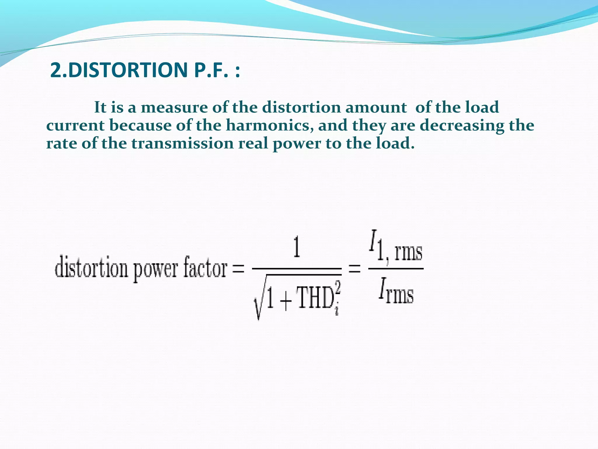
2.DISTORTION P.F. :
Itis a measure of the distortion amount of the load
current because of the harmonics, and they are decreasing the
rate of the transmission real power to the load.
15.
1.PASSIVE P.F.C. METHOD:
This method is more ease for controlling on the load
harmonic distorted current. Because, it uses a power filter and
the later is passing of the load distorted current at one specific
frequency(source frequency)only. This filter is consisting of
group of capacitors and connection contactors.
Its disadvantages are:
•It needs more capacitors and contactors to operate.
•Its P.F. values are low, it range(0.6-0.7-0.8)
This method has two ways(methods) in using:
A- Static Method:
B- BULK Method.
16.
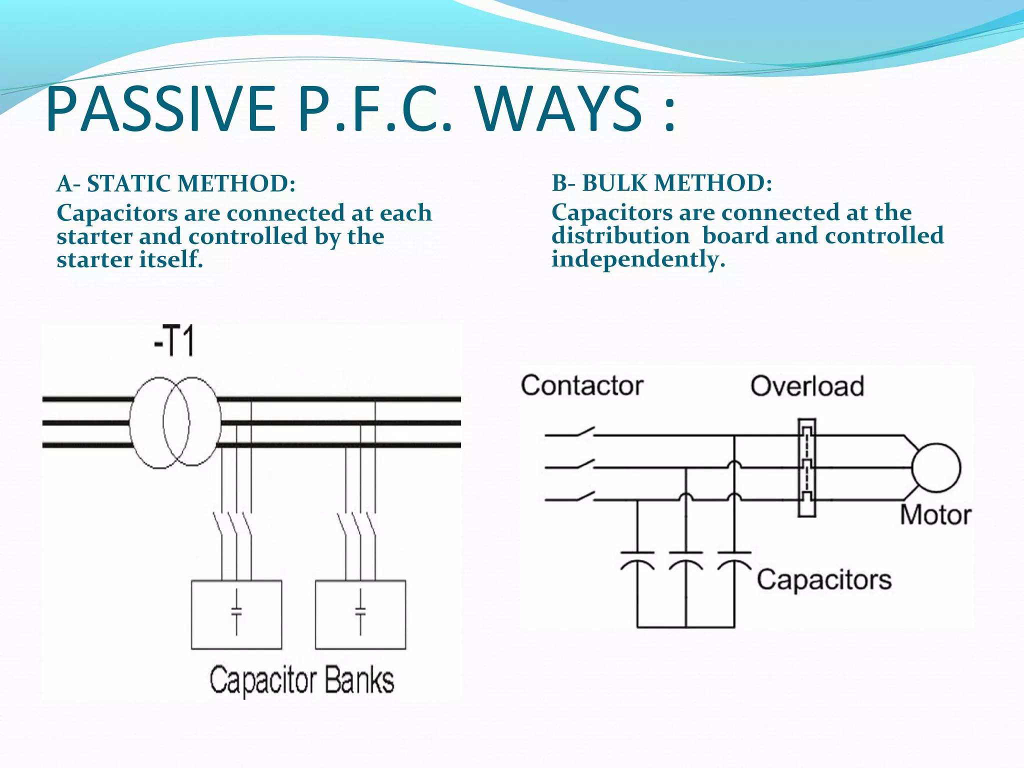
PASSIVE P.F.C. WAYS:
A- STATIC METHOD:
Capacitors are connected at each
starter and controlled by the
starter itself.
B- BULK METHOD:
Capacitors are connected at the
distribution board and controlled
independently.
17.
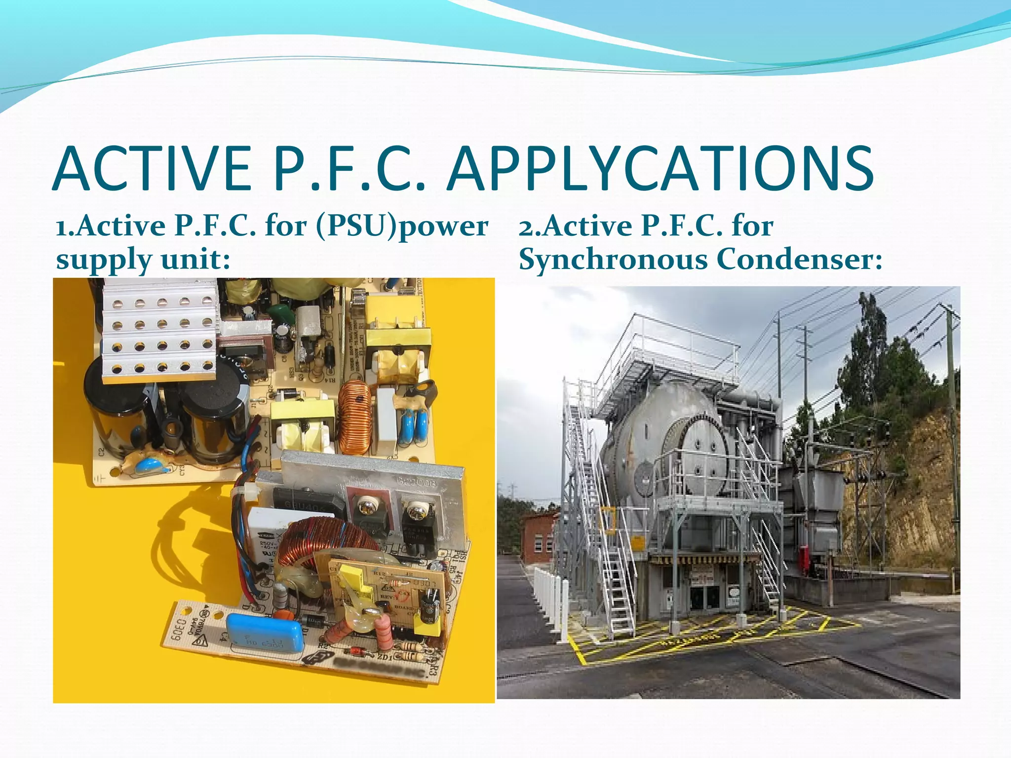
2. ACTIVE P.F.C.METHOD:
This method has a very good P.F. ,because it is ranging
from(0.90)to(0.95), so it is better than the previous method.
Also, this method has two main ways(methods), are:
A- Using of the Power Electronics devices in order to change
the waveform of the load distorted current. This is happening
by releasing an Anti-Harmonic waves in load circuit to improve
its power factor. This way may be done in single or multi-stage.
B- By using the Synchronous Condenser(or, No-Load
Synchronous Motor)method, whereas it is controlling in
excitation field current and for making it a lead to eliminate the
inductive effect of the load circuit. Beside, it is placed near of
the power generation plants.
POWER FACTOR CORRECTIONMETHODS:
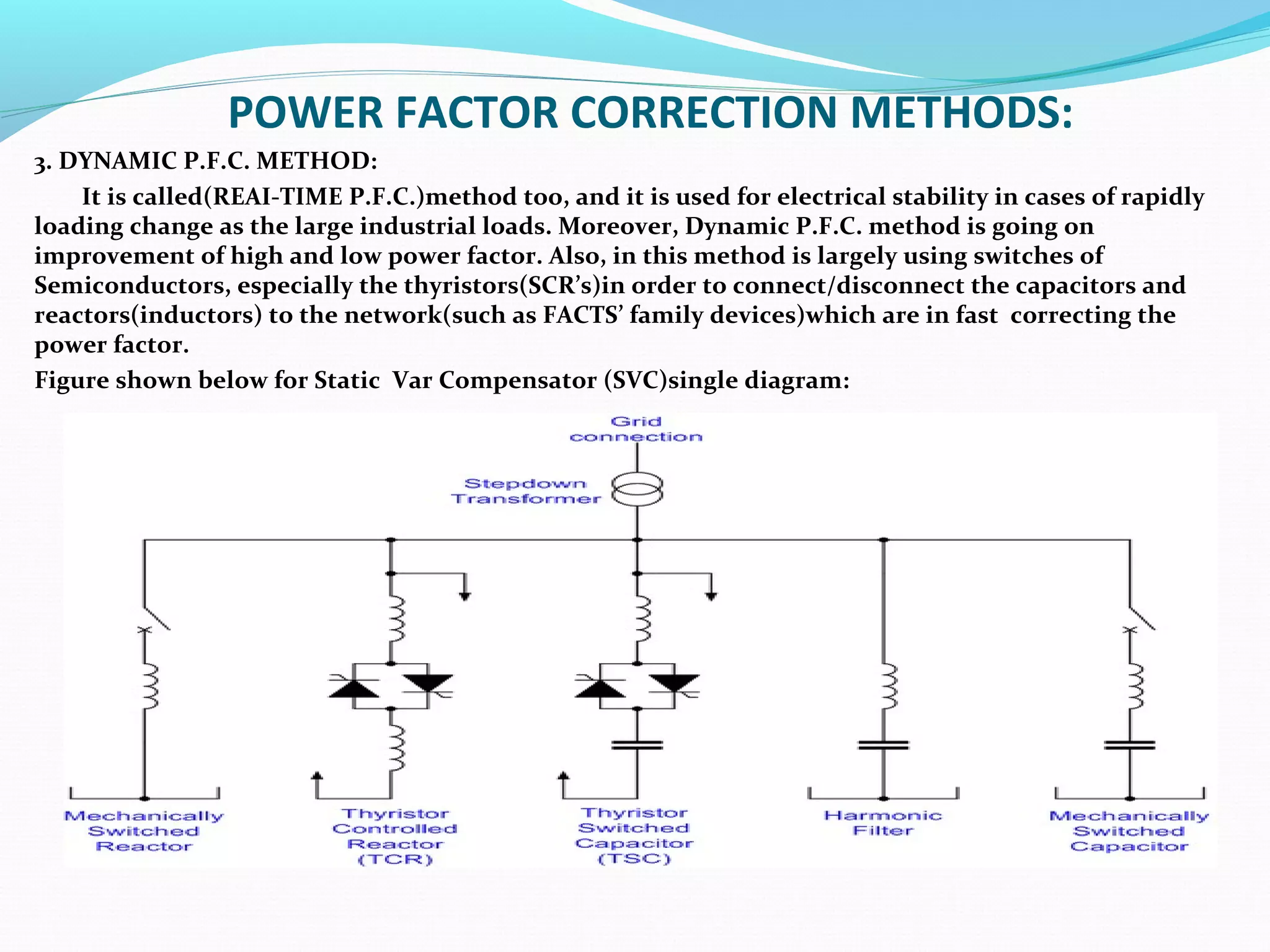
3. DYNAMIC P.F.C. METHOD:
It is called(REAI-TIME P.F.C.)method too, and it is used for electrical stability in cases of rapidly
loading change as the large industrial loads. Moreover, Dynamic P.F.C. method is going on
improvement of high and low power factor. Also, in this method is largely using switches of
Semiconductors, especially the thyristors(SCR’s)in order to connect/disconnect the capacitors and
reactors(inductors) to the network(such as FACTS’ family devices)which are in fast correcting the
power factor.
Figure shown below for Static Var Compensator (SVC)single diagram:
20.
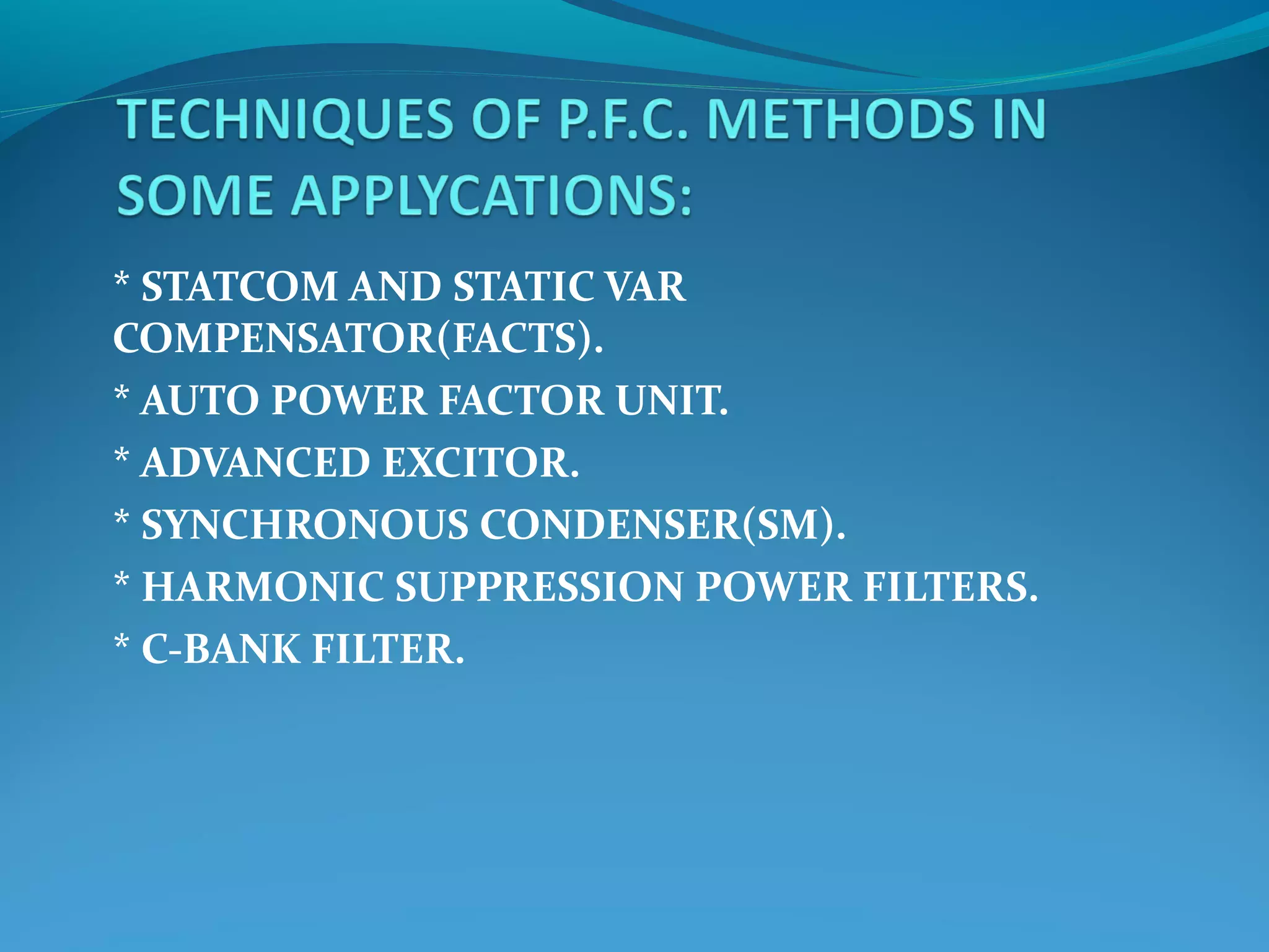
* STATCOM ANDSTATIC VAR
COMPENSATOR(FACTS).
* AUTO POWER FACTOR UNIT.
* ADVANCED EXCITOR.
* SYNCHRONOUS CONDENSER(SM).
* HARMONIC SUPPRESSION POWER FILTERS.
* C-BANK FILTER.
More efforts areexerted in development and
detection of the new techniques to improve the power
factor, let to utilize of the electrical energy is large.
Also, to benefit of the economic operation of the
power system without losses. Finally, the lowest costs
for both the consumer and the supplier, and getting
assimilation for more distribution capacity at the
same generated energy amount.


![Kvar Presentation Ppt 8.8.08[1]](https://cdn.slidesharecdn.com/ss_thumbnails/kvarpresentationppt8-8-081-090713082239-phpapp01-thumbnail.jpg?width=640&height=640&fit=bounds)


