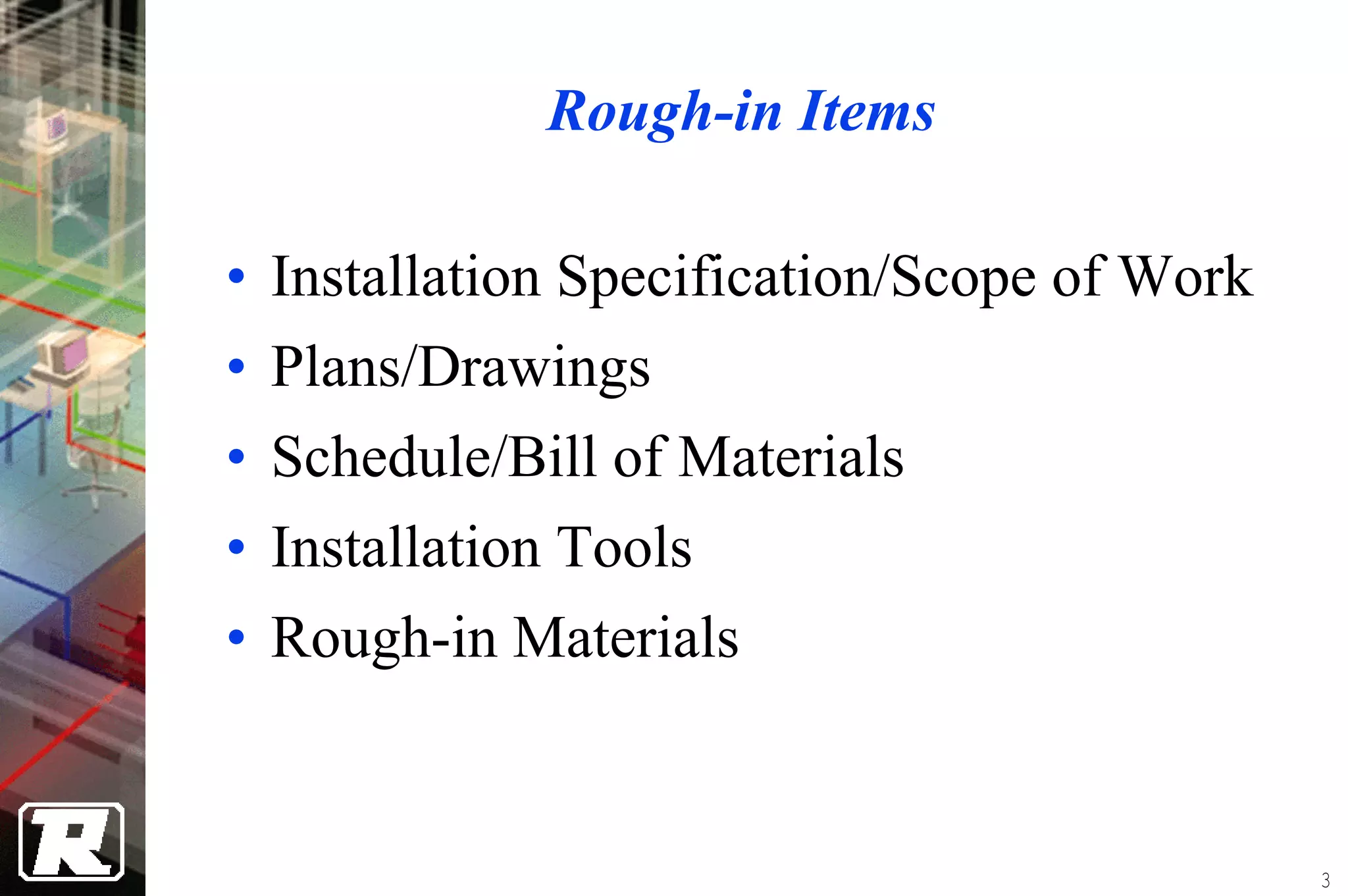
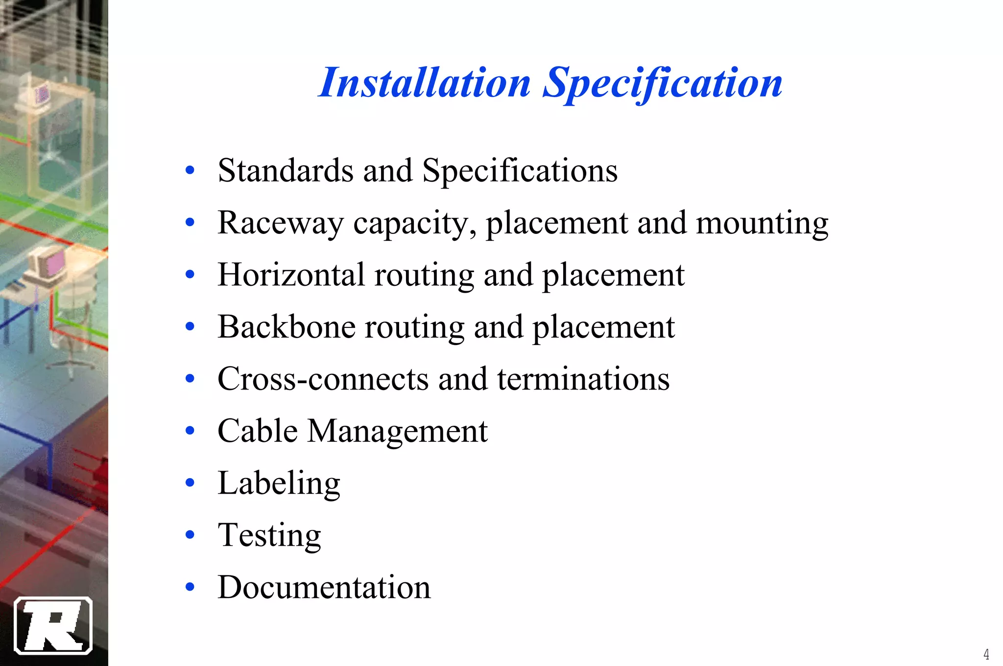
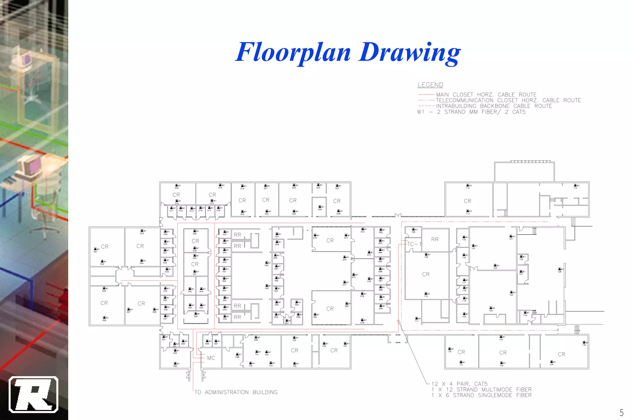
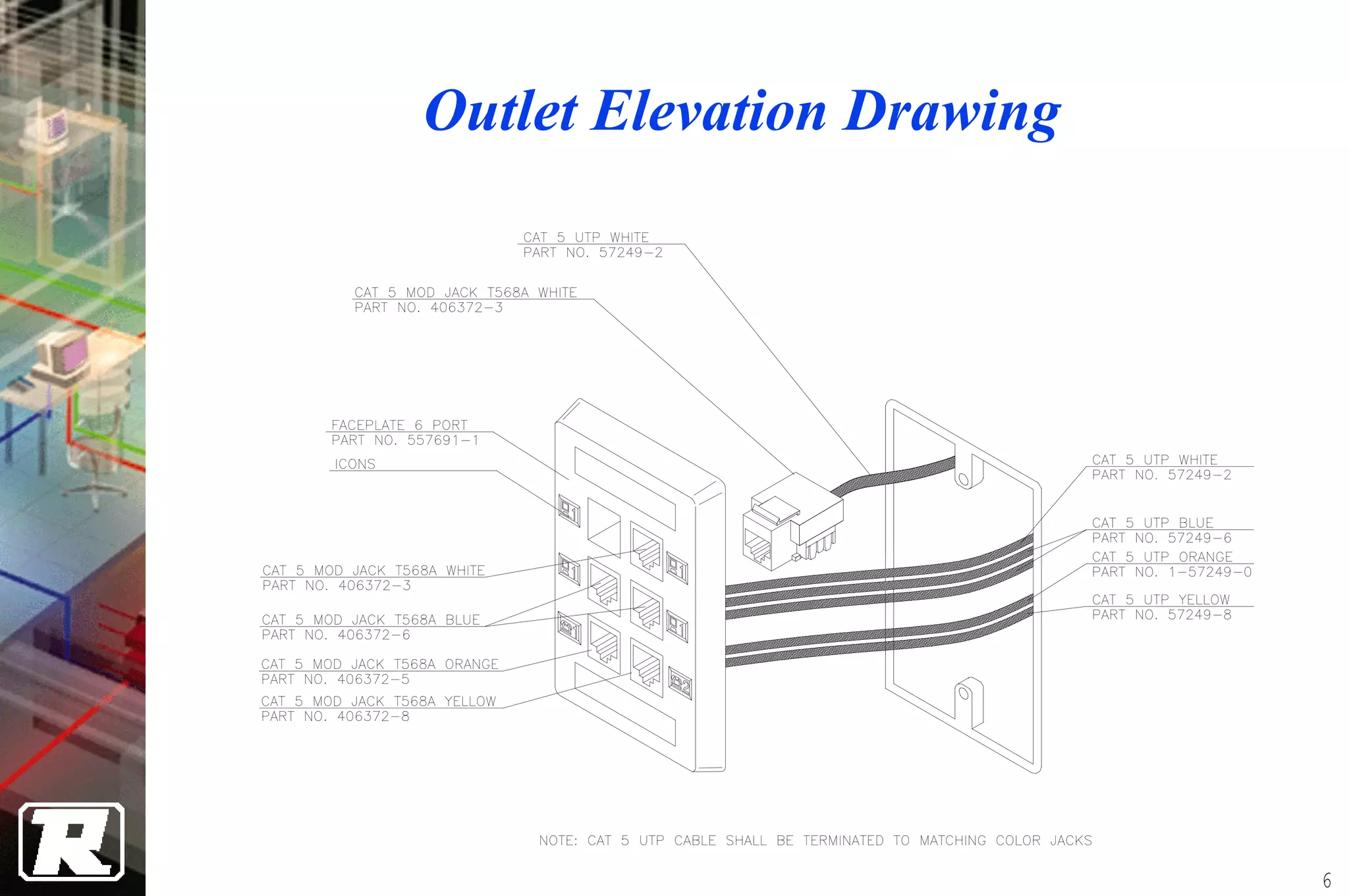
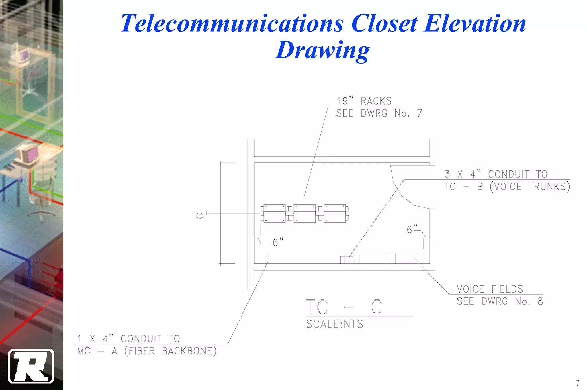
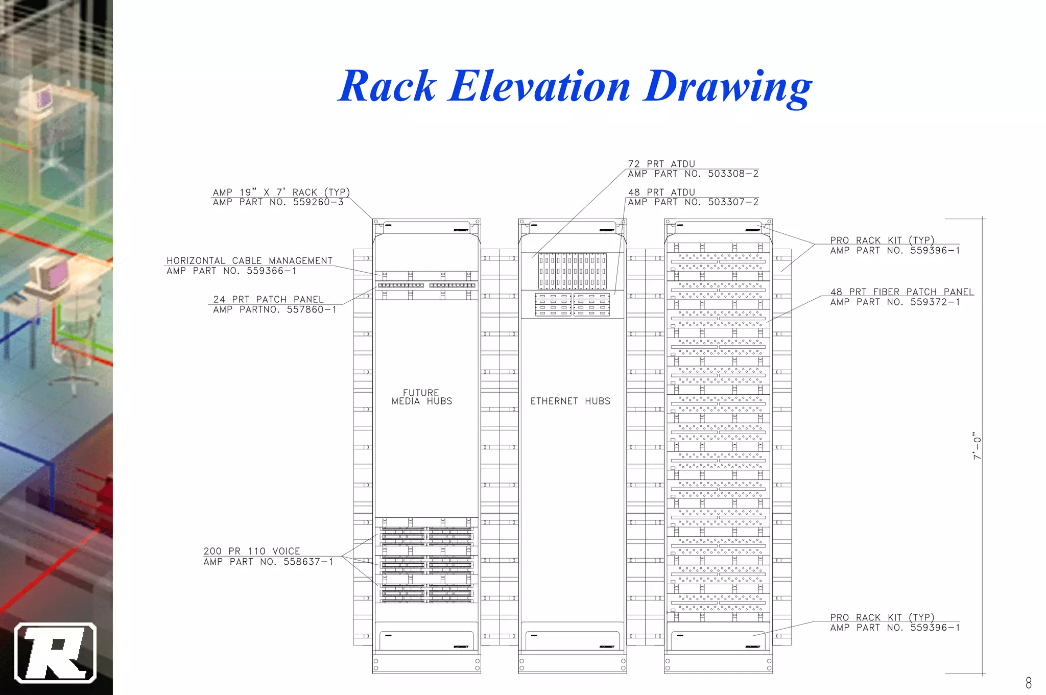
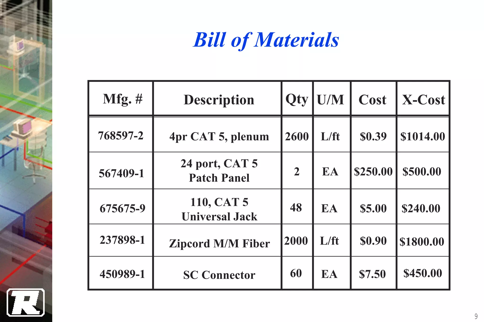
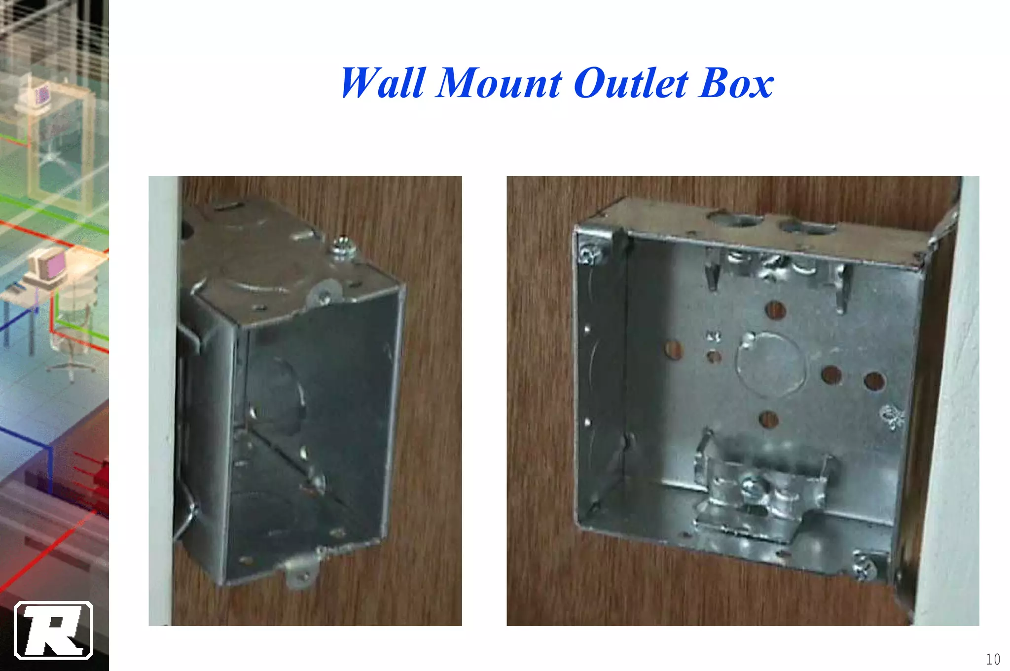
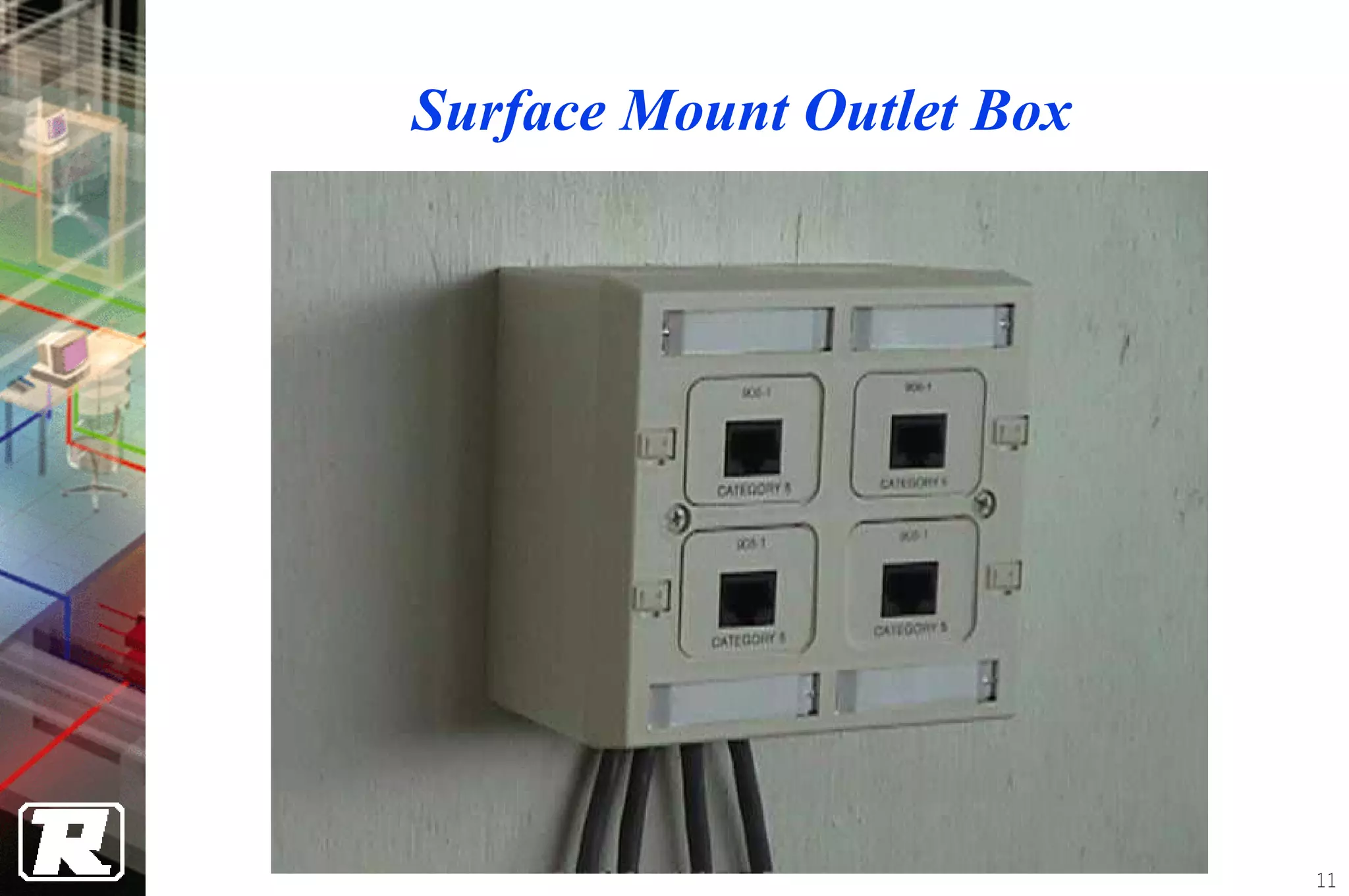
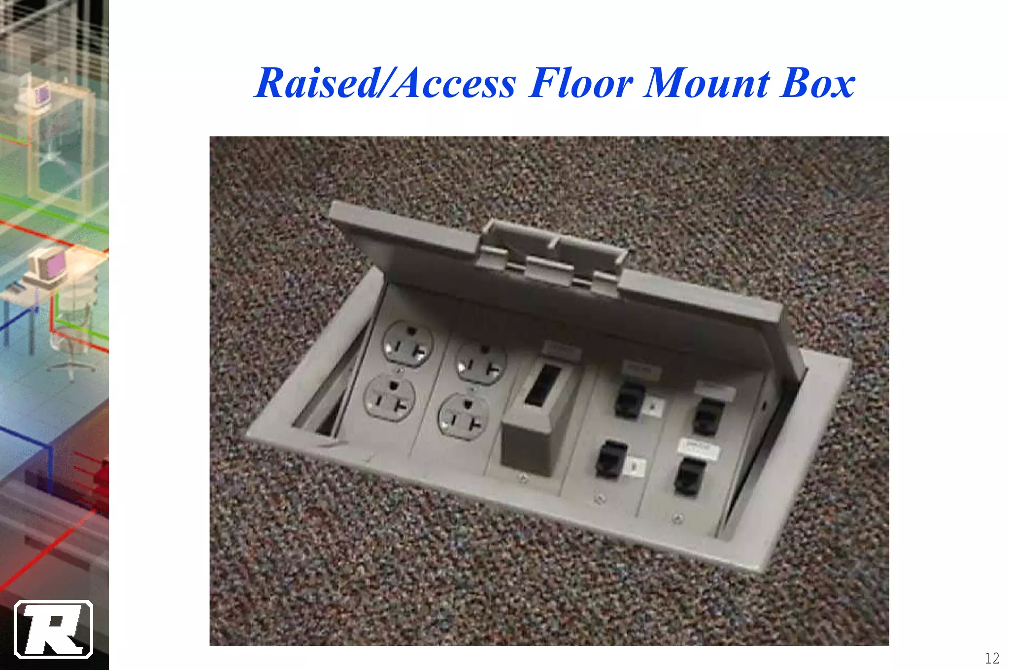
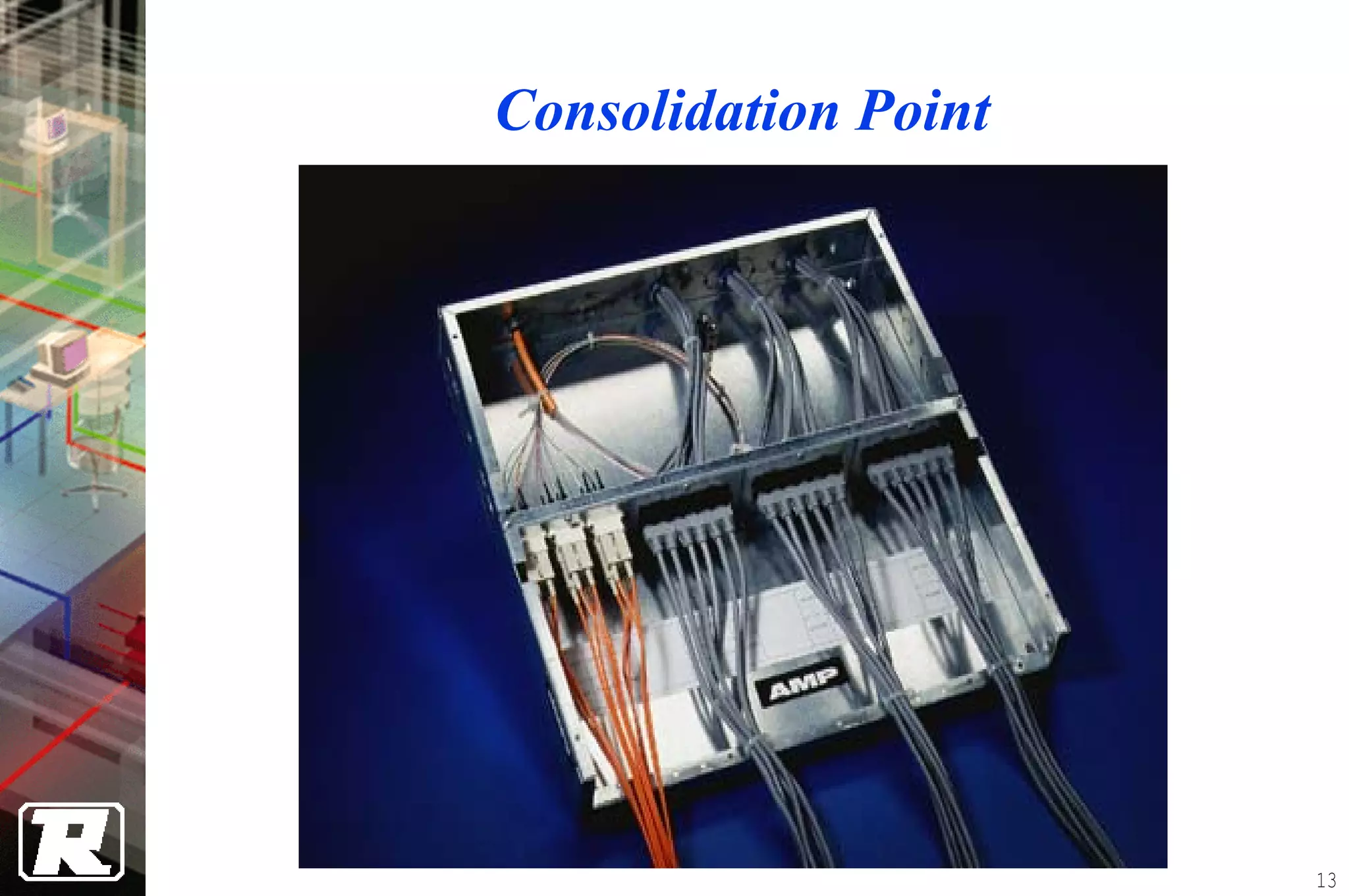
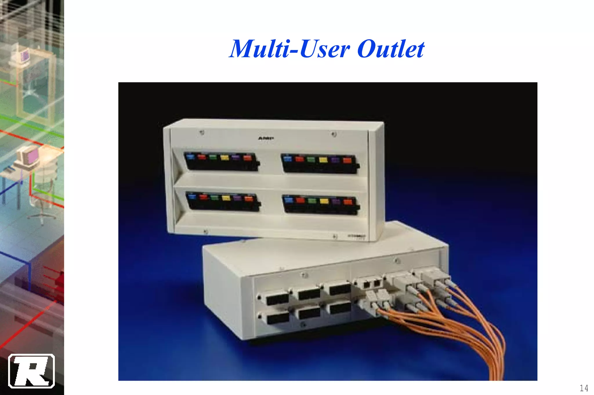
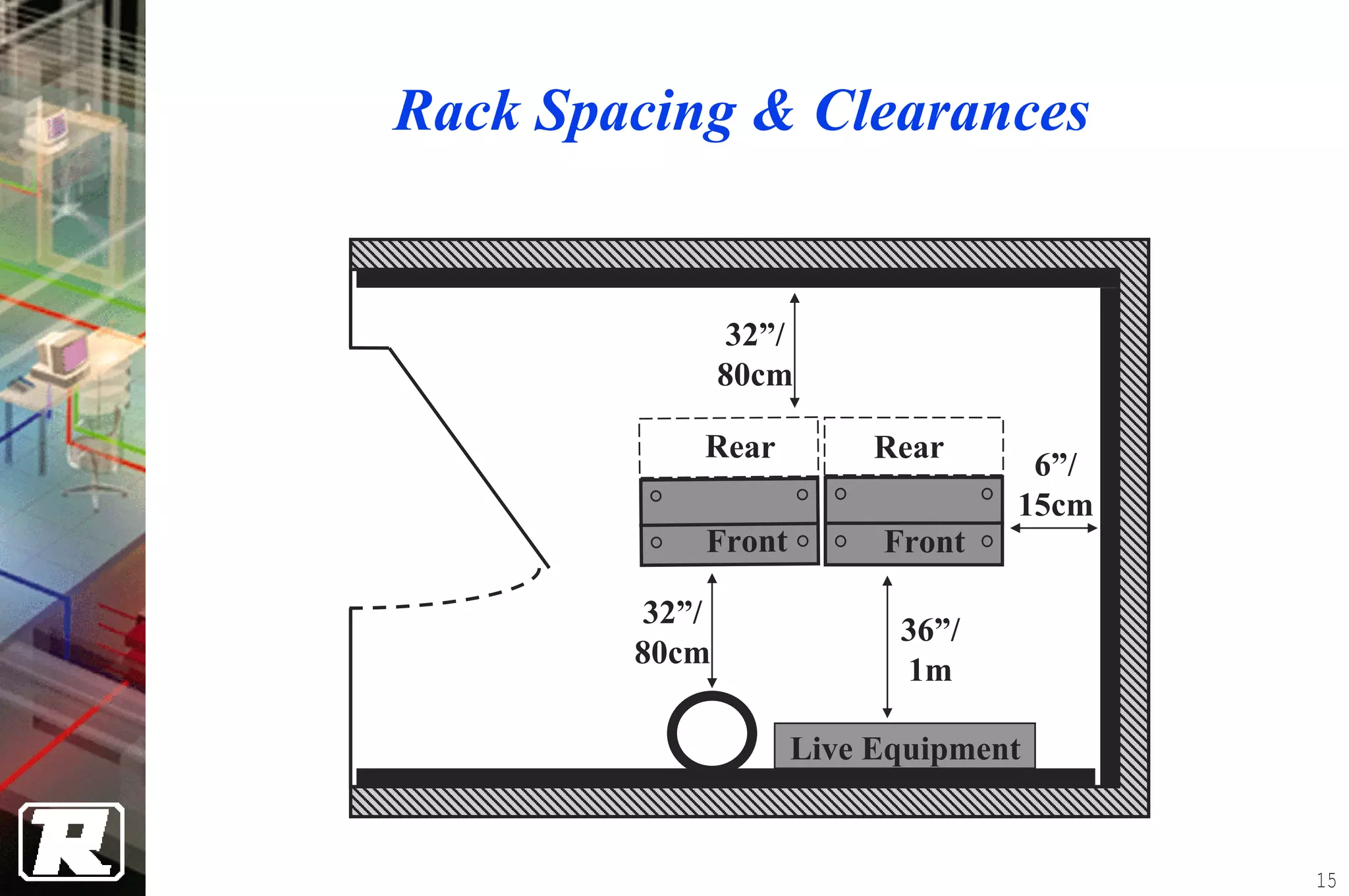
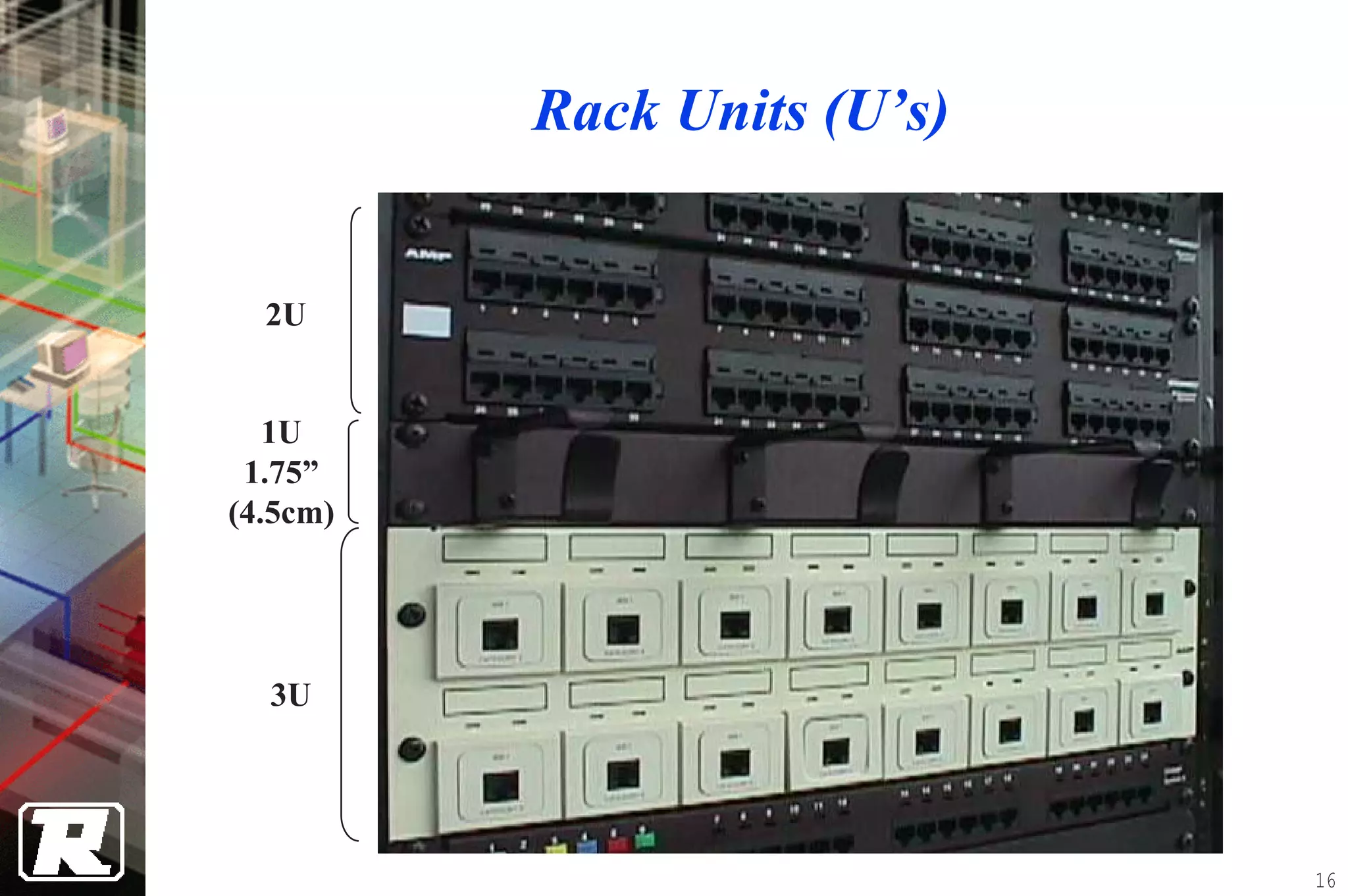
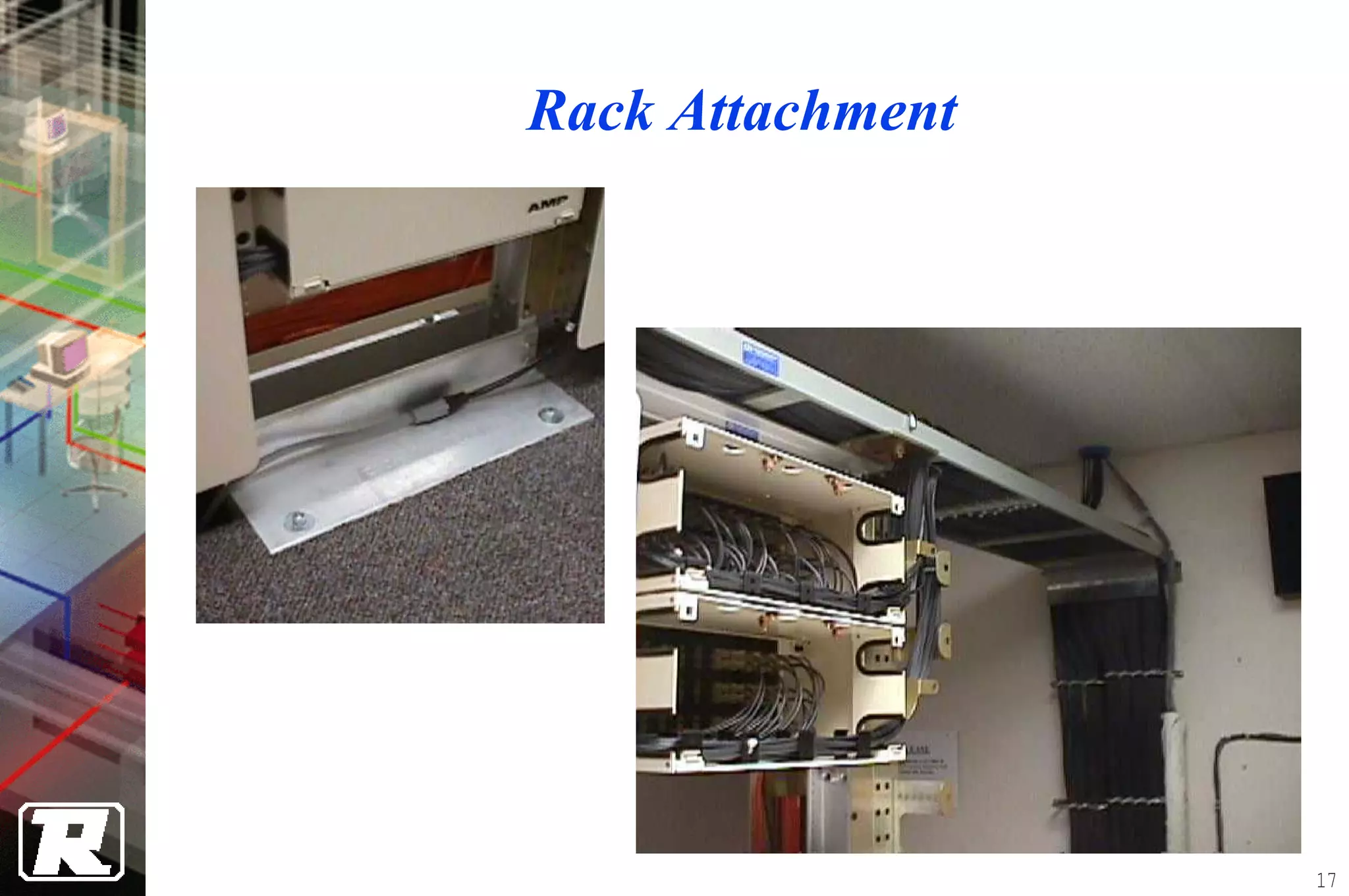
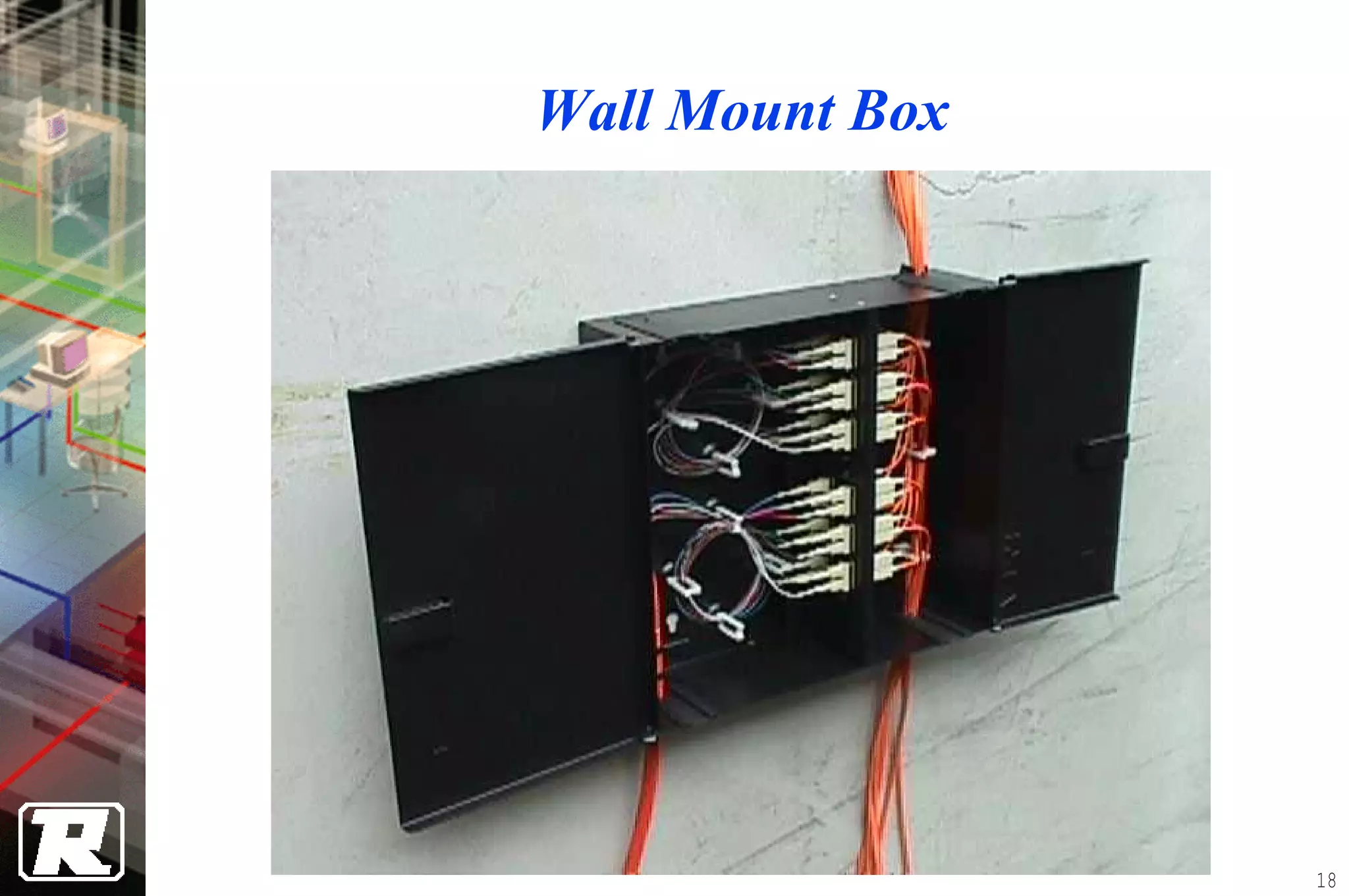
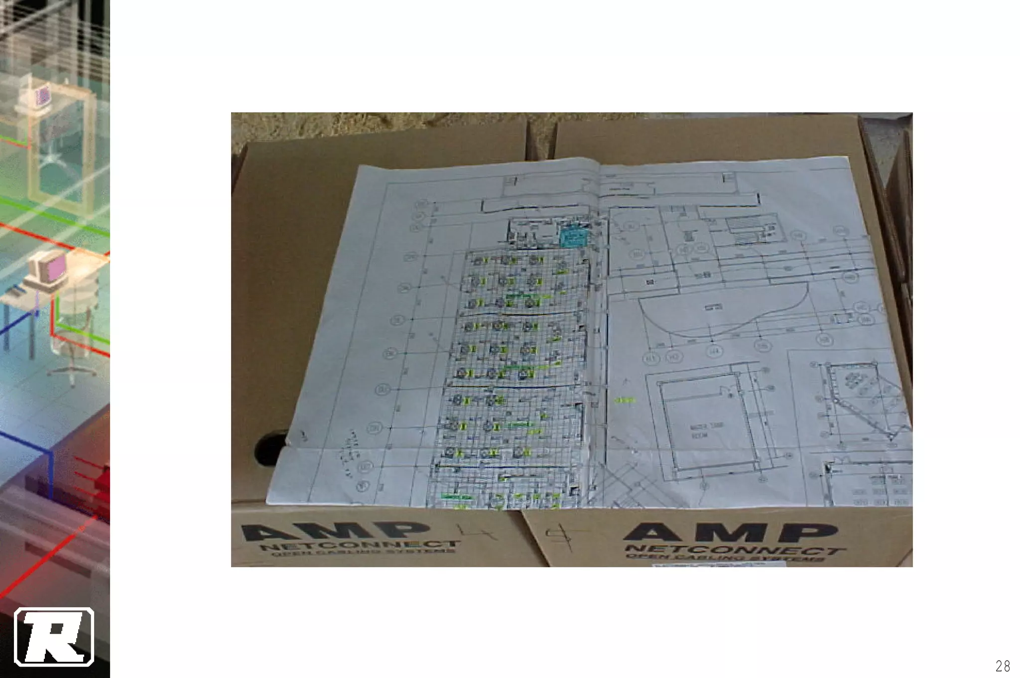
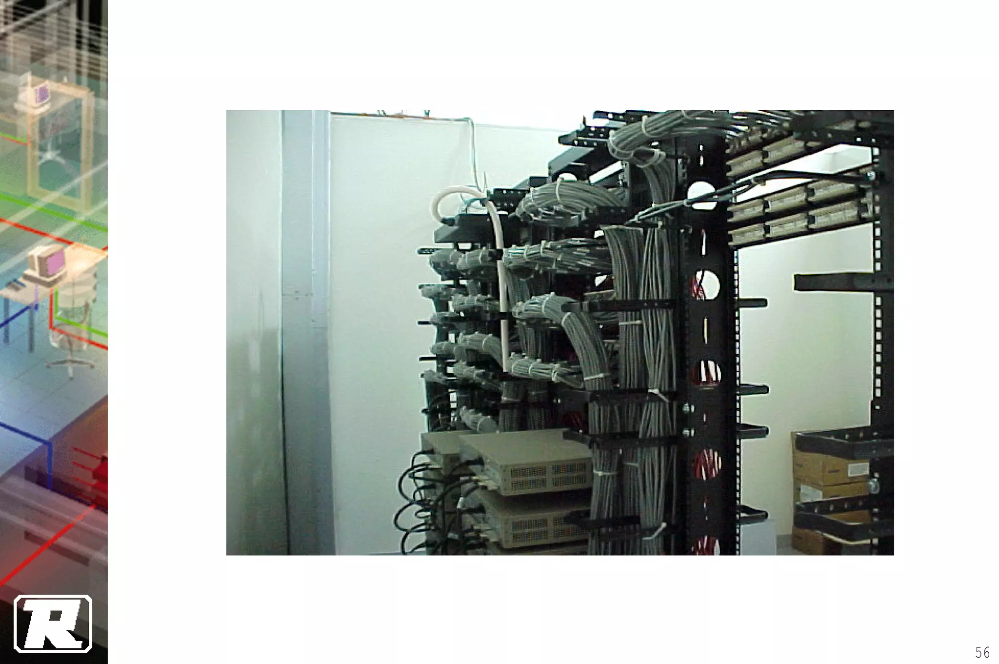
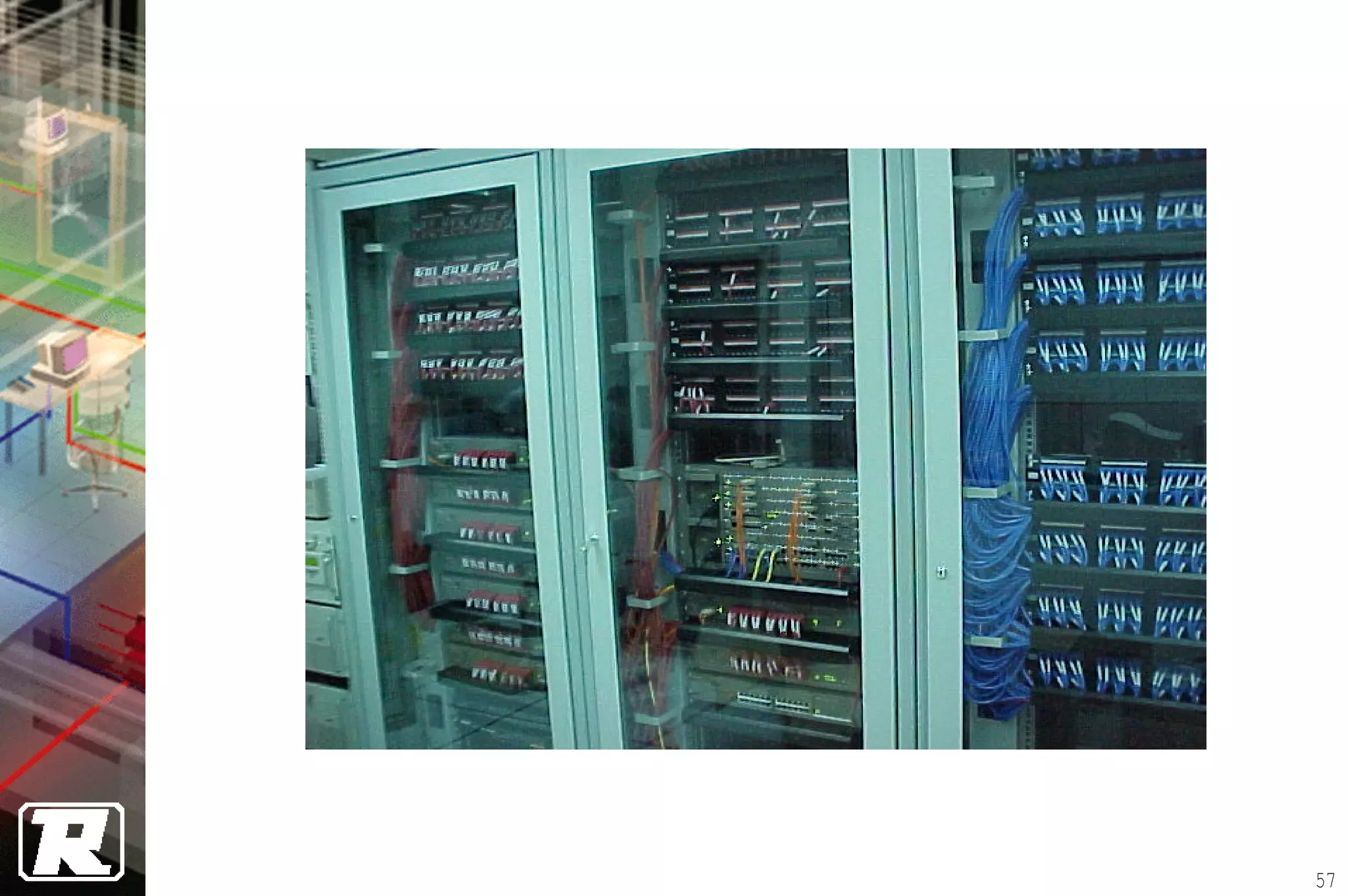
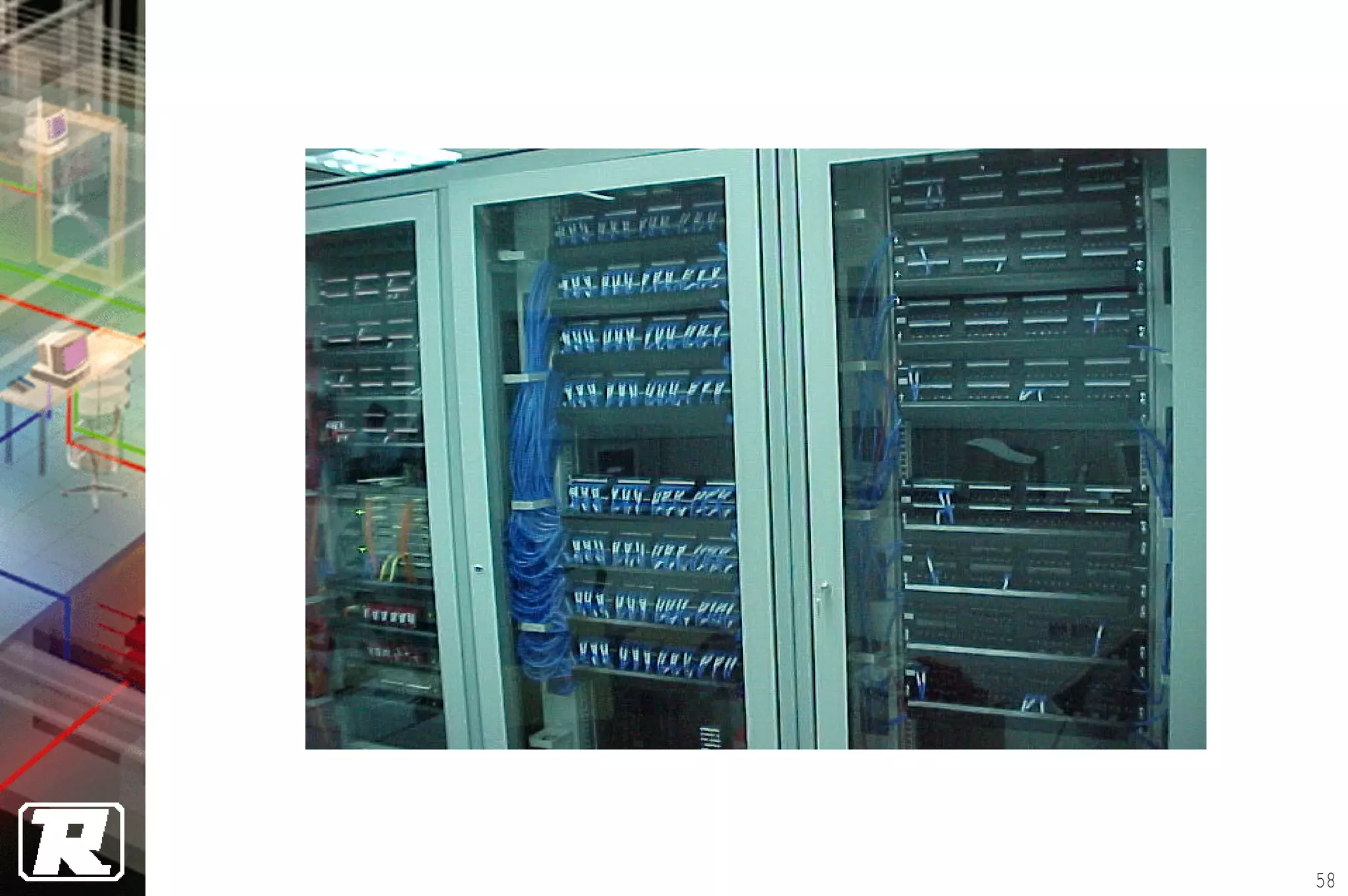
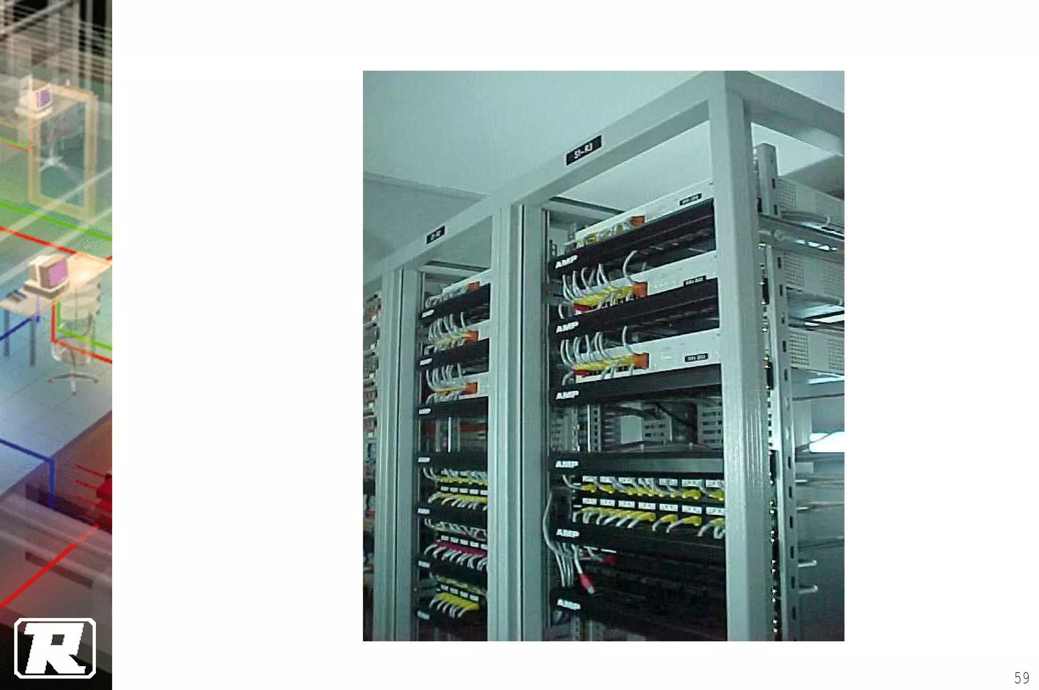
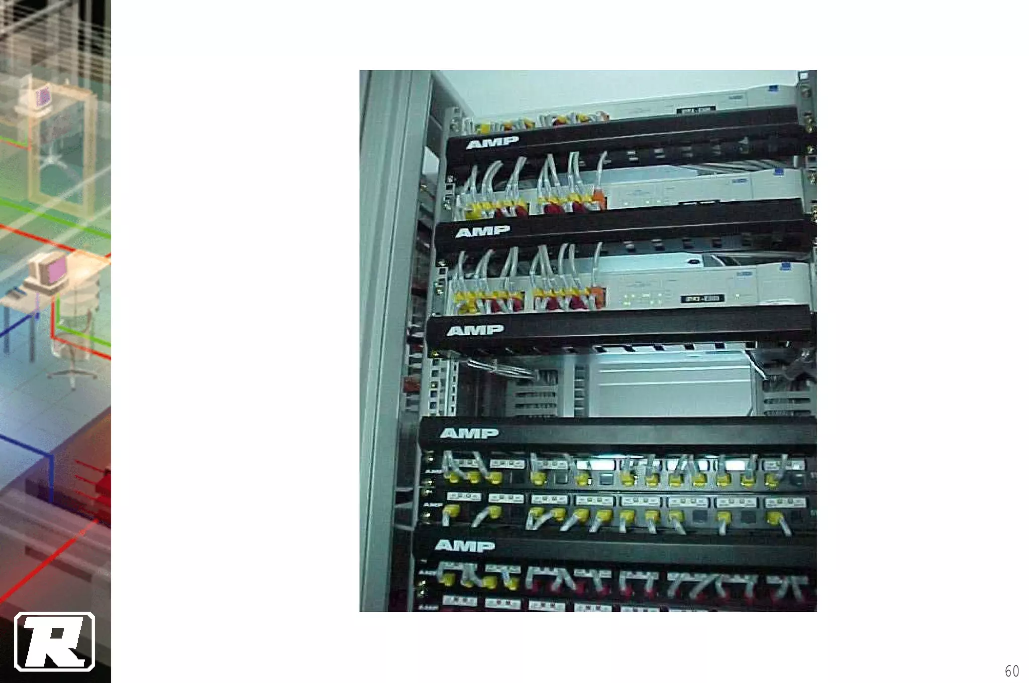
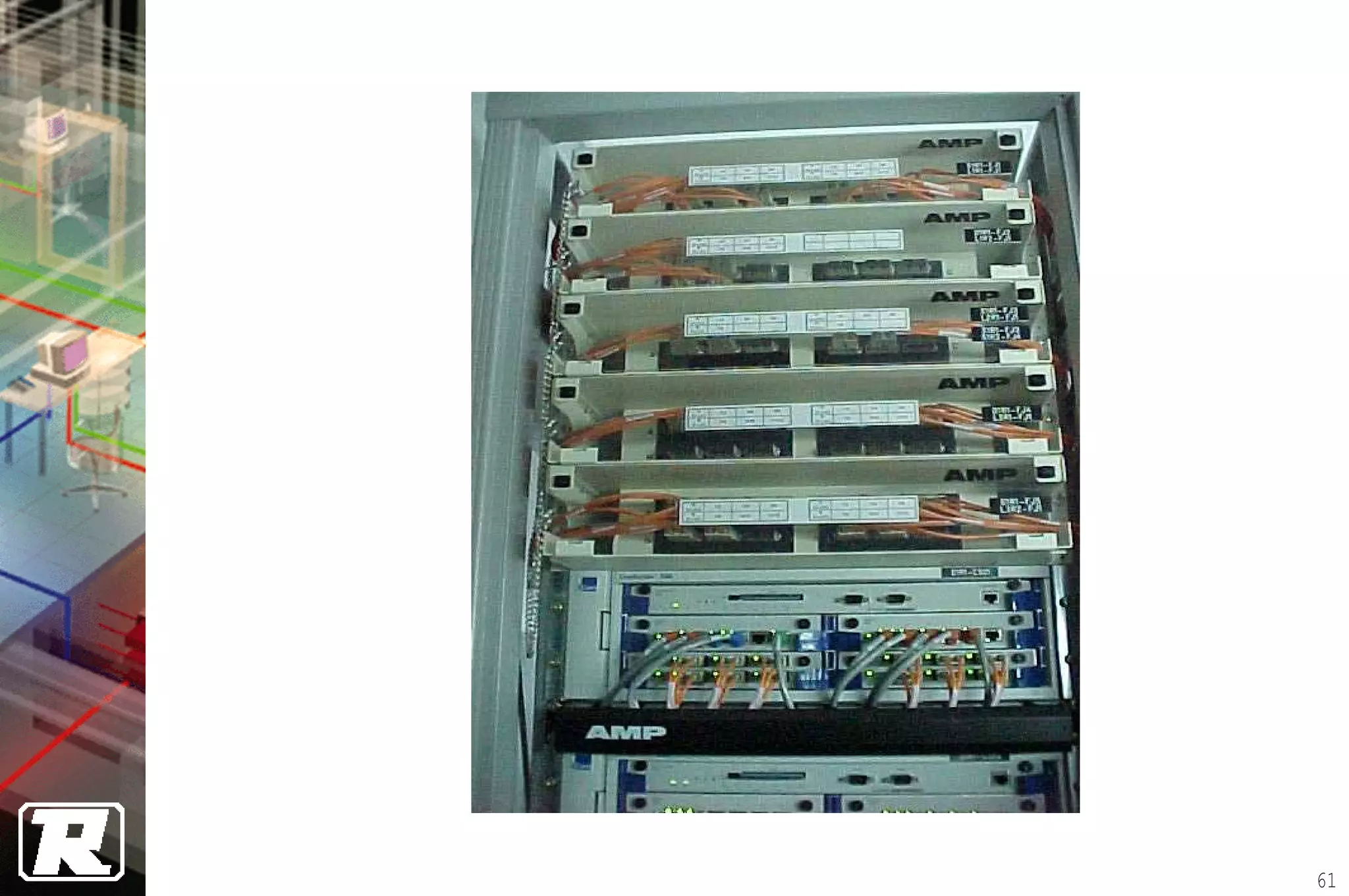
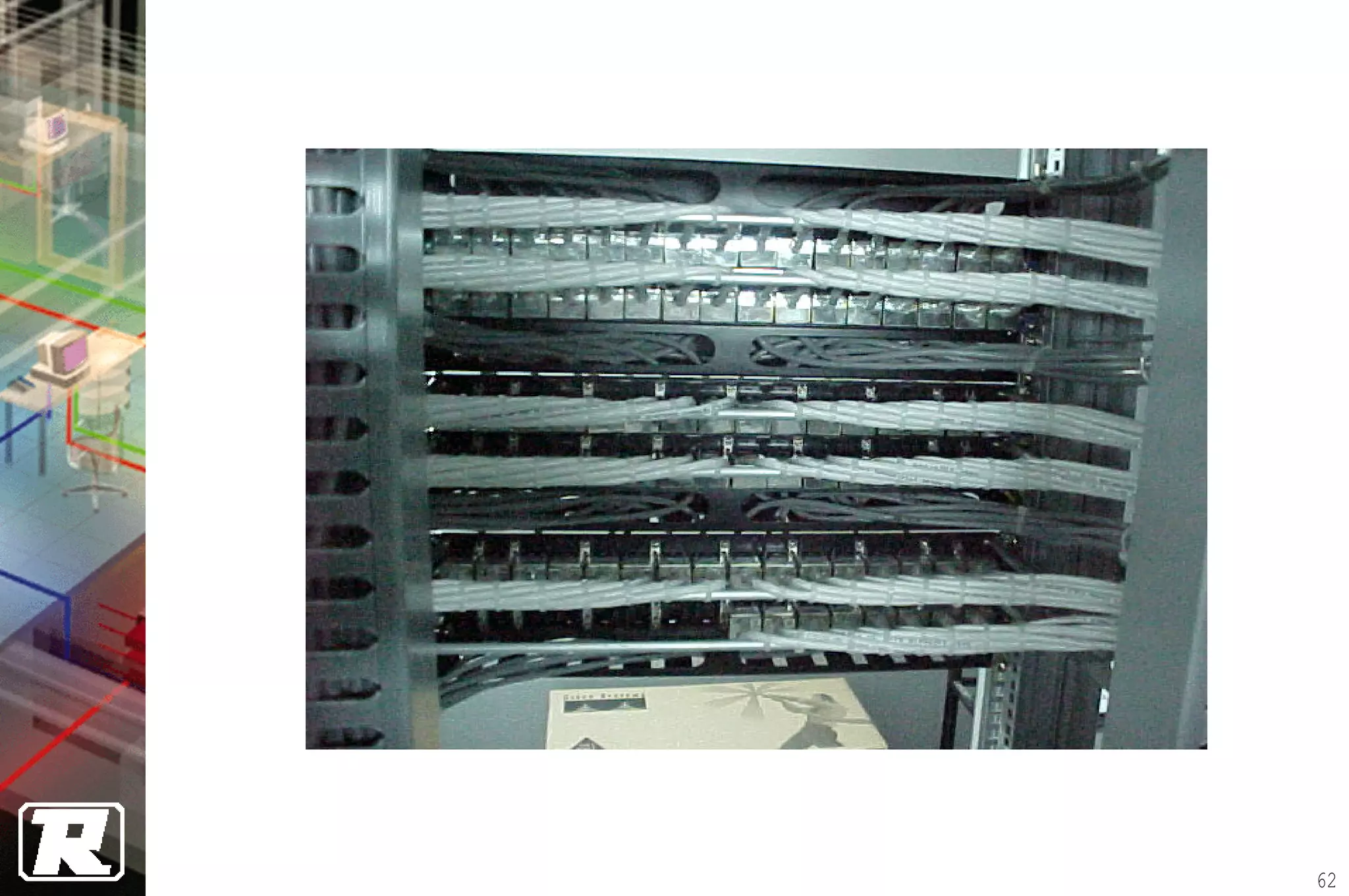
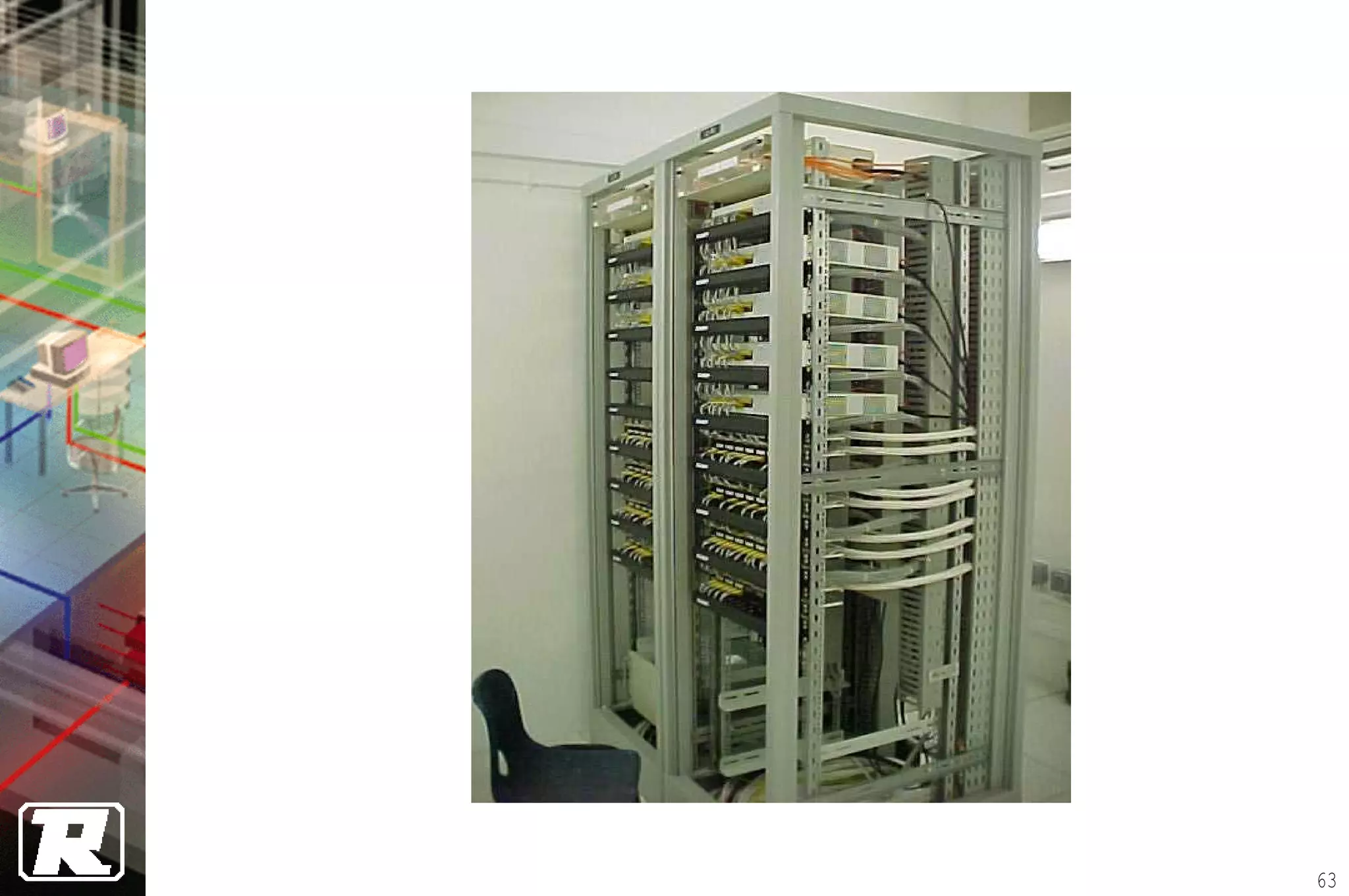
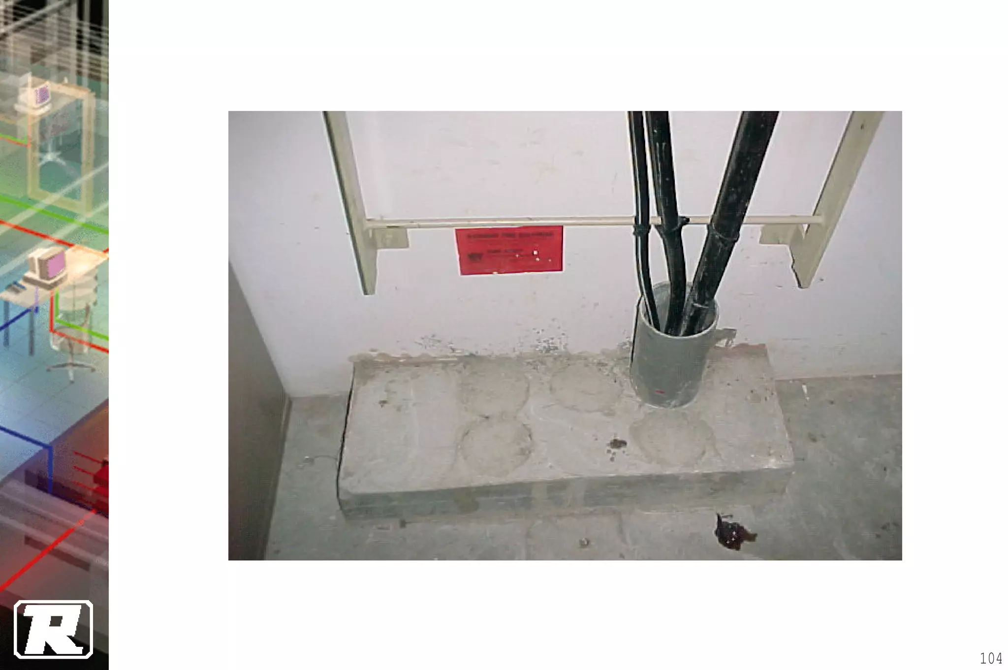
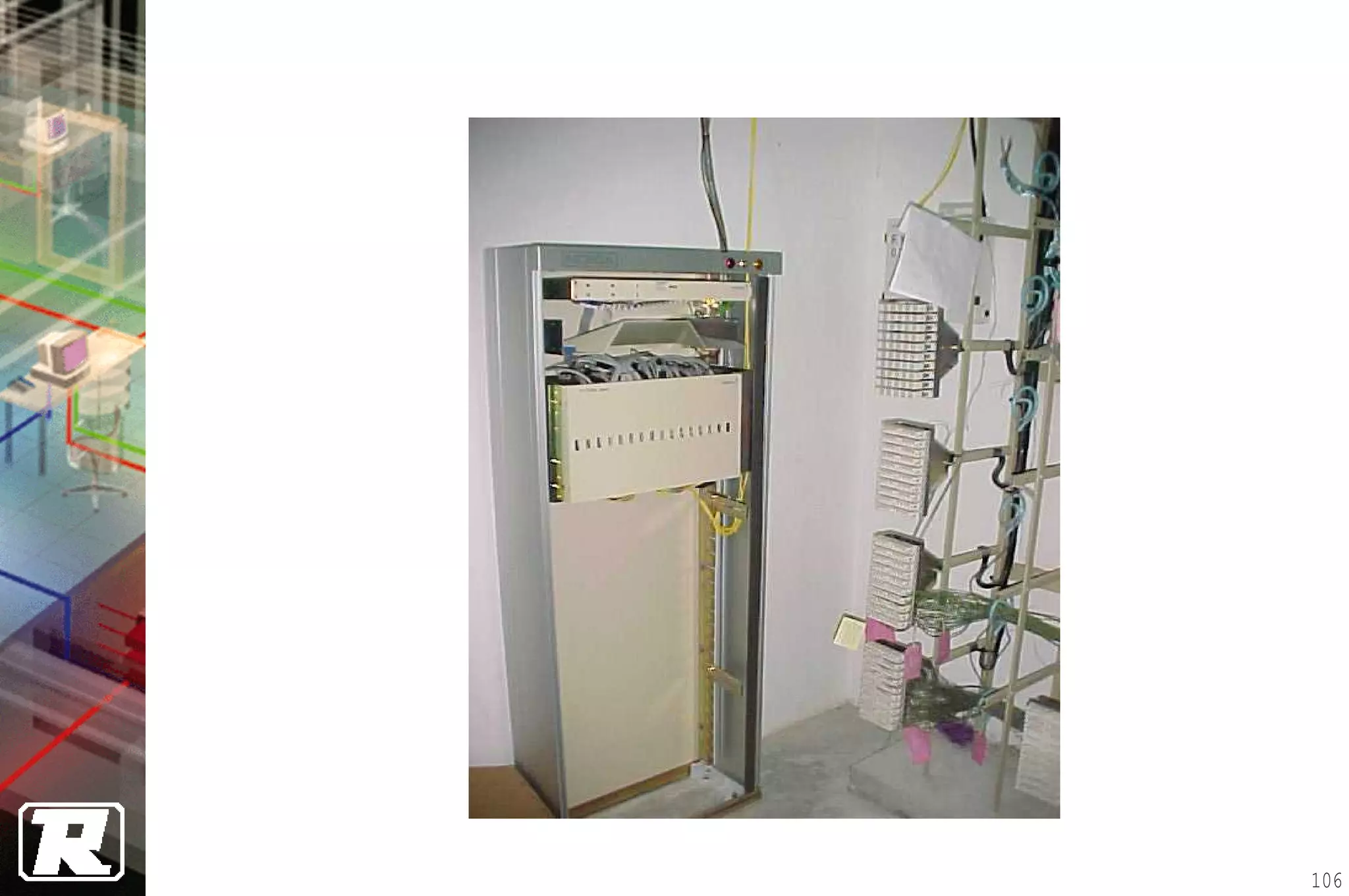
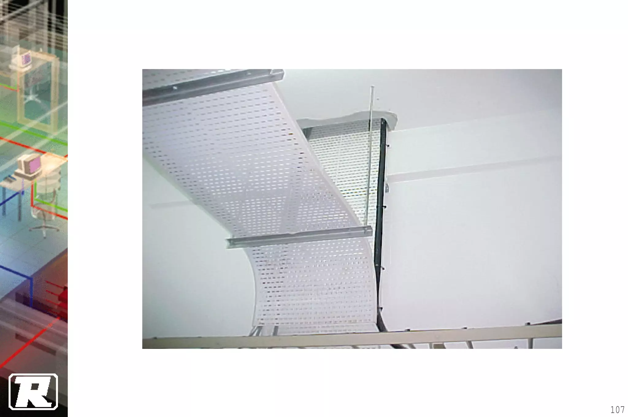
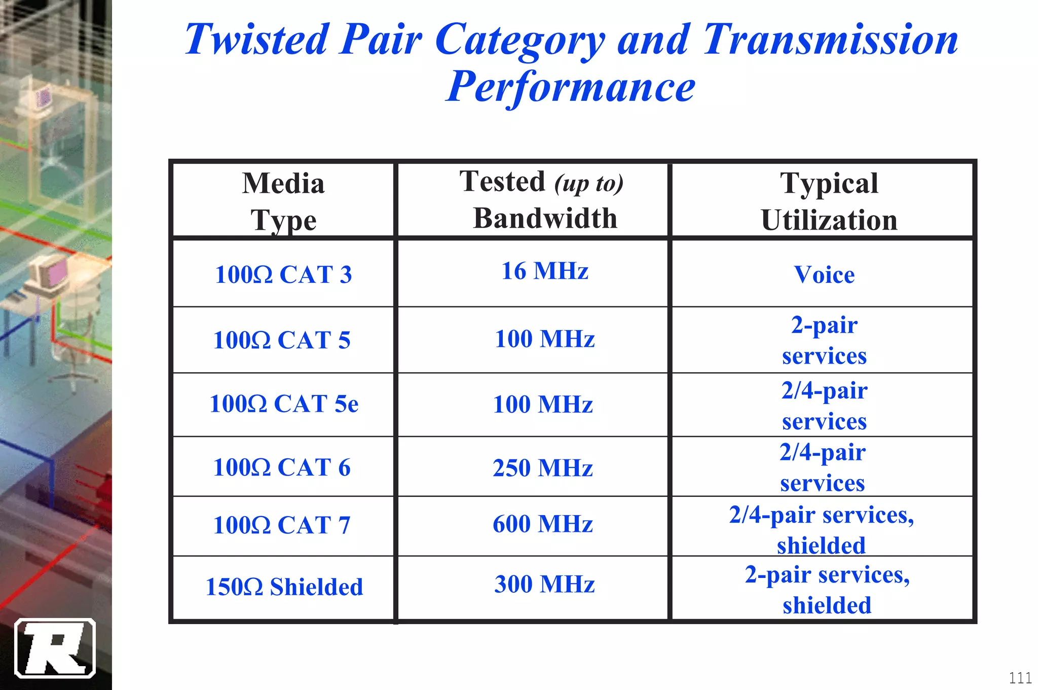
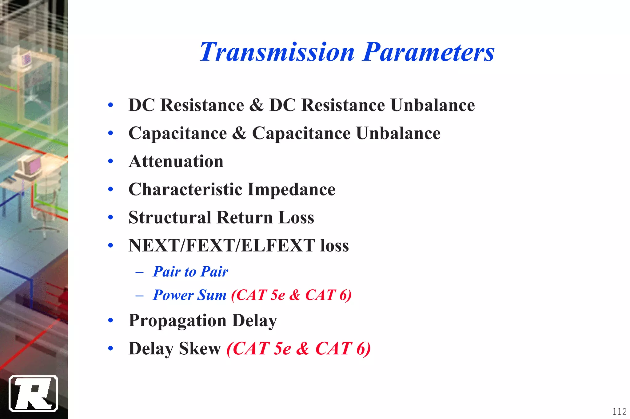
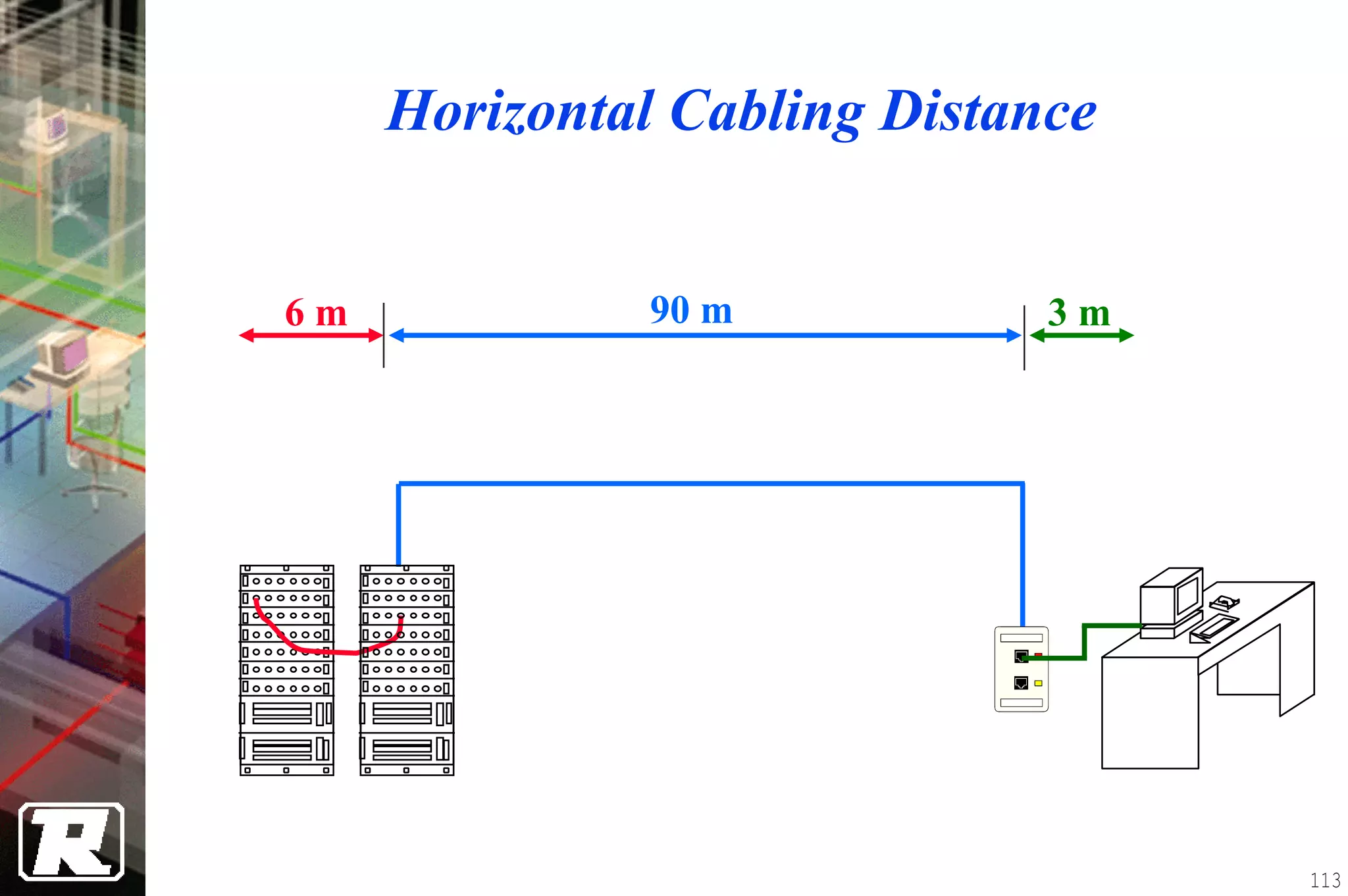
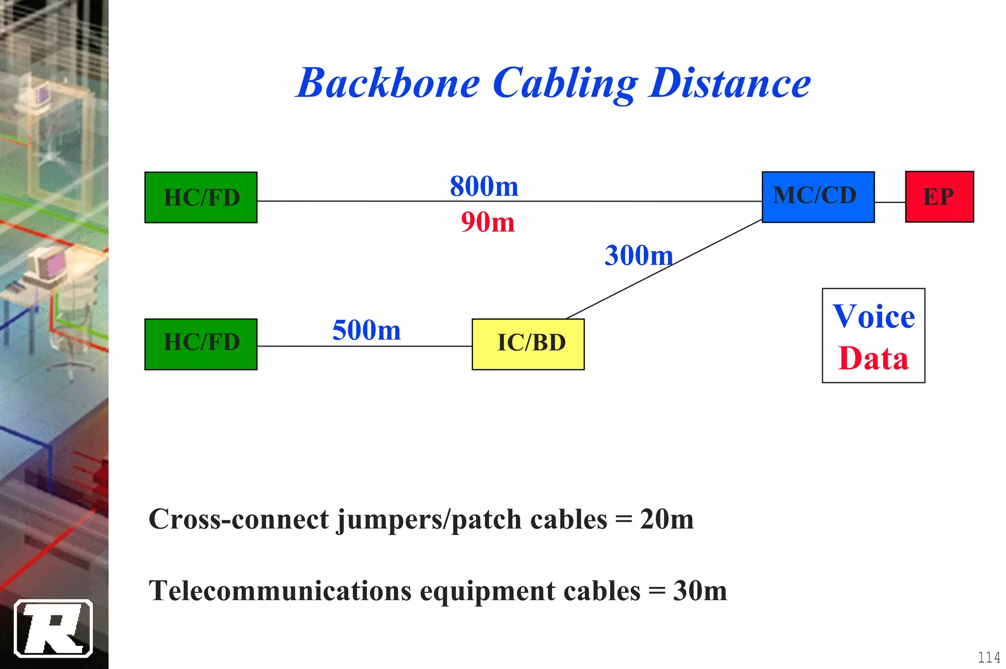
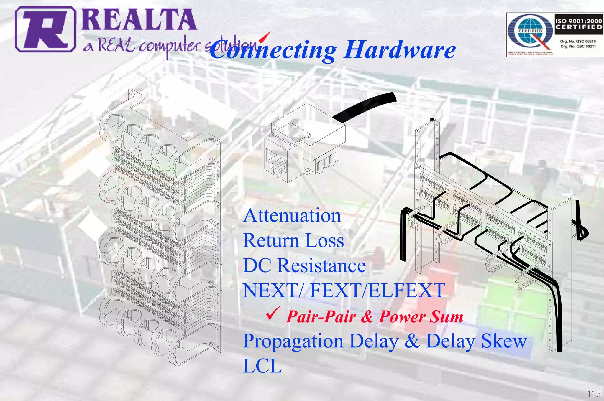
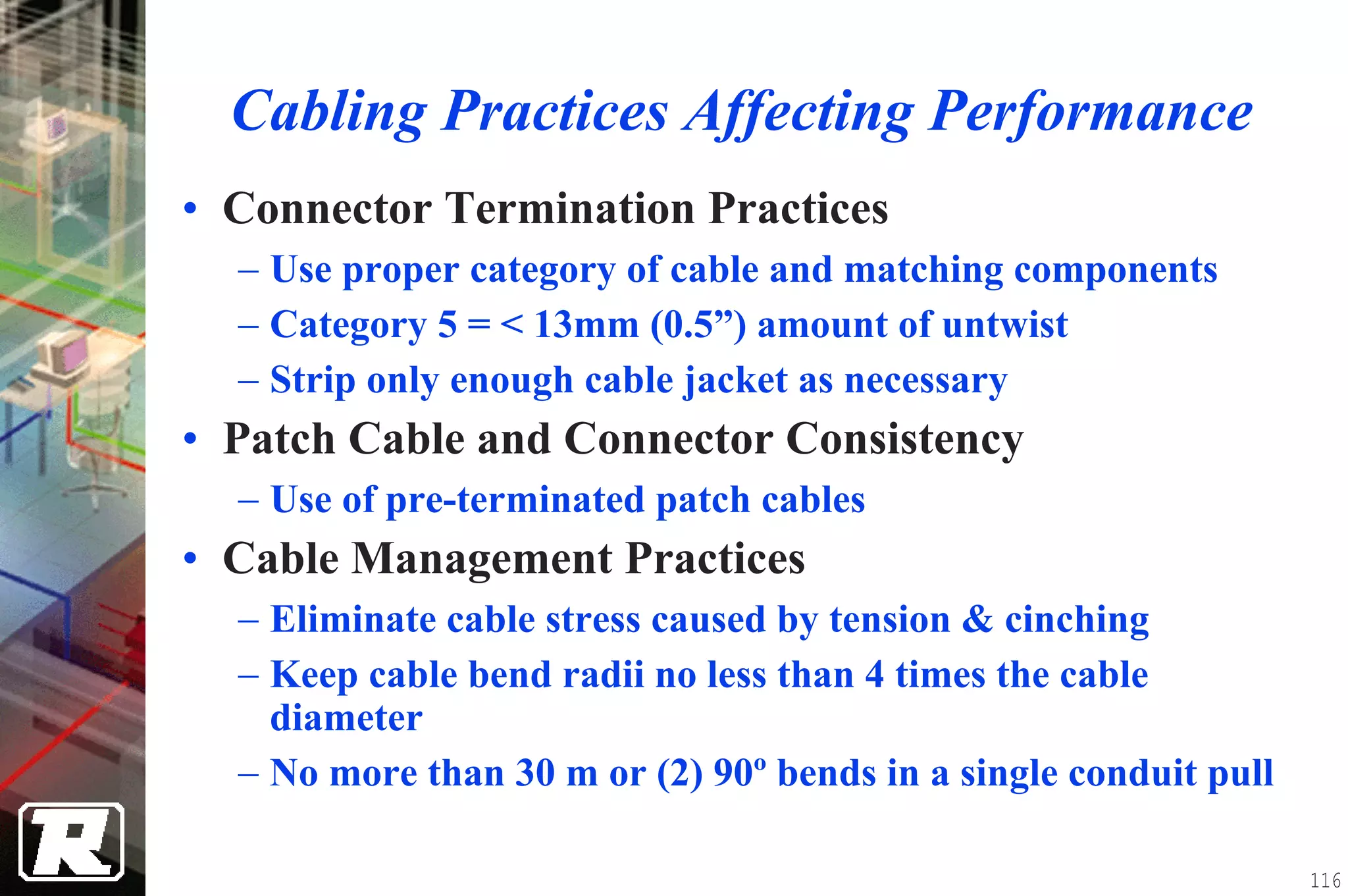
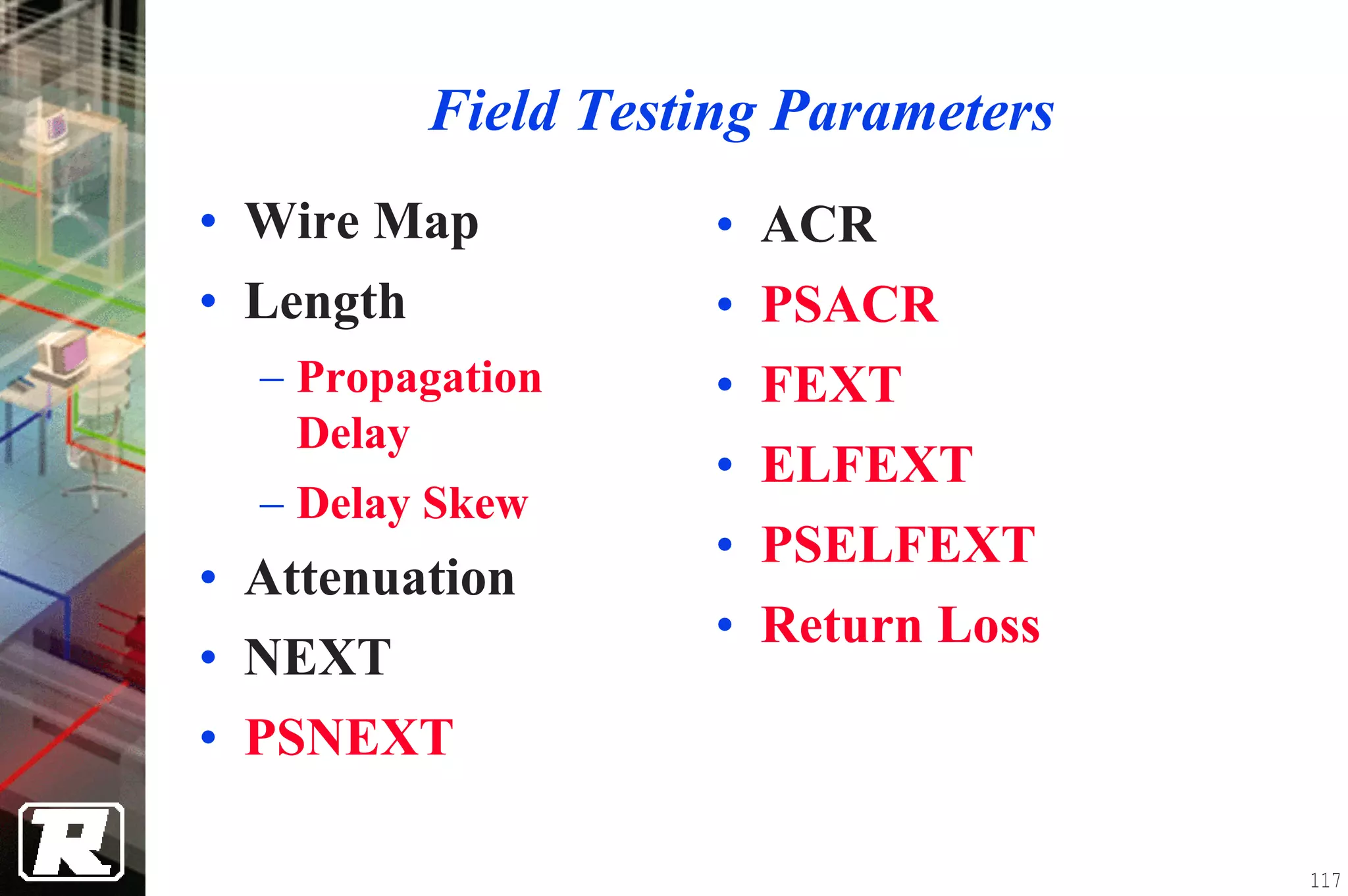
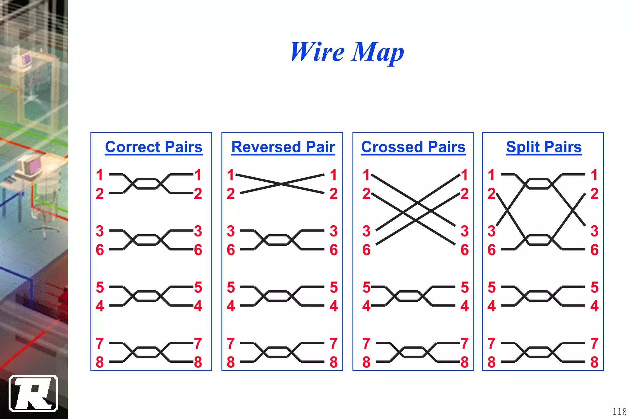
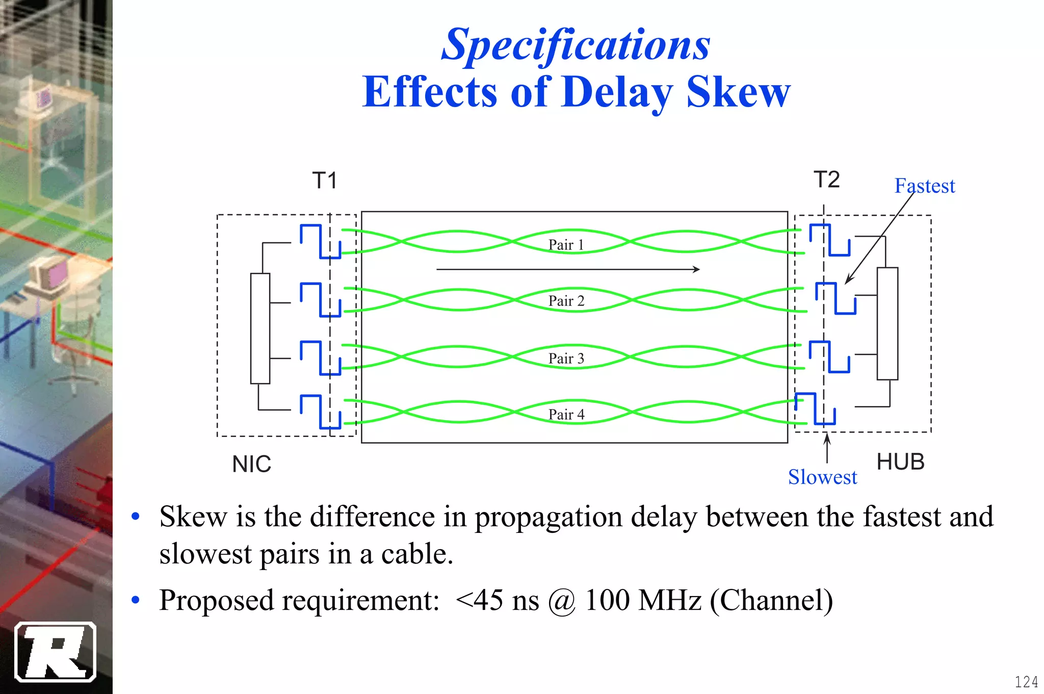
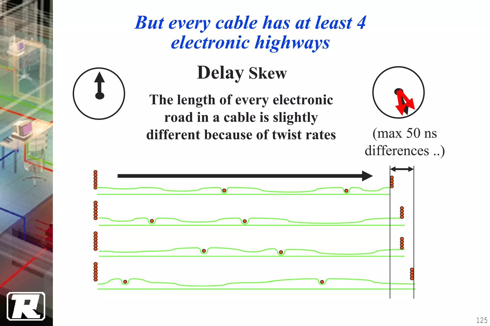
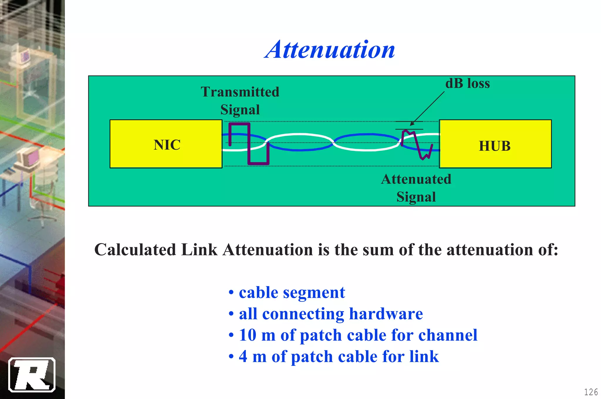
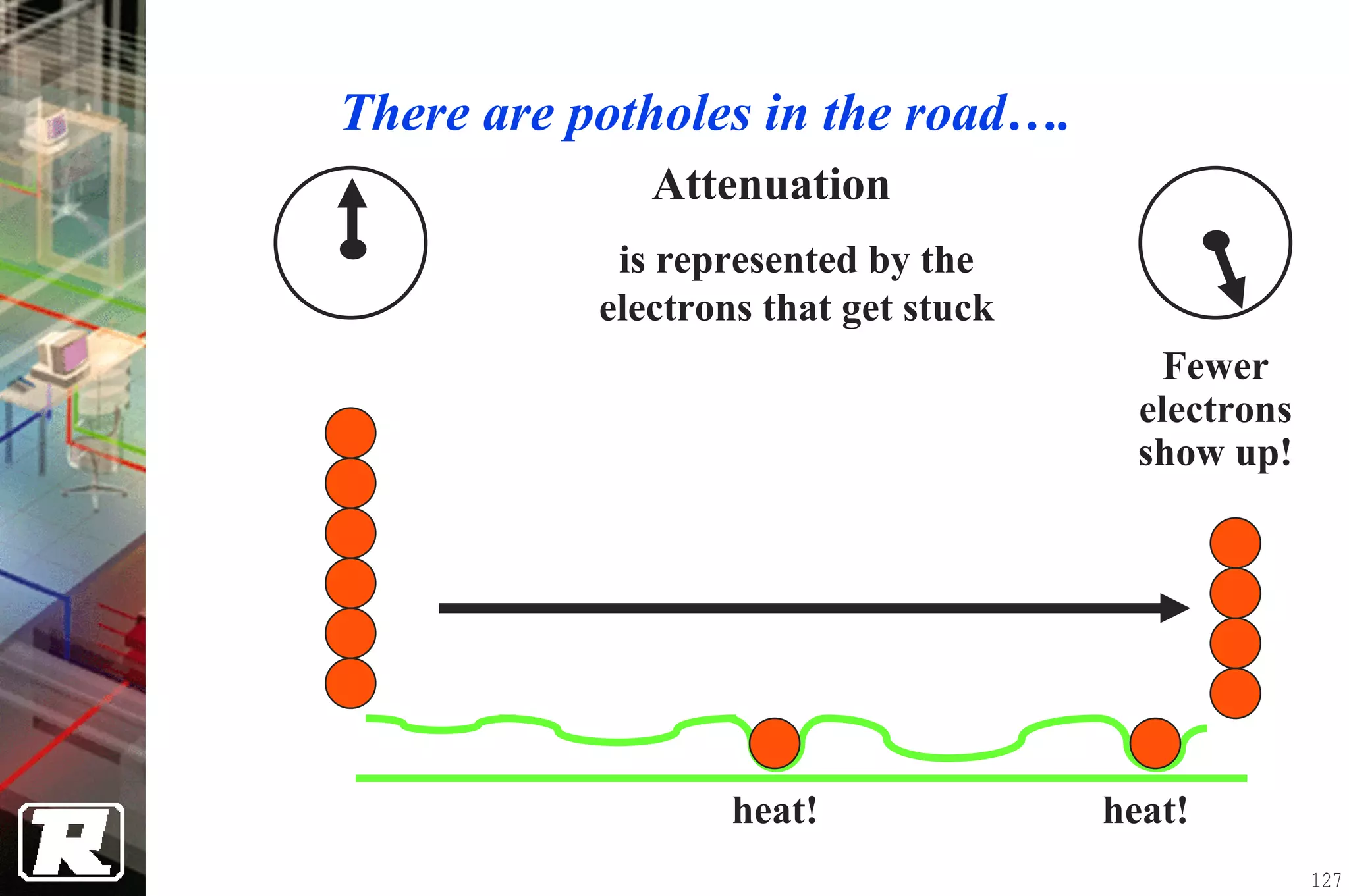
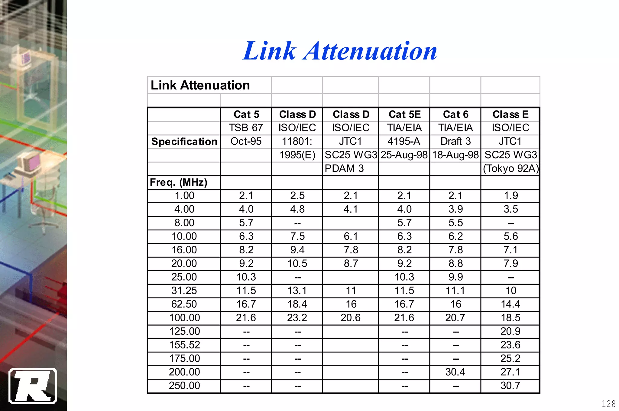
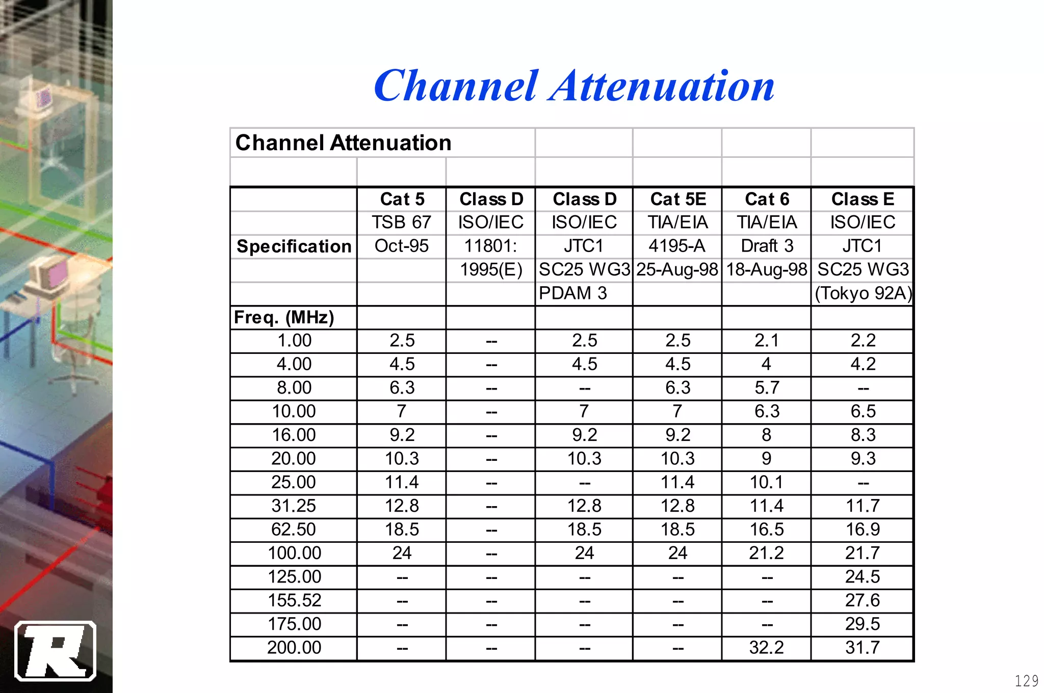
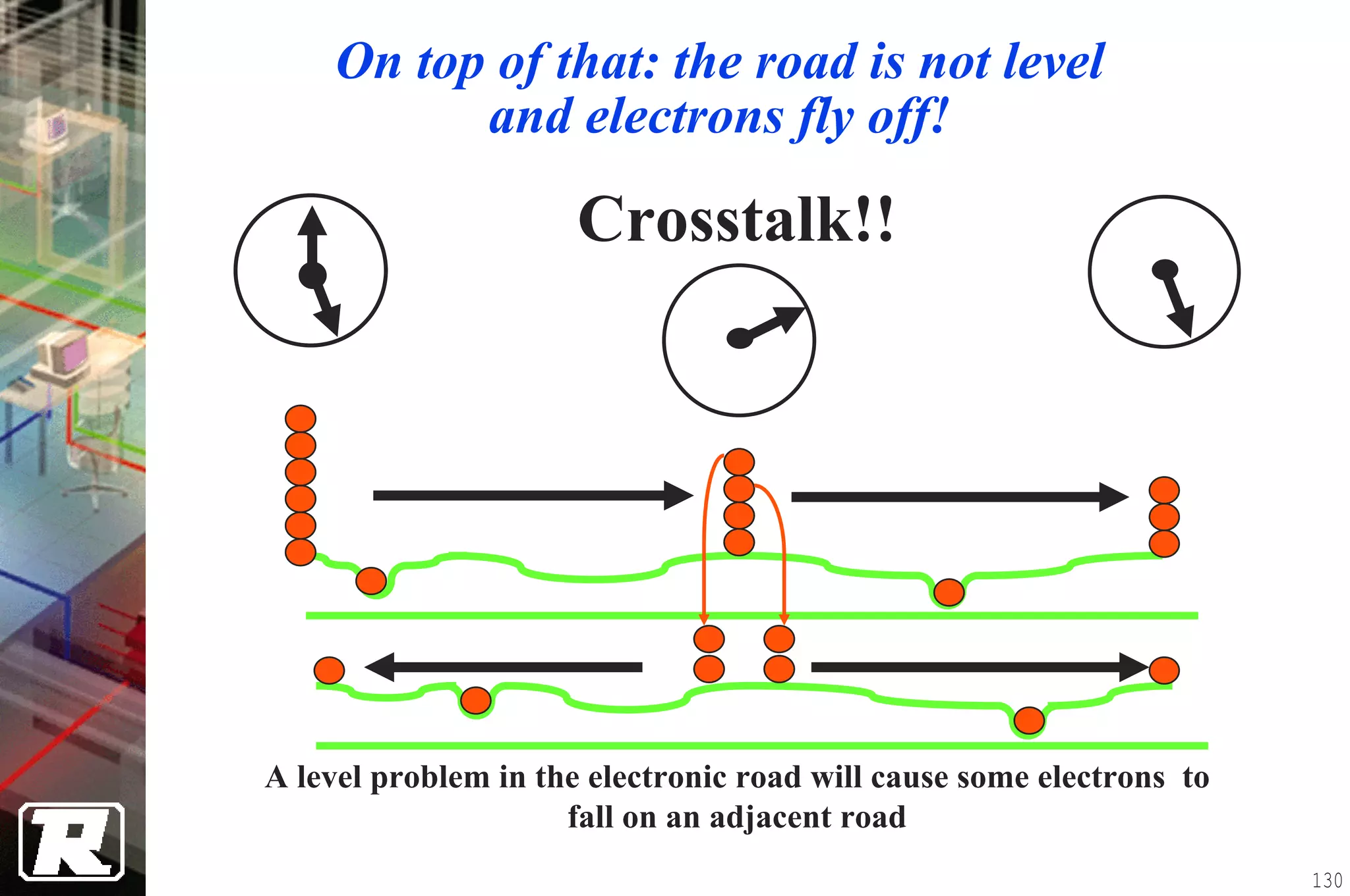
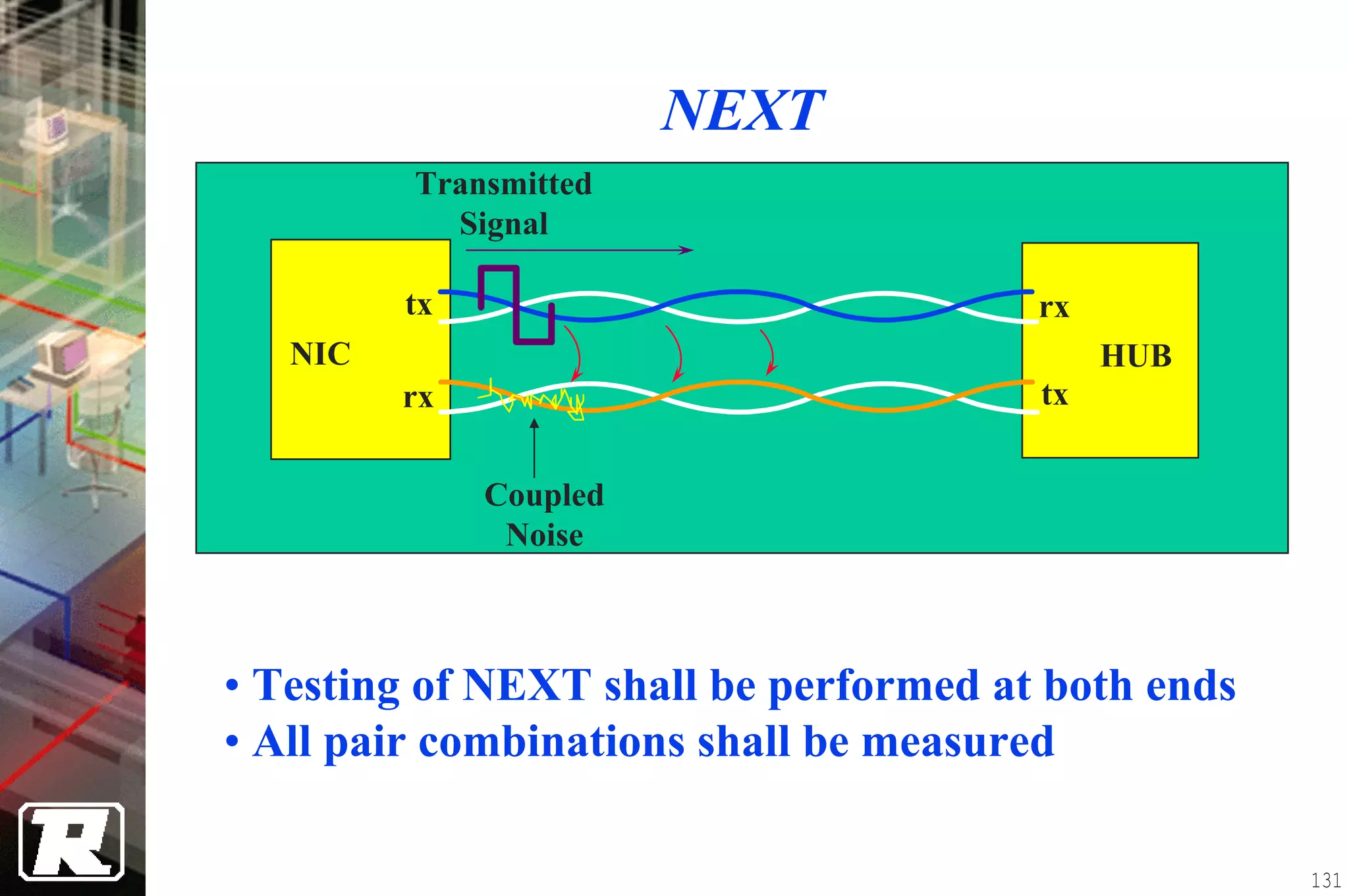
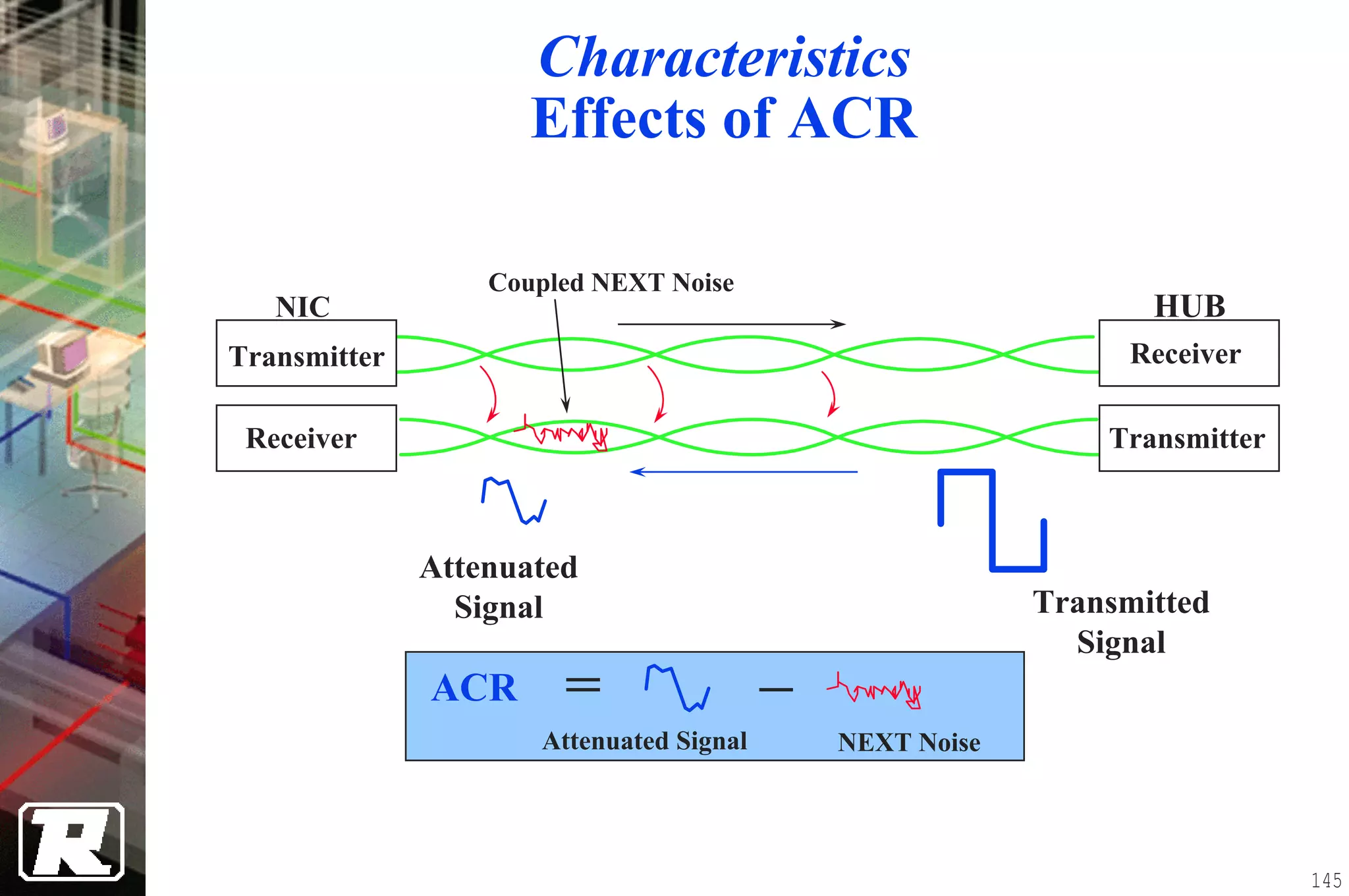
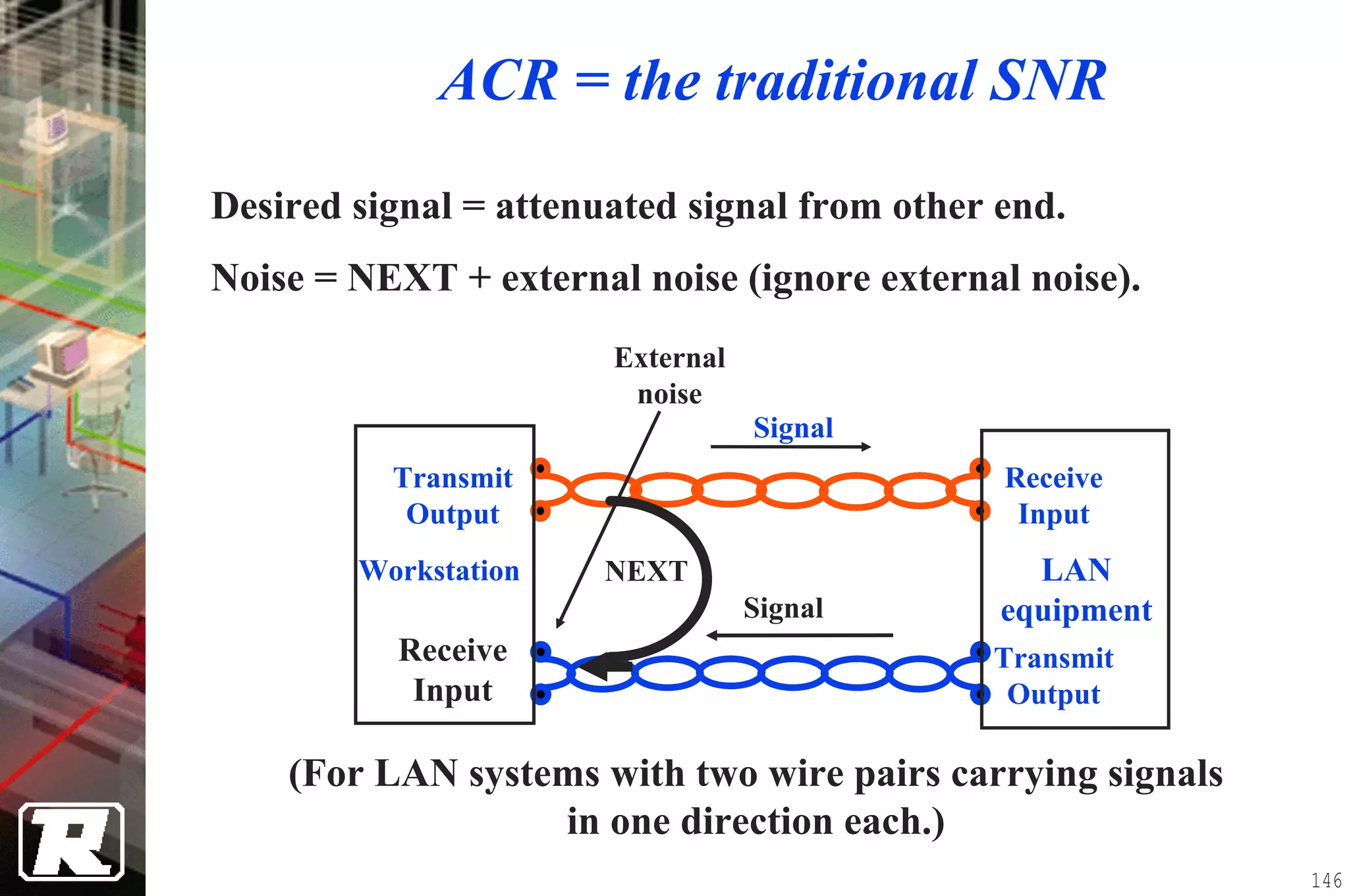
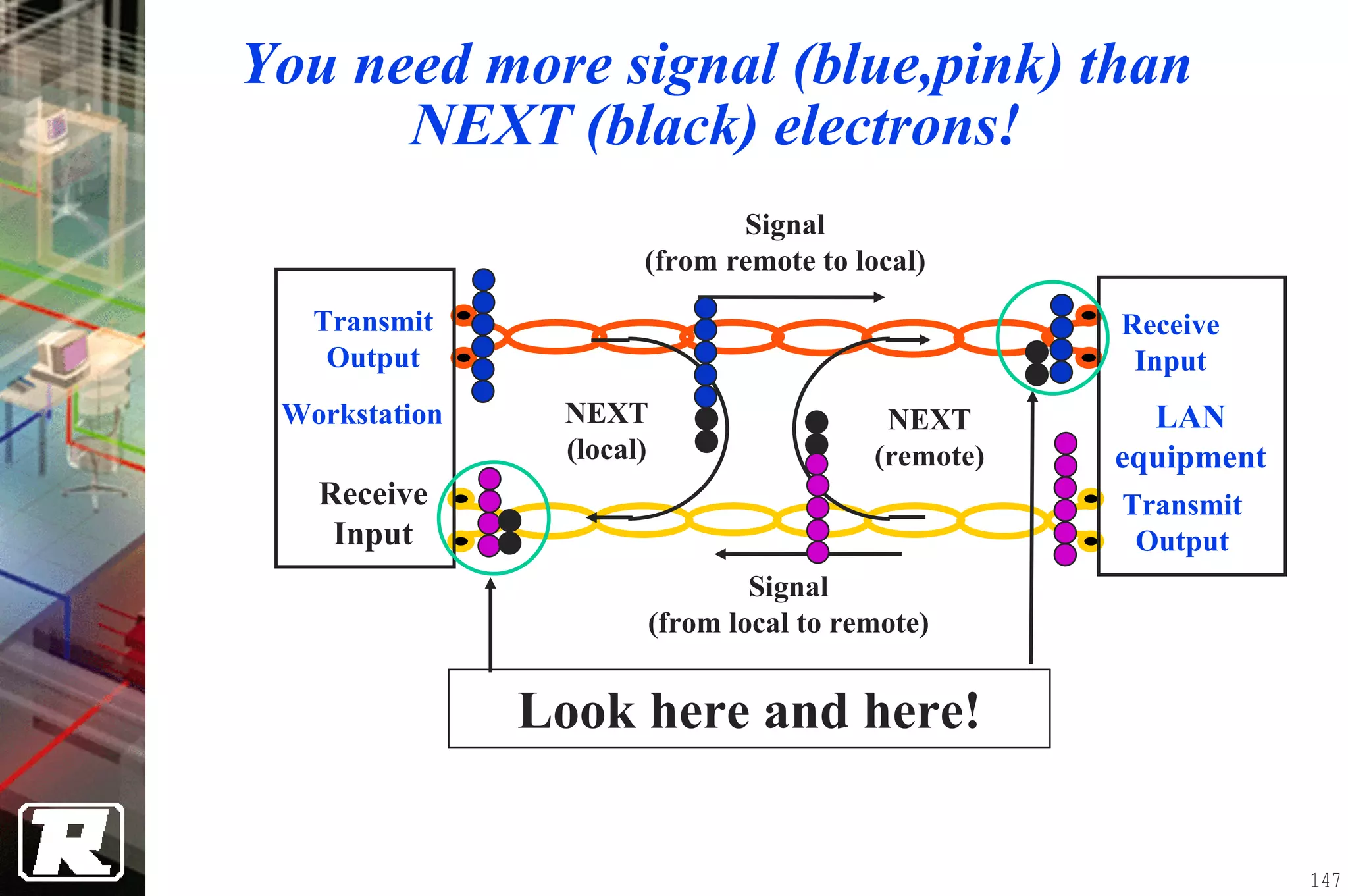
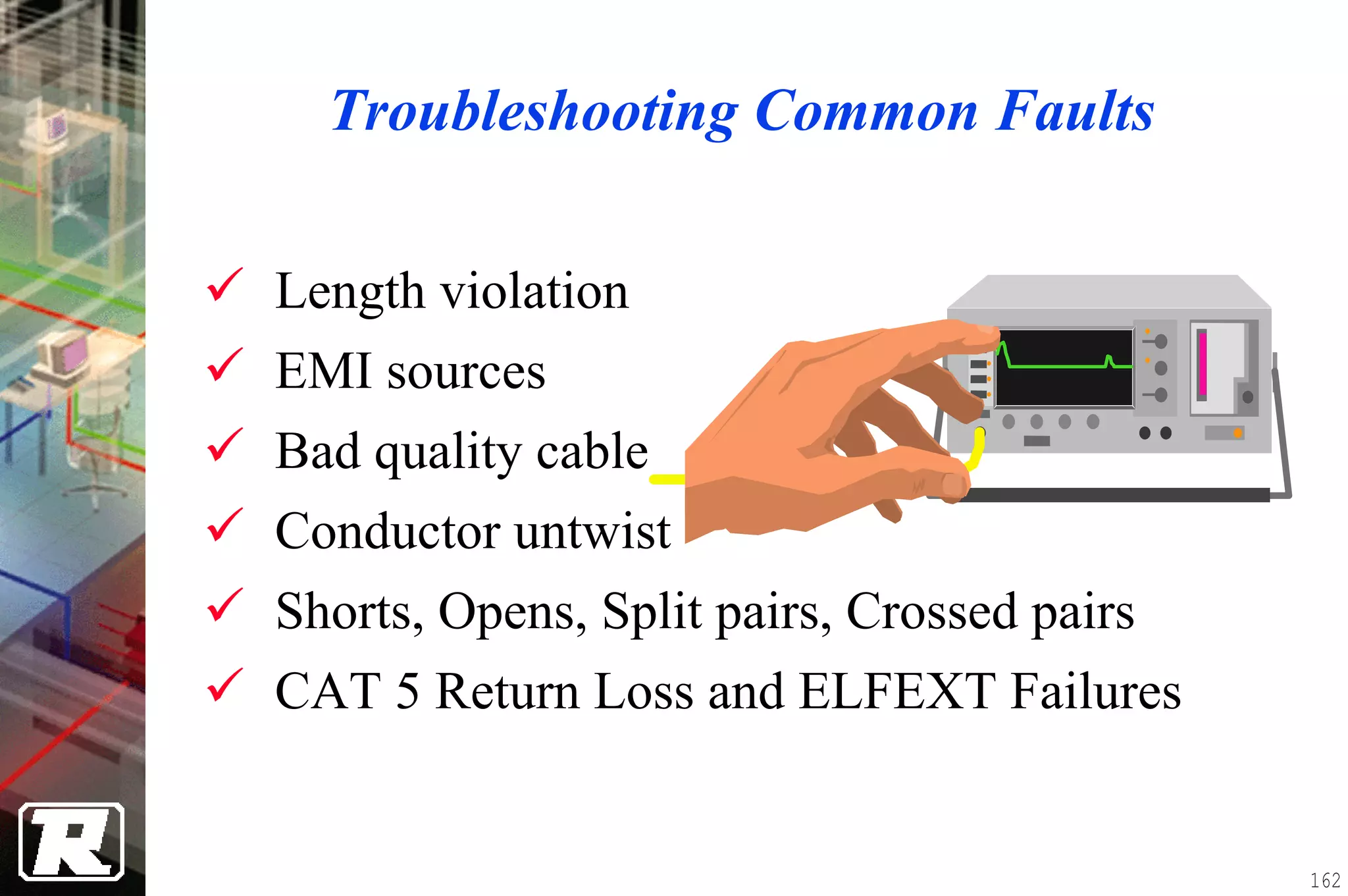
Basic Principal of
UTP INSTALLATION


                       1
Rough In


           2
Rough-in Items

• Installation Specification/Scope of Work
• Plans/Drawings
• Schedule/Bill of Materials
• Installation Tools
• Rough-in Materials


                                             3
Installation Specification
•   Standards and Specifications
•   Raceway capacity, placement and mounting
•   Horizontal routing and placement
•   Backbone routing and placement
•   Cross-connects and terminations
•   Cable Management
•   Labeling
•   Testing
• Documentation
                                               4
Floorplan Drawing


                    5
Outlet Elevation Drawing


                           6
Telecommunications Closet Elevation
            Drawing


                                      7
Rack Elevation Drawing


                         8
Bill of Materials

Mfg. #       Description       Qty U/M Cost         X-Cost

768597-2   4pr CAT 5, plenum   2600 L/ft    $0.39   $1014.00

            24 port, CAT 5
567409-1                        2    EA    $250.00 $500.00
             Patch Panel

              110, CAT 5       48
675675-9                             EA     $5.00   $240.00
             Universal Jack
237898-1   Zipcord M/M Fiber   2000 L/ft    $0.90   $1800.00

450989-1     SC Connector      60    EA    $7.50    $450.00


                                                               9
Wall Mount Outlet Box


                        10
Surface Mount Outlet Box


                           11
Raised/Access Floor Mount Box


                                12
Consolidation Point


                      13
Multi-User Outlet


                    14
Rack Spacing & Clearances


               32”/
               80cm

           Rear         Rear
                                 6”/
                                15cm
           Front        Front

        32”/
                         36”/
        80cm
                         1m

                   Live Equipment


                                       15
Rack Units (U’s)


  2U


   1U
 1.75”
(4.5cm)


  3U


                             16
Rack Attachment


                  17
Wall Mount Box


                 18
Rough In Photos


                  19
20
21
Over Hanging Cable Tray (Enclosed) #01


                                         22
Over Hanging Cable Tray (Enclosed) #02


  Cable Entry
  (From Outside)


                                         23
24
RISER - Vertical Cable Entry (Floor View)


                                            25
RISER - Vertical Cable Entry (Ceiling View)


                                              26
Telecommunication Closet Cable Entry


                                       27
28
29
30
31
32
33
34
35
36
37
38
39
40
41
42
43
44
45
46
47
48
49
50
51
52
53
54
55
56
57
58
59
60
61
62
63
64
65
66
67
68
69
70
71
Ceiling Grid #01


                   72
Cable Entry in User Room


  Cable Penetration Hole
     (View from Inside)


                           73
Cable Entry in User Room


   Cable Penetration Hole
      (View from Inside)


                            74
Perimeter Pathway


                Separator


                            75
Perimeter Pathway


                    76
Perimeter Pathway


  Electrical Outlet   Data Outlet Opening


                                            77
Perimeter Pathway


           Separation for Electrical and Data Cables


                                                       78
79
Underfloor Conduits


                      Cable Entry


                                    80
Underfloor Conduits


                      Cable Outlet


                                     81
82
83
84
85
86
87
Ceiling Grid #02


                   88
89
90
91
92
93
94
95
96
97
98
99
100
101
102
103
104
105
106
107
108
Twisted Pair
Cabling System


                 109
Twisted Pair Parameters

• Cable Category and Performance
• Cabling Distance
• Connector Performance
• System Performance
• Performance Testing


                                   110
Twisted Pair Category and Transmission
             Performance
   Media         Tested (up to)       Typical
   Type           Bandwidth          Utilization
 100Ω CAT 3         16 MHz              Voice
                                        2-pair
 100Ω CAT 5         100 MHz
                                       services
                                       2/4-pair
 100Ω CAT 5e       100 MHz
                                       services
                                       2/4-pair
 100Ω CAT 6        250 MHz
                                       services
 100Ω CAT 7        600 MHz        2/4-pair services,
                                      shielded
 150Ω Shielded      300 MHz        2-pair services,
                                       shielded

                                                       111
Transmission Parameters
• DC Resistance & DC Resistance Unbalance
• Capacitance & Capacitance Unbalance
• Attenuation
• Characteristic Impedance
• Structural Return Loss
• NEXT/FEXT/ELFEXT loss
   − Pair to Pair
   − Power Sum (CAT 5e & CAT 6)
• Propagation Delay
• Delay Skew (CAT 5e & CAT 6)


                                            112
Horizontal Cabling Distance


6m             90 m           3m


                                   113
Backbone Cabling Distance

 HC/FD                800m                  MC/CD      EP
                       90m
                                 300m

             500m                              Voice
 HC/FD                   IC/BD
                                               Data


Cross-connect jumpers/patch cables = 20m

Telecommunications equipment cables = 30m

                                                            114
Connecting Hardware


  Attenuation
  Return Loss
  DC Resistance
  NEXT/ FEXT/ELFEXT
      Pair-Pair & Power Sum
  Propagation Delay & Delay Skew
  LCL
                                   115
Cabling Practices Affecting Performance
• Connector Termination Practices
  − Use proper category of cable and matching components
  − Category 5 = < 13mm (0.5”) amount of untwist
  − Strip only enough cable jacket as necessary
• Patch Cable and Connector Consistency
  − Use of pre-terminated patch cables
• Cable Management Practices
  − Eliminate cable stress caused by tension & cinching
  − Keep cable bend radii no less than 4 times the cable
    diameter
  − No more than 30 m or (2) 90º bends in a single conduit pull

                                                                  116
Field Testing Parameters
• Wire Map            • ACR
• Length              • PSACR
  − Propagation       • FEXT
    Delay
                      • ELFEXT
  − Delay Skew
                      • PSELFEXT
• Attenuation
                      • Return Loss
• NEXT
• PSNEXT

                                      117
Wire Map


    Correct Pairs   Reversed Pair   Crossed Pairs       Split Pairs
1              1    1           1   1           1   1                 1
2              2    2           2   2           2   2                 2

3              3    3           3   3           3   3                 3
6              6    6           6   6           6   6                 6

5              5    5           5   5           5   5                 5
4              4    4           4   4           4   4                 4

7              7    7           7   7           7   7                 7
8              8    8           8   8           8   8                 8


                                                                          118
Length


• Maximum Link Length
  − 90 meters
    −   plus a maximum of 2 meters of test equipment
        patch cords at each end
• Maximum Channel Length
  − 100 meters
    −   including equipment cords and patch cords


                                                       119
Nominal Velocity of Propagation (NVP)


 The speed at which a signal travels in a cable,
 expressed as a percentage of the speed of light in
 vacuum.


          speed at which pulse travels in cable
 NVP =                                                X 100%
                 speed of light in vacuum
Speed of light in vacuum is 300,000 km/s or 0.3 m/nsec


                                                               120
Length Calculation

            RT_Prop_delay (nsec) x NVP x Speed_of_Light
Length =
                                         2
 Example:
   measurement of Prop_delay: 435 nsec

               NVP (%) Length (ft)
                 68.5     293.3
                 69       295.4
                 69.5     297.6
                 70       299.7
                                                          121
Propagation Delay and Delay Skew
                      Pair 1

                      Pair 2
  NIC                                       HUB
                      Pair 3

                      Pair 4


             Propagation Delay        Delay Skew
Frequency   Link        Channel   Link        Channel
 1 MHz      541 ns      580 ns    45 ns        50 ns
 2 MHz      531 ns      569 ns    45 ns       50 ns
 10 MHz     518 ns      555 ns    45 ns       50 ns
100 MHz     510 ns      548 ns    45 ns       50 ns
200 MHz     509 ns      547 ns    45 ns       50 ns
                                                        122
Traveling signals is like electrons
following a somewhat rocky path
         Propagation delay
        Electrons travel at approx.
              constant speed
          (≈ 20 cm or 8” per ns,      (max 555 ns
                                        later ..)
          1 ns = 0.000 000 0001 s
          NVP * speed of light)


                                                    123
Specifications
                   Effects of Delay Skew
              T1                                      T2       Fastest

                                 Pair 1


                                 Pair 2


                                 Pair 3


                                 Pair 4


        NIC                                                   HUB
                                                    Slowest
• Skew is the difference in propagation delay between the fastest and
  slowest pairs in a cable.
• Proposed requirement: <45 ns @ 100 MHz (Channel)

                                                                         124
But every cable has at least 4
    electronic highways
         Delay Skew
 The length of every electronic
    road in a cable is slightly
 different because of twist rates    (max 50 ns
                                    differences ..)


                                                      125
Attenuation
                                              dB loss
             Transmitted
               Signal

       NIC                                           HUB

                                     Attenuated
                                       Signal


Calculated Link Attenuation is the sum of the attenuation of:

                 • cable segment
                 • all connecting hardware
                 • 10 m of patch cable for channel
                 • 4 m of patch cable for link
                                                                126
There are potholes in the road….
              Attenuation
            is represented by the
           electrons that get stuck
                                         Fewer
                                        electrons
                                        show up!


                   heat!              heat!
                                                    127
Link Attenuation
Link Attenuation

                 Cat 5   Class D  Class D  Cat 5E     Cat 6     Class E
                TSB 67   ISO/IEC  ISO/IEC  TIA/EIA   TIA/EIA    ISO/IEC
Specification   Oct-95    11801:    JTC1   4195-A     Draft 3     JTC1
                         1995(E) SC25 WG3 25-Aug-98 18-Aug-98 SC25 WG3
                                 PDAM 3                       (Tokyo 92A)
Freq. (MHz)
     1.00         2.1      2.5       2.1       2.1      2.1       1.9
     4.00         4.0      4.8       4.1       4.0      3.9       3.5
     8.00         5.7       --                 5.7      5.5        --
    10.00         6.3      7.5       6.1       6.3      6.2       5.6
    16.00         8.2      9.4       7.8       8.2      7.8       7.1
    20.00         9.2     10.5       8.7       9.2      8.8       7.9
    25.00        10.3       --                10.3      9.9        --
    31.25        11.5     13.1       11       11.5     11.1       10
    62.50        16.7     18.4       16       16.7      16       14.4
   100.00        21.6     23.2      20.6      21.6     20.7      18.5
   125.00          --       --                  --       --      20.9
   155.52          --       --                  --       --      23.6
   175.00          --       --                  --       --      25.2
   200.00          --       --                  --     30.4      27.1
   250.00          --       --                  --       --      30.7
                                                                            128
Channel Attenuation
Channel Attenuation

                 Cat 5   Class D  Class D  Cat 5E     Cat 6     Class E
                TSB 67   ISO/IEC  ISO/IEC  TIA/EIA   TIA/EIA    ISO/IEC
Specification   Oct-95    11801:    JTC1   4195-A     Draft 3     JTC1
                         1995(E) SC25 WG3 25-Aug-98 18-Aug-98 SC25 WG3
                                 PDAM 3                       (Tokyo 92A)
Freq. (MHz)
     1.00         2.5      --        2.5       2.5      2.1       2.2
     4.00         4.5      --        4.5       4.5       4        4.2
     8.00         6.3      --         --       6.3      5.7        --
    10.00          7       --         7         7       6.3       6.5
    16.00         9.2      --        9.2       9.2       8        8.3
    20.00        10.3      --       10.3      10.3       9        9.3
    25.00        11.4      --         --      11.4     10.1        --
    31.25        12.8      --       12.8      12.8     11.4      11.7
    62.50        18.5      --       18.5      18.5     16.5      16.9
   100.00         24       --        24        24      21.2      21.7
   125.00          --      --         --        --       --      24.5
   155.52          --      --         --        --       --      27.6
   175.00          --      --         --        --       --      29.5
   200.00          --      --         --        --     32.2      31.7
                                                                            129
On top of that: the road is not level
           and electrons fly off!

                      Crosstalk!!


A level problem in the electronic road will cause some electrons to
                     fall on an adjacent road
                                                                      130
NEXT
         Transmitted
           Signal

         tx                            rx
   NIC                                      HUB
         rx                            tx


              Coupled
               Noise


• Testing of NEXT shall be performed at both ends
• All pair combinations shall be measured

                                                    131
Near End Crosstalk (NEXT)


Near End Crosstalk is by the electrons that return back
                  to the beginning
                                                          132
Link NEXT
Link NEXT

               Cat 5   Class D  Class D  Cat 5E     Cat 6     Class E
              TSB 67   ISO/IEC  ISO/IEC  TIA/EIA   TIA/EIA    ISO/IEC
Specification Oct-95    11801:    JTC1   4195-A     Draft 3     JTC1
                       1995(E) SC25 WG3 25-Aug-98 18-Aug-98 SC25 WG3
                                                            (Tokyo 92A)
Freq. (MHz)
     1.00       60      54.0      61.2      64.2     73.5       72.7
     4.00      51.8     45.0      51.8      54.8     64.1        63
     8.00      47.1      --        --       50.0     59.4        --
    10.00      45.5     39.0      45.5      48.5     57.8       56.6
    16.00      42.3     36.0      42.3      45.2     54.6       53.2
    20.00      40.7     35.0      40.7      43.7     53.1       51.6
    25.00      39.1      --        --       42.1     51.5        --
    31.25      37.6     32.0      37.6      40.6      50        48.4
    62.50      32.7     27.0      32.7      35.7     45.2       43.4
   100.00      29.3     24.0      29.3      32.3     41.9       39.9
   125.00       --       --        --        --       --        38.3
   155.52       --       --        --        --       --        36.7
   175.00       --       --        --        --       --        35.8
   200.00       --       --        --        --      36.9       34.8
   250.00       --       --        --        --       --        33.1
                                                                          133
Channel NEXT
Channel NEXT

               Cat 5   Class D  Class D  Cat 5E     Cat 6     Class E
              TSB 67   ISO/IEC  ISO/IEC  TIA/EIA   TIA/EIA    ISO/IEC
Specification Oct-95    11801:    JTC1   4195-A     Draft 3     JTC1
                       1995(E) SC25 WG3 25-Aug-98 18-Aug-98 SC25 WG3
                                                            (Tokyo 92A)
Freq. (MHz)
    1.00       60.0      --       60.3      63.3     72.7       72.7
    4.00       50.6      --       50.6      53.6     63.1        63
    8.00       45.6      --        --       48.6     58.2        --
   10.00       44.0      --        44       47.0     56.6       56.6
   16.00       40.6      --       40.6      43.6     53.2       53.2
   20.00       39.0      --        39       42.0     51.6       51.6
   25.00       37.4      --        --       40.4      50         --
   31.25       35.7      --       35.7      38.7     48.4       48.4
   62.50       30.6      --       30.6      33.6     43.4       43.4
   100.00      27.1      --       27.1      30.1     39.9       39.9
   125.00       --       --        --        --       --        38.3
   155.52       --       --        --        --       --        36.7
   175.00       --       --        --        --       --        35.8
   200.00       --       --        --        --      34.8       34.8
   250.00       --       --        --        --       --        33.1
                                                                          134
FEXT
         Transmitted
           Signal           Attenuated
                              Signal
         tx                              rx
   NIC                                        HUB
         rx                              tx

                               Coupled
                                Noise


• Testing of FEXT shall be performed at both ends
• All pair combinations shall be measured

                                                    135
Far end crosstalk (FEXT)


Far End Crosstalk is by the electrons that continue
                 to the far end
                                                      136
Return Loss

 -12dBm tx                               rx   -14dBm


• Typically attenuation caused by characteristics
  inherent in the cable, such as:

               • impedance mismatches
               • kinks in the cable
               • poor construction


                                                       137
Specifications
                       Effects of Return Loss
                               Reflected Signals
         Transmitted Signals                                  Attenuated Signals


                                        Pair 1


                                        Pair 2


                                        Pair 3


                                        Pair 4


          NIC                            Impedance mismatch           HUB
                                             or variation
• A measure of the reflected transmit energy caused by impedance mismatches in
  the cabling systems
• Especially important in applications that use full duplex transmission schemes


                                                                                   138
There are also bumps and dips
   in the road: return loss


                                A bump or dip
                                    causes
                                some electrons
                                  to go back


                                                 139
Link Return Loss
Link Return Loss

               Cat 5   Class D      Class D    Cat 5E   Cat 6     Class E
              TSB 67   ISO/IEC      ISO/IEC    TIA/EIA TIA/EIA    ISO/IEC
Specification Oct-95    11801:        JTC1     4195-A  Draft 3      JTC1
                       1995(E)    SC25 WG3 25-Aug-98 18-Aug-98 SC25 WG3
                                 (Orlando 39A)                 (Orlando 39A)
Freq. (MHz)
    1.00        --      18.0        17.0       17.0      19.0       19.0
    4.00        --      18.0        17.0       17.0      19.0       19.0
    8.00        --      18.0        17.0       17.0      19.0       19.0
    10.00       --      15.0        17.0       17.0      19.0       19.0
    16.00       --      15.0        17.0       17.0      19.0       19.0
    20.00       --      15.0        17.0       17.0      19.0       19.0
    25.00       --      10.0        16.3       16.3      18.3       18.3
    31.25       --      10.0        15.6       15.6      17.6       17.6
    62.50       --      10.0        13.5       13.5      15.5       15.5
   100.00       --      10.0        12.1       12.1      14.1       14.1
   125.00       --       --          --         --       13.4       13.4
   155.52       --       --          --         --       12.8       12.8
   175.00       --       --          --         --       12.4       12.4
   200.00       --       --          --         --        12         12
   250.00       --       --          --         --       11.3       11.3
                                                                               140
Channel Return Loss
Channel Return Loss

               Cat 5   Class D      Class D    Cat 5E   Cat 6     Class E
              TSB 67   ISO/IEC      ISO/IEC    TIA/EIA TIA/EIA    ISO/IEC
Specification Oct-95    11801:        JTC1     4195-A  Draft 3      JTC1
                       1995(E)    SC25 WG3 25-Aug-98 18-Aug-98 SC25 WG3
                                 (Orlando 39A)                 (Orlando 39A)
Freq. (MHz)
    1.00        --       --          17         17        19         19
    4.00        --       --          17         17        19         19
    8.00        --       --          17         17        19         19
    10.00       --       --          17         17        19         19
    16.00       --       --          17         17        19         19
    20.00       --       --          17         17        19         19
    25.00       --       --          16         16        18         18
    31.25       --       --         15.1       15.1      17.1       17.1
    62.50       --       --         12.1       12.1      14.1       14.1
   100.00       --       --          10         10        12         12
   125.00       --       --          --         --        11         11
   155.52       --       --          --         --       10.1       10.1
   175.00       --       --          --         --        9.6       9.6
   200.00       --       --          --         --         9          9
   250.00       --       --          --         --         8          8

                                                                               141
Some electrons may fly into the air and
      eventually land on earth!

           Electromagnetic
         Interference (EMI)!!


Electrons in the air may be picked up by your radio or TV antenna
                      and cause interference!
                                                                    142
Signal-to-noise ratios (3)


• There are three quantities which affect
  signal-to-noise ratio (SNR):
• Attenuation to Crosstalk Ratio (ACR).
• Equal Level Far End Crosstalk
  (ELFEXT).
• Return Loss.


                                            143
Signal-to-noise ratio #1: ACR

• Attenuation to Crosstalk Ratio (ACR)
• Applicable to 2-wire pair LAN
  applications (10BASE-T, 100BASE-
  TX).
• Each wire pair carries signal in one
  direction only.


                                         144
Characteristics
                     Effects of ACR

                  Coupled NEXT Noise
   NIC
   NIC                                                       HUB
                                                             Hub
Transmitter                                                 Receiver

 Receiver                                                 Transmitter


              Attenuated
                Signal                                Transmitted
                                                        Signal
              ACR
                     Attenuated Signal   NEXT Noise


                                                                        145
ACR = the traditional SNR
Desired signal = attenuated signal from other end.
Noise = NEXT + external noise (ignore external noise).
                       External
                        noise
                                  Signal
          Transmit                            Receive
           Output                              Input
        Workstation    NEXT                     LAN
                                  Signal      equipment
          Receive                            Transmit
           Input                              Output

    (For LAN systems with two wire pairs carrying signals
                  in one direction each.)
                                                            146
You need more signal (blue,pink) than
      NEXT (black) electrons!
                             Signal
                      (from remote to local)

   Transmit                                       Receive
    Output                                         Input
 Workstation    NEXT                    NEXT        LAN
                (local)                (remote)   equipment
   Receive                                        Transmit
    Input                                          Output
                              Signal
                      (from local to remote)


               Look here and here!

                                                              147
Signal-to-noise ratio (ELFEXT)

• Equal Level Far End Crosstalk
  (ELFEXT).
• Applicable to applications where 2 or
  more signals travel in the same
  direction at the same time (1000BASE-
  T).


                                          148
Another S/N = ELFEXT
Desired signal = attenuated signal from other end.
Noise = FEXT + external noise (ignore external noise).
                                 External
                                  noise
                               Signal
          Transmit                            Receive
           Output                              Input
                               FEXT
        Workstation                             LAN
                                 Signal       equipment
          Transmit                             Receive
           Output
                                                Input

   (For LAN systems with two or more wire pairs carrying
       signals in the same direction at the same time.)
                                                           149
You need more signal (blue,pink) than
      FEXT (black) electrons!
                          Signal
                  (from local to remote)
   Transmit                                   Receive
    Output                                     Input
               FEXT
 Workstation                                    LAN
               FEXT                           equipment
  Transmit
   Output                                      Receive
                                                Input
                          Signal
                (also from local to remote)


                 Look here!


                                                          150
Yet another S/N = Return Loss
Desired signal = attenuated signal from other end.
Noise = reflected signal in own wire pair

                “hybrid”                      “hybrid”
                                Signal

  Transmit                                               Transmit
   Output                                                 Output
  Workstation                                              LAN
                             Return loss
                               (bump in                  equipment
   Receive                 electronic road)              Receive
    Input                                                 Input

 (For LAN systems with a wire pair carrying signals in both
               directions at the same time.)
                                                                     151
Yet another S/N = Return Loss
Desired signal = attenuated signal from other end.
Noise = reflected signal from own end

                “hybrid”                                 “hybrid”

                           Signal          Signal
  Transmit                                                          Transmit
   Output                                                            Output
  Workstation                                                         LAN
                                                                    equipment
   Receive                                                          Receive
    Input                  Return loss signal (bump in               Input
                                electronic road)
 (For LAN systems with a wire pair carrying signals in both
               directions at the same time.)
                                                                                152
Power Sum Performance


Pair-to-pair:           Power sum:
Single disturber        Multiple disturbers
Single receiver         Single receiver


• Power sum performance is the sum of the pair-to-pair
  performance of the component or system.
• Power sum NEXT performance should meet or exceed the
  existing TIA pair-to-pair NEXT requirements.

                                                         153
What is “power sum” NEXT and
         “power sum” ELFEXT?

• Both are computed values from measured pair to
  pair NEXT or ELFEXT results:
  − Power Sum NEXT computed from three
    pair-to-pair NEXT results
  − Power Sum ELFEXT is computed from
    three pair-to-pair ELFEXT results
 • Often required when more than 2 wire pairs
   are transmitting signals in the same direction
   (1 Gbps Ethernet).
                                                    154
When are “power sum” NEXT and “power
        sum” ELFEXT needed?

• Often required when more than 2 wire pairs
  are transmitting signals in the same direction
  (1 Gbps Ethernet).
• Significant if 25-pair cables are used (split up
  in six 4-pair links).
• May also be used to reflect crosstalk between
  separate 4-pair cables in a cable bundle.


                                                     155
PS ELFEXT
   Near End                                  Far End
          x                              x

          x                              x
   NIC                                          HUB
          x                              x

          x                              x


PS ELFEXT = -10log(10-x1/10 + 10-x2/10 + 10-x3/10) dB


                                                        156
Link PS ELFEXT
Link Power Sum ELFEXT

               Cat 5   Class D   Class D   Cat 5E   Cat 6     Class E
              TSB 67   ISO/IEC   ISO/IEC   TIA/EIA TIA/EIA    ISO/IEC
Specification Oct-95    11801:     JTC1    4195-A   Draft 3     JTC1
                       1995(E) SC25 WG3 25-Aug-98 18-Aug-98 SC25 WG3
                               (Tokyo 78A)                  (Tokyo 92A)
Freq. (MHz)
    1.00        --       --       57.0      57.0     62.2       61.2
    4.00        --       --       45.0      45.0     50.2       49.1
    8.00        --       --        --       38.9     44.1        --
    10.00       --       --       37.0      37.0     42.2       41.2
    16.00       --       --       32.9      32.9     38.1       37.1
    20.00       --       --       31.0      31.0     36.2       35.1
    25.00       --       --        --       29.0     34.2        --
    31.25       --       --       27.1      27.1     32.2       31.3
    62.50       --       --       21.1      21.1     26.3       25.2
   100.00       --       --       17.0      17.0     22.2       21.2
   125.00       --       --        --        --       --        19.2
   155.52       --       --        --        --       --        17.3
   175.00       --       --        --        --       --        16.3
   200.00       --       --        --        --      16.2       15.1
   250.00       --       --        --        --       --        13.2

                                                                          157
Channel PS ELFEXT
Channel Power Sum ELFEXT

               Cat 5   Class D   Class D   Cat 5E   Cat 6     Class E
              TSB 67   ISO/IEC   ISO/IEC   TIA/EIA TIA/EIA    ISO/IEC
Specification Oct-95    11801:     JTC1    4195-A   Draft 3     JTC1
                       1995(E) SC25 WG3 25-Aug-98 18-Aug-98 SC25 WG3
                               (Tokyo 78A)                  (Tokyo 92A)
Freq. (MHz)
    1.00        --       --       54.4      54.4      60.2      60.2
    4.00        --       --       42.4      42.4      48.2      48.2
    8.00        --       --        --       36.3      42.2       --
    10.00       --       --       34.4      34.4      40.2      40.2
    16.00       --       --       30.3      30.3      36.1      36.1
    20.00       --       --       28.4      28.4      34.2      34.2
    25.00       --       --        --       26.4      32.3       --
    31.25       --       --       24.5      24.5      30.3      30.3
    62.50       --       --       18.5      18.5      24.3      24.3
   100.00       --       --       14.4      14.4      20.2      20.2
   125.00       --       --        --        --        --       18.3
   155.52       --       --        --        --        --       16.4
   175.00       --       --        --        --        --       15.4
   200.00       --       --        --        --       14.2      14.2
   250.00       --       --        --        --        --       12.3
                                                                          158
Data Measurement
• Test equipment manufacturer access cords and
  adapters should be used in link testing
• User cords should be tested in place for channel
  testing, and be used in that channel only
• Any reconfiguration of components must be re-tested
  to verify conformance
• Inspect the connecting hardware for wear and tear
  resulting from multiple mating cycles


                                                        159
Data Administration & Reporting
• Pass or Fail result for each parameter should be
  determined by comparison with the allowable limits
• Overall Pass is determined by passing all of the individual
  tests
• Overall Fail is determined by failing at least one of the
  individual tests
• Whether Pass or Fail, pair, frequency and test limit at the
  worst-case should be reported
• Pass condition - either the worst-case margin or worse-case
  data point should be reported
• Fail condition - the worse-case margin should be reported
   − Multiple Fail - the worse-case at the highest frequency point

                                                                     160
Field Testing Parameters Summary

           Wire Map
             Length
           Attenuation
             NEXT
           Return Loss
            ELFEXT
        Propagation Delay
           Delay Skew
                                   161
Troubleshooting Common Faults

Length violation
EMI sources
Bad quality cable
Conductor untwist
Shorts, Opens, Split pairs, Crossed pairs
CAT 5 Return Loss and ELFEXT Failures


                                            162
Twisted Pair Summary
• Twisted Pair Cable Categories and Performance
• Cabling Distances
   − Horizontal
   − Backbone
• Connecting Hardware Specifications
• Factors Affecting Performance
• Field testing requirements of twisted pair cabling
  links and channels
• Recognizing, troubleshooting and mitigating
  common faults
                                                       163

2 Basic Principal Of Utp Installation

  • 1.
    Basic Principal of UTPINSTALLATION 1
  • 2.
  • 3.
    Rough-in Items • InstallationSpecification/Scope of Work • Plans/Drawings • Schedule/Bill of Materials • Installation Tools • Rough-in Materials 3
  • 4.
    Installation Specification • Standards and Specifications • Raceway capacity, placement and mounting • Horizontal routing and placement • Backbone routing and placement • Cross-connects and terminations • Cable Management • Labeling • Testing • Documentation 4
  • 5.
  • 6.
  • 7.
  • 8.
  • 9.
    Bill of Materials Mfg.# Description Qty U/M Cost X-Cost 768597-2 4pr CAT 5, plenum 2600 L/ft $0.39 $1014.00 24 port, CAT 5 567409-1 2 EA $250.00 $500.00 Patch Panel 110, CAT 5 48 675675-9 EA $5.00 $240.00 Universal Jack 237898-1 Zipcord M/M Fiber 2000 L/ft $0.90 $1800.00 450989-1 SC Connector 60 EA $7.50 $450.00 9
  • 10.
  • 11.
  • 12.
  • 13.
  • 14.
  • 15.
    Rack Spacing &Clearances 32”/ 80cm Rear Rear 6”/ 15cm Front Front 32”/ 36”/ 80cm 1m Live Equipment 15
  • 16.
    Rack Units (U’s) 2U 1U 1.75” (4.5cm) 3U 16
  • 17.
  • 18.
  • 19.
  • 20.
  • 21.
  • 22.
    Over Hanging CableTray (Enclosed) #01 22
  • 23.
    Over Hanging CableTray (Enclosed) #02 Cable Entry (From Outside) 23
  • 24.
  • 25.
    RISER - VerticalCable Entry (Floor View) 25
  • 26.
    RISER - VerticalCable Entry (Ceiling View) 26
  • 27.
  • 28.
  • 29.
  • 30.
  • 31.
  • 32.
  • 33.
  • 34.
  • 35.
  • 36.
  • 37.
  • 38.
  • 39.
  • 40.
  • 41.
  • 42.
  • 43.
  • 44.
  • 45.
  • 46.
  • 47.
  • 48.
  • 49.
  • 50.
  • 51.
  • 52.
  • 53.
  • 54.
  • 55.
  • 56.
  • 57.
  • 58.
  • 59.
  • 60.
  • 61.
  • 62.
  • 63.
  • 64.
  • 65.
  • 66.
  • 67.
  • 68.
  • 69.
  • 70.
  • 71.
  • 72.
  • 73.
    Cable Entry inUser Room Cable Penetration Hole (View from Inside) 73
  • 74.
    Cable Entry inUser Room Cable Penetration Hole (View from Inside) 74
  • 75.
    Perimeter Pathway Separator 75
  • 76.
  • 77.
    Perimeter Pathway Electrical Outlet Data Outlet Opening 77
  • 78.
    Perimeter Pathway Separation for Electrical and Data Cables 78
  • 79.
  • 80.
    Underfloor Conduits Cable Entry 80
  • 81.
    Underfloor Conduits Cable Outlet 81
  • 82.
  • 83.
  • 84.
  • 85.
  • 86.
  • 87.
  • 88.
  • 89.
  • 90.
  • 91.
  • 92.
  • 93.
  • 94.
  • 95.
  • 96.
  • 97.
  • 98.
  • 99.
  • 100.
  • 101.
  • 102.
  • 103.
  • 104.
  • 105.
  • 106.
  • 107.
  • 108.
  • 109.
  • 110.
    Twisted Pair Parameters •Cable Category and Performance • Cabling Distance • Connector Performance • System Performance • Performance Testing 110
  • 111.
    Twisted Pair Categoryand Transmission Performance Media Tested (up to) Typical Type Bandwidth Utilization 100Ω CAT 3 16 MHz Voice 2-pair 100Ω CAT 5 100 MHz services 2/4-pair 100Ω CAT 5e 100 MHz services 2/4-pair 100Ω CAT 6 250 MHz services 100Ω CAT 7 600 MHz 2/4-pair services, shielded 150Ω Shielded 300 MHz 2-pair services, shielded 111
  • 112.
    Transmission Parameters • DCResistance & DC Resistance Unbalance • Capacitance & Capacitance Unbalance • Attenuation • Characteristic Impedance • Structural Return Loss • NEXT/FEXT/ELFEXT loss − Pair to Pair − Power Sum (CAT 5e & CAT 6) • Propagation Delay • Delay Skew (CAT 5e & CAT 6) 112
  • 113.
  • 114.
    Backbone Cabling Distance HC/FD 800m MC/CD EP 90m 300m 500m Voice HC/FD IC/BD Data Cross-connect jumpers/patch cables = 20m Telecommunications equipment cables = 30m 114
  • 115.
    Connecting Hardware Attenuation Return Loss DC Resistance NEXT/ FEXT/ELFEXT Pair-Pair & Power Sum Propagation Delay & Delay Skew LCL 115
  • 116.
    Cabling Practices AffectingPerformance • Connector Termination Practices − Use proper category of cable and matching components − Category 5 = < 13mm (0.5”) amount of untwist − Strip only enough cable jacket as necessary • Patch Cable and Connector Consistency − Use of pre-terminated patch cables • Cable Management Practices − Eliminate cable stress caused by tension & cinching − Keep cable bend radii no less than 4 times the cable diameter − No more than 30 m or (2) 90º bends in a single conduit pull 116
  • 117.
    Field Testing Parameters •Wire Map • ACR • Length • PSACR − Propagation • FEXT Delay • ELFEXT − Delay Skew • PSELFEXT • Attenuation • Return Loss • NEXT • PSNEXT 117
  • 118.
    Wire Map Correct Pairs Reversed Pair Crossed Pairs Split Pairs 1 1 1 1 1 1 1 1 2 2 2 2 2 2 2 2 3 3 3 3 3 3 3 3 6 6 6 6 6 6 6 6 5 5 5 5 5 5 5 5 4 4 4 4 4 4 4 4 7 7 7 7 7 7 7 7 8 8 8 8 8 8 8 8 118
  • 119.
    Length • Maximum LinkLength − 90 meters − plus a maximum of 2 meters of test equipment patch cords at each end • Maximum Channel Length − 100 meters − including equipment cords and patch cords 119
  • 120.
    Nominal Velocity ofPropagation (NVP) The speed at which a signal travels in a cable, expressed as a percentage of the speed of light in vacuum. speed at which pulse travels in cable NVP = X 100% speed of light in vacuum Speed of light in vacuum is 300,000 km/s or 0.3 m/nsec 120
  • 121.
    Length Calculation RT_Prop_delay (nsec) x NVP x Speed_of_Light Length = 2 Example: measurement of Prop_delay: 435 nsec NVP (%) Length (ft) 68.5 293.3 69 295.4 69.5 297.6 70 299.7 121
  • 122.
    Propagation Delay andDelay Skew Pair 1 Pair 2 NIC HUB Pair 3 Pair 4 Propagation Delay Delay Skew Frequency Link Channel Link Channel 1 MHz 541 ns 580 ns 45 ns 50 ns 2 MHz 531 ns 569 ns 45 ns 50 ns 10 MHz 518 ns 555 ns 45 ns 50 ns 100 MHz 510 ns 548 ns 45 ns 50 ns 200 MHz 509 ns 547 ns 45 ns 50 ns 122
  • 123.
    Traveling signals islike electrons following a somewhat rocky path Propagation delay Electrons travel at approx. constant speed (≈ 20 cm or 8” per ns, (max 555 ns later ..) 1 ns = 0.000 000 0001 s NVP * speed of light) 123
  • 124.
    Specifications Effects of Delay Skew T1 T2 Fastest Pair 1 Pair 2 Pair 3 Pair 4 NIC HUB Slowest • Skew is the difference in propagation delay between the fastest and slowest pairs in a cable. • Proposed requirement: <45 ns @ 100 MHz (Channel) 124
  • 125.
    But every cablehas at least 4 electronic highways Delay Skew The length of every electronic road in a cable is slightly different because of twist rates (max 50 ns differences ..) 125
  • 126.
    Attenuation dB loss Transmitted Signal NIC HUB Attenuated Signal Calculated Link Attenuation is the sum of the attenuation of: • cable segment • all connecting hardware • 10 m of patch cable for channel • 4 m of patch cable for link 126
  • 127.
    There are potholesin the road…. Attenuation is represented by the electrons that get stuck Fewer electrons show up! heat! heat! 127
  • 128.
    Link Attenuation Link Attenuation Cat 5 Class D Class D Cat 5E Cat 6 Class E TSB 67 ISO/IEC ISO/IEC TIA/EIA TIA/EIA ISO/IEC Specification Oct-95 11801: JTC1 4195-A Draft 3 JTC1 1995(E) SC25 WG3 25-Aug-98 18-Aug-98 SC25 WG3 PDAM 3 (Tokyo 92A) Freq. (MHz) 1.00 2.1 2.5 2.1 2.1 2.1 1.9 4.00 4.0 4.8 4.1 4.0 3.9 3.5 8.00 5.7 -- 5.7 5.5 -- 10.00 6.3 7.5 6.1 6.3 6.2 5.6 16.00 8.2 9.4 7.8 8.2 7.8 7.1 20.00 9.2 10.5 8.7 9.2 8.8 7.9 25.00 10.3 -- 10.3 9.9 -- 31.25 11.5 13.1 11 11.5 11.1 10 62.50 16.7 18.4 16 16.7 16 14.4 100.00 21.6 23.2 20.6 21.6 20.7 18.5 125.00 -- -- -- -- 20.9 155.52 -- -- -- -- 23.6 175.00 -- -- -- -- 25.2 200.00 -- -- -- 30.4 27.1 250.00 -- -- -- -- 30.7 128
  • 129.
    Channel Attenuation Channel Attenuation Cat 5 Class D Class D Cat 5E Cat 6 Class E TSB 67 ISO/IEC ISO/IEC TIA/EIA TIA/EIA ISO/IEC Specification Oct-95 11801: JTC1 4195-A Draft 3 JTC1 1995(E) SC25 WG3 25-Aug-98 18-Aug-98 SC25 WG3 PDAM 3 (Tokyo 92A) Freq. (MHz) 1.00 2.5 -- 2.5 2.5 2.1 2.2 4.00 4.5 -- 4.5 4.5 4 4.2 8.00 6.3 -- -- 6.3 5.7 -- 10.00 7 -- 7 7 6.3 6.5 16.00 9.2 -- 9.2 9.2 8 8.3 20.00 10.3 -- 10.3 10.3 9 9.3 25.00 11.4 -- -- 11.4 10.1 -- 31.25 12.8 -- 12.8 12.8 11.4 11.7 62.50 18.5 -- 18.5 18.5 16.5 16.9 100.00 24 -- 24 24 21.2 21.7 125.00 -- -- -- -- -- 24.5 155.52 -- -- -- -- -- 27.6 175.00 -- -- -- -- -- 29.5 200.00 -- -- -- -- 32.2 31.7 129
  • 130.
    On top ofthat: the road is not level and electrons fly off! Crosstalk!! A level problem in the electronic road will cause some electrons to fall on an adjacent road 130
  • 131.
    NEXT Transmitted Signal tx rx NIC HUB rx tx Coupled Noise • Testing of NEXT shall be performed at both ends • All pair combinations shall be measured 131
  • 132.
    Near End Crosstalk(NEXT) Near End Crosstalk is by the electrons that return back to the beginning 132
  • 133.
    Link NEXT Link NEXT Cat 5 Class D Class D Cat 5E Cat 6 Class E TSB 67 ISO/IEC ISO/IEC TIA/EIA TIA/EIA ISO/IEC Specification Oct-95 11801: JTC1 4195-A Draft 3 JTC1 1995(E) SC25 WG3 25-Aug-98 18-Aug-98 SC25 WG3 (Tokyo 92A) Freq. (MHz) 1.00 60 54.0 61.2 64.2 73.5 72.7 4.00 51.8 45.0 51.8 54.8 64.1 63 8.00 47.1 -- -- 50.0 59.4 -- 10.00 45.5 39.0 45.5 48.5 57.8 56.6 16.00 42.3 36.0 42.3 45.2 54.6 53.2 20.00 40.7 35.0 40.7 43.7 53.1 51.6 25.00 39.1 -- -- 42.1 51.5 -- 31.25 37.6 32.0 37.6 40.6 50 48.4 62.50 32.7 27.0 32.7 35.7 45.2 43.4 100.00 29.3 24.0 29.3 32.3 41.9 39.9 125.00 -- -- -- -- -- 38.3 155.52 -- -- -- -- -- 36.7 175.00 -- -- -- -- -- 35.8 200.00 -- -- -- -- 36.9 34.8 250.00 -- -- -- -- -- 33.1 133
  • 134.
    Channel NEXT Channel NEXT Cat 5 Class D Class D Cat 5E Cat 6 Class E TSB 67 ISO/IEC ISO/IEC TIA/EIA TIA/EIA ISO/IEC Specification Oct-95 11801: JTC1 4195-A Draft 3 JTC1 1995(E) SC25 WG3 25-Aug-98 18-Aug-98 SC25 WG3 (Tokyo 92A) Freq. (MHz) 1.00 60.0 -- 60.3 63.3 72.7 72.7 4.00 50.6 -- 50.6 53.6 63.1 63 8.00 45.6 -- -- 48.6 58.2 -- 10.00 44.0 -- 44 47.0 56.6 56.6 16.00 40.6 -- 40.6 43.6 53.2 53.2 20.00 39.0 -- 39 42.0 51.6 51.6 25.00 37.4 -- -- 40.4 50 -- 31.25 35.7 -- 35.7 38.7 48.4 48.4 62.50 30.6 -- 30.6 33.6 43.4 43.4 100.00 27.1 -- 27.1 30.1 39.9 39.9 125.00 -- -- -- -- -- 38.3 155.52 -- -- -- -- -- 36.7 175.00 -- -- -- -- -- 35.8 200.00 -- -- -- -- 34.8 34.8 250.00 -- -- -- -- -- 33.1 134
  • 135.
    FEXT Transmitted Signal Attenuated Signal tx rx NIC HUB rx tx Coupled Noise • Testing of FEXT shall be performed at both ends • All pair combinations shall be measured 135
  • 136.
    Far end crosstalk(FEXT) Far End Crosstalk is by the electrons that continue to the far end 136
  • 137.
    Return Loss -12dBmtx rx -14dBm • Typically attenuation caused by characteristics inherent in the cable, such as: • impedance mismatches • kinks in the cable • poor construction 137
  • 138.
    Specifications Effects of Return Loss Reflected Signals Transmitted Signals Attenuated Signals Pair 1 Pair 2 Pair 3 Pair 4 NIC Impedance mismatch HUB or variation • A measure of the reflected transmit energy caused by impedance mismatches in the cabling systems • Especially important in applications that use full duplex transmission schemes 138
  • 139.
    There are alsobumps and dips in the road: return loss A bump or dip causes some electrons to go back 139
  • 140.
    Link Return Loss LinkReturn Loss Cat 5 Class D Class D Cat 5E Cat 6 Class E TSB 67 ISO/IEC ISO/IEC TIA/EIA TIA/EIA ISO/IEC Specification Oct-95 11801: JTC1 4195-A Draft 3 JTC1 1995(E) SC25 WG3 25-Aug-98 18-Aug-98 SC25 WG3 (Orlando 39A) (Orlando 39A) Freq. (MHz) 1.00 -- 18.0 17.0 17.0 19.0 19.0 4.00 -- 18.0 17.0 17.0 19.0 19.0 8.00 -- 18.0 17.0 17.0 19.0 19.0 10.00 -- 15.0 17.0 17.0 19.0 19.0 16.00 -- 15.0 17.0 17.0 19.0 19.0 20.00 -- 15.0 17.0 17.0 19.0 19.0 25.00 -- 10.0 16.3 16.3 18.3 18.3 31.25 -- 10.0 15.6 15.6 17.6 17.6 62.50 -- 10.0 13.5 13.5 15.5 15.5 100.00 -- 10.0 12.1 12.1 14.1 14.1 125.00 -- -- -- -- 13.4 13.4 155.52 -- -- -- -- 12.8 12.8 175.00 -- -- -- -- 12.4 12.4 200.00 -- -- -- -- 12 12 250.00 -- -- -- -- 11.3 11.3 140
  • 141.
    Channel Return Loss ChannelReturn Loss Cat 5 Class D Class D Cat 5E Cat 6 Class E TSB 67 ISO/IEC ISO/IEC TIA/EIA TIA/EIA ISO/IEC Specification Oct-95 11801: JTC1 4195-A Draft 3 JTC1 1995(E) SC25 WG3 25-Aug-98 18-Aug-98 SC25 WG3 (Orlando 39A) (Orlando 39A) Freq. (MHz) 1.00 -- -- 17 17 19 19 4.00 -- -- 17 17 19 19 8.00 -- -- 17 17 19 19 10.00 -- -- 17 17 19 19 16.00 -- -- 17 17 19 19 20.00 -- -- 17 17 19 19 25.00 -- -- 16 16 18 18 31.25 -- -- 15.1 15.1 17.1 17.1 62.50 -- -- 12.1 12.1 14.1 14.1 100.00 -- -- 10 10 12 12 125.00 -- -- -- -- 11 11 155.52 -- -- -- -- 10.1 10.1 175.00 -- -- -- -- 9.6 9.6 200.00 -- -- -- -- 9 9 250.00 -- -- -- -- 8 8 141
  • 142.
    Some electrons mayfly into the air and eventually land on earth! Electromagnetic Interference (EMI)!! Electrons in the air may be picked up by your radio or TV antenna and cause interference! 142
  • 143.
    Signal-to-noise ratios (3) •There are three quantities which affect signal-to-noise ratio (SNR): • Attenuation to Crosstalk Ratio (ACR). • Equal Level Far End Crosstalk (ELFEXT). • Return Loss. 143
  • 144.
    Signal-to-noise ratio #1:ACR • Attenuation to Crosstalk Ratio (ACR) • Applicable to 2-wire pair LAN applications (10BASE-T, 100BASE- TX). • Each wire pair carries signal in one direction only. 144
  • 145.
    Characteristics Effects of ACR Coupled NEXT Noise NIC NIC HUB Hub Transmitter Receiver Receiver Transmitter Attenuated Signal Transmitted Signal ACR Attenuated Signal NEXT Noise 145
  • 146.
    ACR = thetraditional SNR Desired signal = attenuated signal from other end. Noise = NEXT + external noise (ignore external noise). External noise Signal Transmit Receive Output Input Workstation NEXT LAN Signal equipment Receive Transmit Input Output (For LAN systems with two wire pairs carrying signals in one direction each.) 146
  • 147.
    You need moresignal (blue,pink) than NEXT (black) electrons! Signal (from remote to local) Transmit Receive Output Input Workstation NEXT NEXT LAN (local) (remote) equipment Receive Transmit Input Output Signal (from local to remote) Look here and here! 147
  • 148.
    Signal-to-noise ratio (ELFEXT) •Equal Level Far End Crosstalk (ELFEXT). • Applicable to applications where 2 or more signals travel in the same direction at the same time (1000BASE- T). 148
  • 149.
    Another S/N =ELFEXT Desired signal = attenuated signal from other end. Noise = FEXT + external noise (ignore external noise). External noise Signal Transmit Receive Output Input FEXT Workstation LAN Signal equipment Transmit Receive Output Input (For LAN systems with two or more wire pairs carrying signals in the same direction at the same time.) 149
  • 150.
    You need moresignal (blue,pink) than FEXT (black) electrons! Signal (from local to remote) Transmit Receive Output Input FEXT Workstation LAN FEXT equipment Transmit Output Receive Input Signal (also from local to remote) Look here! 150
  • 151.
    Yet another S/N= Return Loss Desired signal = attenuated signal from other end. Noise = reflected signal in own wire pair “hybrid” “hybrid” Signal Transmit Transmit Output Output Workstation LAN Return loss (bump in equipment Receive electronic road) Receive Input Input (For LAN systems with a wire pair carrying signals in both directions at the same time.) 151
  • 152.
    Yet another S/N= Return Loss Desired signal = attenuated signal from other end. Noise = reflected signal from own end “hybrid” “hybrid” Signal Signal Transmit Transmit Output Output Workstation LAN equipment Receive Receive Input Return loss signal (bump in Input electronic road) (For LAN systems with a wire pair carrying signals in both directions at the same time.) 152
  • 153.
    Power Sum Performance Pair-to-pair: Power sum: Single disturber Multiple disturbers Single receiver Single receiver • Power sum performance is the sum of the pair-to-pair performance of the component or system. • Power sum NEXT performance should meet or exceed the existing TIA pair-to-pair NEXT requirements. 153
  • 154.
    What is “powersum” NEXT and “power sum” ELFEXT? • Both are computed values from measured pair to pair NEXT or ELFEXT results: − Power Sum NEXT computed from three pair-to-pair NEXT results − Power Sum ELFEXT is computed from three pair-to-pair ELFEXT results • Often required when more than 2 wire pairs are transmitting signals in the same direction (1 Gbps Ethernet). 154
  • 155.
    When are “powersum” NEXT and “power sum” ELFEXT needed? • Often required when more than 2 wire pairs are transmitting signals in the same direction (1 Gbps Ethernet). • Significant if 25-pair cables are used (split up in six 4-pair links). • May also be used to reflect crosstalk between separate 4-pair cables in a cable bundle. 155
  • 156.
    PS ELFEXT Near End Far End x x x x NIC HUB x x x x PS ELFEXT = -10log(10-x1/10 + 10-x2/10 + 10-x3/10) dB 156
  • 157.
    Link PS ELFEXT LinkPower Sum ELFEXT Cat 5 Class D Class D Cat 5E Cat 6 Class E TSB 67 ISO/IEC ISO/IEC TIA/EIA TIA/EIA ISO/IEC Specification Oct-95 11801: JTC1 4195-A Draft 3 JTC1 1995(E) SC25 WG3 25-Aug-98 18-Aug-98 SC25 WG3 (Tokyo 78A) (Tokyo 92A) Freq. (MHz) 1.00 -- -- 57.0 57.0 62.2 61.2 4.00 -- -- 45.0 45.0 50.2 49.1 8.00 -- -- -- 38.9 44.1 -- 10.00 -- -- 37.0 37.0 42.2 41.2 16.00 -- -- 32.9 32.9 38.1 37.1 20.00 -- -- 31.0 31.0 36.2 35.1 25.00 -- -- -- 29.0 34.2 -- 31.25 -- -- 27.1 27.1 32.2 31.3 62.50 -- -- 21.1 21.1 26.3 25.2 100.00 -- -- 17.0 17.0 22.2 21.2 125.00 -- -- -- -- -- 19.2 155.52 -- -- -- -- -- 17.3 175.00 -- -- -- -- -- 16.3 200.00 -- -- -- -- 16.2 15.1 250.00 -- -- -- -- -- 13.2 157
  • 158.
    Channel PS ELFEXT ChannelPower Sum ELFEXT Cat 5 Class D Class D Cat 5E Cat 6 Class E TSB 67 ISO/IEC ISO/IEC TIA/EIA TIA/EIA ISO/IEC Specification Oct-95 11801: JTC1 4195-A Draft 3 JTC1 1995(E) SC25 WG3 25-Aug-98 18-Aug-98 SC25 WG3 (Tokyo 78A) (Tokyo 92A) Freq. (MHz) 1.00 -- -- 54.4 54.4 60.2 60.2 4.00 -- -- 42.4 42.4 48.2 48.2 8.00 -- -- -- 36.3 42.2 -- 10.00 -- -- 34.4 34.4 40.2 40.2 16.00 -- -- 30.3 30.3 36.1 36.1 20.00 -- -- 28.4 28.4 34.2 34.2 25.00 -- -- -- 26.4 32.3 -- 31.25 -- -- 24.5 24.5 30.3 30.3 62.50 -- -- 18.5 18.5 24.3 24.3 100.00 -- -- 14.4 14.4 20.2 20.2 125.00 -- -- -- -- -- 18.3 155.52 -- -- -- -- -- 16.4 175.00 -- -- -- -- -- 15.4 200.00 -- -- -- -- 14.2 14.2 250.00 -- -- -- -- -- 12.3 158
  • 159.
    Data Measurement • Testequipment manufacturer access cords and adapters should be used in link testing • User cords should be tested in place for channel testing, and be used in that channel only • Any reconfiguration of components must be re-tested to verify conformance • Inspect the connecting hardware for wear and tear resulting from multiple mating cycles 159
  • 160.
    Data Administration &Reporting • Pass or Fail result for each parameter should be determined by comparison with the allowable limits • Overall Pass is determined by passing all of the individual tests • Overall Fail is determined by failing at least one of the individual tests • Whether Pass or Fail, pair, frequency and test limit at the worst-case should be reported • Pass condition - either the worst-case margin or worse-case data point should be reported • Fail condition - the worse-case margin should be reported − Multiple Fail - the worse-case at the highest frequency point 160
  • 161.
    Field Testing ParametersSummary Wire Map Length Attenuation NEXT Return Loss ELFEXT Propagation Delay Delay Skew 161
  • 162.
    Troubleshooting Common Faults Lengthviolation EMI sources Bad quality cable Conductor untwist Shorts, Opens, Split pairs, Crossed pairs CAT 5 Return Loss and ELFEXT Failures 162
  • 163.
    Twisted Pair Summary •Twisted Pair Cable Categories and Performance • Cabling Distances − Horizontal − Backbone • Connecting Hardware Specifications • Factors Affecting Performance • Field testing requirements of twisted pair cabling links and channels • Recognizing, troubleshooting and mitigating common faults 163