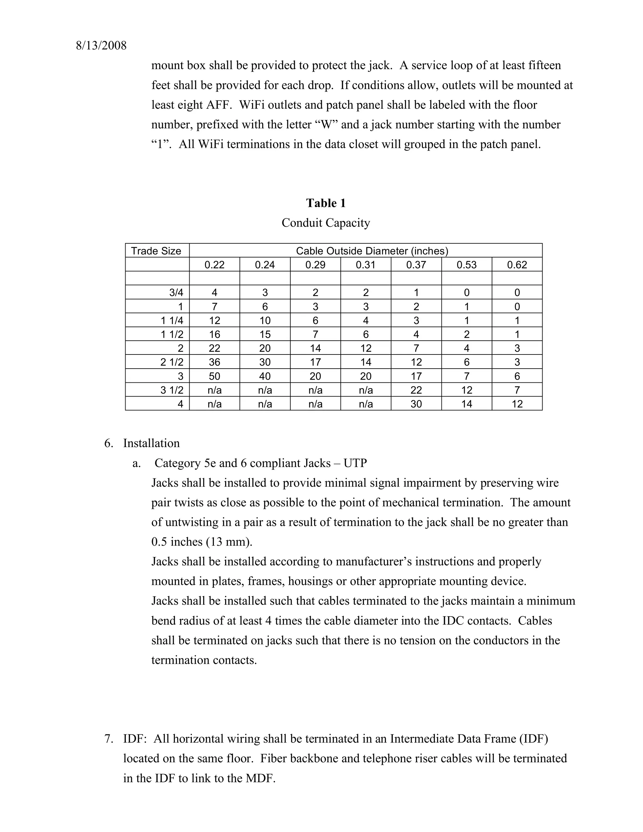
This document outlines standards and specifications for data and telephone cabling installation at The New School University. It details requirements for cable types, outlets, labeling, testing and contractor certification. All work must comply with ANSI/TIA/EIA standards and be performed by a Hubbell Mission Critical certified contractor to be eligible for warranty.
The expansion module MAC00-FP4 allows MAC motors to connect to a Profibus DP network. It acts as a Profibus DP slave and allows reading and writing of all motor registers through Profibus. The module has 6 isolated digital inputs and 2 isolated digital outputs. It connects to the motor with M12 connectors and to the Profibus network with M12 connectors for easy installation in harsh environments. Sample Profibus configuration files and PLC code are provided for quick setup.
This document provides descriptions of the connector and cable types used for different ports on a network switch. It describes the RJ-45 connectors and pinouts for 10/100 Mbps ports, the duplex SC connector for the 100Mbps fiber port, the 15-pin connector for the AUI port, and the 8-pin RJ-45 connector and cabling for the console port to connect to a PC, terminal, or modem. Rollover and straight-through cable schematics are shown.
EZtouch panels are color touchscreen panels that provide configurable alarm buttons and displays. They connect over Ethernet or RS485 to an EZcall TPH host, which can support up to 100,000 panels. The panels are available in 2 sizes, have an IP65 rating, and configurable buttons. They provide an affordable way to initiate or display alarms anywhere.
This document is a catalog for structured cabling products including:
1. Work area outlets such as connectors, faceplates, jacks, and boxes for copper and fiber optic cabling.
2. Rack and cable management products like racks, cable managers, shelves, and accessories.
3. Residential enclosures and patch panels for small work areas.
4. Premise cables, pre-terminated cables, patch cords, and fiber optic components.
5. Raceway, wiring ducts, and accessories for cable routing.
It provides product descriptions, part numbers, and packaging information for a wide range of structured cabling infrastructure components.
netSELECT is an innovative networking solution for homes and small offices that provides dependability, flexibility, and easy upgradability. It offers Category 6 and 5e solutions including jacks, faceplates, patch cords, cable, and panels that meet industry standards and support Gigabit Ethernet. The solutions prioritize quick and reliable installation while maintaining high performance and value.
The document summarizes a valve terminal from Festo called the Valve terminals type 10 CPV, Compact Performance. It has an innovative cubic design that provides exceptional performance while being lightweight. It also offers versatile, reliable, and easy to mount features. A online configurator is available to help select and order a suitable valve terminal according to the user's requirements.
The document describes a professional cable TV signal analyzer called the Rohde & Schwarz EFL210. Some key features include its specialized design for detecting leakage signals across a wide frequency spectrum, robust carrying case for field use, ergonomic shape for comfortable one-handed operation, and integrated high-resolution color screen. The analyzer performs a variety of cable TV measurements on analog and digital transmissions through an intuitive interface and menu structure.
The document provides installation and configuration instructions for the B420 Ethernet Communication Module. It describes how to physically install the module, set the module address using a rotary switch, and connect the module to an Ethernet network and compatible control panel. It also explains how to determine the module's IP address or hostname for accessing the module's web configuration pages. The web pages can then be used to configure advanced network and security settings.
This document provides specifications for the DigiFlex® PerformanceTM Servo Drive DPEANIU-C100A400. It is a fully digital servo drive designed to drive brushed and brushless servomotors in torque, velocity, or position mode. Key features include an EtherCAT interface, support for various feedback devices, programmable I/O, and compliance with RoHS and pending UL/cUL and CE approvals. It provides a peak current of 100A and continuous current of 50A from an AC supply voltage of 200-240VAC or DC supply voltage of 255-373VDC.
A mobile jammeris a device which is used to jam signals of cell phone from receiving signals from base stations. Mobile jammer is used majorly where the disturbances that are occurred with the cell phones. So, in this paper we are designing a new Mobile Jammer unit which is capable of blocking the cell phone working not the signal receiving from Base Station, which make effective use of the situation where jammers actually used. This was implemented using FPGA by interfacing Mobile Device, RF Transmitter and RF Receiver and LCD Unit. G. Sugumar | Mrs. T. Sathiyabama "FPGA Based Wireless Jamming Networks" Published in International Journal of Trend in Scientific Research and Development (ijtsrd), ISSN: 2456-6470, Volume-3 | Issue-6 , October 2019, URL: https://www.ijtsrd.com/papers/ijtsrd29343.pdf Paper URL: https://www.ijtsrd.com/engineering/computer-engineering/29343/fpga-based-wireless-jamming-networks/g-sugumar
Industrial Modbus TCP/IP Protocol to its easily-integrated industrial management level products that come with SCADA/HMI system and other data acquisition systems on factory floors. Moreover, the industrial IT SNMP network is upgraded to the Industrial automation Modbus TCP/IP network.
1-port RS232/422/485 Modbus Gateway, IMG-210xT Series, a bridge that converts between Modbus TCP/IP Protocol and Modbus RTU/ASCII Protocol. It features a wide operating temperature range from -40 to 75 degrees C and a compact but rugged IP30 metal housing.
Contact us
Tel: +91-7875432180 Email: sales@bbcpl.in
Website: https://www.bbcpl.in
The MC1XDZC02-QD mounting card is designed to host DZC or DZXC series digital servo drives. It provides a compact assembly with readily accessible connectors and switches. The mounting card utilizes quick-disconnect terminals and mounts the drive on its underside, providing easy access. It is ideal for prototyping and integrating the digital servo drives into machines.
The MC1XDZC02 mounting card is designed to host DZC or DZXC series digital servo drives. It provides connectors and interfaces to integrate the drive into a machine. The mounting card supports various drive models and feedback types and includes signal conditioning, configuration switches, and CANopen communication.
VIA EPIA-P910-A Front I/O extender cardVIA Embedded
Hardware manual the Front I/O extender card for our popular EPIA-P910 quad-core x86 Pico-ITX board.
Get them at
http://www.viaembeddedstore.com/boards/x86-boards/via-epia-p910-10q-pico-itx.html
This document provides information on the DigiFlex® PerformanceTM Servo Drive DPEANIU-C060A400. It is a digital servo drive designed to drive brushed and brushless servomotors in torque, velocity, or position mode. It features an EtherCAT interface and supports various motor feedback types. The drive provides programmable digital and analog inputs and outputs to interface with external devices. It has a peak current rating of 60A and is compliant with RoHS and pending UL/cUL and CE approvals.
The document provides an operation manual for the DV Promix 3 portable audio mixer. It includes 3 pages of contents and sections on the panel layout, inputs, outputs, meters, powering, construction, interfacing, warranty and specifications. The inputs section describes the balanced XLR inputs, input level settings for different signal types, microphone powering including 48V phantom power, and low cut filters. The outputs section covers balanced XLR and 3.5mm outputs and output limiters.
Expand audio system possibilities with REAC and MADI
S-MADI. The S-MADI REAC Bridge is a bi-directional signal converter between REAC and MADI. This bridge enables connectivity between MADI-equipped digital audio mixers/systems to any REAC-based devices such as the popular M-48 Personal Mixing System, Digital Snakes, V-Mixer Consoles, and Multi-channel Live Recording.
Enable new Digital Snake possibilities by merging up to four REAC devices. The S-4000M REAC Merge Unit allows up to four Digital Snake heads to be merged into a REAC stream where the master device recognizes it as single REAC slave unit. This important technology enables distribution of multiple input/output units around a location, venue or stage for flexible point-to-point digital snake or V-Mixing System configurations.
The BG-12LX is an addressable manual pull station that can be surface mounted or semi-flush mounted. It includes a dual-action handle that must be pushed in and pulled down to activate the alarm. When activated, the handle latches down and the word "ACTIVATED" is visible. It connects to the fire alarm control panel via two wires on the SLC loop. The station address is set using rotary decimal switches.
This document provides information about sample projects related to campus/corporate planning, workplace change management, and alternative workplace strategies. It discusses a 30 acre owned/leased campus with 1,006,200 square feet of occupied space and a population of 2,400. It also outlines a 5 year campus site planning projection with a 3% annual growth rate. Finally, it describes new workplace initiatives focused on enabling innovation, strengthening community, and inspiring talent through open plan workspaces, collaborative rooms, and telework suites.
Featured Houston Office Space: Level-5 Design Boxer Property
As an architectural design and construction management company, Level-5 Design stood out to us in one of our favorite pieces of architecture, Arena Place. We stopped for an expert's opinion on office space.
The document provides cost estimates for different levels of office build outs. A basic office is estimated between $32-$42 per square foot and involves painted drywall, doors and frames, lighting and power outlets. An upgraded office is $43-$55 per square foot and includes upgrades like sound baffles and vinyl wall coverings. A premium office is $56 per square foot or more and features high quality finishes, custom millwork and premium flooring. The costs provided are estimates only and do not include items like furniture or additional fees that could increase the overall costs.
Judged by an international panel of judges, the Singapore Design Awards (SDA) honours outstanding product, graphic, new media, interior, packaging and multi-disciplinary design projects. This year, DAS awarded 63 outstanding entries.
The Awards began in 1998 and was unveiled by the then Prime Minister of Singapore Mr Lee Kuan Yew at the first Singapore International Design Forum. The initial inspiration for the awards which is to raise awareness for the region and the strategic role of design remains essentially the same.
The document provides an overview of different interior space programs including interior space programs, site selection programs, furniture programs, and budget programs. It describes the purpose and process for each type of program. An interior space program determines space, furniture, and equipment needs. It includes collecting organization and operations information, quantitative space calculations, and planning recommendations. A site selection program assists in finding an appropriate site through comparative site analyses. A furniture program analyzes existing inventories and identifies new furniture needs. A budget program establishes construction and furniture/fixture/equipment budgets.
ATD's Design Services Group compliments your company's strategy for business expansion or change by supporting a clear and concise process for design services, with performance, quality and professional execution. As a customer, you can be assured you are getting the most appropriate and advanced products for your project from a company that will be there for you time and time again.
The document provides background information on the Department of Neighborhood Development (DND) in Boston and a mid-rise building located in Cambridge that is being considered as a potential housing site. The DND is responsible for developing affordable housing and has received $35.4 million in federal funds since 2008 to support housing and economic development programs. The building under consideration is located near Kendall Square and MIT and has ground floor space available. It is in a diverse area near public transportation.
This document contains architectural standards and dimensions for interior spaces, furniture, and fixtures. It includes human scale drawings, different ways to draw doors, and how to measure objects with hands. Specific interior standards are provided for elements like stairs, kitchens, living rooms, bathrooms, sinks, showers, and more. Furniture dimensions are listed for areas like living rooms, bedrooms, dining rooms, and bathrooms. The document also outlines right and wrong ways of placing furniture, painting, using spaces, and dimensions for items like billiard tables, ping pong tables, and televisions.
This document outlines architectural standards for a senior secondary school. It provides requirements for various teaching spaces including standard classrooms, science labs, a library, auditorium, play areas, and gymnasium. It also includes standards for administrative spaces, sanitation facilities, and other support spaces. Requirements include the size, shape, floor area, and special provisions for different types of rooms. Ventilation, electrical services, and accessibility are also addressed according to their functions.
This document provides information on ATEX/IECEx certified PowerPlex panelboards for use in hazardous locations. Key details include:
- The panelboards are rated for Zone 1 and 2 hazardous areas and certified to ATEX and IECEx standards.
- They feature individual breaker housings to allow for easy servicing without downtime, and fiberglass reinforced polyester enclosures.
- The catalog number guide provides steps for selecting panel configuration including main breaker size, number of branch circuits, breaker ratings and options.
- Standard panel arrangements accommodate 1 to 72 branch circuits in various configurations depending on breaker pole size.
EtisalatTelecom Model 2016 modified.pptxssuser8298f2
This document provides installation guidelines and requirements for various telecommunications site equipment. Some key points include:
- Antennas, cables, and other equipment should be installed according to approved design specifications and arrangements. Proper sealing, labeling, and fastening is required.
- Site layouts and wiring diagrams are provided as examples for indoor and outdoor installation of cabinets, racks, cables, and other gear.
- Specific installation, configuration, and testing instructions are given for items like antennas, radios, fiber cables, power equipment, batteries, and alarms. Proper grounding, arrangement, and labeling is emphasized.
- Photographs show examples of proper installation of equipment like cabinets, cable management, labeling,
This document provides guidelines for internal cabling within various types of buildings. It outlines standards for residential premises, multi-storied buildings, business premises, and compounds. For each type of building, it specifies the necessary telecommunications infrastructure components like main distribution boxes, telecom rooms, optical distribution frames, and specifies cable types and placement of telecom outlets. It also provides general cabling standards regarding separation of telecom cables from power cables, labeling of infrastructure, maximum cable spans, and avoidance of aerial cabling.
This document discusses cabling for networking devices. It identifies the components needed to connect routers and switches for LAN and WAN connectivity. It explains Ethernet and WAN cabling standards as well as how to set up console connections. Cable types, connectors, and configurations for straight-through, crossover, and rollover are defined for Ethernet and serial WAN implementations. Visual diagrams are also provided to illustrate physical network topologies and device interfaces.
This document provides instructions for assembling a cable gland. It includes:
1) An overview of the cable gland components and their assembly order.
2) Detailed steps for preparing the cable and gland, including stripping lengths, spreading the armour, and tightening nuts.
3) Notes on accessories that may be required like shrouds or locknuts.
4) Specifications for the cable gland such as temperature range, certification standards, and cable acceptance sizes.
The document provides information on Profibus fieldbus connectors:
- The connectors are available in aluminum and stainless steel housings for connecting 1-8 measuring devices to a Profibus trunk line via spur lines.
- They feature tension clamp connection technology, overvoltage protection, fusing for individual spur lines, EMC cable glands, and M12 connectors.
- Variants are available for Profibus-DP and Profibus-PA networks with different technical specifications and connection options.
- Accessories and ordering information is provided for the Profibus connectors.
This document provides specifications for applying Category 6 modular plug connectors, including:
- Requirements for cable type, dimensions, and pair arrangement
- Steps for cable preparation including stripping, shield folding, and positioning pairs
- Instructions for inserting the cable into the wire holder and plug housing while maintaining pair twists
- References for related materials like product specifications, instruction sheets, and manuals
Structured Cabling Solution - White PaperSyed Firas
The document discusses structured cabling systems, which provide the foundation for modern communication networks. A structured cabling system includes all cabling, hardware, and pathways that connect devices from the data center to individual work areas. It is governed by standards to ensure flexibility and compatibility. The key components of a structured cabling system are the entrance facility, equipment room, backbone cabling, horizontal cabling, telecommunications closets, and work areas. Implementing a standardized structured cabling system allows networks to adapt over 15-20 years without disruption.
The document provides specifications for the electrical systems in a radiology room, including:
1) Raceway systems will be installed to route wiring for radiology equipment, with floor, wall, and ceiling troughs.
2) Wiring will include high voltage cables for equipment, and grounding conductors.
3) Installation will require coordinating with equipment layout and shielding, and certifications will be provided upon completion.
This document provides information on various types of outdoor fiber optic waterproof connectors. It describes 6 series of connectors: ODVA, Fullaxs, Mini-SC, ODC, field tactical, and aviation connectors. For each series, it provides details on features, specifications, compatible accessories, and example products. The document serves as a product manual for outdoor fiber optic waterproof connectors.
An optical network unit (ONU) is a device that transforms incoming optical signals into electronics at a customer's premises in order to provide telecommunications services over an optical fibre network.
A structured cabling system allows for constant moves and changes to be performed by on-site personnel with growth and flexibility built into the cabling scheme. It supports and outlives most network components while only representing 5% of the total network investment. A structured cabling system allows moves, adds, and changes to occur quickly and cost-effectively, preventing downtime that can cost between $1,000 and $50,000 per hour.
The Nexans Euromold compact version screened separable connector is suitable for high voltage HV cable termination up to 33kV. Interface Type C Euromold M16 bolted tee connectors up to 33kV are designed to connect and terminate polymeric (XLPE EPR) cables to M16 bolted 400 series equipment bushings. Nexans Euromold connectors are supplied in sets of three phases.
Nexans Euromold Kit Contents: 3 x connector housings, 3 x size sensitive cable reducers, 3 x conductor contact lug, 3 x clamping screws and 3 x insulating plugs & caps.
Euromold Connectors 400 Series Interface Type C Bushing - 630Amp
* Connector Type : M16 Bolted Copper Insert
* Voltage Range : 11/12kV-33/36kV
* Current Rating : 630amps
* Specification : CENELEC EN50180 & EN50181
Euromold 430TB Elbow Connectors are used with 400 Series Interface C Bushing.
Nexans Euromold tee connectors are designed for terminating high voltage XLPE power cables into compact switchgear to make optimum use of limited installation space.
Nexans, the worldwide leader in the cable industry, has extended its well-proven range of compact high voltage (HV) connectors with two new tee-shaped connectors designed specifically for use with compact switchgear and transformers now being specified for wind turbine applications. The Nexans Euromold M430TB connector is for use with higher voltages (up to 33-36kV) and the M434TB connector is for higher currents (up to 1,250 A).
Trend Towards Compact Switchgear for Wind Turbines
The growing trend towards using ever more compact high voltage switchgear in wind turbines has resulted in smaller cable boxes, limiting the space available for connectors. Nexans has responded to this challenge by developing its new asymmetric tee-shape connectors to create a compact connection solution. This now enables two cables to be connected in the same space required for one cable using a traditional non-compact connector. As well as being ideal for all applications where space is a limiting factor, the Nexans compact connectors also enable users to increase the capacity of an existing installation.
EPDM Jacket: A Key Design Feature for Safety and Reliability
The Nexans Euromold M430TB and the M434TB are separable tee-shape bolted connectors designed to connect high voltage polymer-insulated cable to wind turbine equipment such as switchgear and transformers- they can also be used for cable to cable connections with the appropriate mating parts. A key design feature is the thick (3 mm) EPDM (Ethylene Propylene Diene Monomer) rubber conductive insulation jacket that provides a total safe to touch screen for personnel safety, this is both more reliable and longer lasting than the painted silicone rubber insulation used in many connectors.
400 Series Interface C Compact Nexans Euromold Cable Connectors and Bushings connect and terminate HV cables to Interface C bushings on switchgear and transformers.
Nexans Euromold provide high voltage cable accessories to suit the 7 main bushing interfaces : A, B, C (Compact), C (Symmetrical), D, E and F.
Nexans Euromold cable joints, cable terminations, epoxy bushings, angled (elbow) and straight plug-in or bolted separable connectors for connecting, jointing and terminating high voltage cables.
This document is a catalogue from Nexans Network Solutions Division Euromold that describes their medium voltage separable connectors and bushings. It provides information on Euromold's product range including tee connectors, equipment bushings, and accessories. It also provides ordering instructions, technical specifications, standards compliance, and diagrams for the different products.
Nexans Euromold Interface E 5/8" 700 Series Cable Connectors
Wiring standards
1. 8/13/2008
Office of Information Technology
7/10/2008
Standards
for
Data and Telephone Cabling
1. This standard details the contractor responsibilities for installation of the data and
telecom wiring at The New School University (TNS). Data wiring plans will be released
as available.
2. Unless otherwise specified, all material is to be supplied by the wiring contractor.
3. All work on any project shall be in accordance with the procedures and practices of
ANSI/TIA/EIA 568-B-1, ANSI/TIA/EIA 568-B-2 plus addendums, ANSI/TIA/EIA 568-
B-3, TIA/EIA 569-A-3, TIA/EIA 606-A, TIA/EIA 607 and TIA/EIA-604-14A.
4. Cable Specifications:
a. Horizontal cable cables from the IDF to each work area outlet (WAO) shall be
General Cable blue, 4 pair, plenum rated 100Ω Category 6, P/N 7131688 or
equivalent.
b. Horizontal telephone cables from the IDF to each work area outlet (WAO) shall be
General Cable white, 4 pair, plenum rated 100Ω Category 5e, P/N 5131450E. or
equivalent
c. Unless otherwise specified, the data backbone between each IDF and the MDF shall
either be 24 strand 50/125µm multimode interlocking armored cable and/or, a
minimum of six (6) enhanced Cat 6 cables, as specified by The New School.
d. The telephone backbone between the IDFs and the MDF shall be multiple 25 or 50
pair plenum rated Cat 5e cables, General Cable P/N 39419-50WH or P/N 30171-
100WH or equivalent. The number and mix of cables is to be determined by the
wiring contractor. At least 10% of the pairs shall remain as spares for future
growth.
e. Cable TV shall be quad shielded plenum rated RG6 coax with F-Type connectors.
TV terminations shall be to a dedicated wall plate in the work area and to the cable
company point-of-presence on the transmission end.
f. All backbone cables shall be supported in the vertical cable duct per TIA/EIA-568-
B.
g. Horizontal support for both backbone and horizontal work station cables to the IDF
will be in The New School supplied ladder racks, trays or conduit for open ceilings.
2. 8/13/2008
In closed ceilings, cabling may be supported from installed “black iron”, wiring
contractor supplied “J” rings or in The New School supplied conduit. Where
conduit is required, a pull box will be installed at every second ninety degree bend.
Pull boxes will be large enough to accommodate a bend radius of at least eight (8)
inches.
5. Work Area Outlets:
a. Horizontal cable distribution from the IDF to the work areas will be via TSU
provided overhead ladder racks or raceway unless otherwise specified. Both data
and telephone cables shall be installed in these racks or raceway. Where the WAO
is in an enclosed office, cables will pass through a drop ceiling and cables shall be
ceiling mounting in accordance with current EIA/TIA standards.
b. TSU electrical contractor will provide single gang wall boxes with ¾“stubups for
the WAO in all enclosed offices. Where more than three cables are to be installed
in the WAO, the stubup will be sized in accordance with Table 1.
c. Where there are open office area spaces with office partitions. Cables to these open
offices shall run from the ladder rack through NSU installed vertical conduits and
through the partition cableway in the partitions to the work area.
d. Unless otherwise specified, two data outlets shall be provided for each user. The
data jacks shall be Hubbell Xcelerator, blue, Category 6: Hubbell P/N HXJ6B.
Each data jack shall have one data cable wired in the TIA/EIA 568B configuration.
e. Unless otherwise specified, two telephone outlets shall be provided for each user.
The telephone jacks shall be Hubbell Xcelerator, office white, USOC 6 position:
Hubbell P/N HXJUOW. Each telephone jack shall have one data cable with two
pairs from the Cat5e cable terminated in a USOC RJ14 configuration.
f. Unless otherwise specified, the closed office jacks will be mounted in a Hubbell 4
Port office white faceplate P/N IFP14OW. The two data jacks shall be mounted in
the lower two positions and the two telephone jacks in the upper two locations.
g. Unless otherwise specified, the open office jacks will be mounted in a in a Hubbell
furniture plate, P/N FP4BBK, which fits the standard ANSI/TIA/EIA furniture
opening. The two data jacks shall be mounted on the right side of the furniture
plate and the two telephone jacks on the left.
h. When audio/visual A/V cabinets are to be installed, the contractor will provide a
Hubble four (4) port faceplate with four (4) data outlets as noted above.
i. Outlets noted as WiFi shall be terminated in a single port outlet. The data jack shall
be a Hubbell Xcelerator, yellow, Category 6: Hubbell P/N HXJ6Y or equivalent.
Where the termination is to be in the ceiling or ladder rack, a single jack surface
3. 8/13/2008
mount box shall be provided to protect the jack. A service loop of at least fifteen
feet shall be provided for each drop. If conditions allow, outlets will be mounted at
least eight AFF. WiFi outlets and patch panel shall be labeled with the floor
number, prefixed with the letter “W” and a jack number starting with the number
“1”. All WiFi terminations in the data closet will grouped in the patch panel.
Table 1
Conduit Capacity
Trade Size Cable Outside Diameter (inches)
0.22 0.24 0.29 0.31 0.37 0.53 0.62
3/4 4 3 2 2 1 0 0
1 7 6 3 3 2 1 0
1 1/4 12 10 6 4 3 1 1
1 1/2 16 15 7 6 4 2 1
2 22 20 14 12 7 4 3
2 1/2 36 30 17 14 12 6 3
3 50 40 20 20 17 7 6
3 1/2 n/a n/a n/a n/a 22 12 7
4 n/a n/a n/a n/a 30 14 12
6. Installation
a. Category 5e and 6 compliant Jacks – UTP
Jacks shall be installed to provide minimal signal impairment by preserving wire
pair twists as close as possible to the point of mechanical termination. The amount
of untwisting in a pair as a result of termination to the jack shall be no greater than
0.5 inches (13 mm).
Jacks shall be installed according to manufacturer’s instructions and properly
mounted in plates, frames, housings or other appropriate mounting device.
Jacks shall be installed such that cables terminated to the jacks maintain a minimum
bend radius of at least 4 times the cable diameter into the IDC contacts. Cables
shall be terminated on jacks such that there is no tension on the conductors in the
termination contacts.
7. IDF: All horizontal wiring shall be terminated in an Intermediate Data Frame (IDF)
located on the same floor. Fiber backbone and telephone riser cables will be terminated
in the IDF to link to the MDF.
4. 8/13/2008
a. Data cables shall be terminated on one or more Hubbell Category 6e 48 Port Patch
Panels P/N P648U. All terminations shall be T568B.
b. The contractor shall install a fire retardant plywood sheet on the IDF wall for
mounting 110 type terminal blocks. All telephone cables shall be terminated on one
or more Hubbell 100 or 300 pair 110 blocks, P/N 110BLK100BWL or
110BLK300BWL, as required. All 4 pairs will be terminated on the 110 block.
c. The telephone riser cables will terminate on a Hubbell 300 pair 110 block. Multiple
50 or 100 pair cables, as required to support the number of users on a floor, shall be
provided by the contractor. The wiring contractor shall cross connect the horizontal
and riser cables with one cross connect for each active phone pair.
d. One 24 strand, inter-locking, armored, 50/125µm, multimode fiber cable will be
used to connect each IDF to the MDF. The strands shall be terminated with SC
fiber connectors in a 24 port rack mount panel, Hubbell P/N FPR024SCM.
e. A standard 84 inch high EIA19 inch rack will be installed by the contractor in each
IDF. The rack will aluminum and be drilled for #12-24 machine mounting screws.
The rack will be solidly affixed to the floor and be bonded to the building ground
with a minimum #6 AWG wire in accordance with TIA/EIA-607.
f. Data racks shall have contractor supplied horizontal and vertical wire managers.
The vertical managers, matching the rack, may be specified by the contractor and
the horizontal wire manager shall be Hubbell four ring panel P/N HC119MS3N.
8. MDF: The MDF for any building will be specified by The New School. Dependant on
the number of terminations, one or more standard 84 inch high EIA19 inch racks are to
be provided, to be specified by The New School. The racks shall be bonded as noted in
Para. 7e. A fire retardant plywood sheet shall also be installed for termination of the
telephone backbone and horizontal telephone connections for the floor on which the
MDF is located.
a. All the fiber backbone cables will be terminated with SC fiber connectors in a 24
port rack mount panel, Hubbell P/N PR024SCM. The panels are to be installed at
the top of the rack.
b. The horizontal data cables shall be installed as noted in Para. 6a.
c. The telephone riser cables from each IDF shall be terminated on 110 blocks on the
plywood backboard. A set of 110 blocks shall be dedicated to each floor. NSU will
be responsible for cross connecting all active pairs to the telephone switch.
9. Roof Riser
5. 8/13/2008
a. If required in the building, one 24strand, inter-locking, armored, 50/125µm,
multimode fiber cable will be used to connect the MDF to the roof. The one side
shall be terminated in the MDF with SC fiber connectors in a 24 port rack mount
panel, Hubbell P/N FPR024SCM.
b. The roof side shall be terminated in a location specified by the NSU. The
terminations shall be SC and housed in a 24 port Hubbell locking FTU wall mount
cabinet.
10. Labeling: All cables shall be labeled in accordance with standard TIA/EIA606-A, except
as noted herein.
a. Work Area Outlets shall have a machine printed label permanently attached
showing the building letter (D), room number and outlet letter, i.e. D-510A. Data
jack numbers shall be separately affixed and noted as D1, D2. The outlets will be
lettered sequentially going clockwise around the room (cubical) starting with the
first outlet next to the door or cubical entrance.
b. The patch panels in each IDF shall have machine printed labels permanently
attached showing the room number, outlet number and jack number. If there are
space restrictions, labels can be printed as D1, Room #, D2.
c. Horizontal telephone blocks will have a machine printed label for each four pair
cable noting the room number and outlet letter. The backbone telephone block shall
be labeled with room number, outlet number and pair number.
d. The backbone telephone blocks in the MDF. Each pair on the block shall be
labeled with the room number, outlet number and pair number.
e. As built drawings shall be supplied by the contractor showing the location and
labeling of the telecommunication outlets (see Attachment A).
f. All cross connect information, including WAO location, horizontal termination
positions at both ends and backbone/feeder terminations shall be supplied by the
contractor and included with the As Built Drawings (See Attachment B and C).
11. Testing
a. Category 5e and 6 compliant Jacks - UTP
Jacks shall be tested as part of the channel for Length, DC continuity, NEXT,
PSNEXT, Attenuation, Return Loss, ELFEXT, and PSELFEXT using the specified
hardware manufacturer's test heads and an industry standard level III tester per
ANSI/TIA/EIA-568-B.2 and B2.1 and ISO/IEC 11801, Class E compliance.
6. 8/13/2008
Testers shall be correctly set to test the type and manufacturer of the horizontal
cable used in the channel being tested, including the correct NVP.
A “PASS” indication shall be obtained for all channel tests when tested using the
appropriate level tester for the appropriate category.
All test data shall be recorded and submitted to TNS before the cabling plant will be
accepted.
b. Fiber Backbone
All backbone and horizontal fiber shall be tested as part of the channel in
accordance with TIA/EIA-568-B.3 and TIA/EIA-604-14A, Optical Loss
Measurements of Installed Multimode Fiber Cable Plant. The data will include the
end-to-end attenuation testing (one direction only) at 850nm and 1300nm and
connector loss testing at 850nm.
All test data shall be recorded and submitted to NSU before the cabling plant will
be accepted.
12. Contractor Certification
a. The cabling installation is to be preformed by a contractor who is certified by the
HUBBELL MISSION CRITICAL ® TRAINING PROGRAM.
b. Contractors performing the certified installation are to be properly registered in the
Hubbell Mission Critical ® warranty program.
For further information or comments, please contact®:
Richard Burger
55 West 13th Street
New York, NY 10011
e-mail: www.burger@newschool.edu
Tele: 212 229-5300 x4233