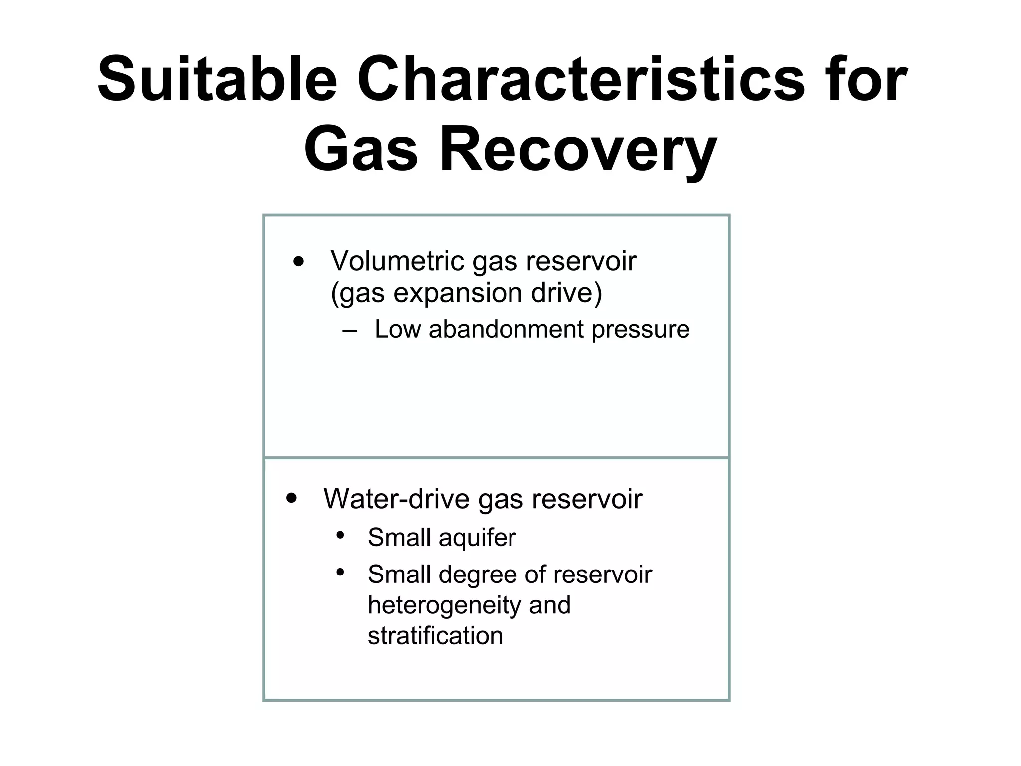
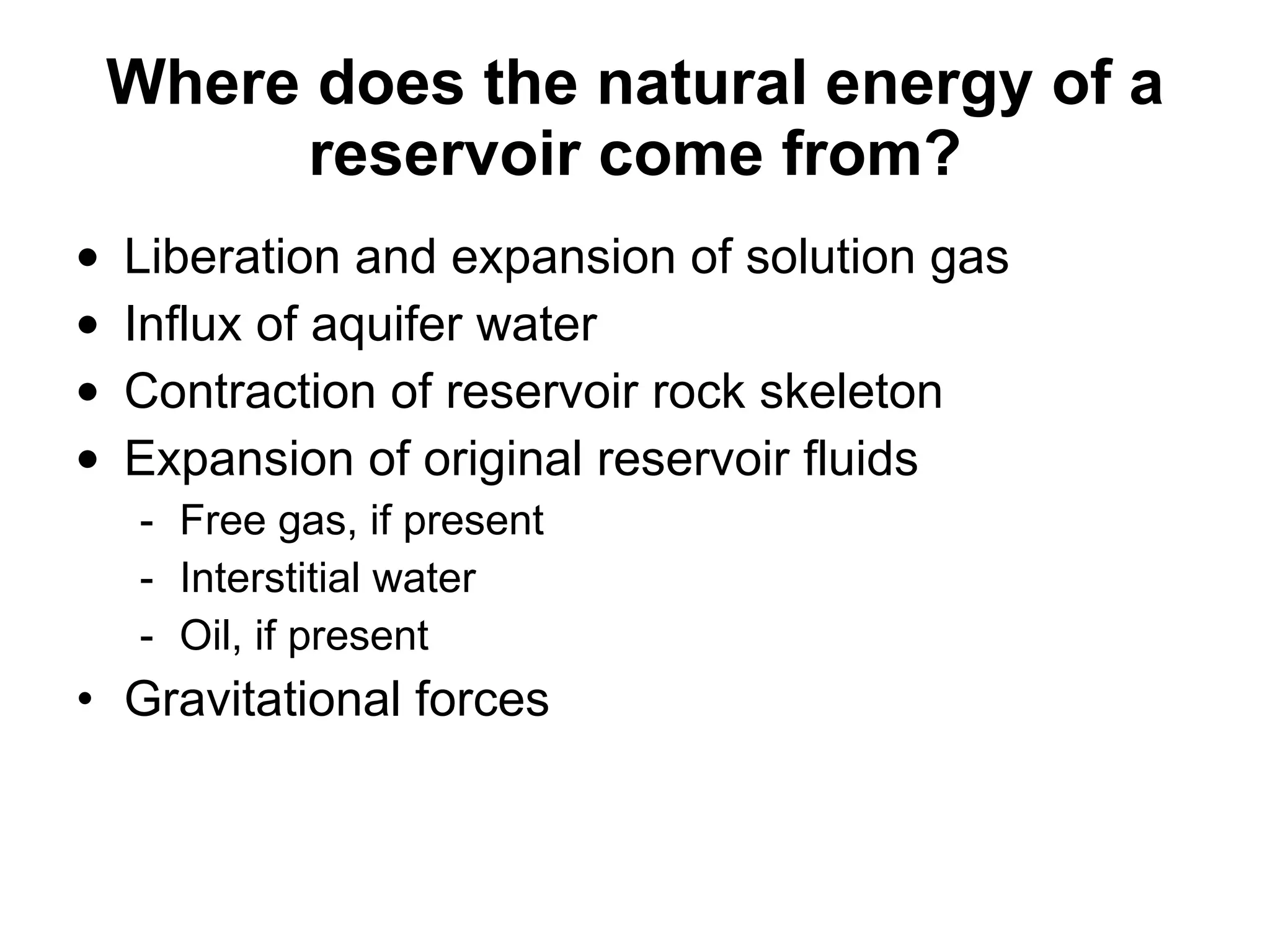
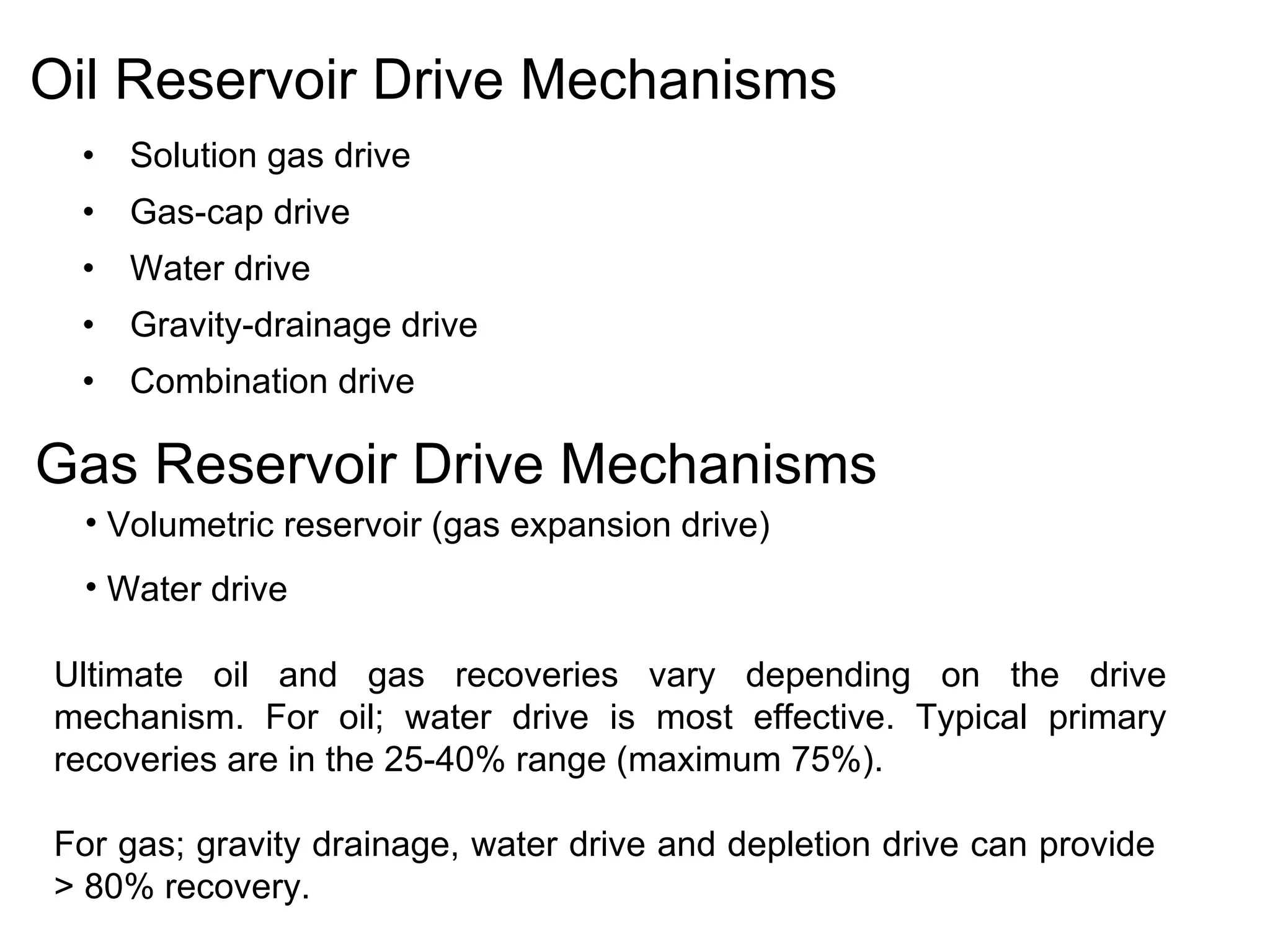
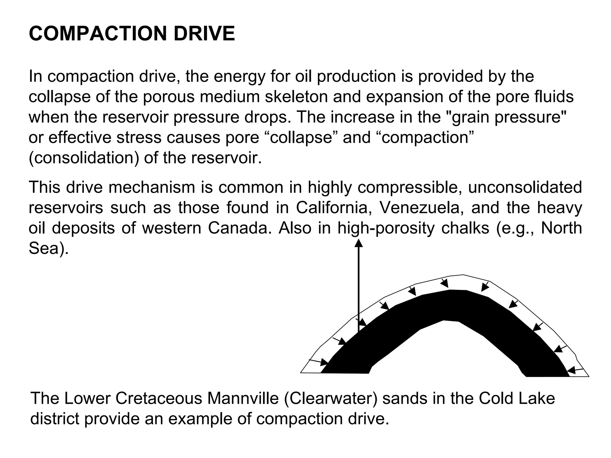
The document discusses various natural reservoir drive mechanisms that provide energy for hydrocarbon production including:
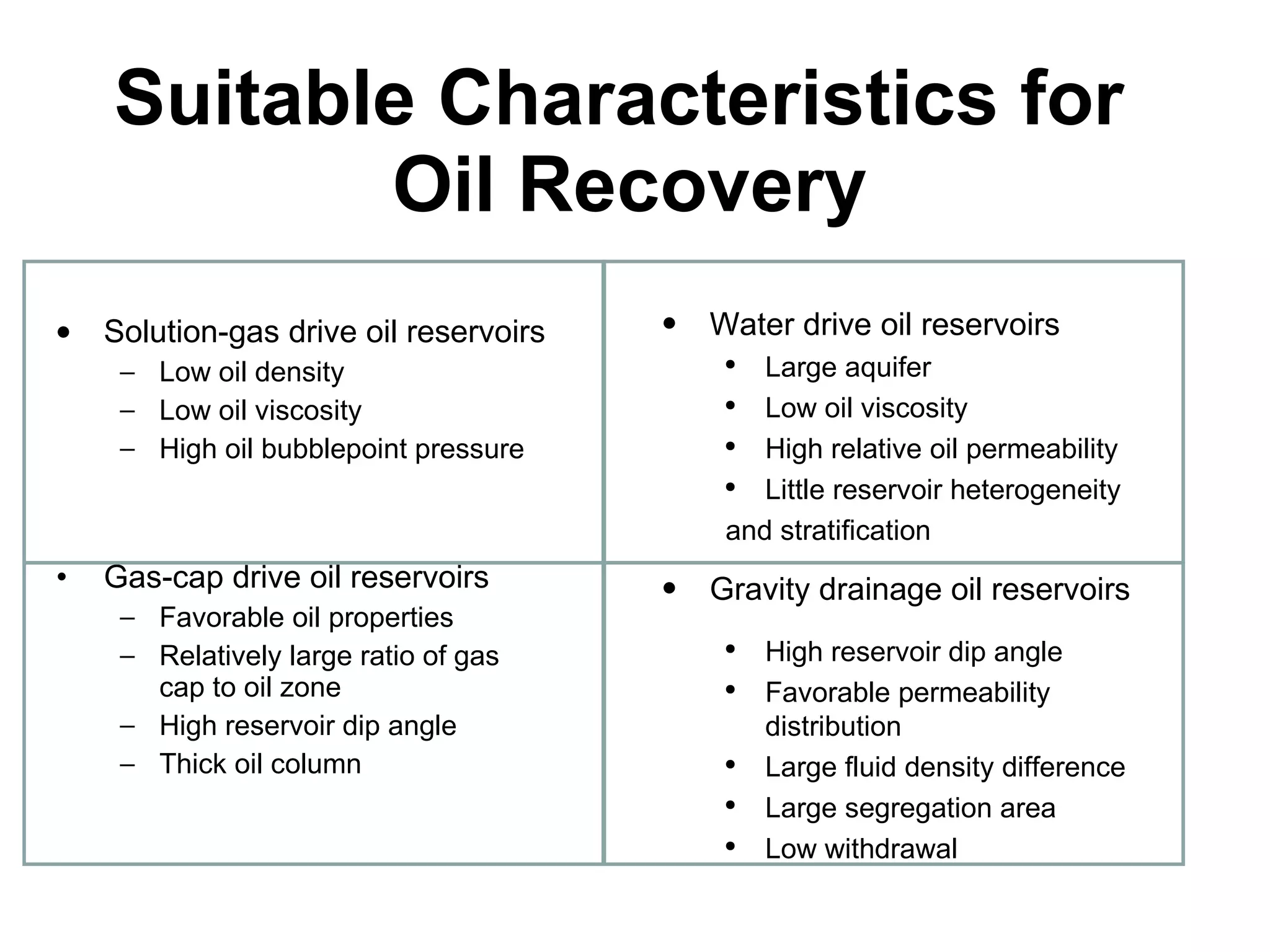
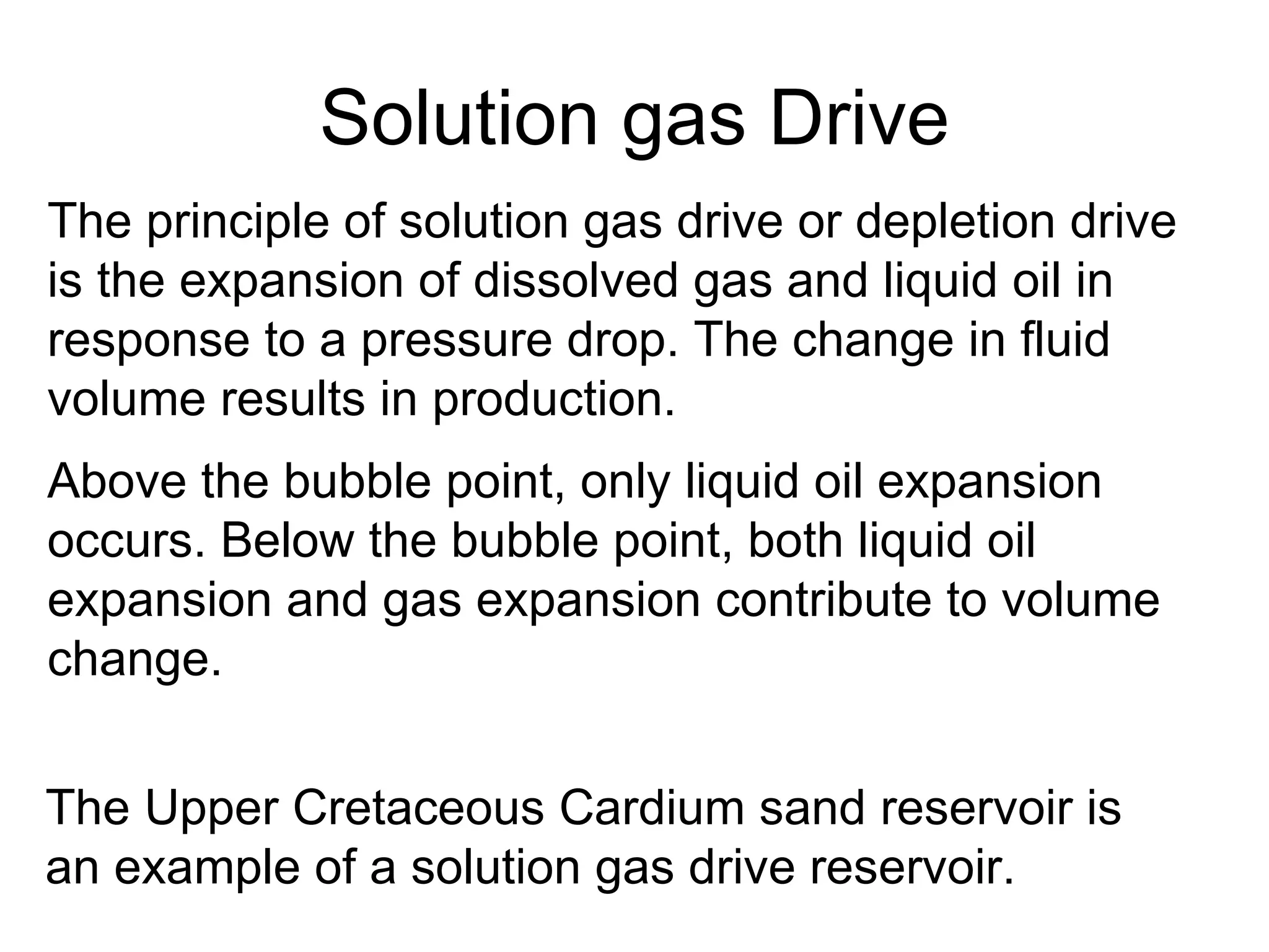
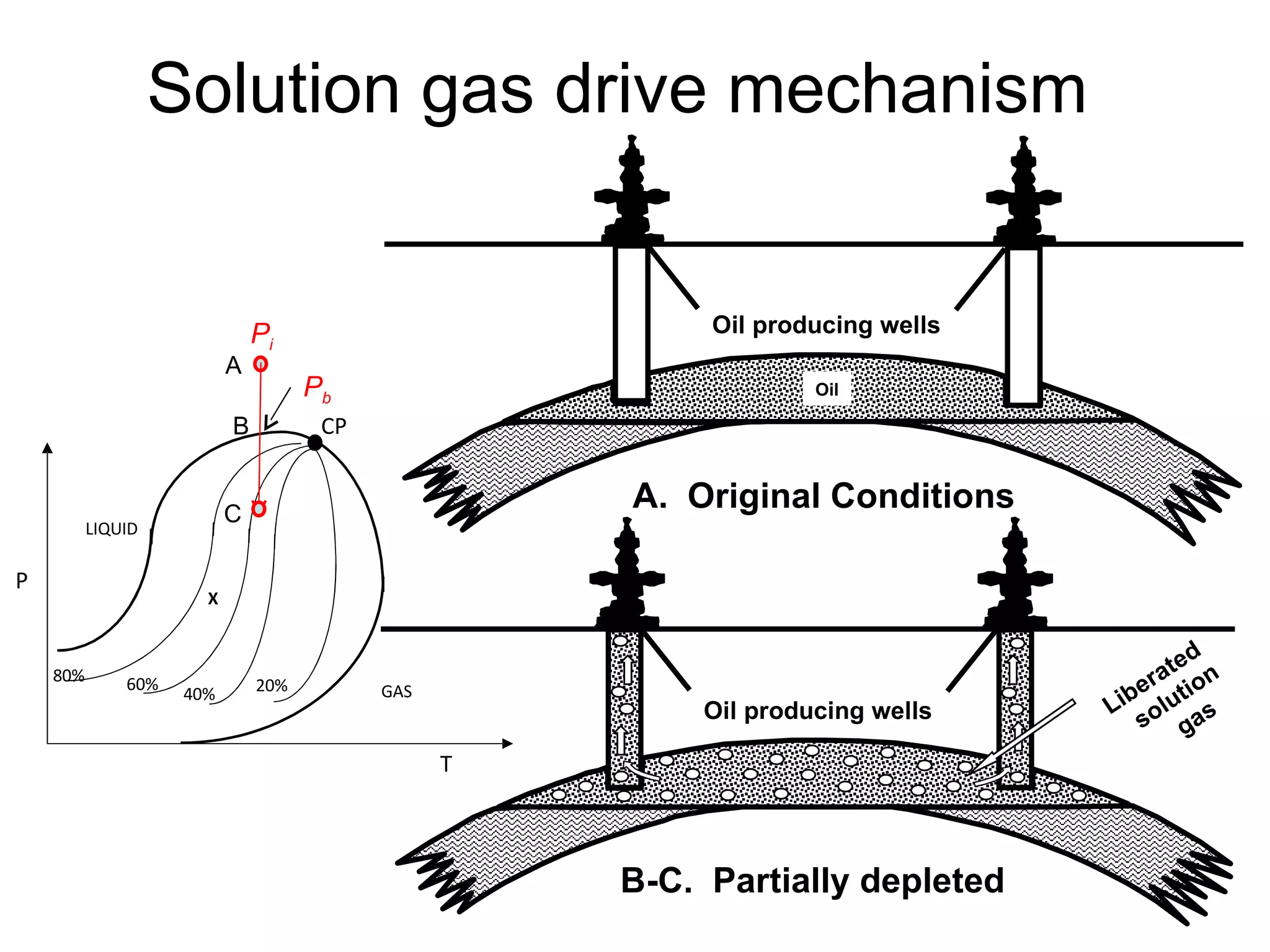
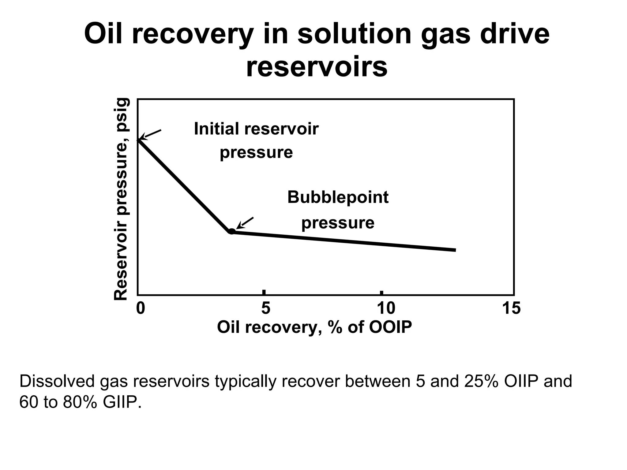
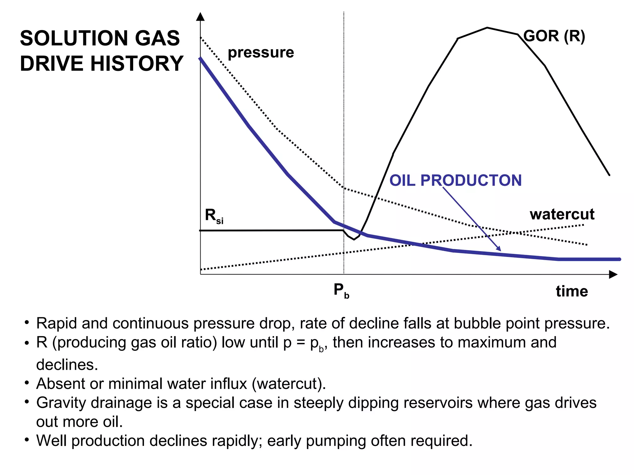
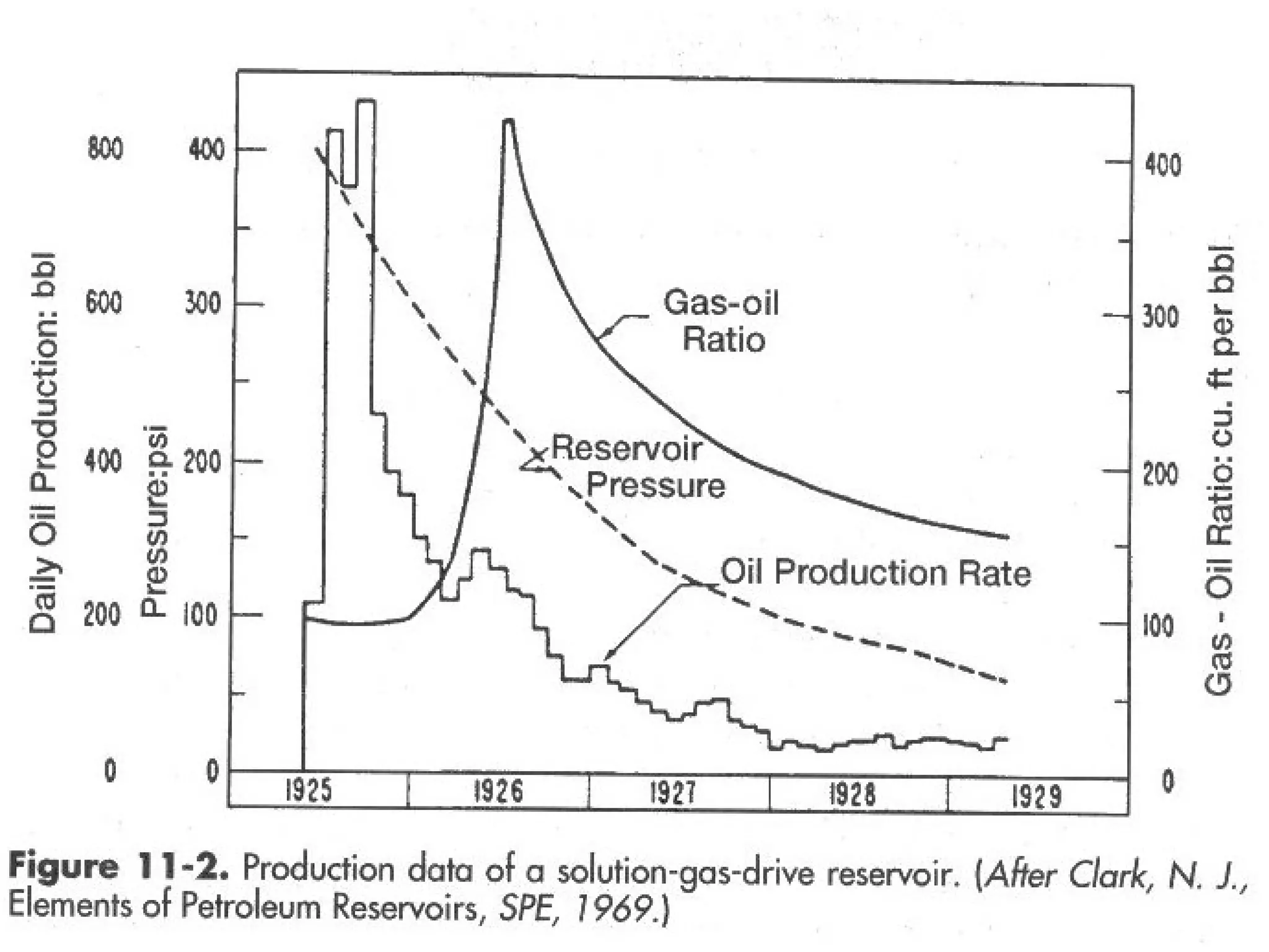
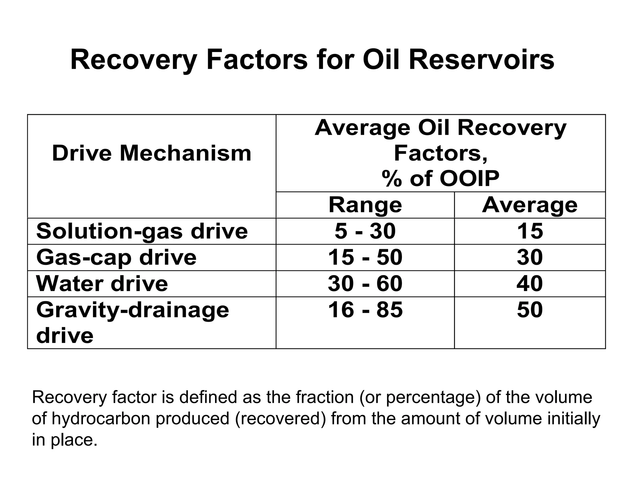
1) Solution gas drive where dissolved gas expands due to pressure drop, providing 5-25% oil recovery.
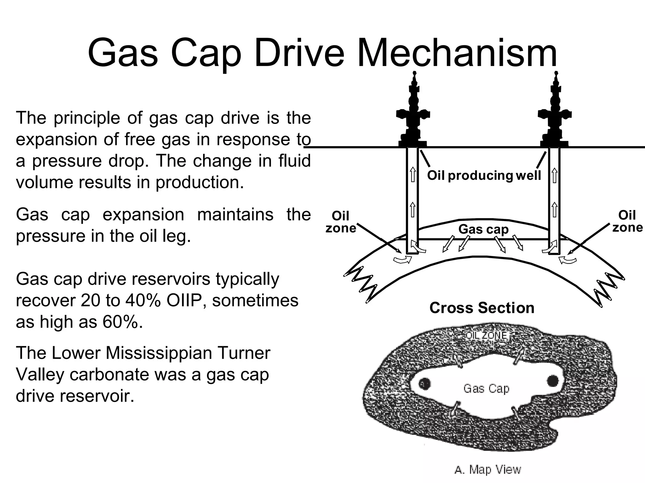
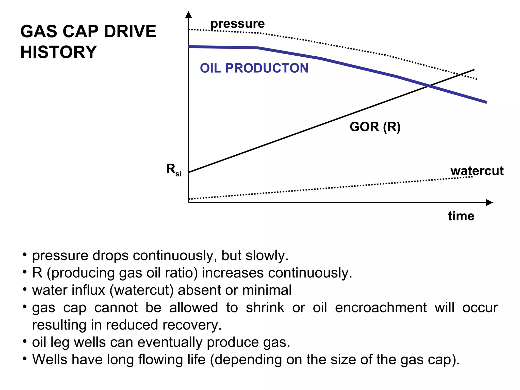
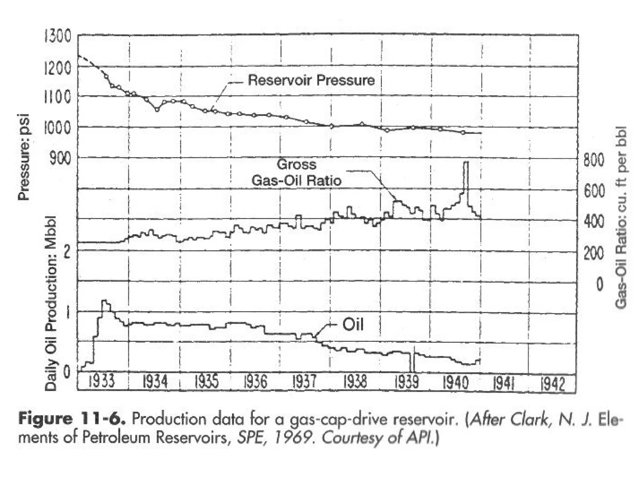
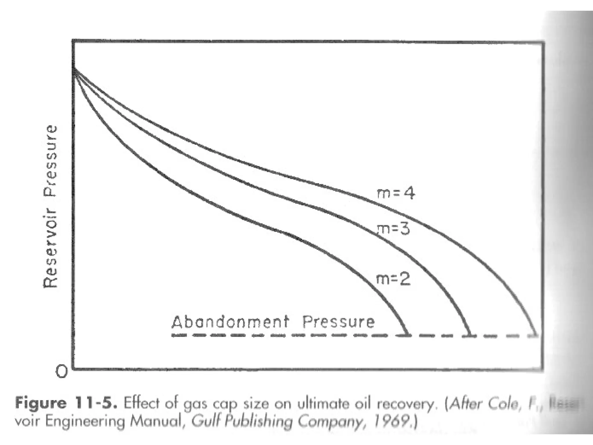
2) Gas cap drive where free gas expansion drives production, providing 20-40% oil recovery.
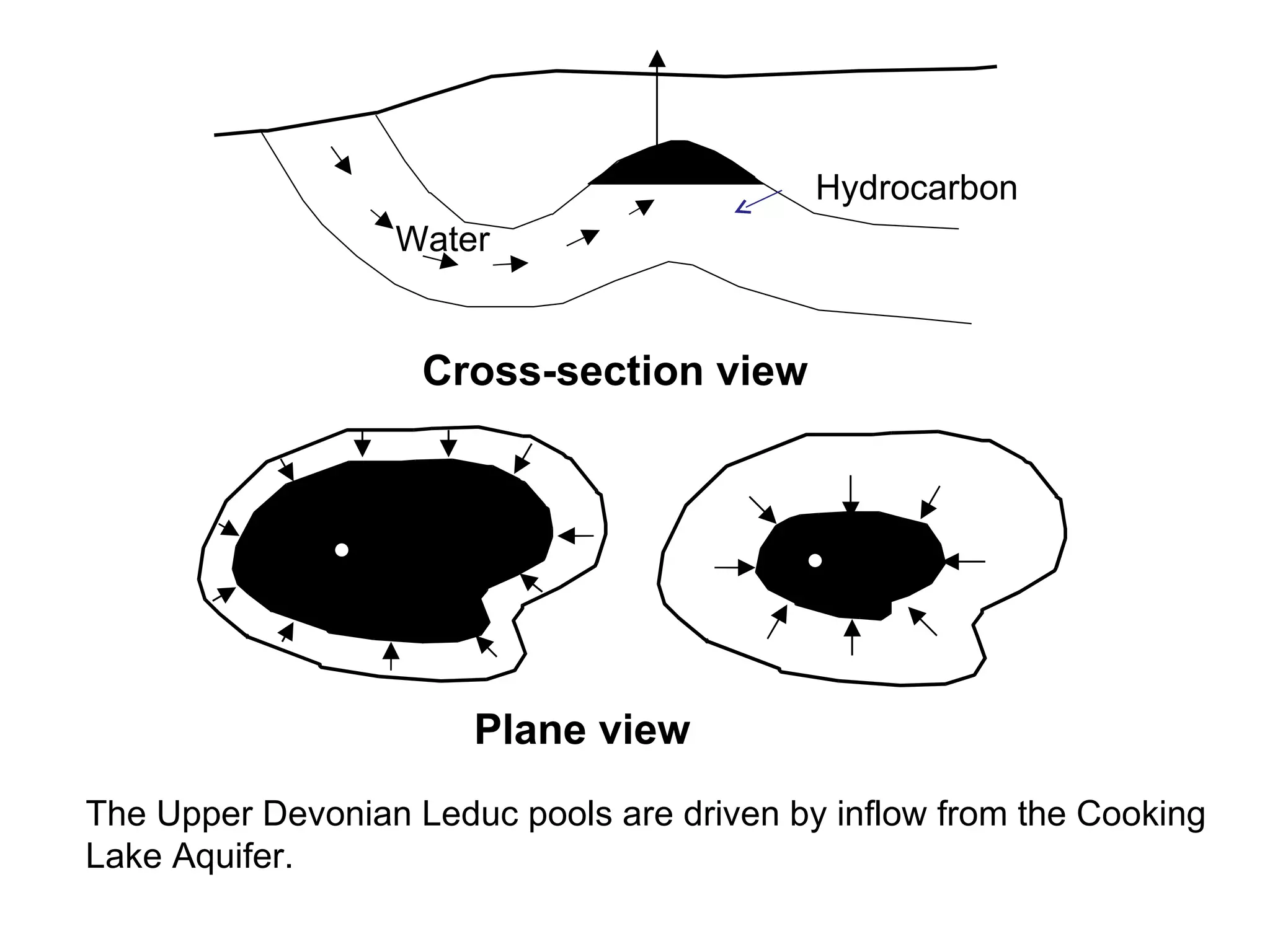
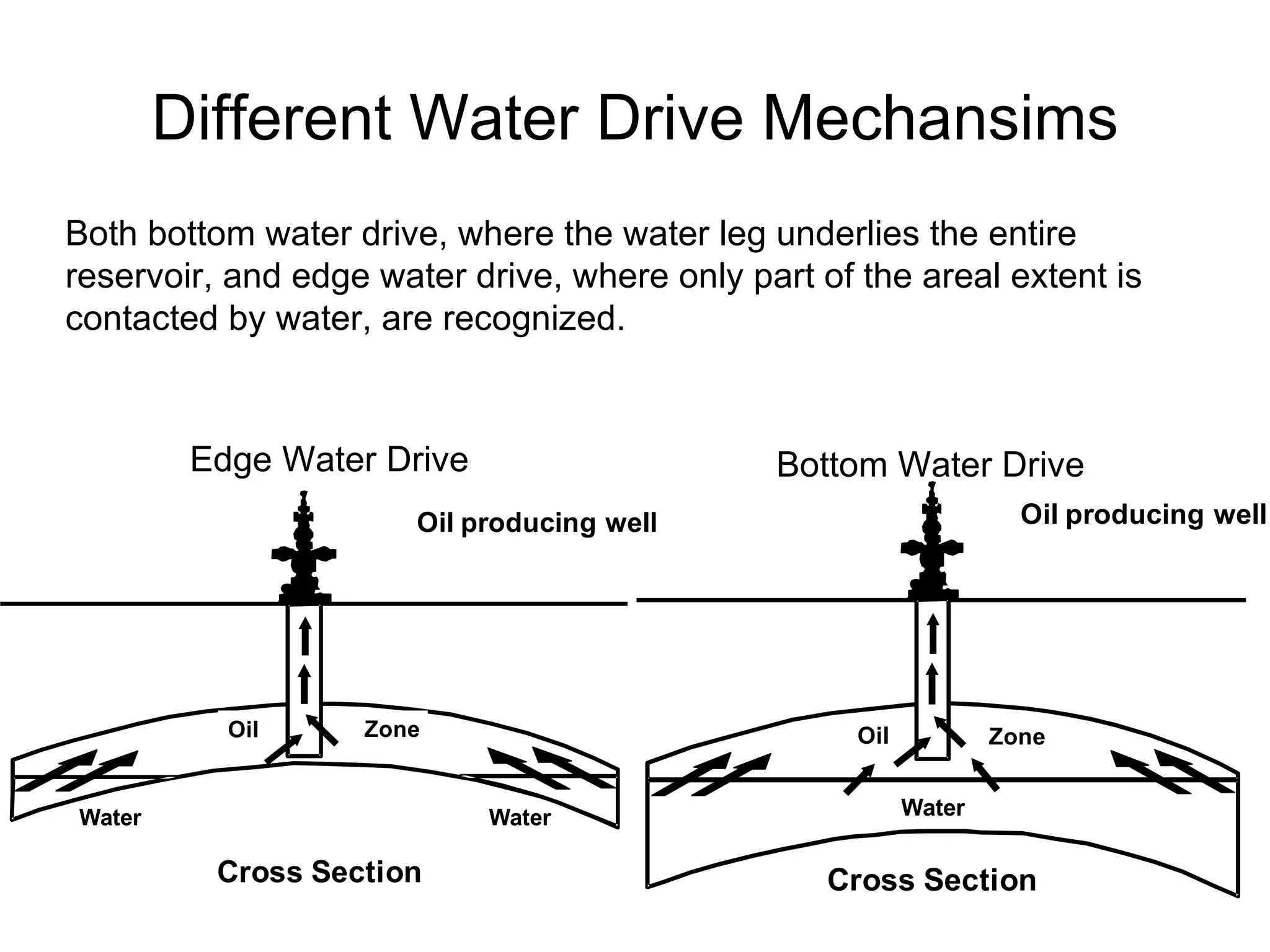
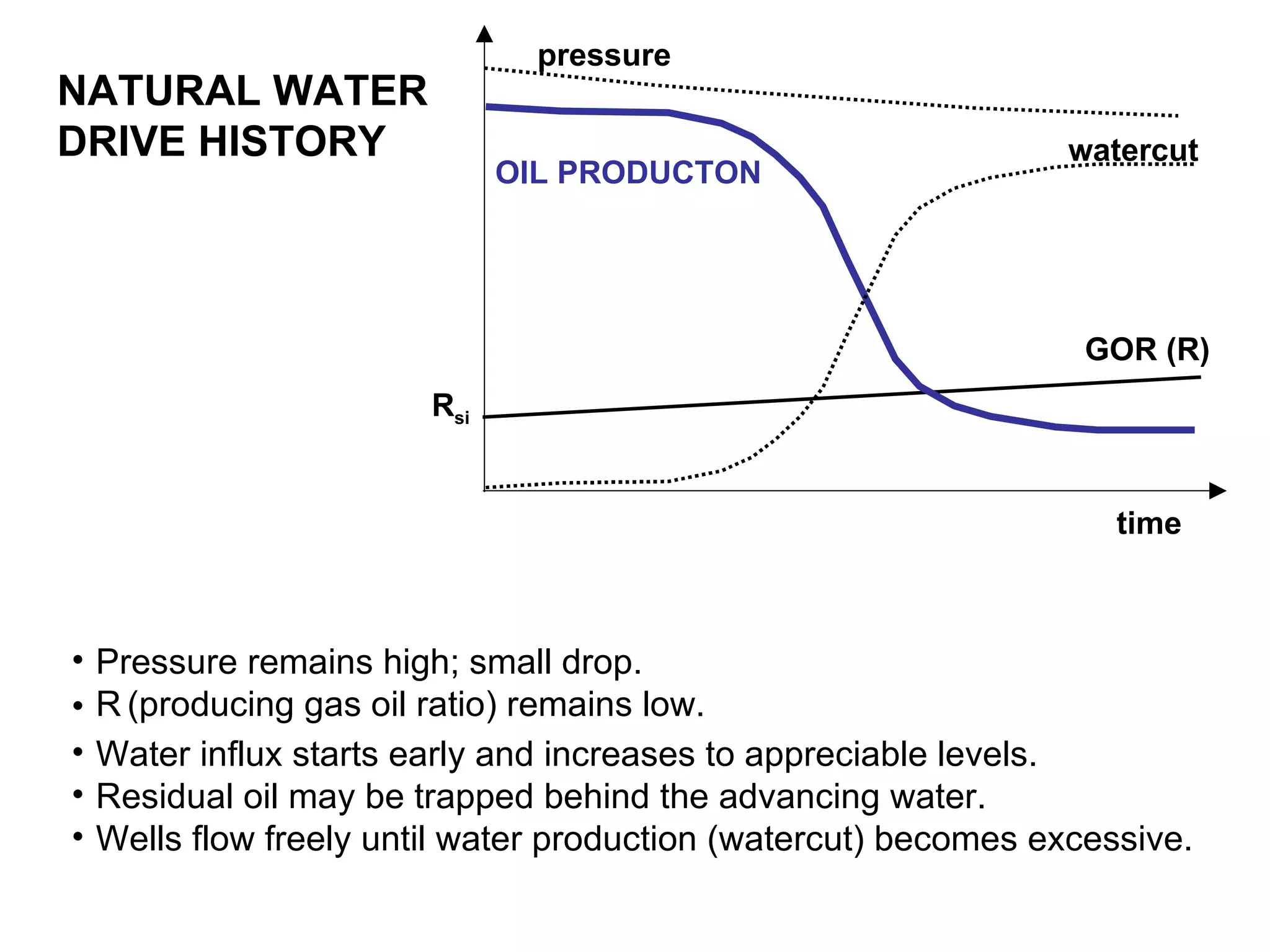
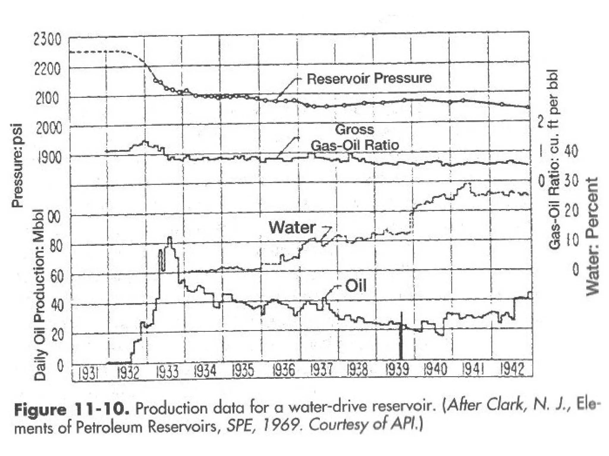
3) Water drive where aquifer water influx provides pressure to displace oil, providing 35-75% oil recovery.
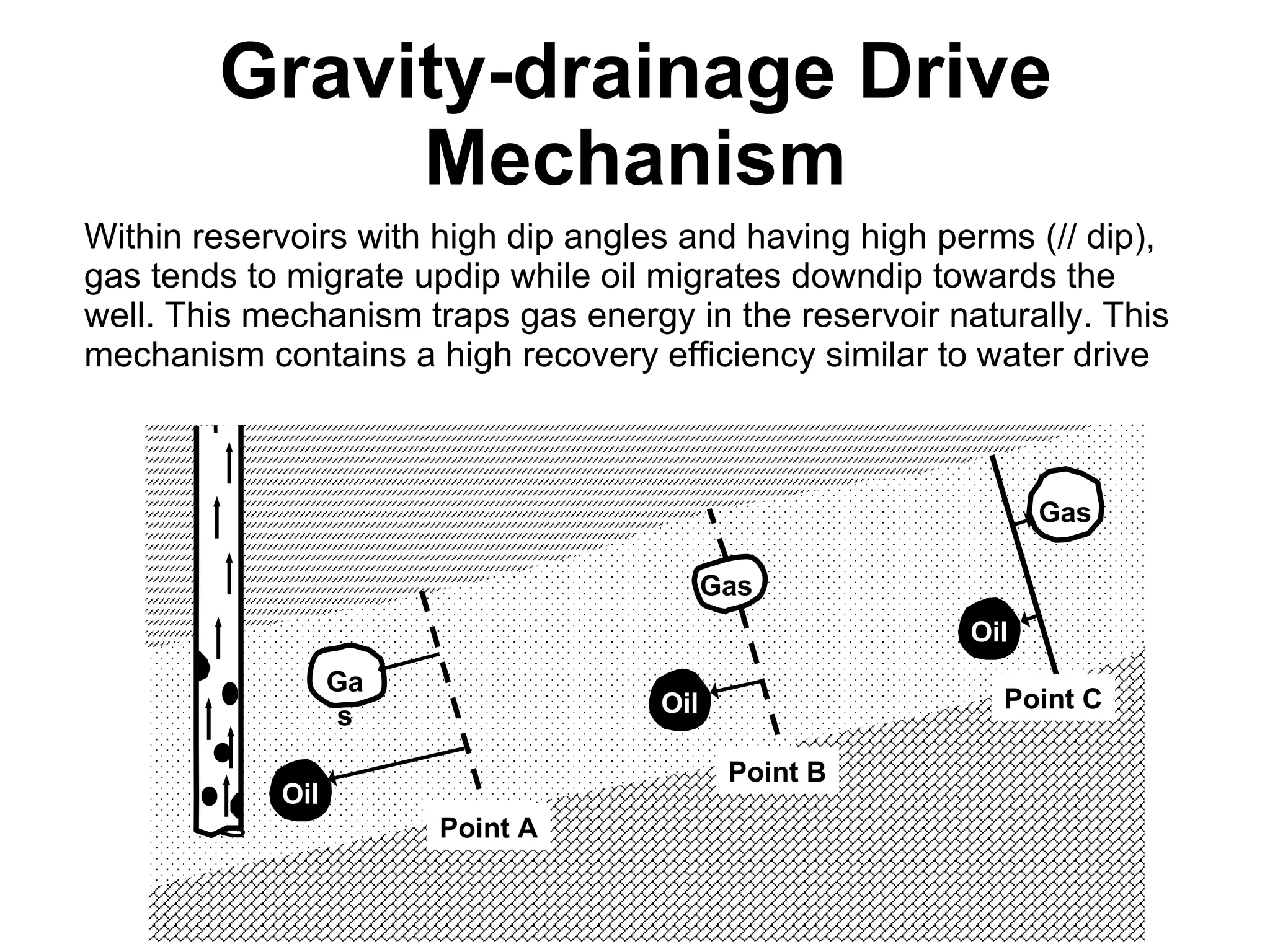
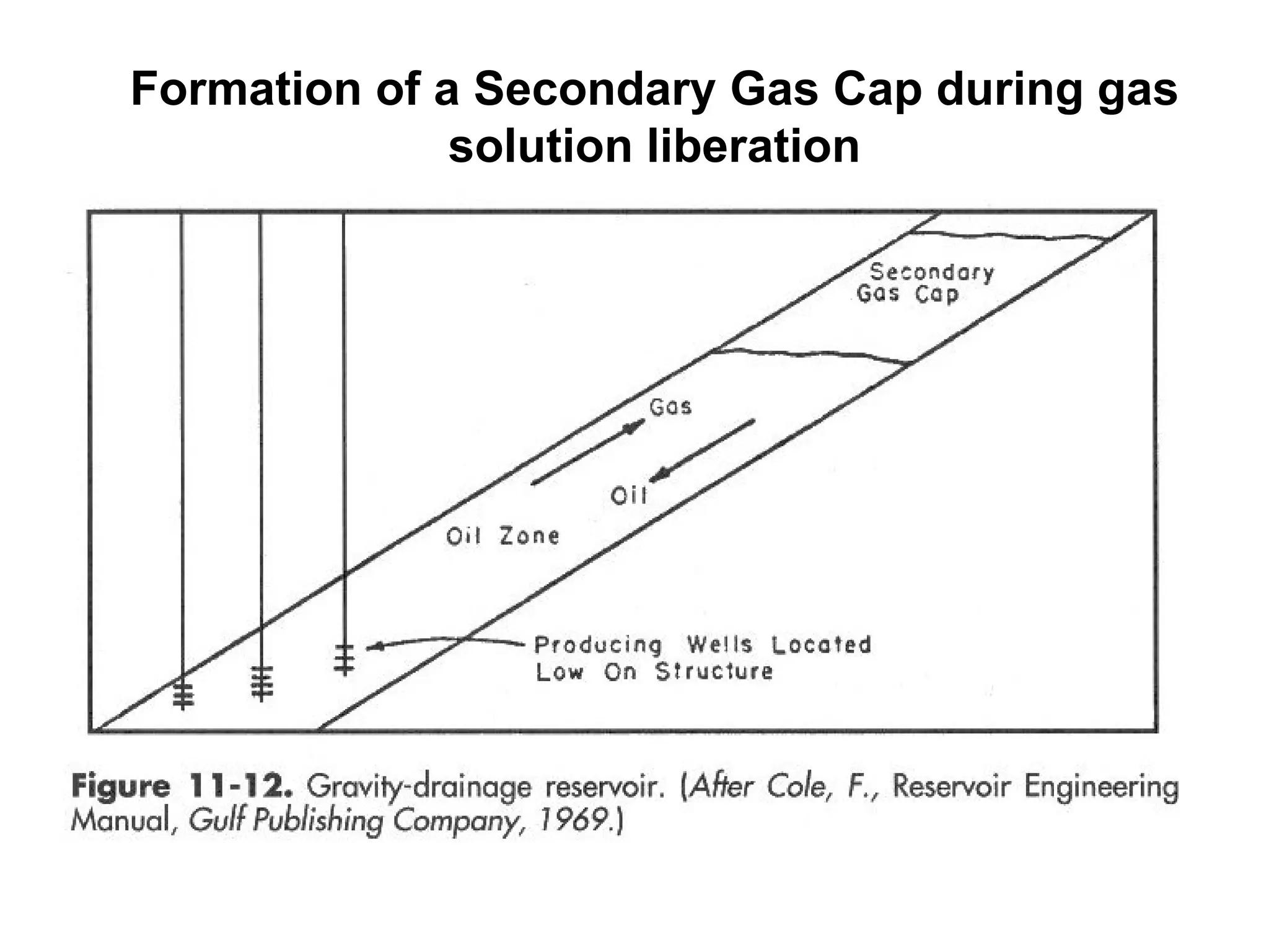
4) Gravity drainage where gas migrates updip and oil downdip in high dip reservoirs.


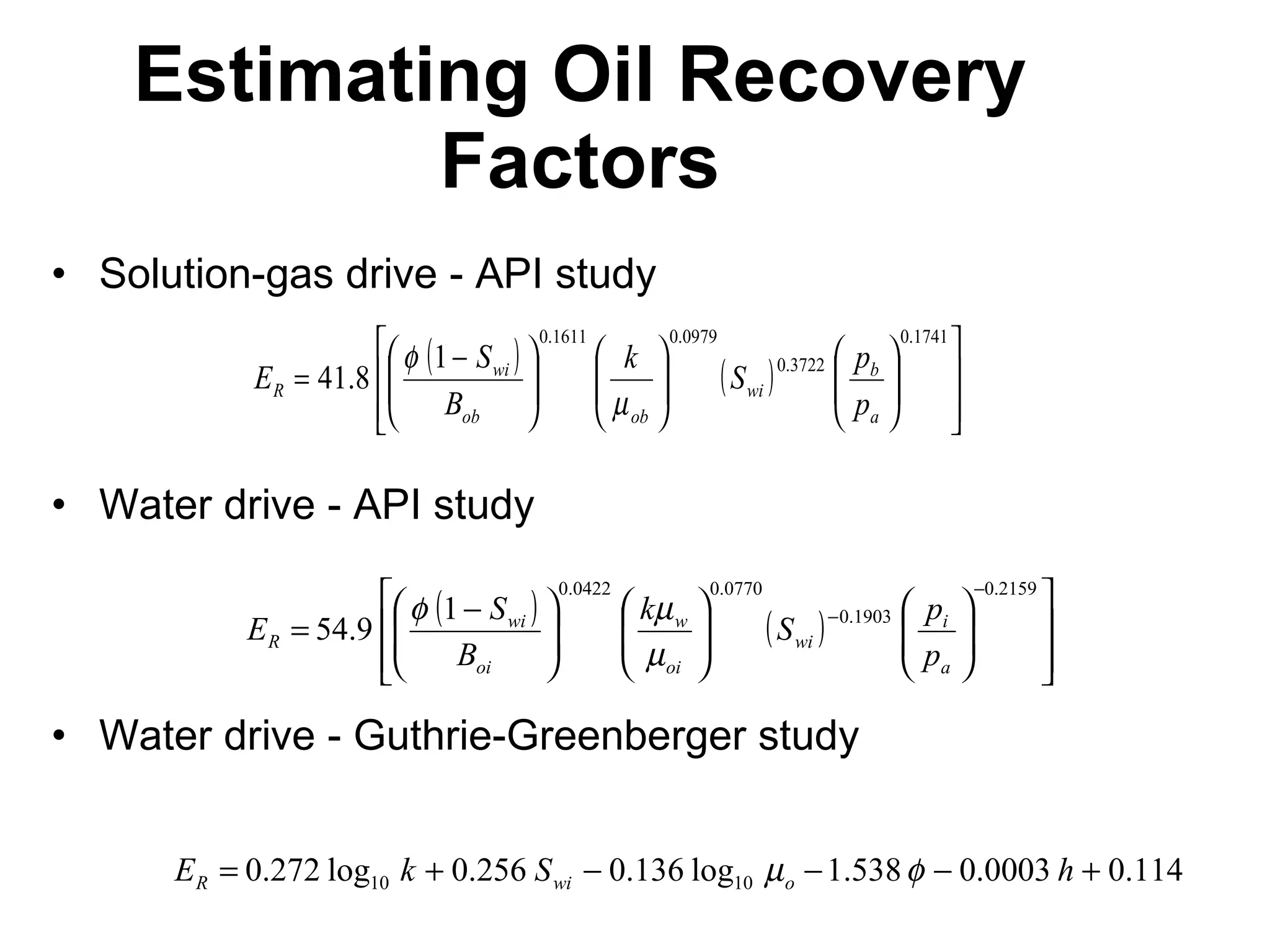
![These correlations work best for sandstone reservoirs . Nomenclature E R = Oil recovery efficiency (recovery factor), [% (for API study); fraction (for G-G study)] = Reservoir porosity, fraction S wi = Interstitial water saturation, fraction B ob = Formation volume factor of oil at bubblepoint, RB/STB k = Reservoir permeability, [darcy (for API study); md (For G-G study)] ob = Oil viscosity at bubblepoint pressure, cp p b = Bubblepoint pressure of oil, psig p a = Abandonment reservoir pressure, psig](https://image.slidesharecdn.com/4-1reservoirdrivemechanisms-111018210600-phpapp02/75/4-1-reservoir-drive_mechanisms-26-2048.jpg)