Downloaded 481 times

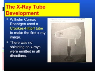
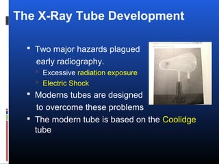
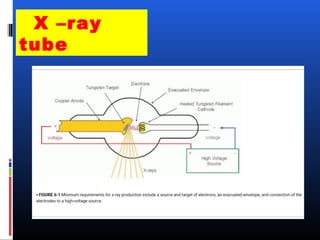
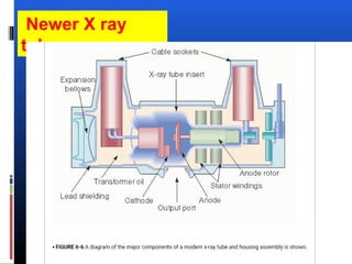
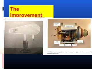
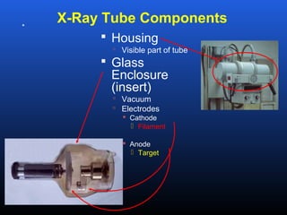
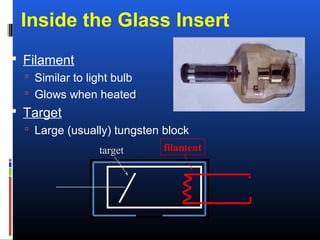
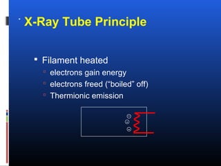
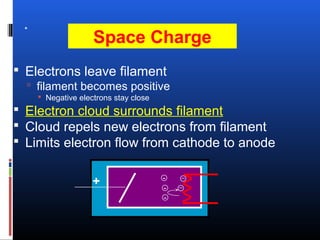
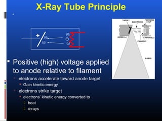
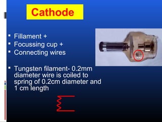

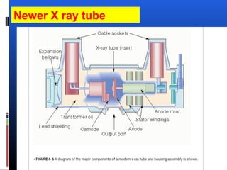


Wilhelm Conrad Roentgen used a Crookes-Hittorf tube to produce the first x-rays in 1895. Early x-ray tubes had no shielding and emitted radiation in all directions, posing major hazards. Modern tubes are designed with shielding and safety features to overcome these problems. Key components of x-ray tubes include the cathode, which emits electrons via thermionic emission, the anode target, which converts the electrons' kinetic energy to x-rays, and various designs like rotating anodes to dissipate heat and improve performance.


