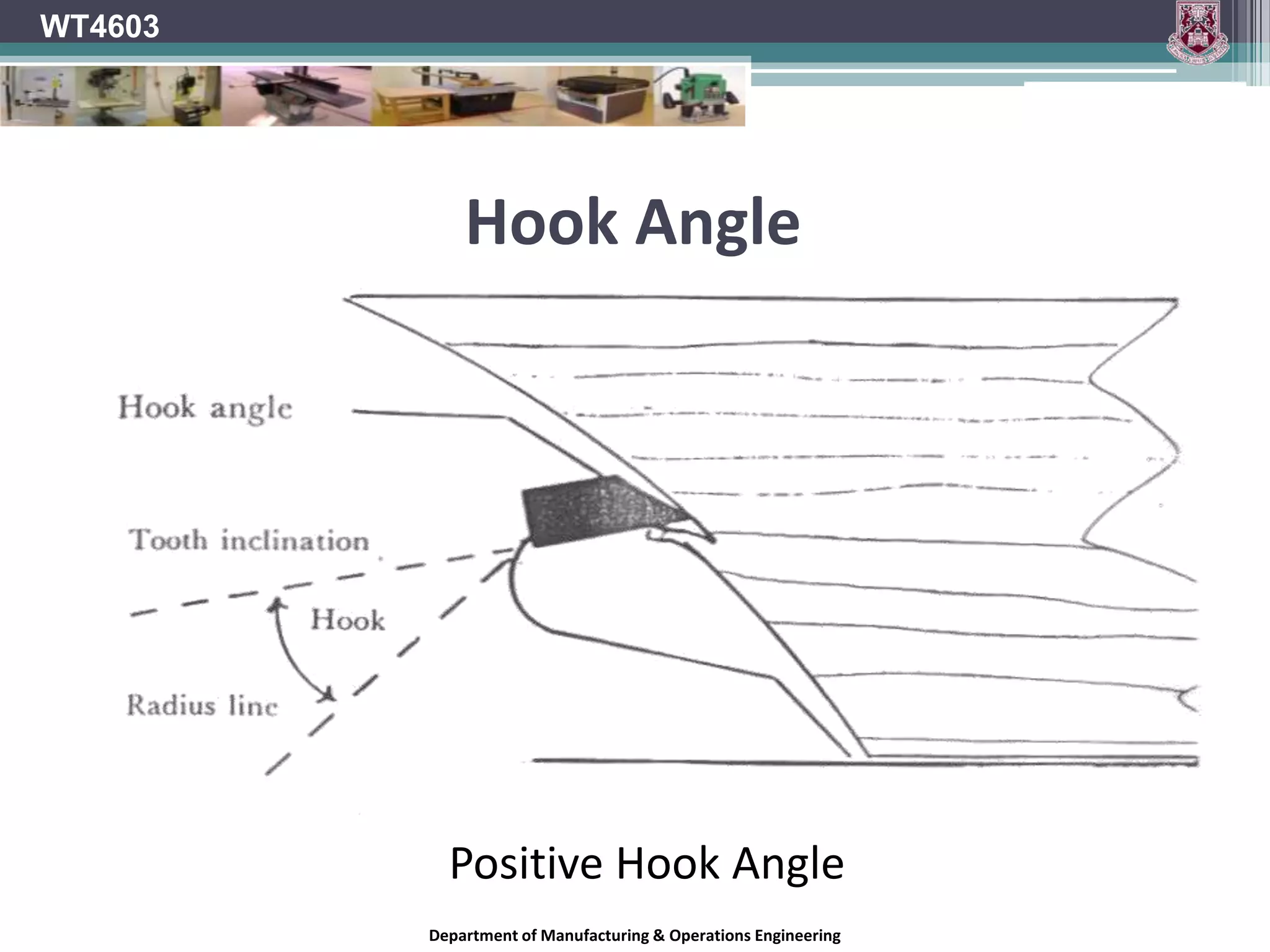
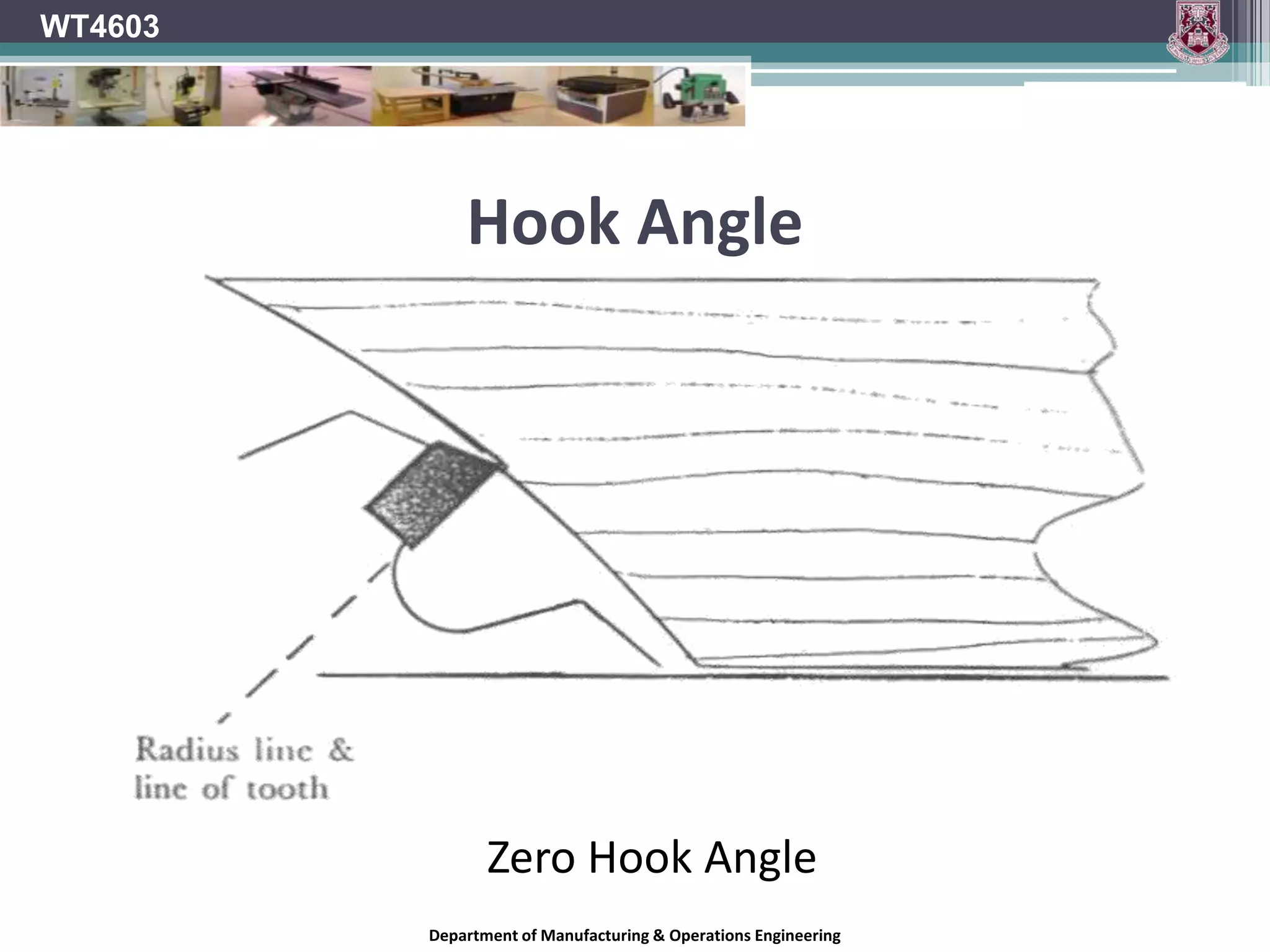
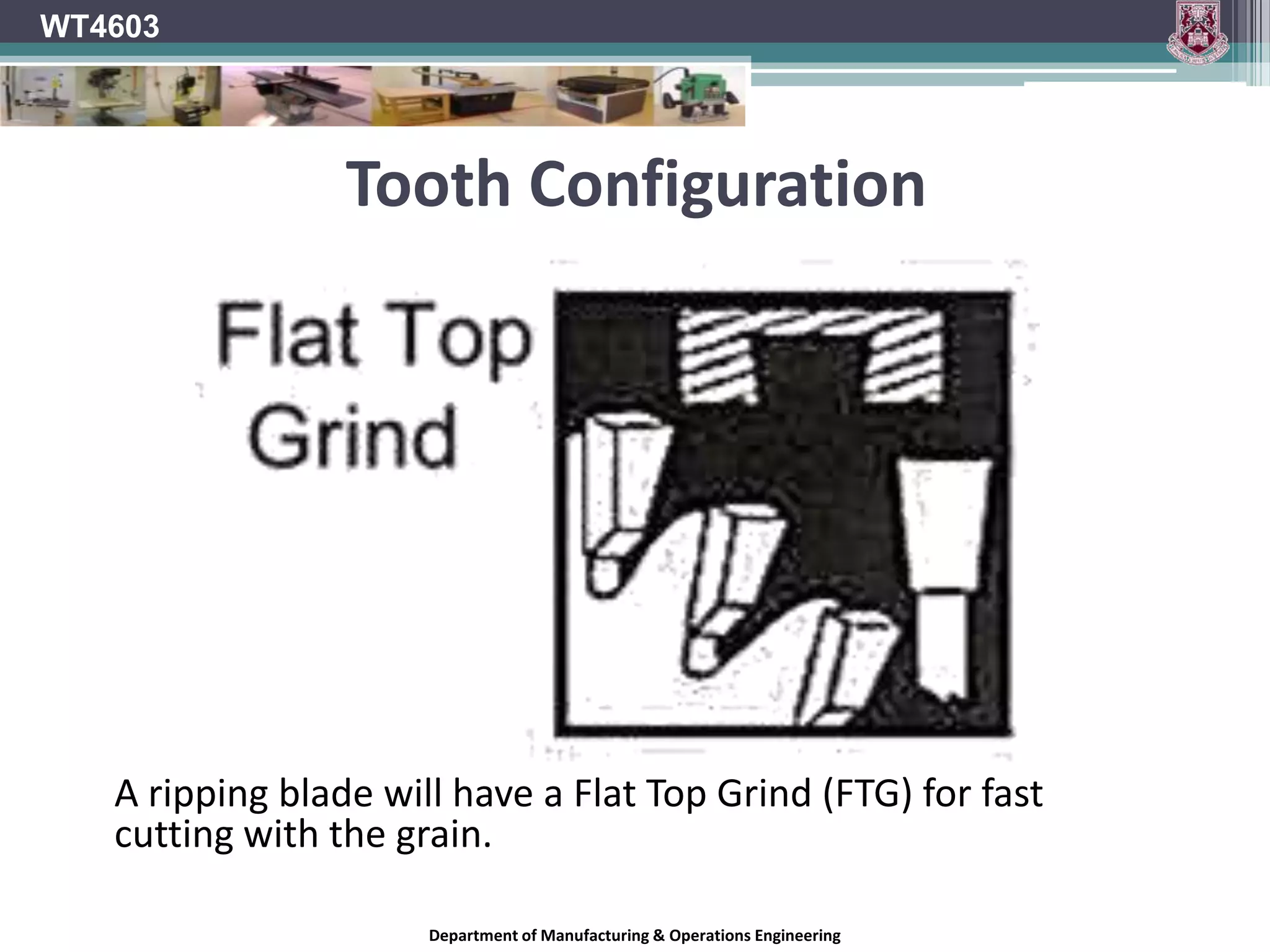
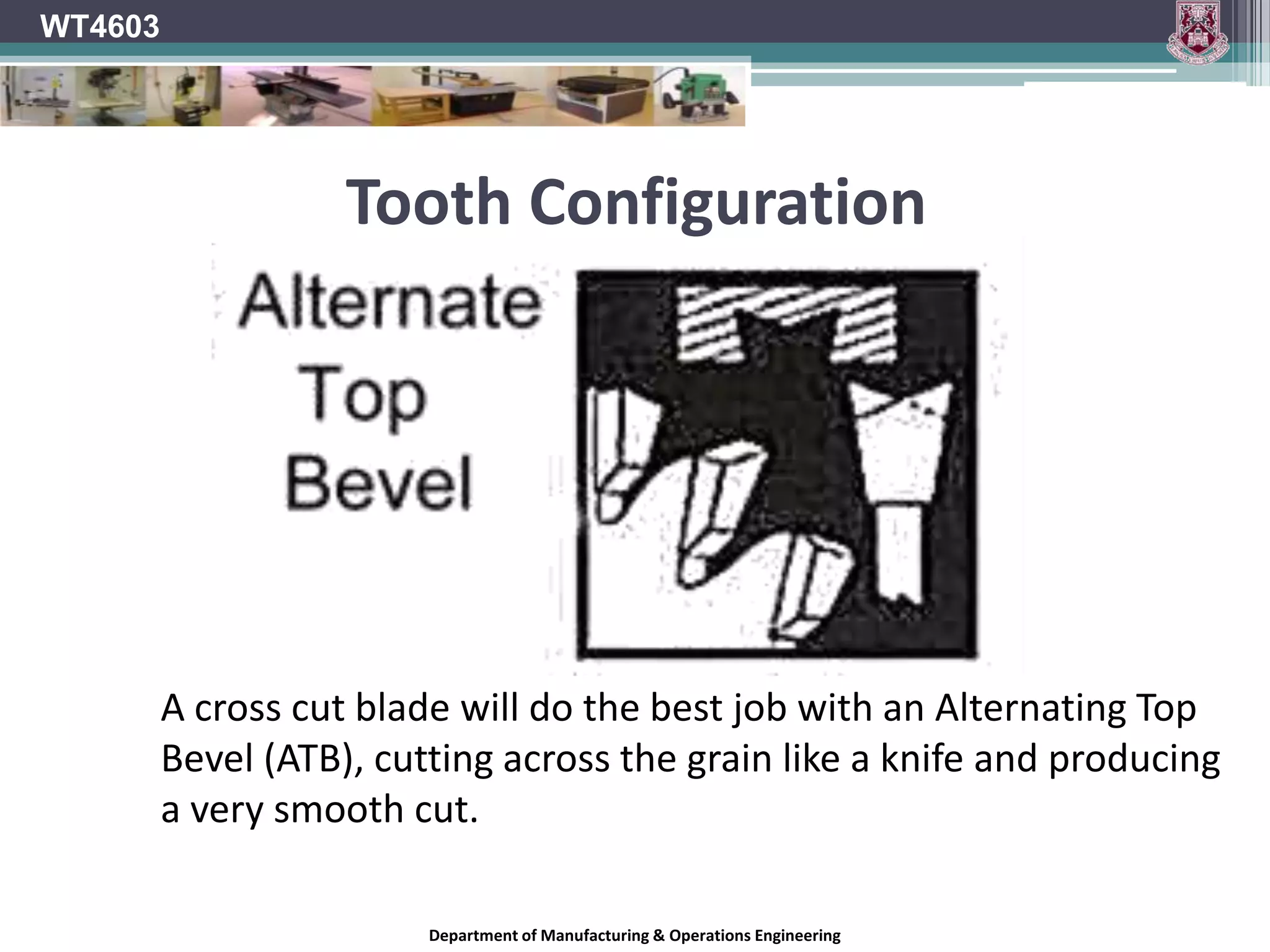
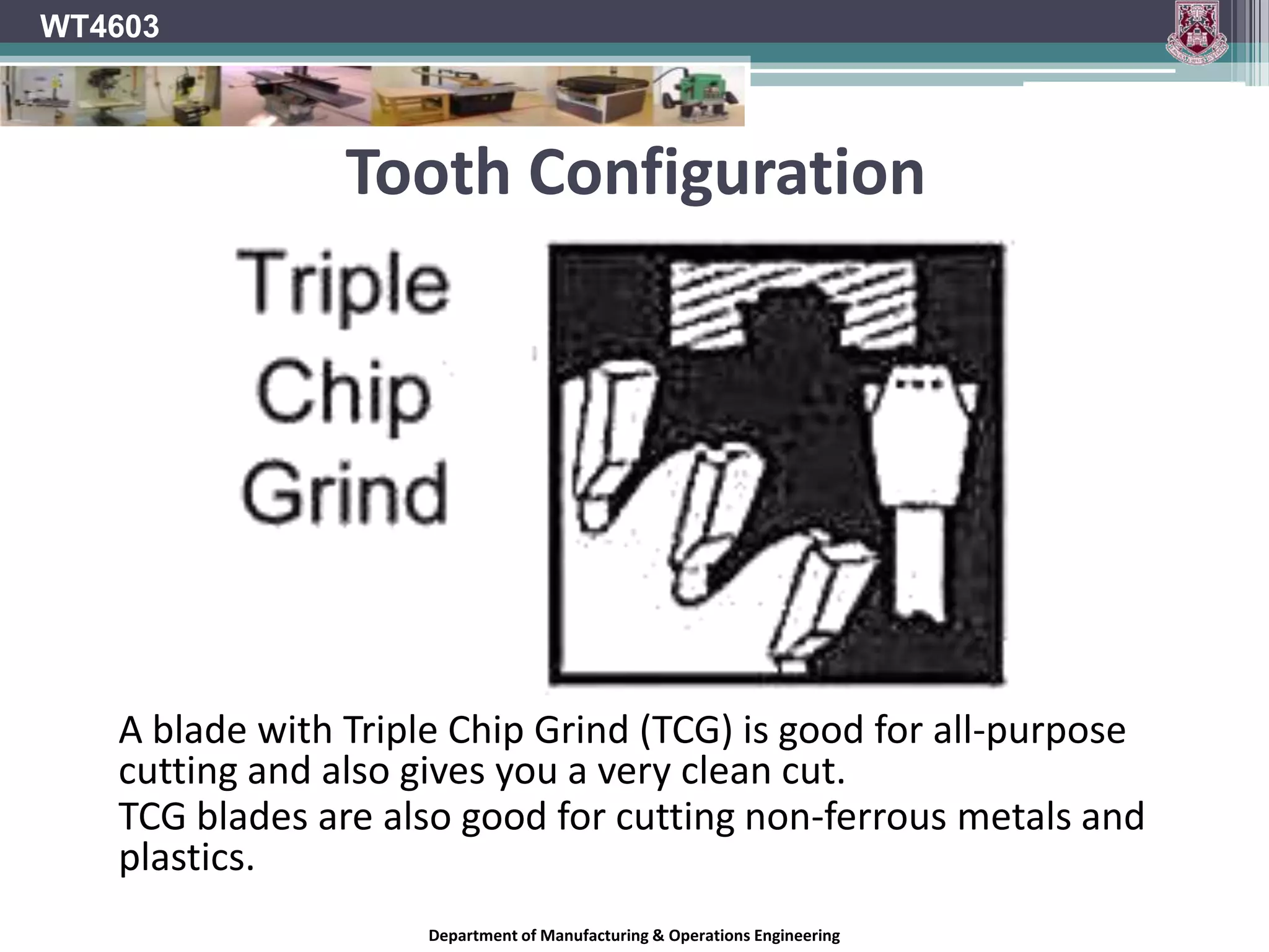
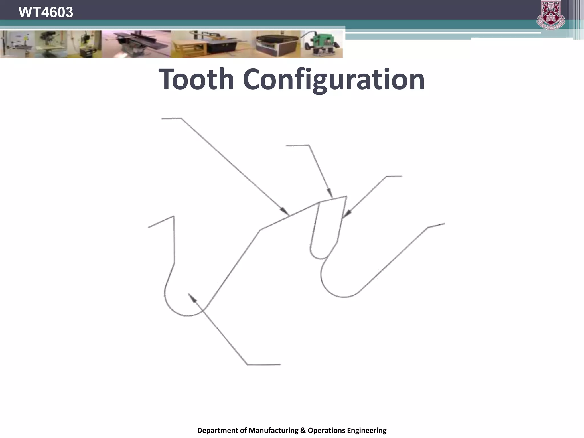
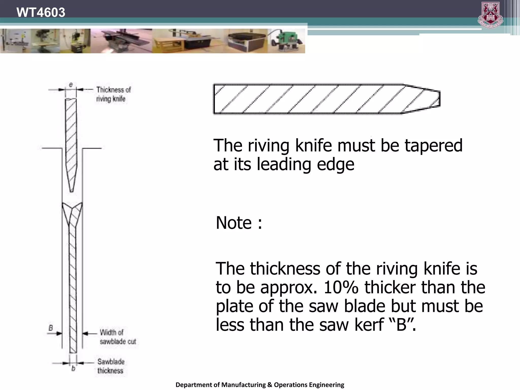
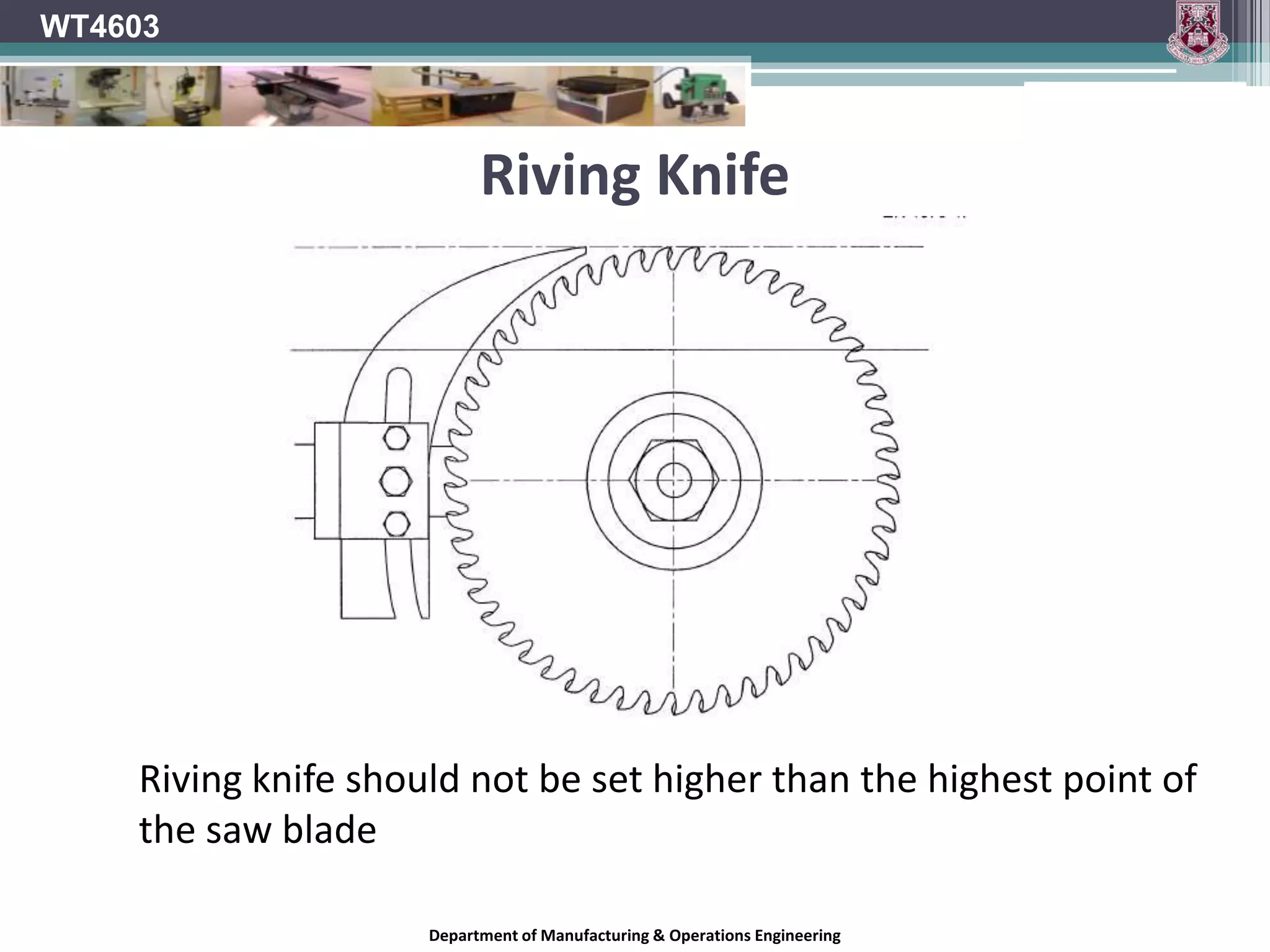
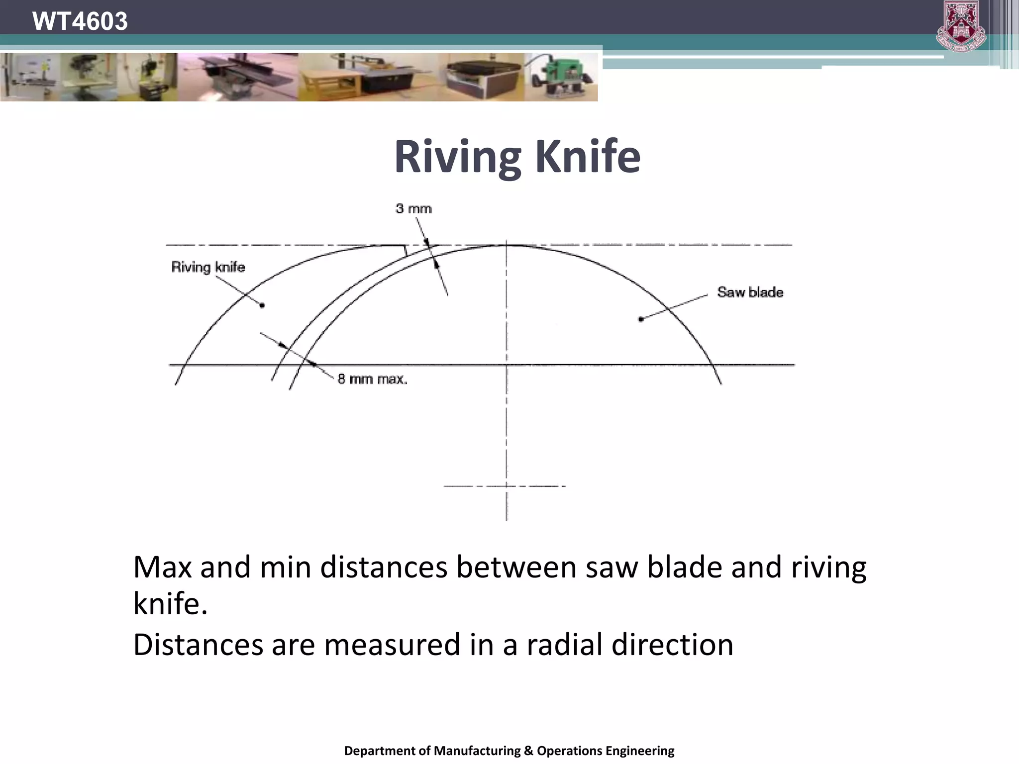
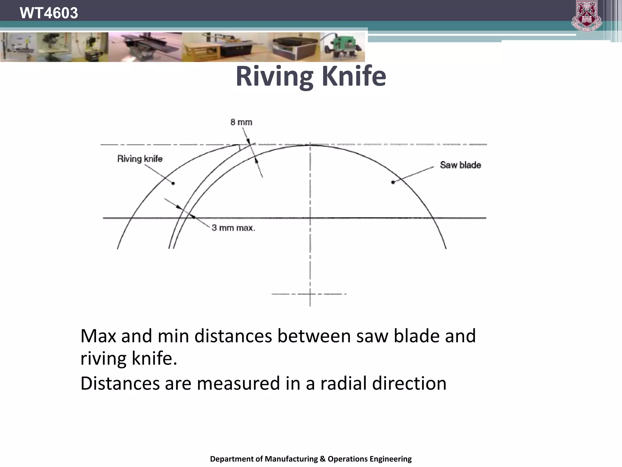
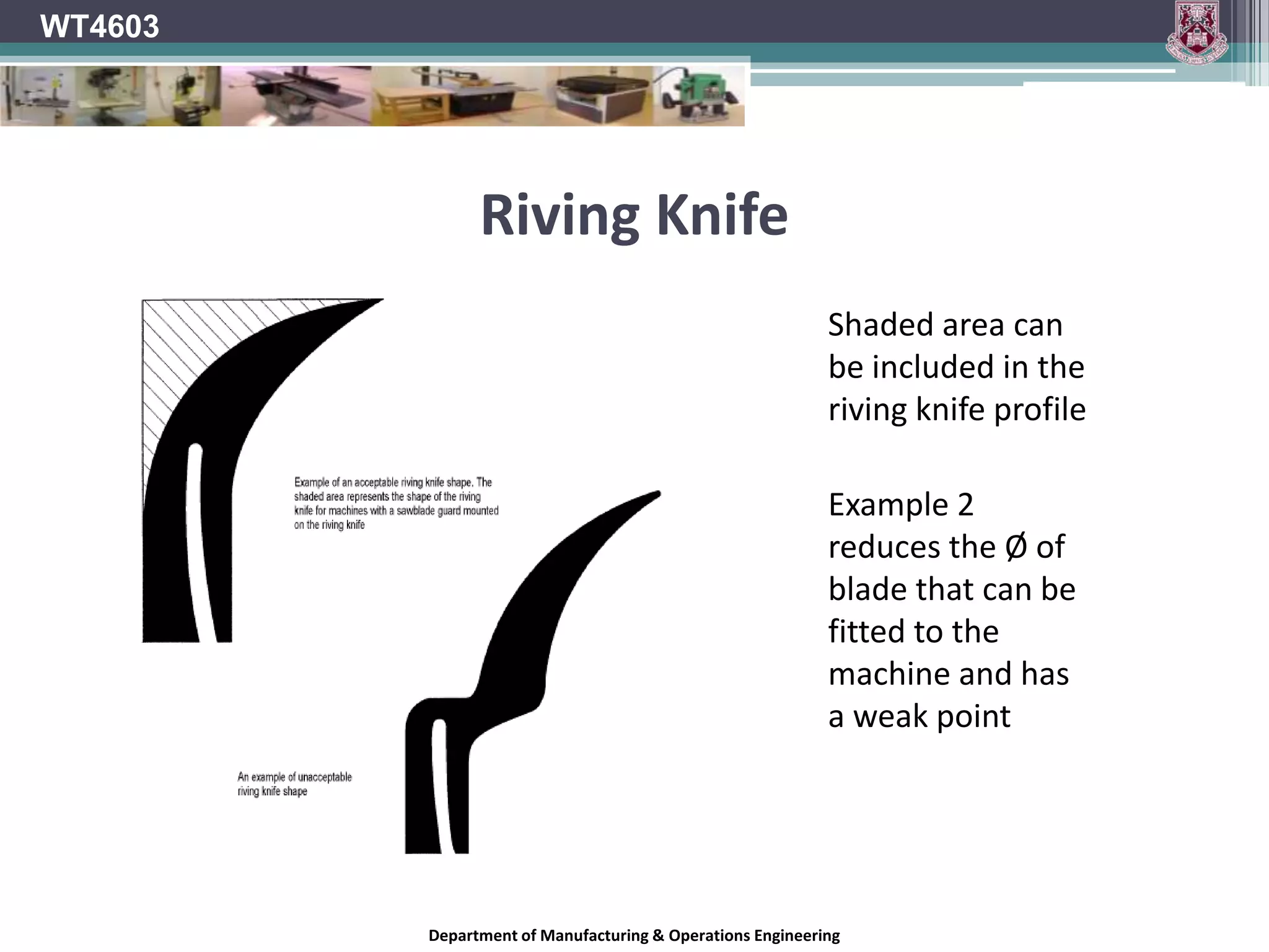
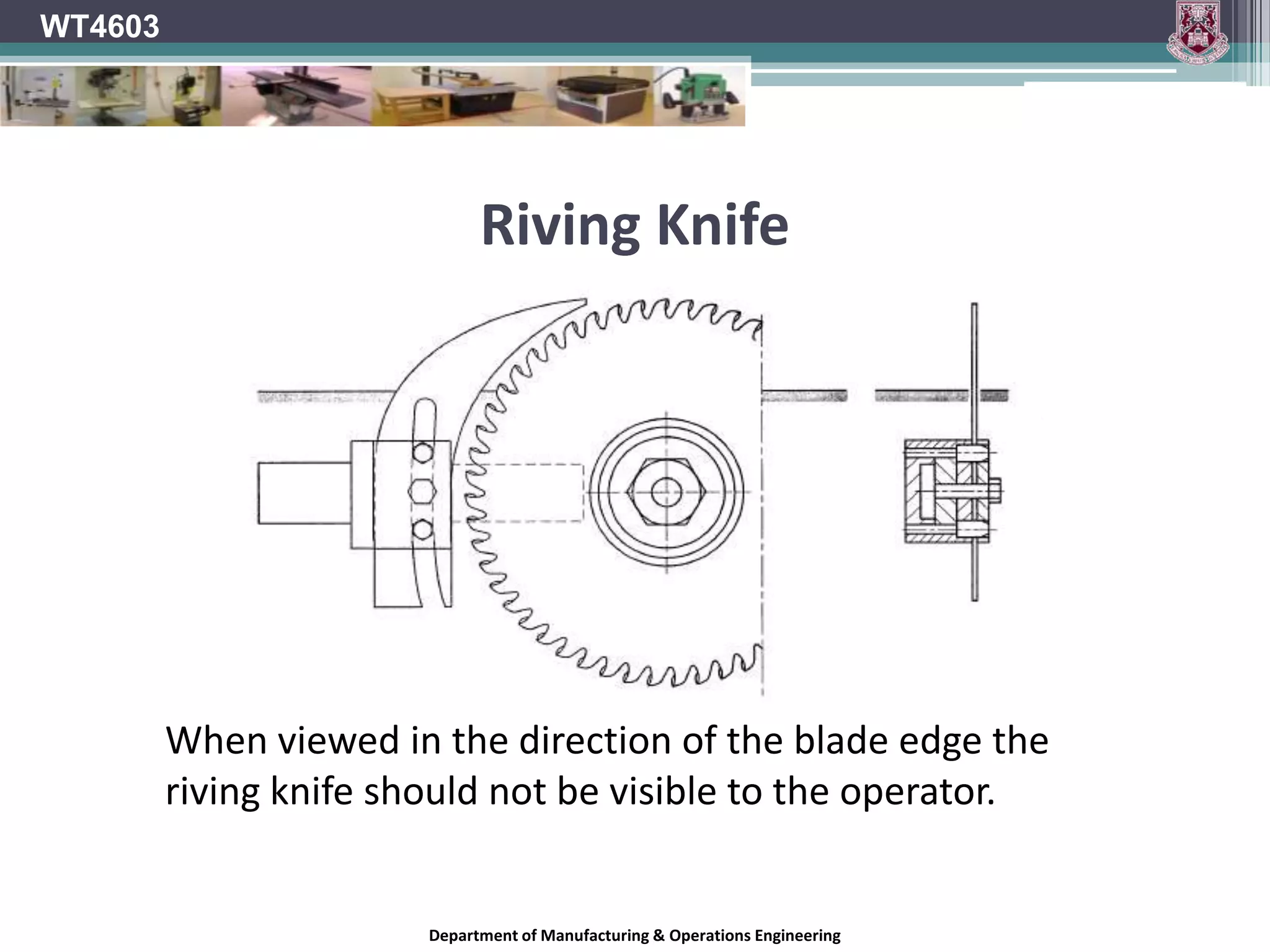
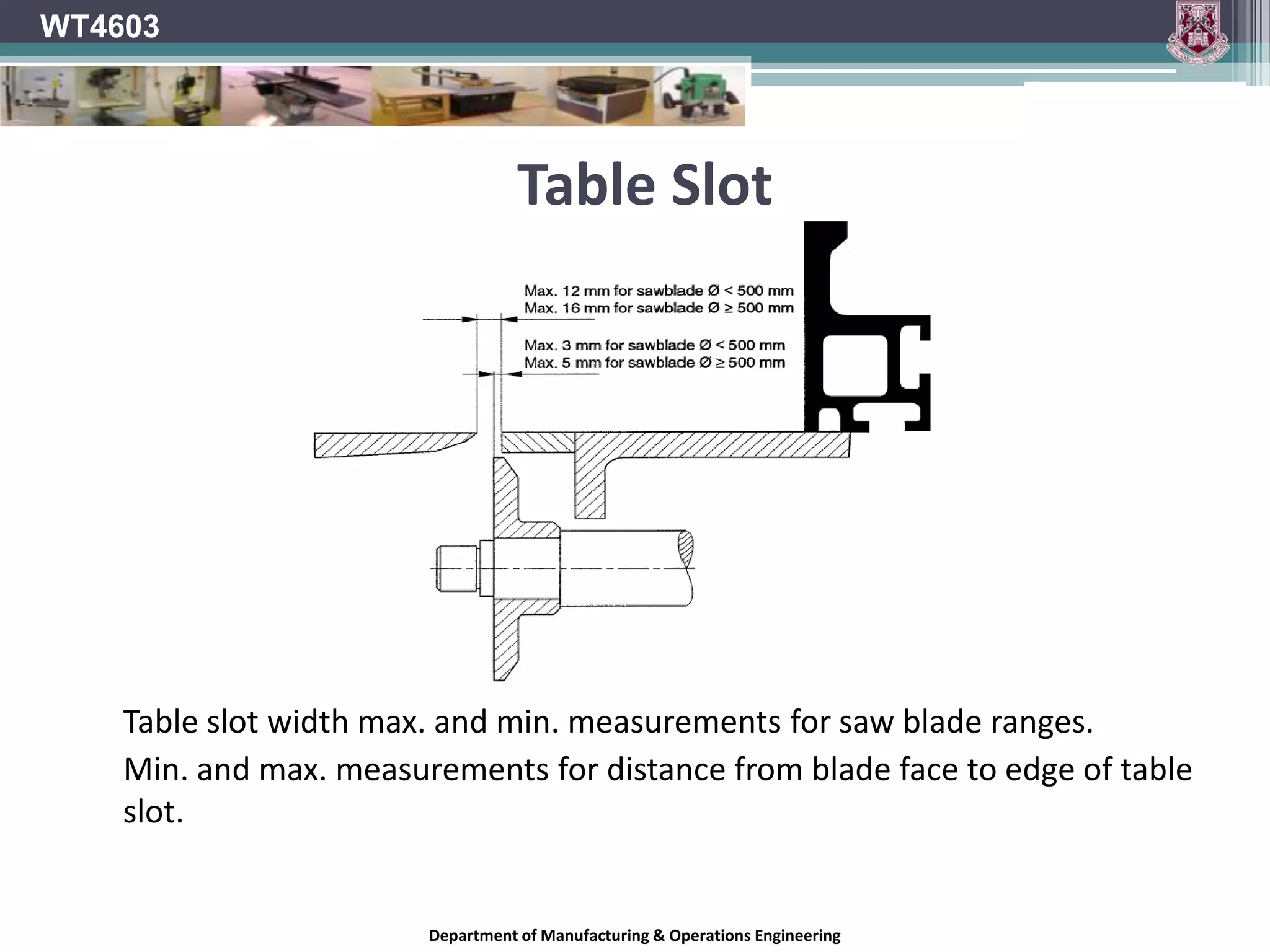
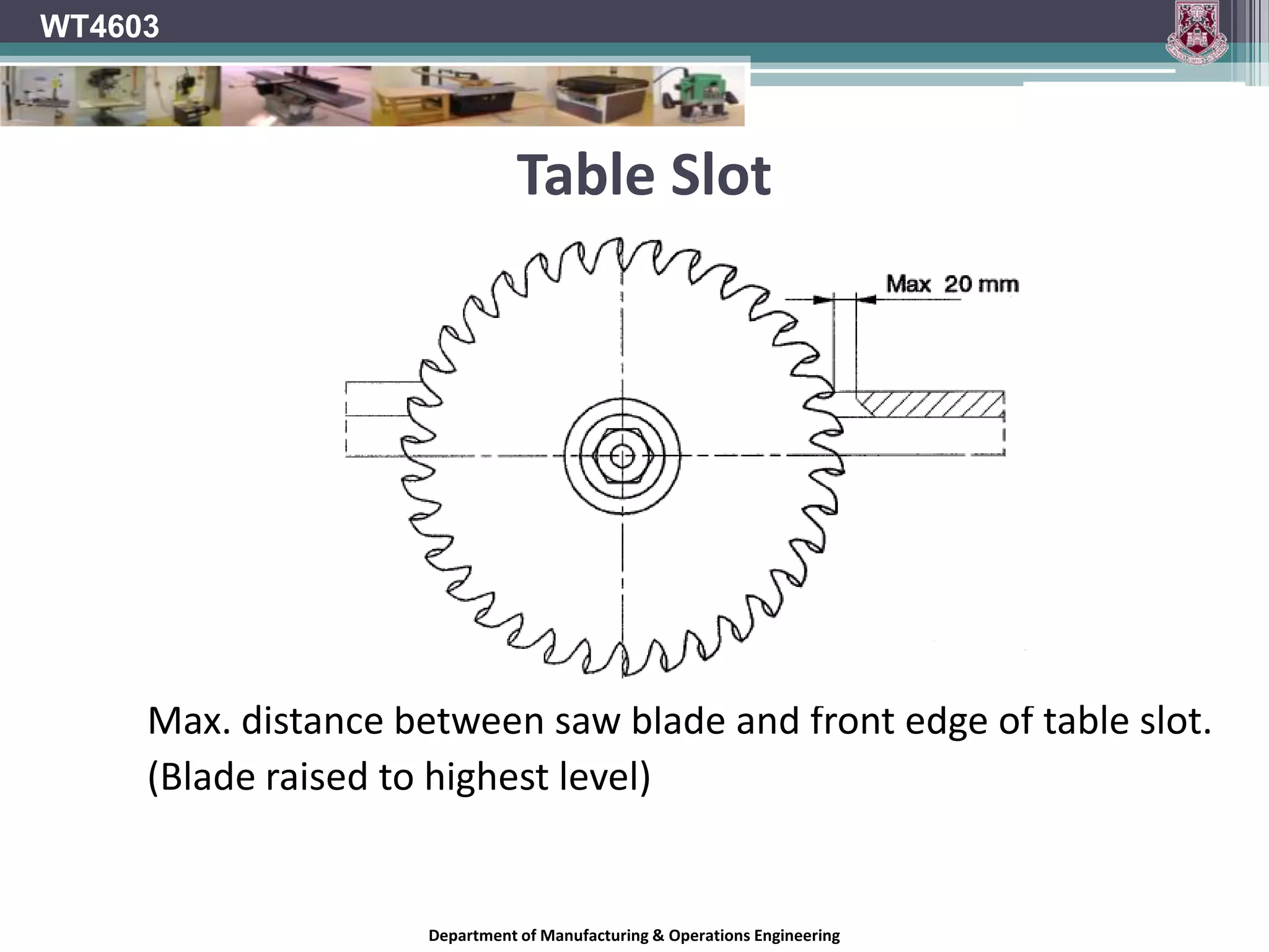
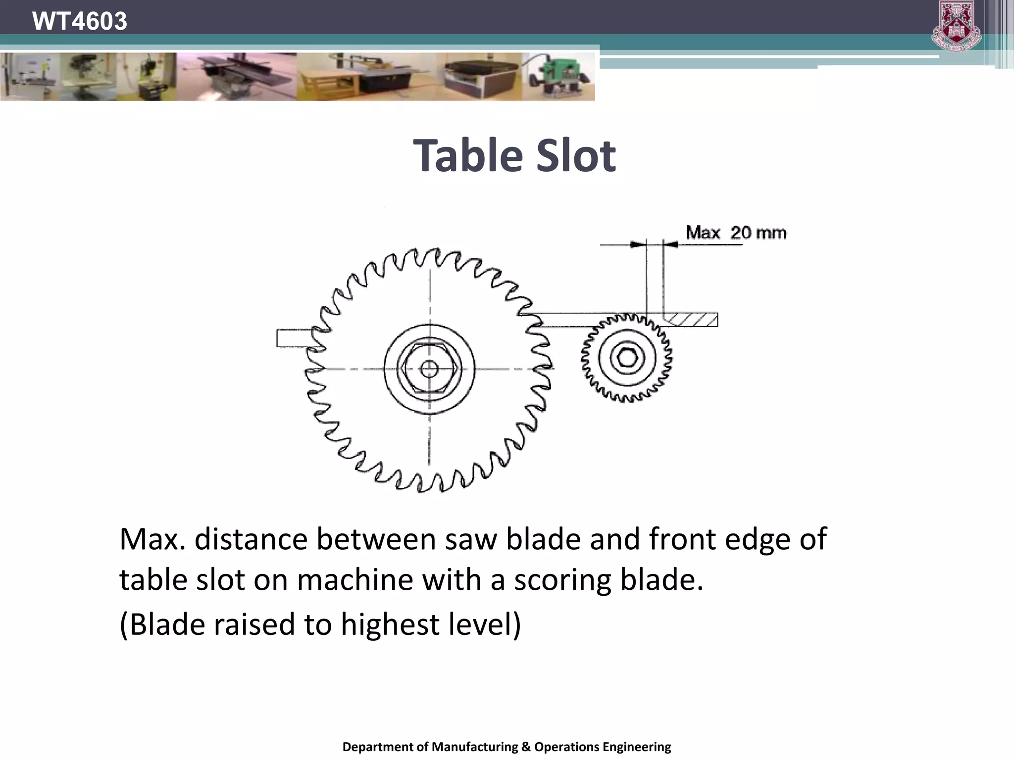
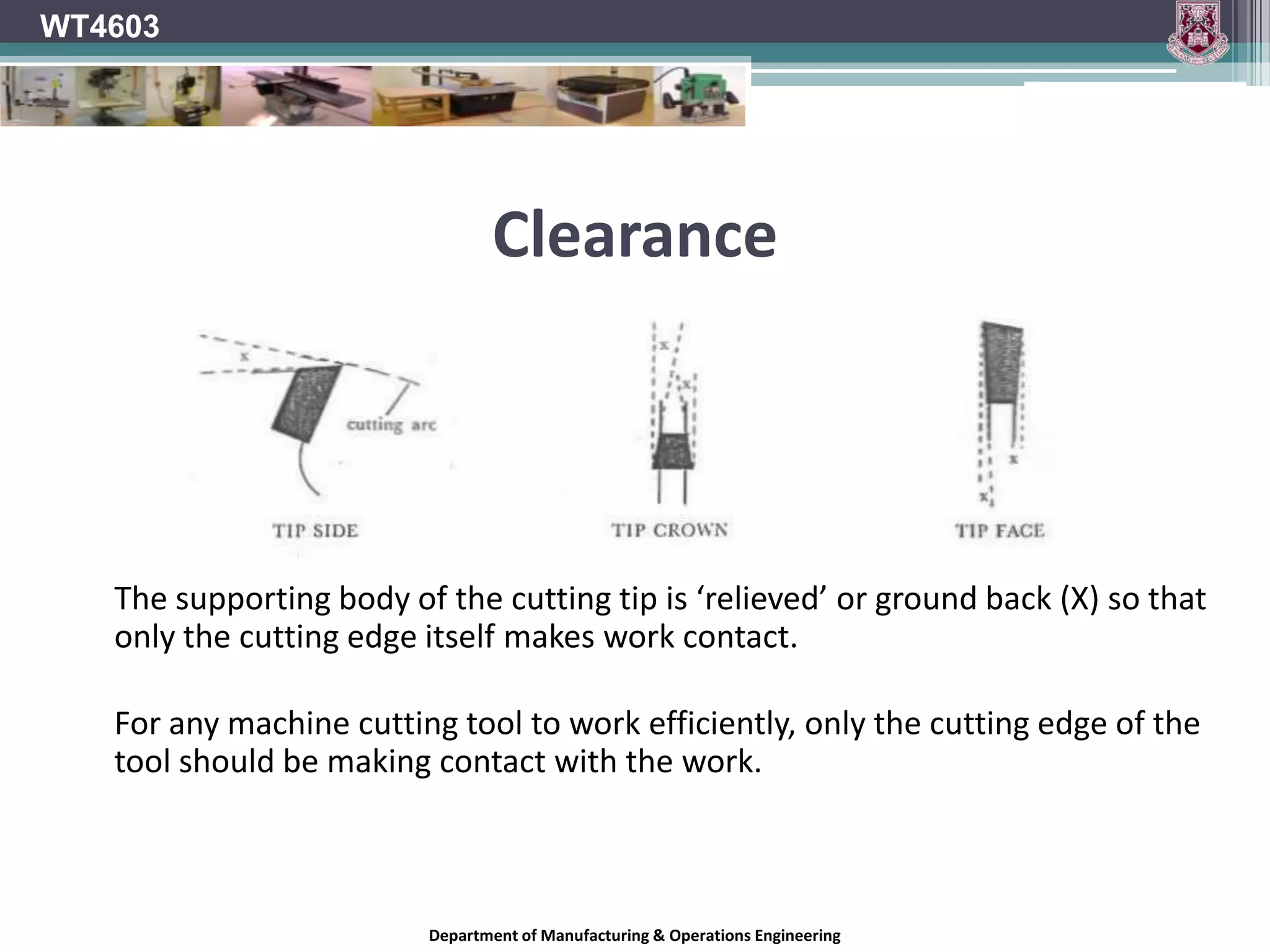
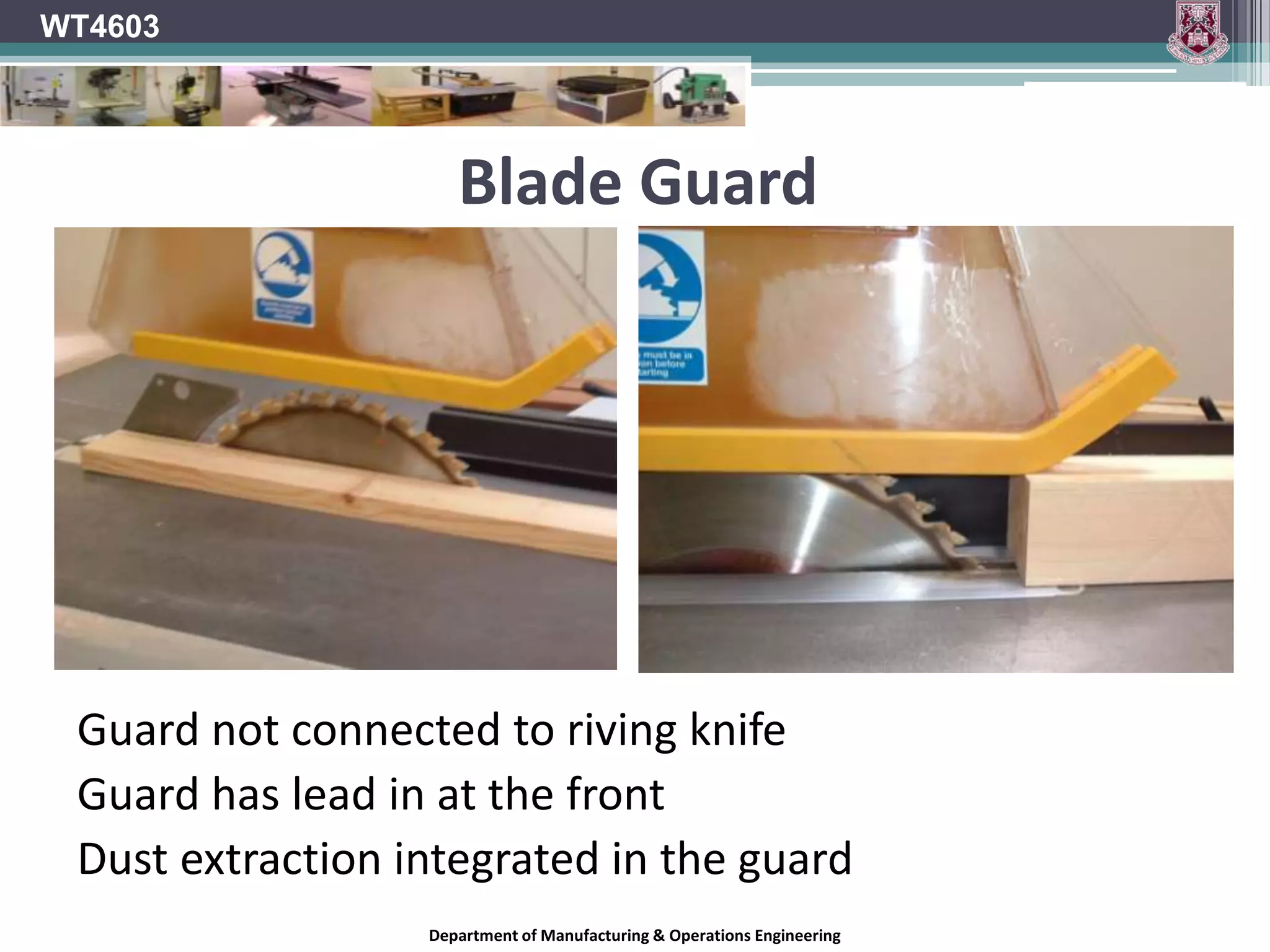
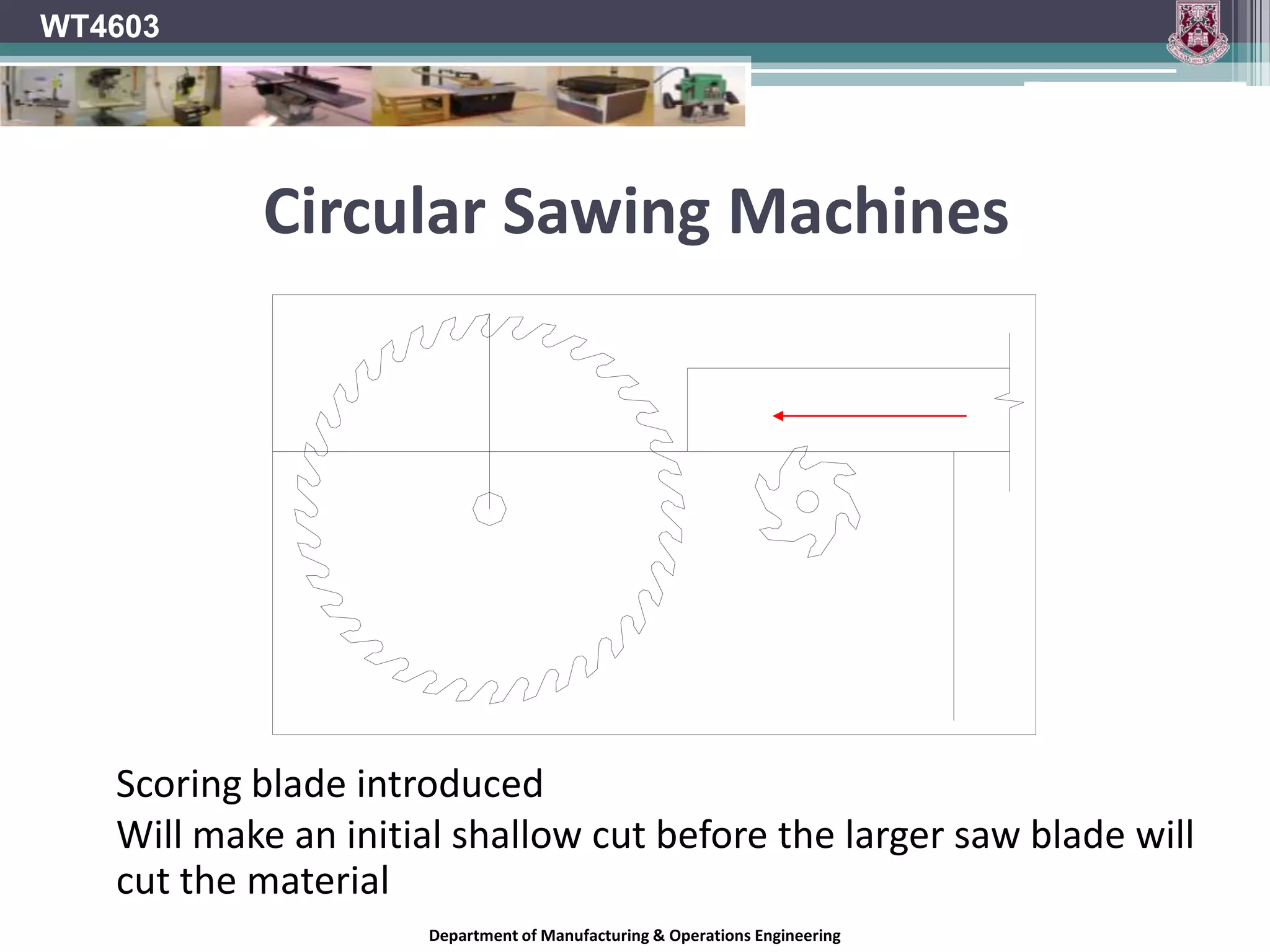
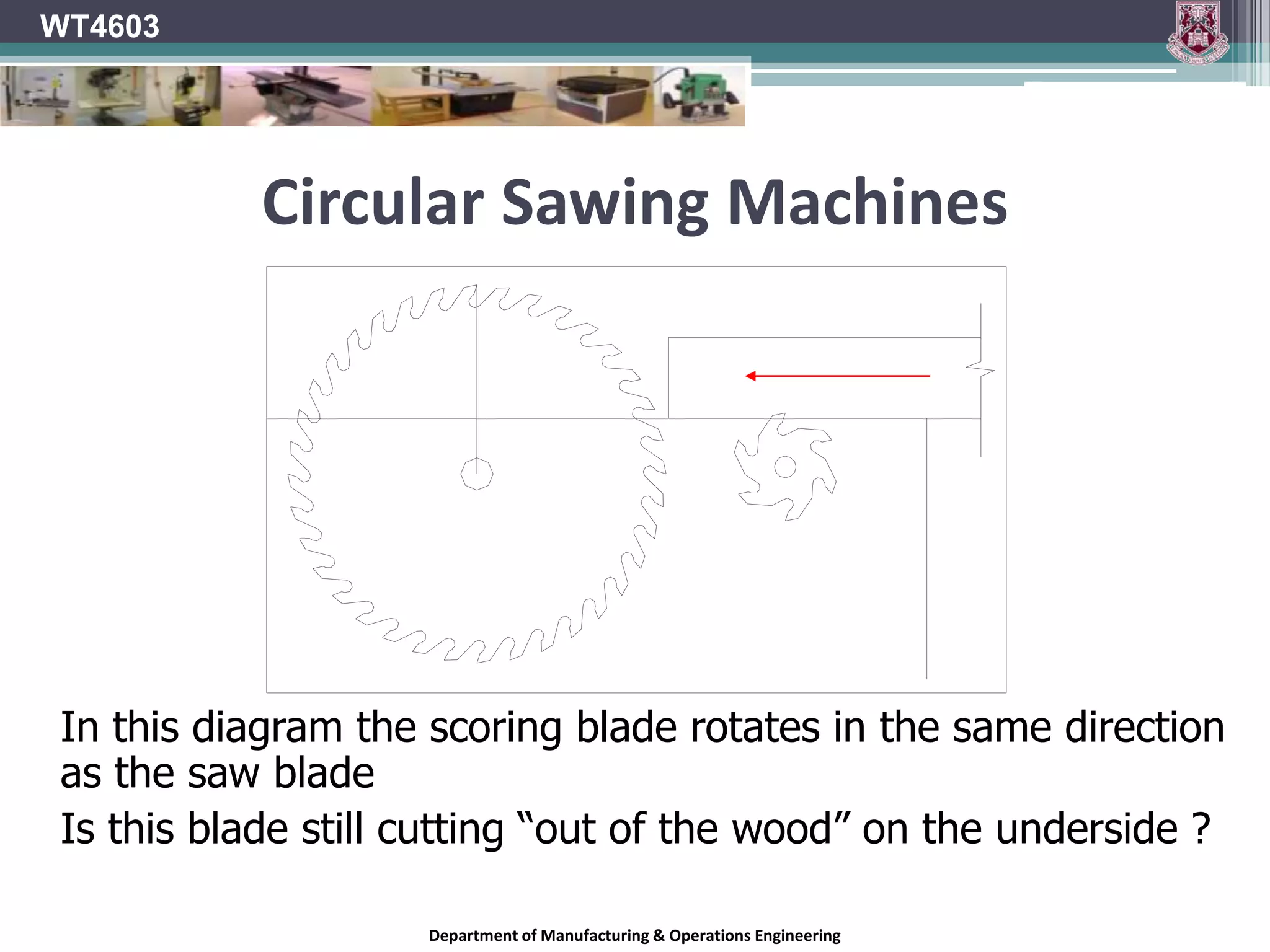
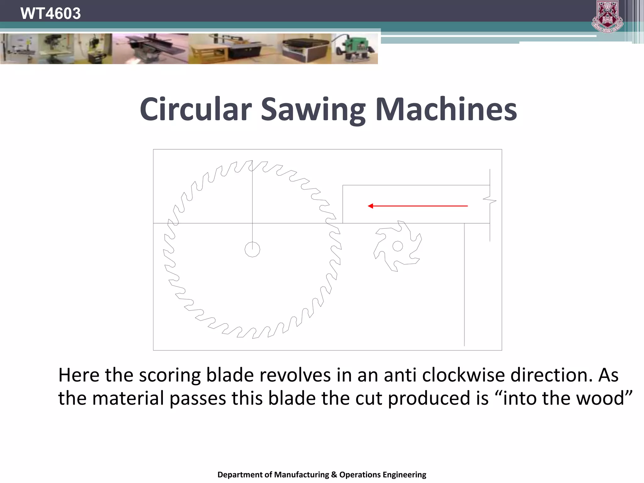
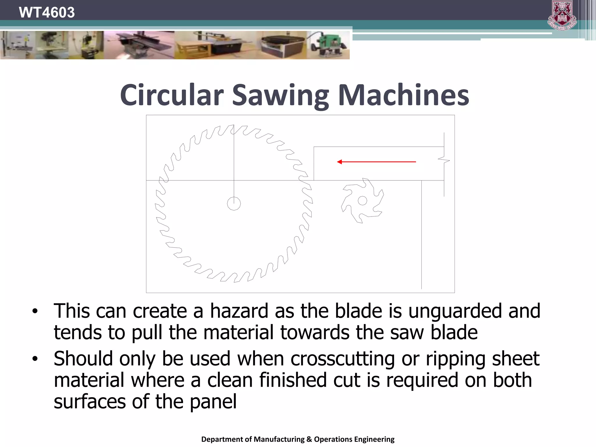
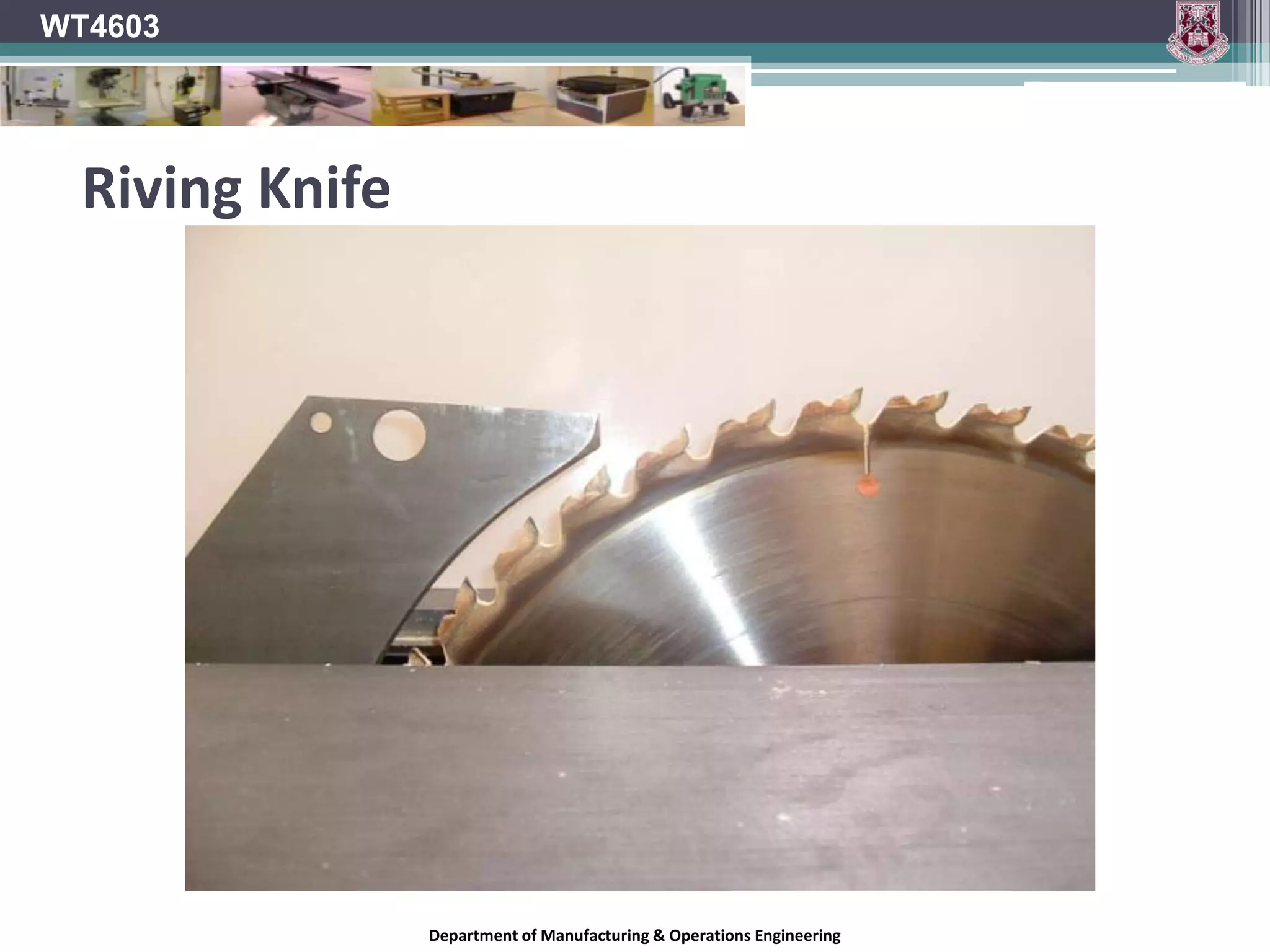
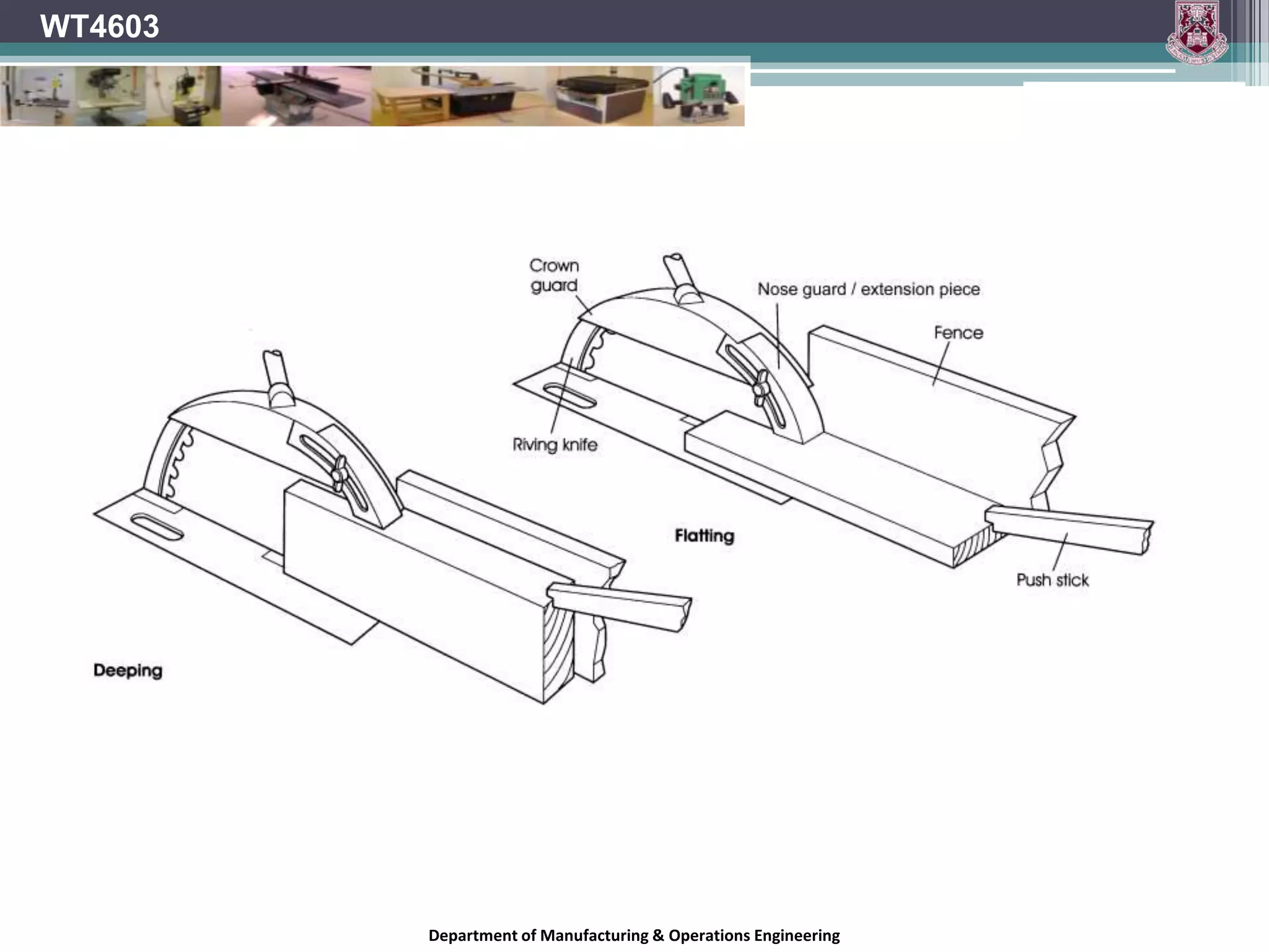
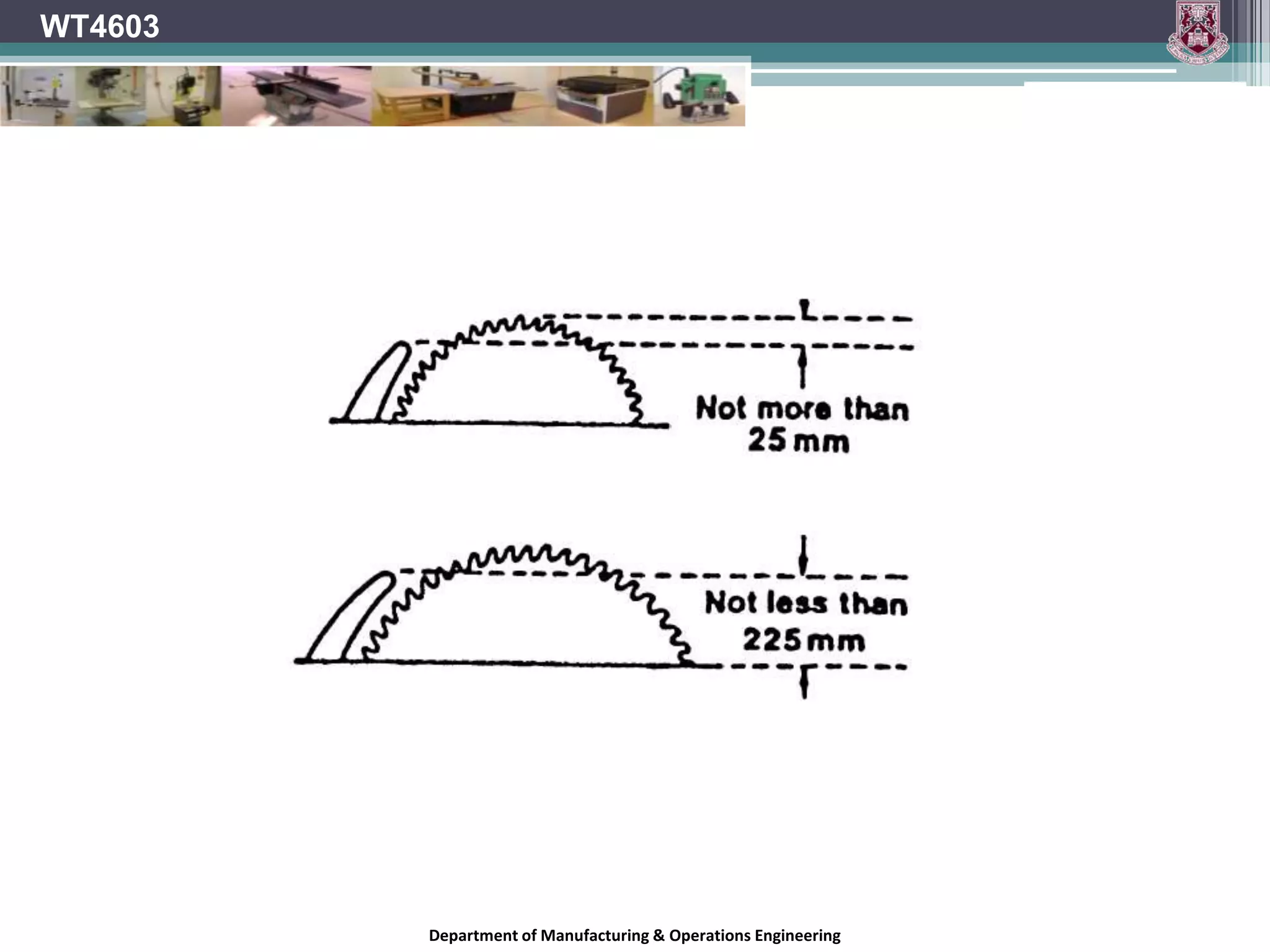
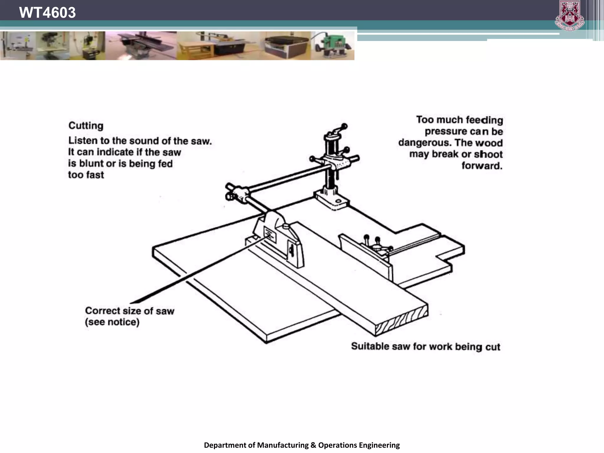
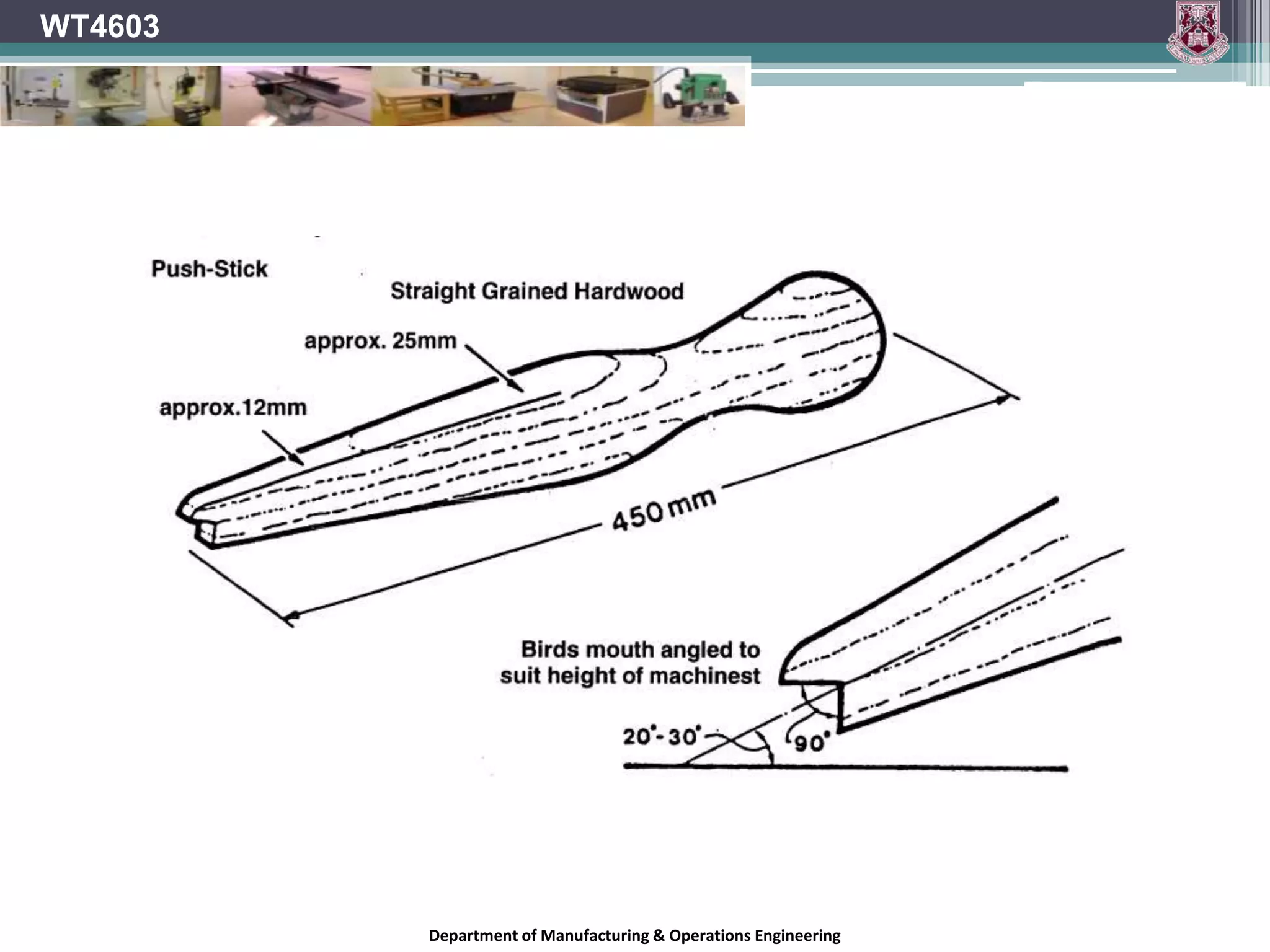
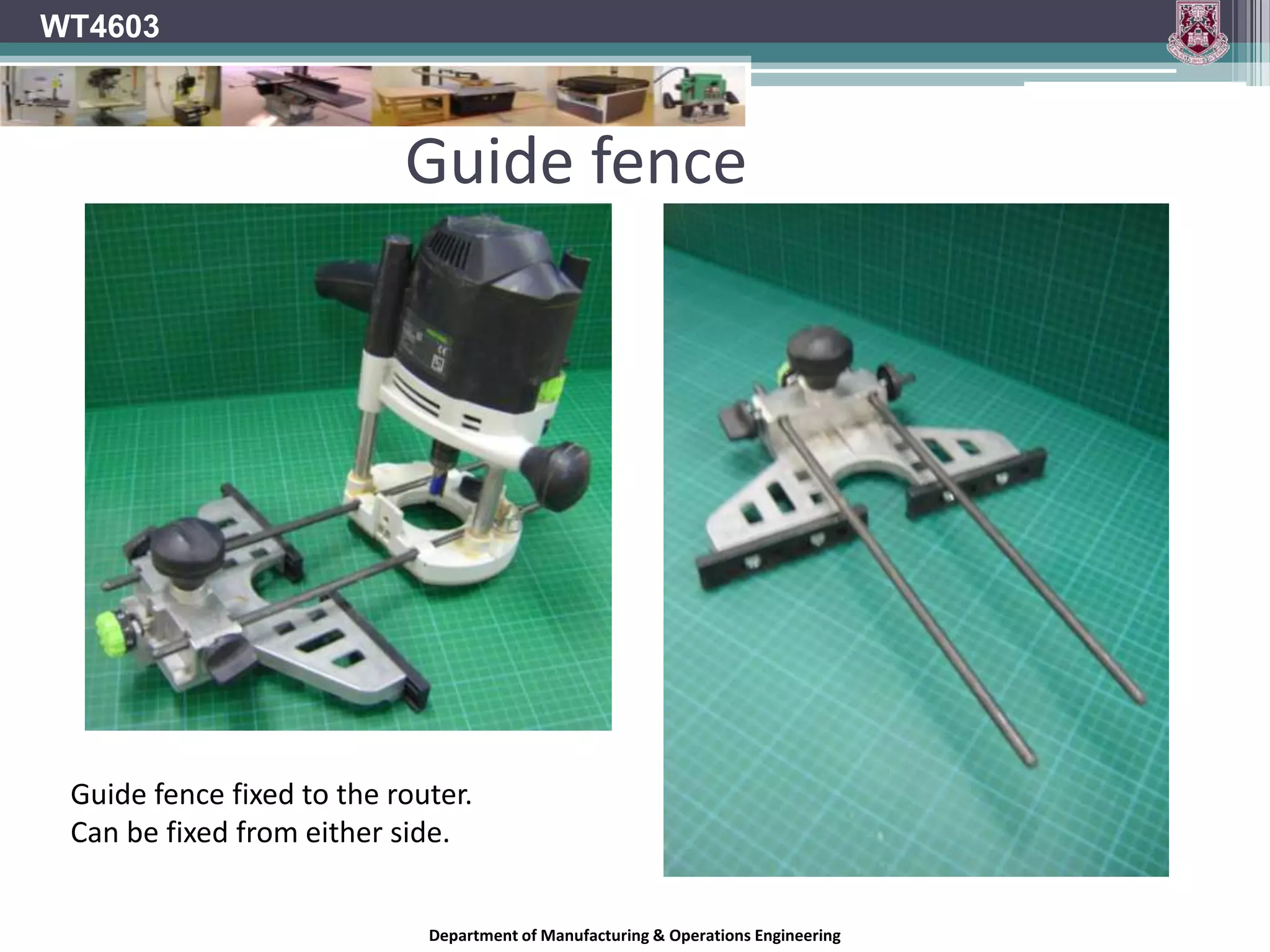
6. WT4603 Hazards Operators should be aware of the following hazards. The work piece can become jammed in the circular sawing machine or can kick back. Hands or fingers can come into contact with the blade. Wood dust can be inhaled. Noise can cause permanent hearing damage. Inadvertent starting of the machine can present a hazard. Department of Manufacturing & Operations Engineering
7. Risk control measures It is essential that the machine be provided with: A means of electrical isolation using a fused switch-disconnector on or adjacent to the machine, and that it is controlled by a starter incorporating overload protection and no-volt release A conveniently positioned, mushroom-headed stop button or suitable other control device that can quickly stop the machine in an emergency WT4603 Department of Manufacturing & Operations Engineering
8. Risk control measures Fixed guards (removable only with the use of a tool), or alternatively interlocked guards that encloses the drive mechanisms. It should be possible to lock the machine to off when not in use, if a locking device is not incorporated in the machine. There should be sufficient space around the saw bench so that the timber can be handled safely. The floor of the work area should be level. The floor surface should be kept free from loose material and should be non-slippery. WT4603 Department of Manufacturing & Operations Engineering
10. WT4603 Hook Angle Department of Manufacturing & Operations Engineering
11. WT4603 Hook Angle On most saw blades, the tooth faces are tipped either toward or away from the direction of rotation of the blade, rather than being perfectly in line with the centre of the blade. Hook angle is the angle formed between the tooth face and a line drawn from the centre of the blade across the tip of the tooth. On a blade with a positive hook angle, the teeth are tipped toward the direction of the blade's rotation. A negative hook angle means that teeth tip away from the direction of rotation, and a zero degree hook angle means that the teeth are in line with the centre of the blade. Department of Manufacturing & Operations Engineering
12. WT4603 Hook Angle Positive Hook Angle Department of Manufacturing & Operations Engineering
13. WT4603 Hook Angle Zero Hook Angle Department of Manufacturing & Operations Engineering
14. Hook Angle WT4603 In both Rip and Cross-cutting saws the Hook angle determines The feel of the cut The quality of the finish The power consumed Department of Manufacturing & Operations Engineering
15. Hook Angle WT4603 The approach angle of the saw varies according to the relative position of the tooth in the downward cutting arc. This angle alters from the top plane of the timber where the tooth top makes first contact to compress the timber before the tooth point engages, to a plane where the tooth angle and the timber face are parallel. Department of Manufacturing & Operations Engineering
16. WT4603 Hook Angle The amount of Hook determines the degree to which the tooth will drive into the timber during the cut. The effect is of the timber being drawn forward. The greater the hook angle the greater this tendency. Too great of a hook angle will result in Harsh cut Tearing Poor finish Less rigid tooth Vibration. Department of Manufacturing & Operations Engineering
17. Hook Angle A blade with high positive hook angle (+20°) will have a very aggressive cut and a fast feed rate. A low or negative hook angle will slow the feed rate and will also inhibit the blade's tendency to "climb" the material being cut. A blade for ripping wood on a table saw will generally have a high hook angle, where an aggressive, fast cut is usually what you want. Radial arms saws and sliding compound mitre saws, on the other hand, require a blade with a very low or negative hook angle, to inhibit overly fast feed rate, binding, and the blade's tendency to try to "climb" the material WT4603 Department of Manufacturing & Operations Engineering
18. Tooth Configuration The shape of the saw blade tooth and the way the teeth are grouped also affect the way the blade cuts. The configuration of the teeth on a saw blade has a lot to do with whether the blade will work best for ripping, crosscutting, or laminates. Of course, no matter which tooth design you're looking at, more teeth will give you a smoother cut than fewer teeth. WT4603 Department of Manufacturing & Operations Engineering
19. WT4603 Tooth Configuration A ripping blade will have a Flat Top Grind (FTG) for fast cutting with the grain. Department of Manufacturing & Operations Engineering
20. WT4603 Tooth Configuration A cross cut blade will do the best job with an Alternating Top Bevel (ATB), cutting across the grain like a knife and producing a very smooth cut. Department of Manufacturing & Operations Engineering
21. WT4603 Tooth Configuration A blade with Triple Chip Grind (TCG) is good for all-purpose cutting and also gives you a very clean cut. TCG blades are also good for cutting non-ferrous metals and plastics. Department of Manufacturing & Operations Engineering
23. Tooth Configuration In general, blades with more teeth yield a smoother cut, and blades with fewer teeth move material faster. A 250mm blade designed for ripping wood can have as few as 24 teeth, and is designed to quickly move material along the length of the grain. A rip blade isn't designed to yield a mirror-smooth cut, but a good rip blade will move through wood with little effort and leave a clean cut with a minimum of scoring. WT4603 Department of Manufacturing & Operations Engineering
24. Tooth Configuration WT4603 A crosscut blade is designed to give a smooth cut across the grain of the wood, without any splintering or tearing of the material. A crosscut blade will usually have from 60 to 80 teeth. More teeth mean that each tooth has to cut less material. The result is a cleaner cut on edges and a smoother cut surface. With a top-quality crosscut blade, the cut surface will appear polished. Department of Manufacturing & Operations Engineering
25. WT4603 Gullet The gullet is the space cut away from the blade plate in front of each tooth to allow for chip removal. In a ripping operation, the feed rate is faster than in crosscutting and the chip size is bigger, so the gullet needs to be deep enough to make room for the large amount of material it has to handle. In a crosscutting blade the chips are smaller and fewer per tooth, so the gullet is much smaller. The gullets on some crosscutting blades are purposely sized small to inhibit a too-fast feed rate, which can be a problem, especially on radial arm and sliding mitre saws. Department of Manufacturing & Operations Engineering
26. Gullet WT4603 The gullets of a combination blade are designed to handle both ripping and crosscutting. The large gullets between the groups of teeth help clear out the larger amounts of material generated in ripping. The smaller gullets between the grouped teeth inhibit a too-fast feed rate in crosscutting Department of Manufacturing & Operations Engineering
27. Riving Knife WT4603 The riving knife must be tapered at its leading edge Note : The thickness of the riving knife is to be approx. 10% thicker than the plate of the saw blade but must be less than the saw kerf “B”. Department of Manufacturing & Operations Engineering
28. WT4603 Riving Knife Riving knife should not be set higher than the highest point of the saw blade Department of Manufacturing & Operations Engineering
29. WT4603 Riving Knife Max and min distances between saw blade and riving knife. Distances are measured in a radial direction Department of Manufacturing & Operations Engineering
30. WT4603 Riving Knife Max and min distances between saw blade and riving knife. Distances are measured in a radial direction Department of Manufacturing & Operations Engineering
31. WT4603 Riving Knife Shaded area can be included in the riving knife profile Example 2 reduces the Ø of blade that can be fitted to the machine and has a weak point Department of Manufacturing & Operations Engineering
32. WT4603 Riving Knife When viewed in the direction of the blade edge the riving knife should not be visible to the operator. Department of Manufacturing & Operations Engineering
33. WT4603 Table Slot Table slot width max. and min. measurements for saw blade ranges. Min. and max. measurements for distance from blade face to edge of table slot. Department of Manufacturing & Operations Engineering
34. WT4603 Table Slot Max. distance between saw blade and front edge of table slot. (Blade raised to highest level) Department of Manufacturing & Operations Engineering
35. WT4603 Table Slot Max. distance between saw blade and front edge of table slot on machine with a scoring blade. (Blade raised to highest level) Department of Manufacturing & Operations Engineering
36. Clearance WT4603 The supporting body of the cutting tip is ‘relieved’ or ground back (X) so that only the cutting edge itself makes work contact. For any machine cutting tool to work efficiently, only the cutting edge of the tool should be making contact with the work. Department of Manufacturing & Operations Engineering
37. Clearance Work clearance must be provided. The saw tooth provides this clearance. The ‘Kerf’ produced by the teeth must be wider than the supporting saw plate. Steel saws had the kerf formed by bending or ‘setting’ alternate teeth laterally. With tipped saws the tips are wider than the saw plate and thus create the clearance. Clearance or relief bevels are ground on the sides and the top of each tooth. WT4603 Department of Manufacturing & Operations Engineering
38. Plate Tension A flat disc will remain flat and true if turned at a slow speed. When variable stresses are created on this disc due to: Braking effect of sawing Heating effect of friction Outward pull of centrifugal force the outer rim area of the disc will expand. If the whole area of the disc can expand at the same rate the disc will remain flat and true. This does not happen with a saw blade. The central region of the blade is clamped between the collars and does not expand. WT4603 Department of Manufacturing & Operations Engineering
39. Plate Tension Only the teeth of the saw blade should make contact with the work and a portion of the energy expended in cutting will unavoidably be converted to heat. The periphery of the blade will therefore tend to warm up more quickly than the main plate body. This will cause the periphery of the blade to expand. If this is not taken into account the blade will distort. To prevent this saw blades are ‘tensioned’ during the manufacturing stage. Rim speed will determine the amount of tension required in a particular saw blade. Thinner saw blades require greater tension. Faster saws require more tension. WT4603 Department of Manufacturing & Operations Engineering
40. Plate Tension Traditionally this was done by highly skilled labour but modern saw manufacturers use machine operated rollers to achieve a faster more uniform result. This within limits allows the plate to expand uniformly in uneven temperature gradients. A blade which has lost its tension will be seen to be throwing from side to side. This is most noticeable as the blade slows down after the machine is switched off. If this is the case the blade should be removed and sent for servicing. This can be reduced by cooling the blade tip while in operation by packing. WT4603 Department of Manufacturing & Operations Engineering
41. Plate Tension TC tipped blades have an extremely long life and to assist the tension factor, slots are incorporated around the edge of the blade. These allow a degree of individual expansion between segments on the plate edge. They also break up harmonic frequencies, which build up during the sawing process. WT4603 Department of Manufacturing & Operations Engineering
42. Top Guard Covers the top edge of the saw blade. Deflects waste. Prevents accidental contact with the uppermost teeth of the blade. It can also limit the effects of material rejection. WT4603 Department of Manufacturing & Operations Engineering
43. WT4603 Top Guard Department of Manufacturing & Operations Engineering
44. WT4603 Blade Guard Blade guard that completely encloses the blade Department of Manufacturing & Operations Engineering
45. WT4603 Blade Guard Guard not connected to riving knife Guard has lead in at the front Dust extraction integrated in the guard Department of Manufacturing & Operations Engineering
49. WT4603 Circular Sawing Machines Scoring blade rotates in the opposite direction to the saw blade Scoring blade cuts on the up stroke of the cut to ensure a clean cut is produced on the underside of the panel Department of Manufacturing & Operations Engineering
50. WT4603 Circular Sawing Machines Work being fed into the blade Blade rotates clockwise (Guarding not shown) Department of Manufacturing & Operations Engineering
51. Circular Sawing Machines WT4603 Top surface – fibres being compressed Bottom surface – fibres being ripped out Will damage the under side of the material Department of Manufacturing & Operations Engineering
52. WT4603 Circular Sawing Machines Top cutting “into the wood” Bottom “cutting out of the wood” Department of Manufacturing & Operations Engineering
53. WT4603 Circular Sawing Machines Scoring blade introduced Will make an initial shallow cut before the larger saw blade will cut the material Department of Manufacturing & Operations Engineering
54. WT4603 Circular Sawing Machines In this diagram the scoring blade rotates in the same direction as the saw blade Is this blade still cutting “out of the wood” on the underside ? Department of Manufacturing & Operations Engineering
55. WT4603 Circular Sawing Machines Here the scoring blade revolves in an anti clockwise direction. As the material passes this blade the cut produced is “into the wood” Department of Manufacturing & Operations Engineering
56.
57. Should only be used when crosscutting or ripping sheet material where a clean finished cut is required on both surfaces of the panelDepartment of Manufacturing & Operations Engineering
58. Calculations WT4603 Saw Calculations Rim Speed (P) = x x Spindle Speed (R) Where P = Rim Speed R = Spindle Speed = Diameter in metres Units = m x 1/min = m/min This speed is expressed in metres per minute m/min It is left in this format because spindle speed is expressed in Rev/min Department of Manufacturing & Operations Engineering
59. Calculations Problem 1 A saw blade of 750mm is required to run at a rim speed of 3048m/min Calculate the number of revs per min that will achieve this speed. P = x x R P 3048 R = ---------- = ----------------- = 1294.3 RPM x 3.142 x .750 WT4603 Department of Manufacturing & Operations Engineering
60. Calculations WT4603 Problem 2 A circular saw has a motor that revolves at 1500 Rev/min The of the blade is 720mm. Calculate the rim speed for the blade. Department of Manufacturing & Operations Engineering
61. WT4603 Saw Parts Guard Fence Blade Riving Knife In feed table Out feed table Start / Stop Foot stop Department of Manufacturing & Operations Engineering
66. WT4603 Fence Must be parallel to the saw blade Clamping mechanism cam screw lock Sliding fence Horizontal position Vertical position Department of Manufacturing & Operations Engineering
74. When the piece is moved by operator or vibration it will contact the moving blade and get ejected
75. This will result in possible injury to the operator, damage to the blade and damage to the materialDepartment of Manufacturing & Operations Engineering
93. WT4603 Hand Router Cutting grooves Cutting rebates Cutting slots and recesses Cutting beads or mouldings Cutting dovetails Cutting dovetailed slots and grooves Edge trimming Profiling (jigs/formers) Department of Manufacturing & Operations Engineering
94. WT4603 Hand Router: Power Large powerful routers are heavy and can be difficult to handle for light work. Generally in schools the type of work that the router will have to perform will be light to medium work. As a rough guide to classifying routers: 400 W to 600W are for light duty 750 W to 1200W are for medium duty 1250 W upwards are for heavy duty Department of Manufacturing & Operations Engineering
95. WT4603 Speed Machine speed can range from about 800 to 30000 rpm. Nearly all modern routers have variable speed motors, the setting is by a simple numbered knob showing up to 5 or 6 positions. The required speed will depend upon the size of cutter being used and the material being cut. The appropriate speed setting for any combination will need to be determined by trial and error/experience. The variable speed control should not be in a position where it could inadvertently be changed while routing. Department of Manufacturing & Operations Engineering
96. Hand Router WT4603 Router cutter (bit) is fitted to a collet on the lower end of the motor It is a direct drive system Motor sizes can vary from ½ horse power to 3½ horse power The bigger the motor the heavier the router Cutter profile will often determine the size of the motor required for the job Department of Manufacturing & Operations Engineering
97. WT4603 Hand Router Collet Simple but accurate chuck Attached directly to the bottom of the motor armature Collet holds the bit so that the motor can make it spin Two most common size collet are 6mm and 12mm 12mm collet will hold a bit with a 12mm shank which is stronger than the 6mm Department of Manufacturing & Operations Engineering
98. Hand Router WT4603 The base of the router is what holds the motor in position in relation to the work It usually incorporates two operating handles Handles used to control the machine Can be used to lock/release depth plunge Can contain on off switch Base plate of the router is a plastic sole on the bottom of the base Reduces frictional contact with material Department of Manufacturing & Operations Engineering
99. WT4603 Hand Router Motors rated on their horse power Will also have an amperage rating Determines the maximum amount of current the motor can draw in continuous use without overheating and burning out Routers may have the same horsepower rating and different amperage rating e.g. 1 ½ hp drawing 8 amps 1 ½ hp drawing 10 amps Department of Manufacturing & Operations Engineering
100. Hand Router WT4603 Router motor is of the universal brush type which is primarily used for intermittent, variable speed operations Induction motors (brushless) are primarily used for long term fixed speed operations such as the circular saw etc. This is the reason why a 1 ½ hp router motor is much smaller than a 1 ½ hp circular saw motor Department of Manufacturing & Operations Engineering
101. Cutter Speed The router is a high speed cutting machine Generally it is taken that the higher the speed the smoother the cut However if the cutter diameter is increased the peripheral cutter speed increases which can make the machine hard to control and prone to damaging the material Can also lead to burning of the wood and blunting of the cutting edge WT4603 Department of Manufacturing & Operations Engineering
102. Collet Like a drill chuck it is designed to hold a round shank bit The collet makes almost full contact with the cutter shank unlike the three fingered shank of the drill chuck Router bit shanks must be sized to match the inside diameter of the collet Collet must hold cutter while revolving at high speed Must also be able to resist side loading WT4603 Department of Manufacturing & Operations Engineering
103.
104. If you push the router into the material from position (A), the router will pull to your left.
105. If you pull the router into the material toward you from position (B), the router will pull to your right.
106. This occurs as the cutter will climb on the material in front of the cutting edge.
107. This motion must be utilised when using guide fences.Department of Manufacturing & Operations Engineering
108. WT4603 Feed direction & the fence To process a straight housing or trench you can use a straight edge guide (A) or the guide fence that is supplied with the router(B). Department of Manufacturing & Operations Engineering
111. The router will try to pull to the operators left hand side.
112. With the fence clamped on the left of the router, the router will push against it as it is fed into the material.(Green arrows)
113. If the fence were on the right hand side (when viewed from the operators position) of the router, it would pull away from the fence and result in the trench being crocked.Department of Manufacturing & Operations Engineering
119. Feeding the router in the opposite direction will cause any dust to be blown away from the operator.
120. This will require the guide fence to be set up on the right hand side of the router and operator. F Feed direction & the fence Department of Manufacturing & Operations Engineering
121. WT4603 Guide fence Guide fence fixed to the router. Can be fixed from either side. Department of Manufacturing & Operations Engineering
122. WT4603 F P Using the guide fence When feeding the router forward (F) the router will tend to pull to the operators left hand side. The fence should be set on the right hand side of the router. When the cutter engages in the material it will pull to the left as indicated by the green arrow (P) and keep the fence tight against the materials edge. Material should be securely calmped or placed on a non-slip router mat. Department of Manufacturing & Operations Engineering
123. WT4603 Profiles can be processed on material using templates. Templates can have the required profile as an internal shape or an external profile. To process the section marked (A) In the photo an internal template can be used to guide the router to produce the profile. Feed direction can be established using the right hand rule. Department of Manufacturing & Operations Engineering
125. WT4603 Using the template guide Fit the template guide to the router base plate. Set cutter plunge depth. Place over template at the starting position (A). Switch on the router and then plunge to depth (B). Feed router in a clockwise direction. Department of Manufacturing & Operations Engineering
126. WT4603 ROUTER PULLS TO THE LEFT FENCE PULLED TOWARDS WORKPIECE FEED DIRECTION Router Station 1 Carry out the following operations: Isolate the router. Select V- groove cutting bit. Fit the bit in the router securely. Set the depth of the cut to 3mm. Machine the profile shown on the drawing using the guide fence. (Note: Guide fence is set. Do not adjust.) Isolate the router. Remove the cutter from the router. Department of Manufacturing & Operations Engineering
127. WT4603 Router Station 3 Carry out the following operations: Isolate the router. Select Ø 6mm cutting bit. Fit the bit in the router securely. Set the depth of the cut to 5mm. Set the depth turret to machine to a depth of 10mm on the second pass. Fit the guide fence to the router. Set the guide fence to the dimension shown on the drawing. Machine the profile shown on the drawing using the guide fence. Isolate the router. Remove the guide fence and Ø 6mm cutting bit from the router. Department of Manufacturing & Operations Engineering
128. WT4603 Router Station 4 Carry out the following operations: Isolate the router. Select Ø 12mm cutting bit cutting bit. Fit the bit in the router securely. Fix the template guide to the base of the router. Set material in the template. Set the depth of the cut to 5mm. Set the depth turret to machine to a depth of 10mm on the second pass. Machine the profiles of the template using the template guide. Isolate the router. Remove the template guide and Ø 12mm cutting bit from the router. Department of Manufacturing & Operations Engineering
129. WT4603 Designing An Effective Poster Department of Manufacturing & Operations Engineering
130.
131. Posters vary in size depending on the purpose and space where it must be displayed
141. The use of safety signs, as visible in lab, is also encouraged but must be hand drawn and rendered.Department of Manufacturing & Operations Engineering
142.
143. Poster text should be produced electronically, unless it can be presented clearly through other means.
144. Hand written text is often ineffective unless technical print text is performed with care, which is also acceptable.
145. The positioning of text is crucial in this poster assignment as you want to make it relevant to machine parts, operational use and health and safety.
146. You may also apply the use of a key legend as a means to linking poster features with user information/activity sheets. Department of Manufacturing & Operations Engineering
152. The specific use of colours should be evident in the design of your safety postersDepartment of Manufacturing & Operations Engineering
153.
154. In the case of this poster assignment it is suggested that blue is used appropriately, but not for the entire background…as this will waste ink and prove costly in terms of printing.
155. It is suggested that a clear-white background be used with text information being presented in different colours, in particular instructional information (blue)Department of Manufacturing & Operations Engineering
156.
157. People tend naturally to view poster items in a clockwise manner unless there is a clear distinction of items on a given poster i.e. number sequence, separation of text and images/graphics, headings, sub-headings etc…
158. This poster is pre-dominantly for classroom use for ages ranging from 13-18yrs of age, therefore a safety posters for any machine should be arrange in a simple and easy to follow mannerDepartment of Manufacturing & Operations Engineering