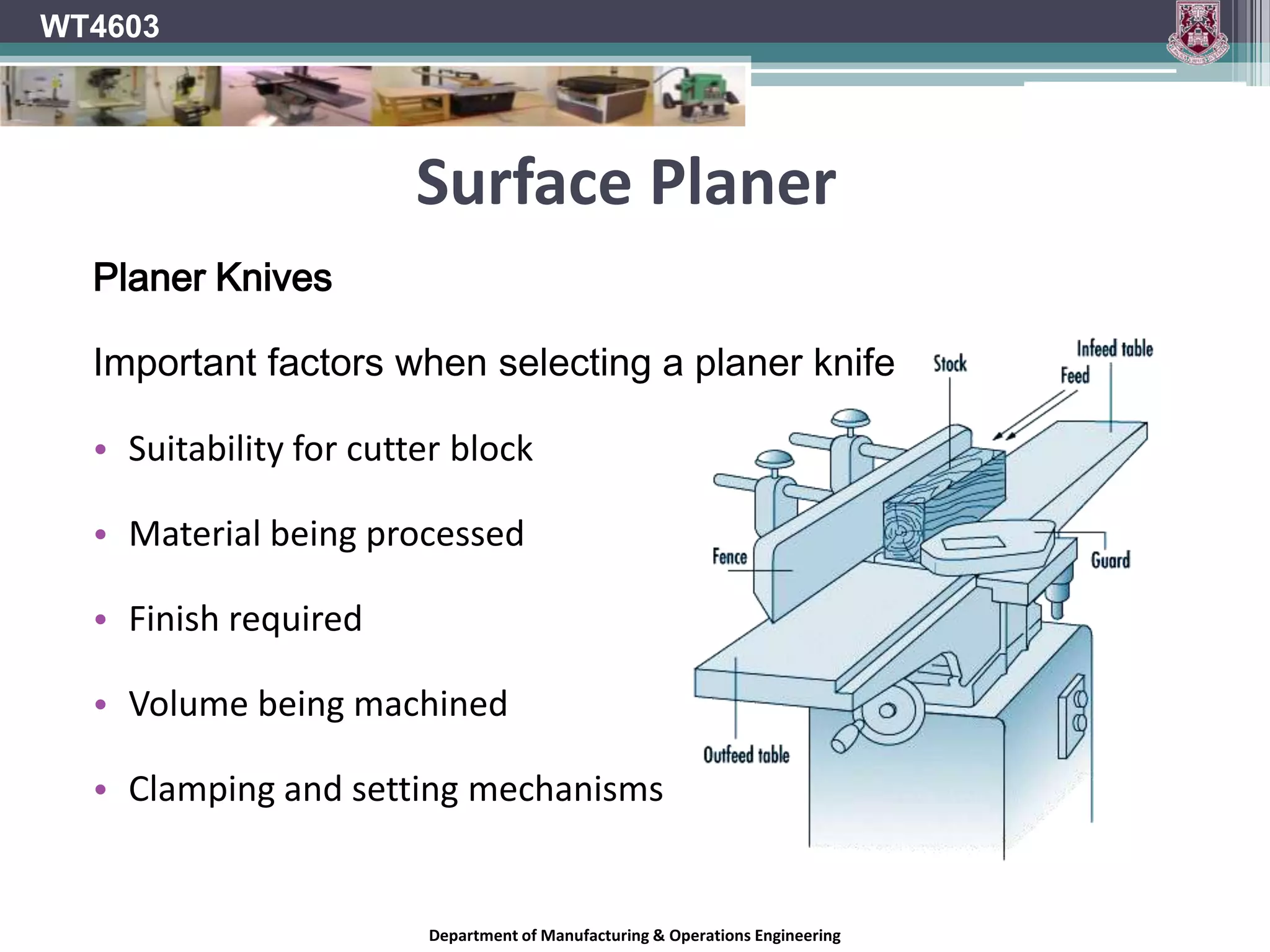
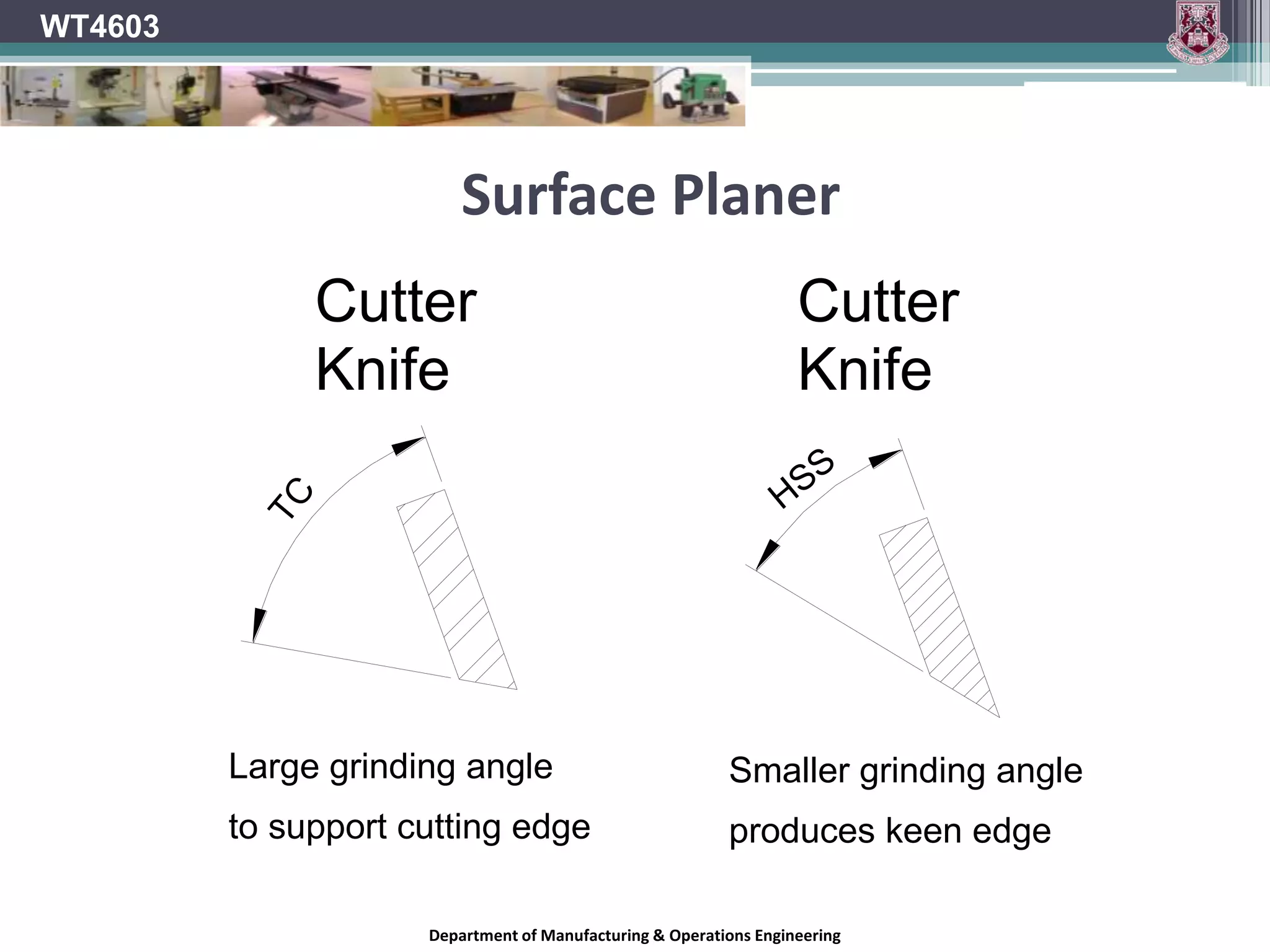
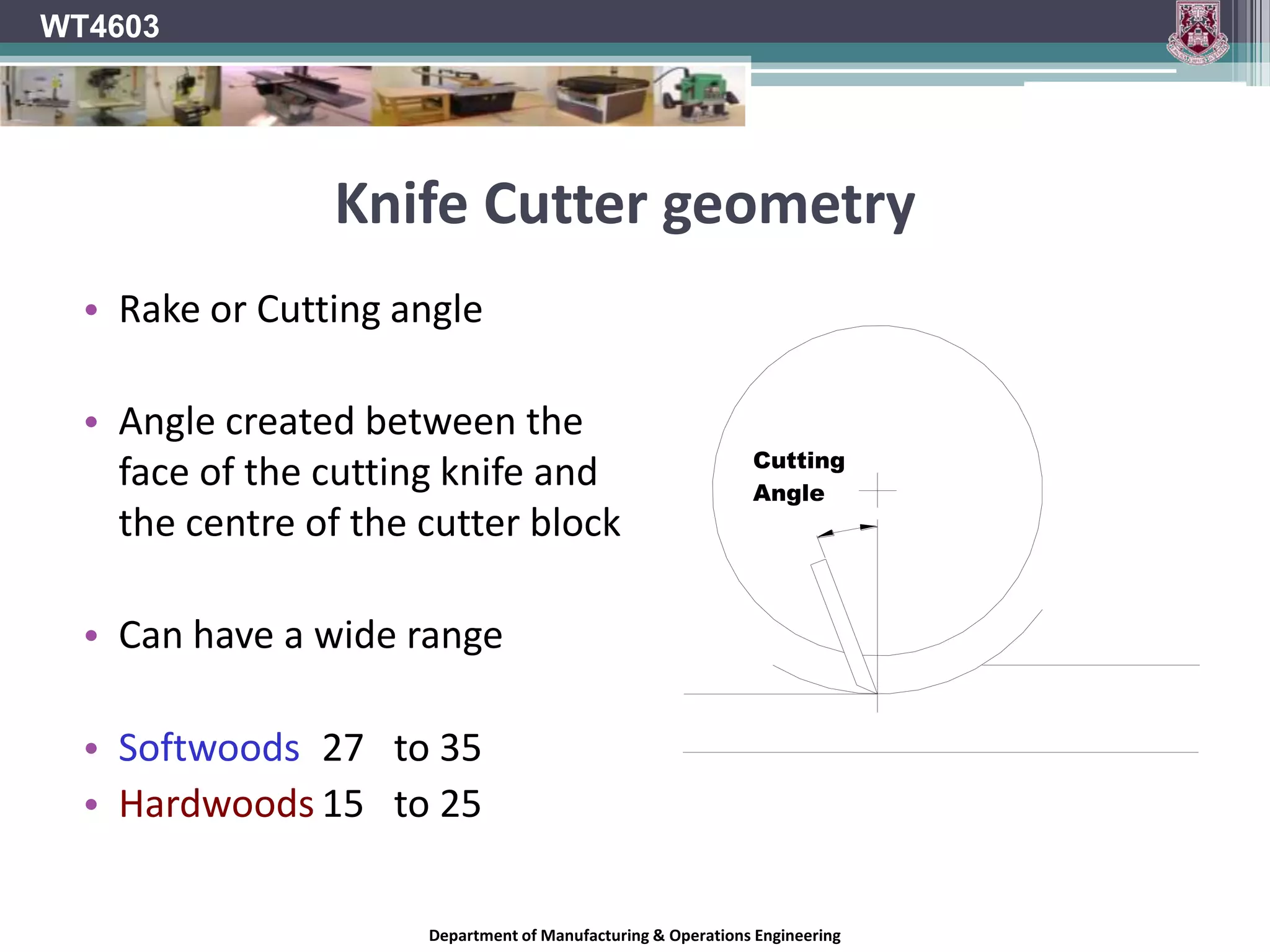
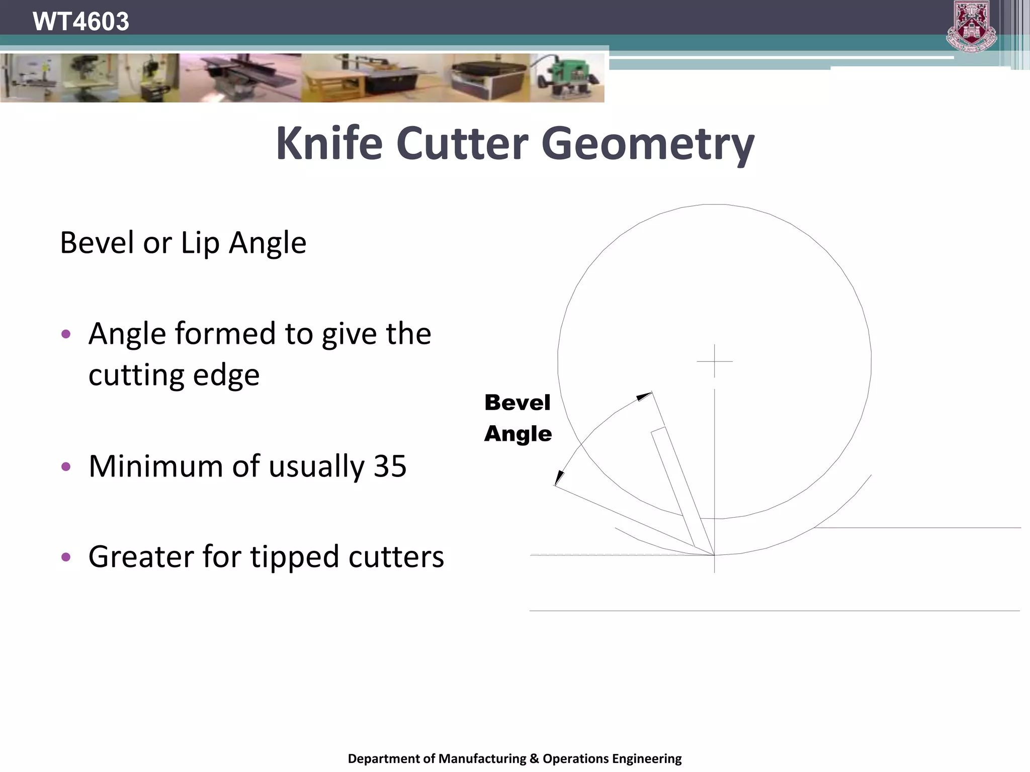
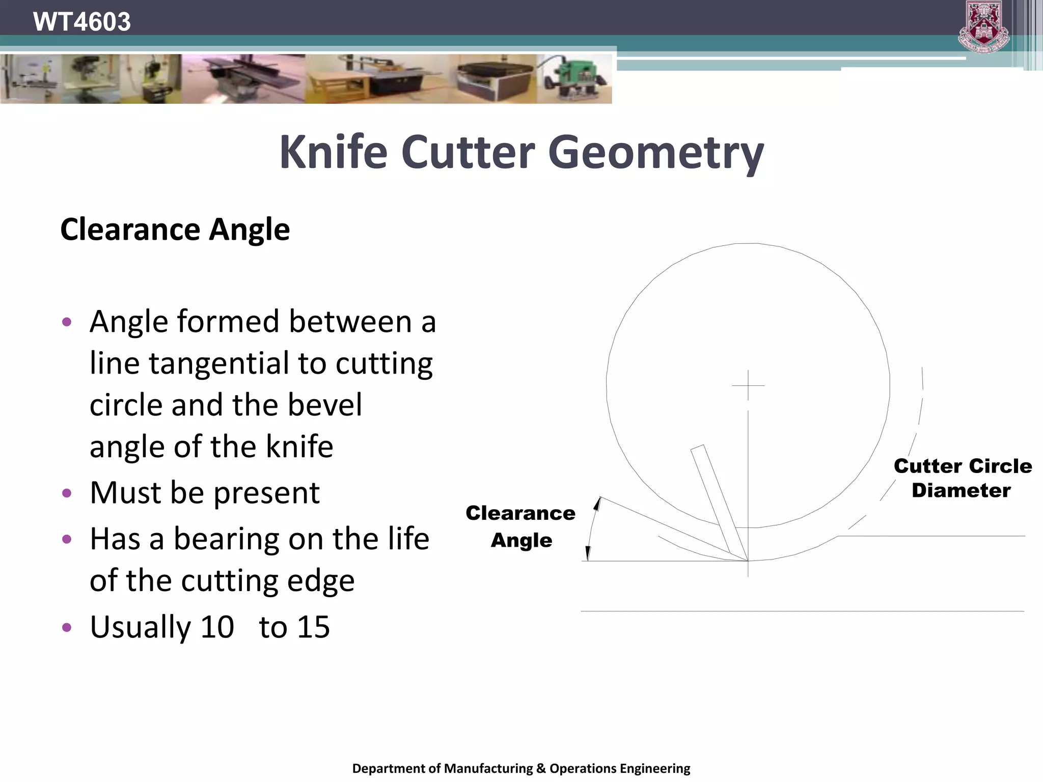
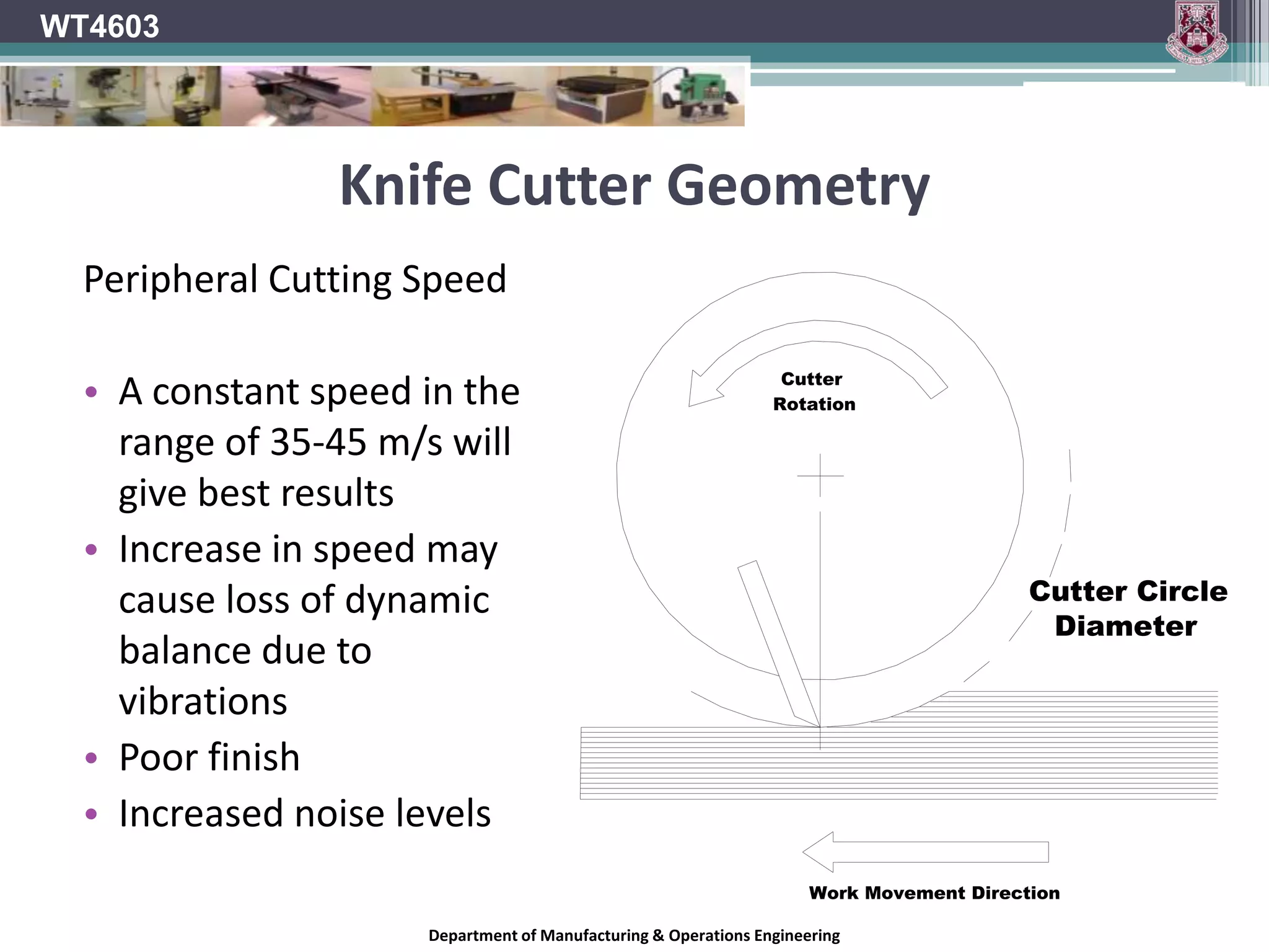
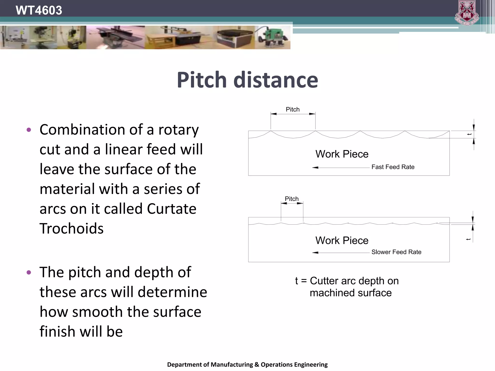
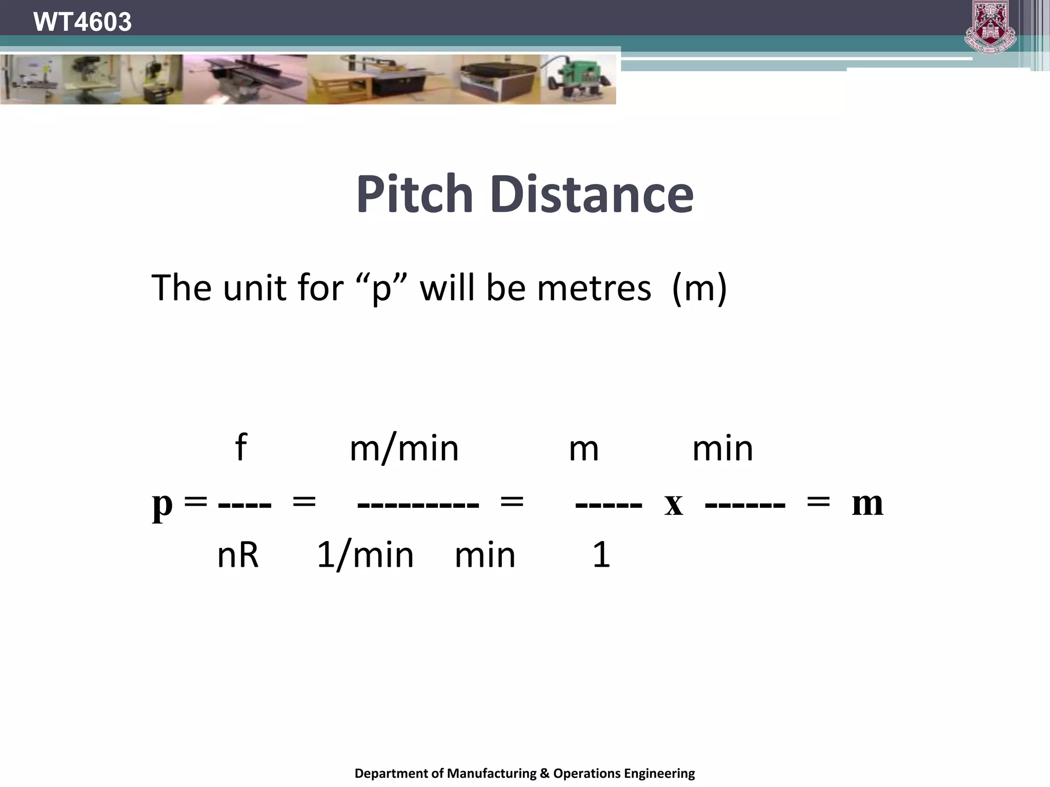
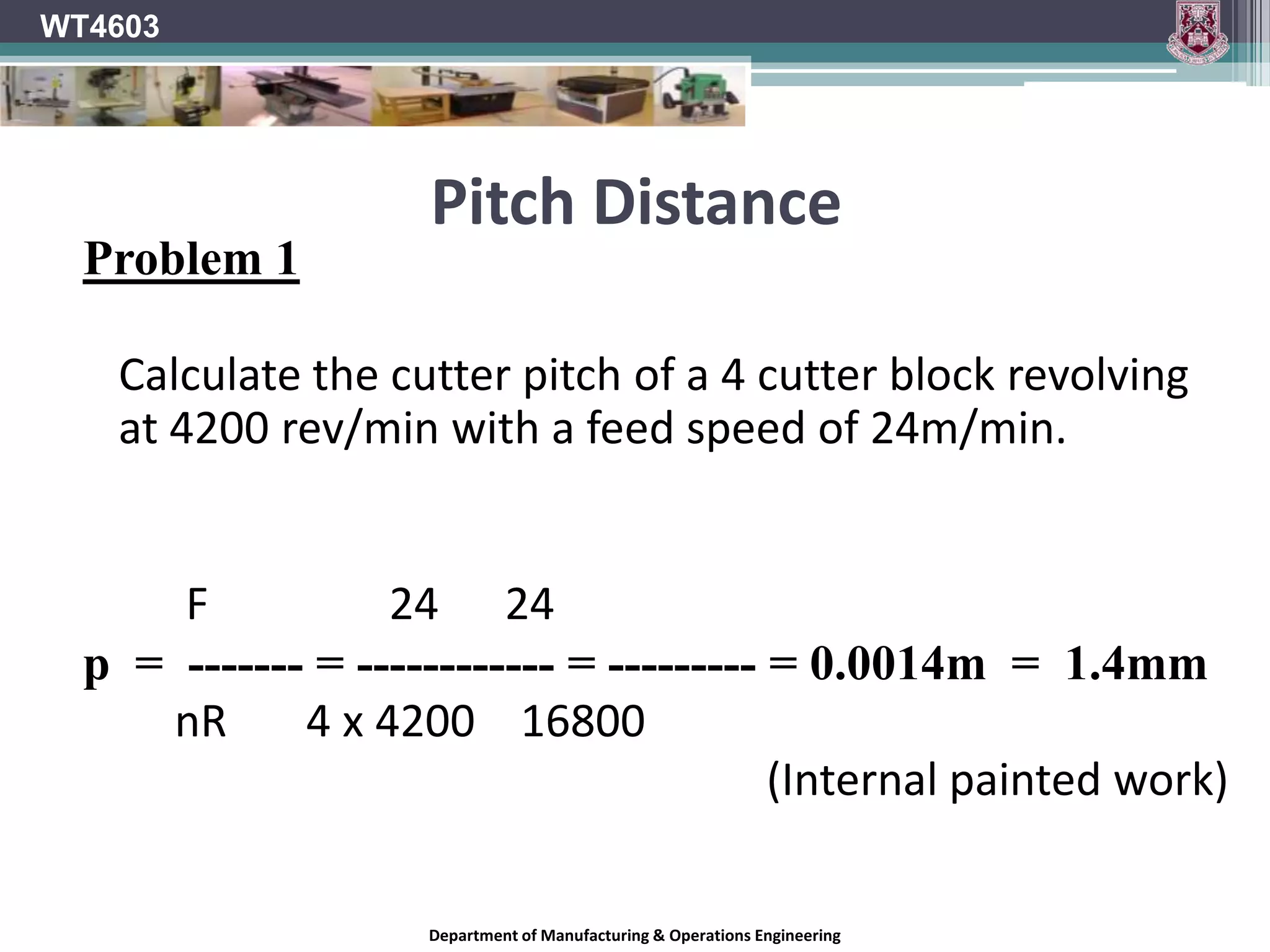
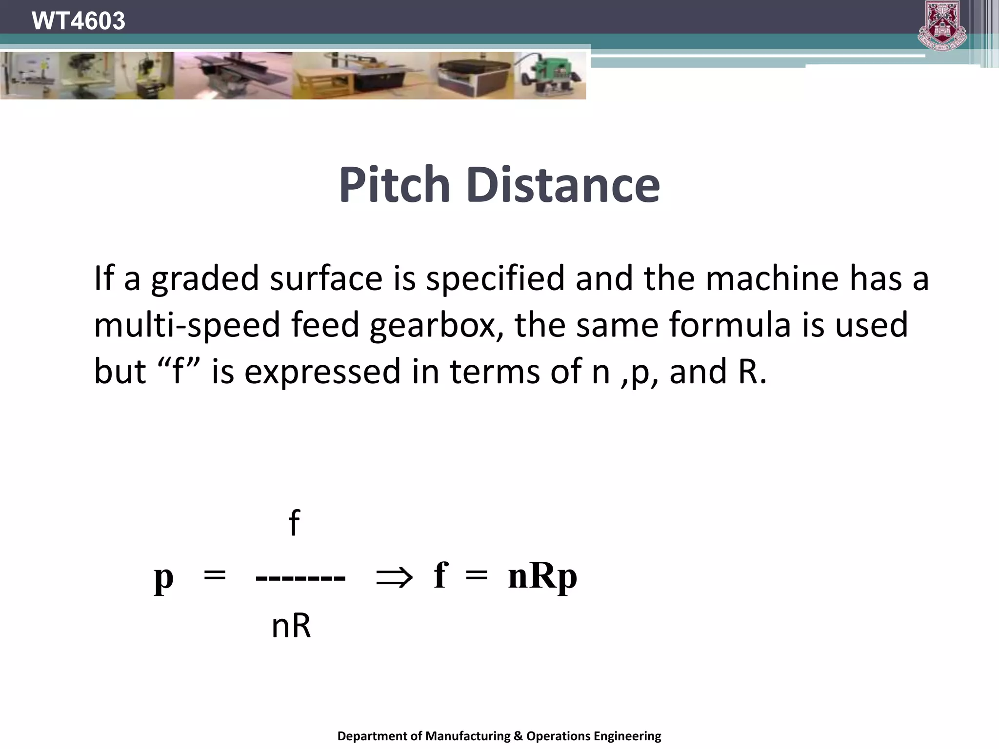
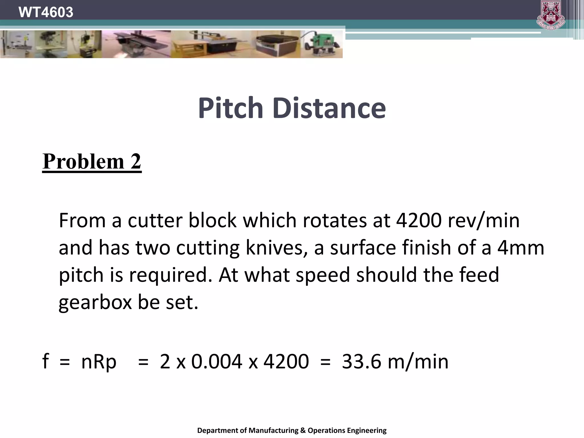
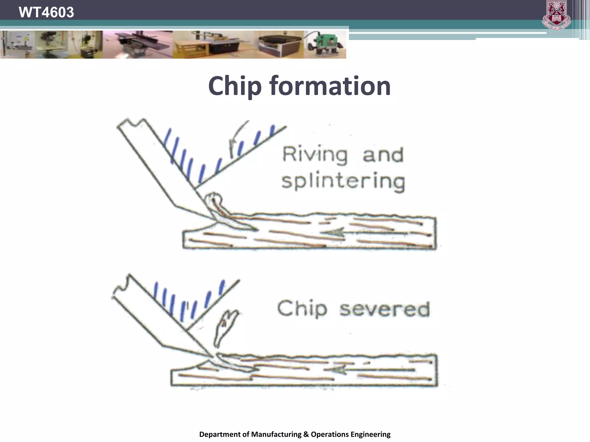
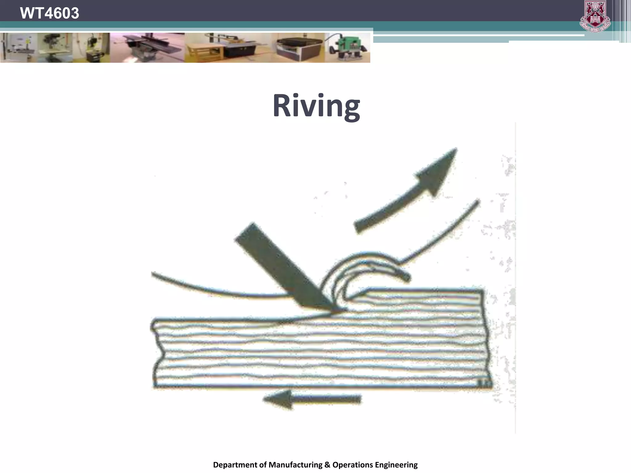
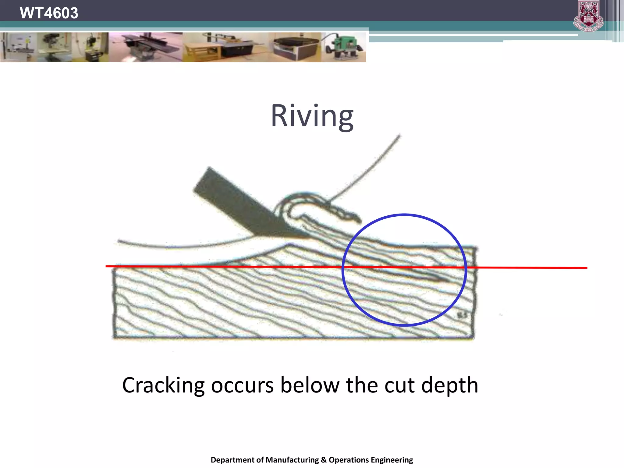
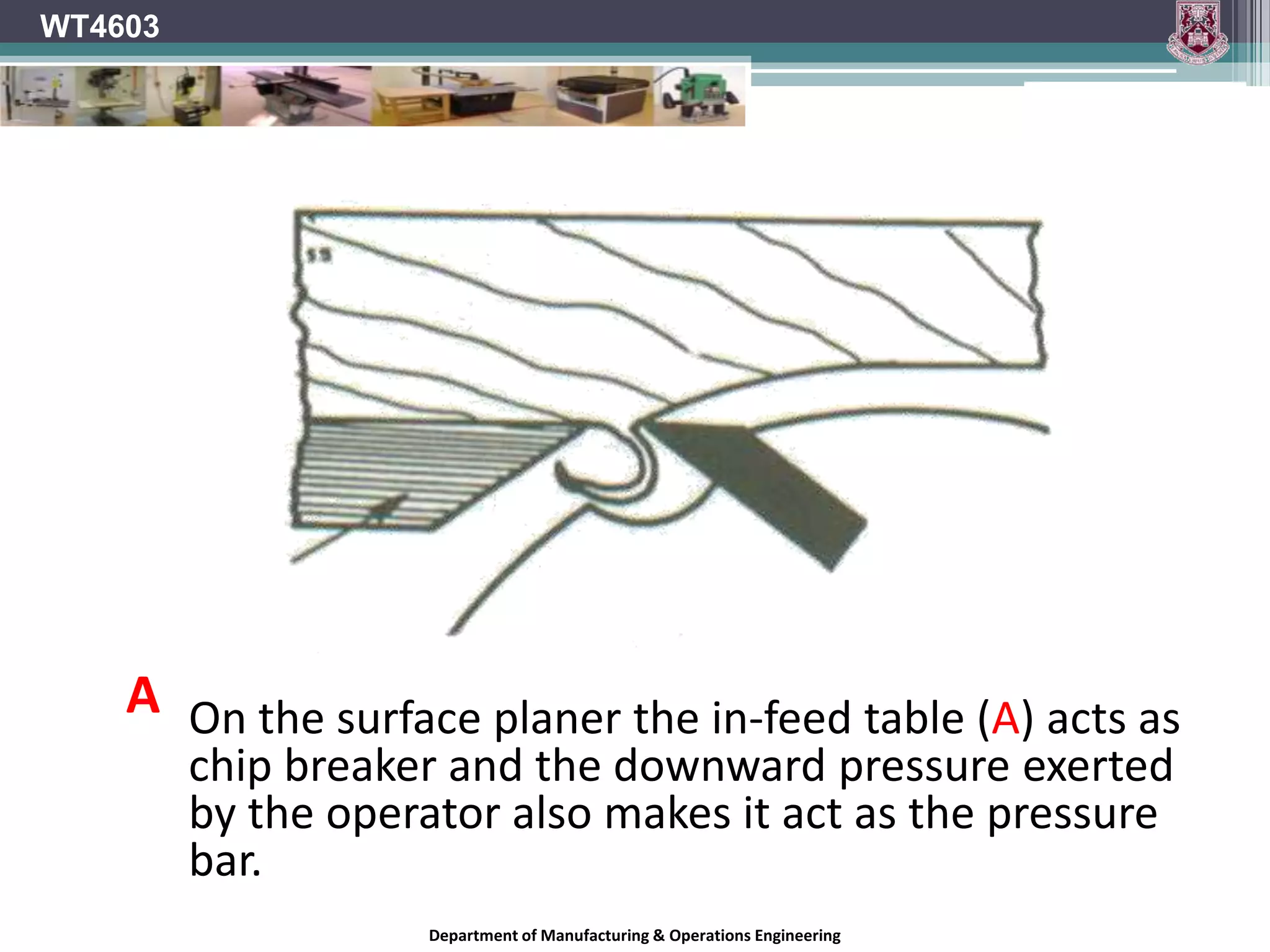
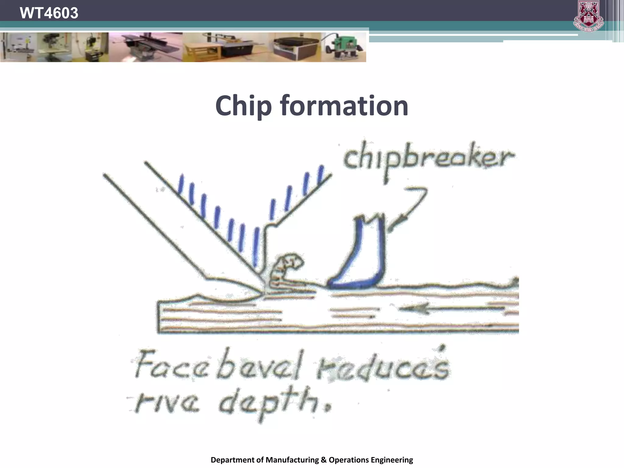
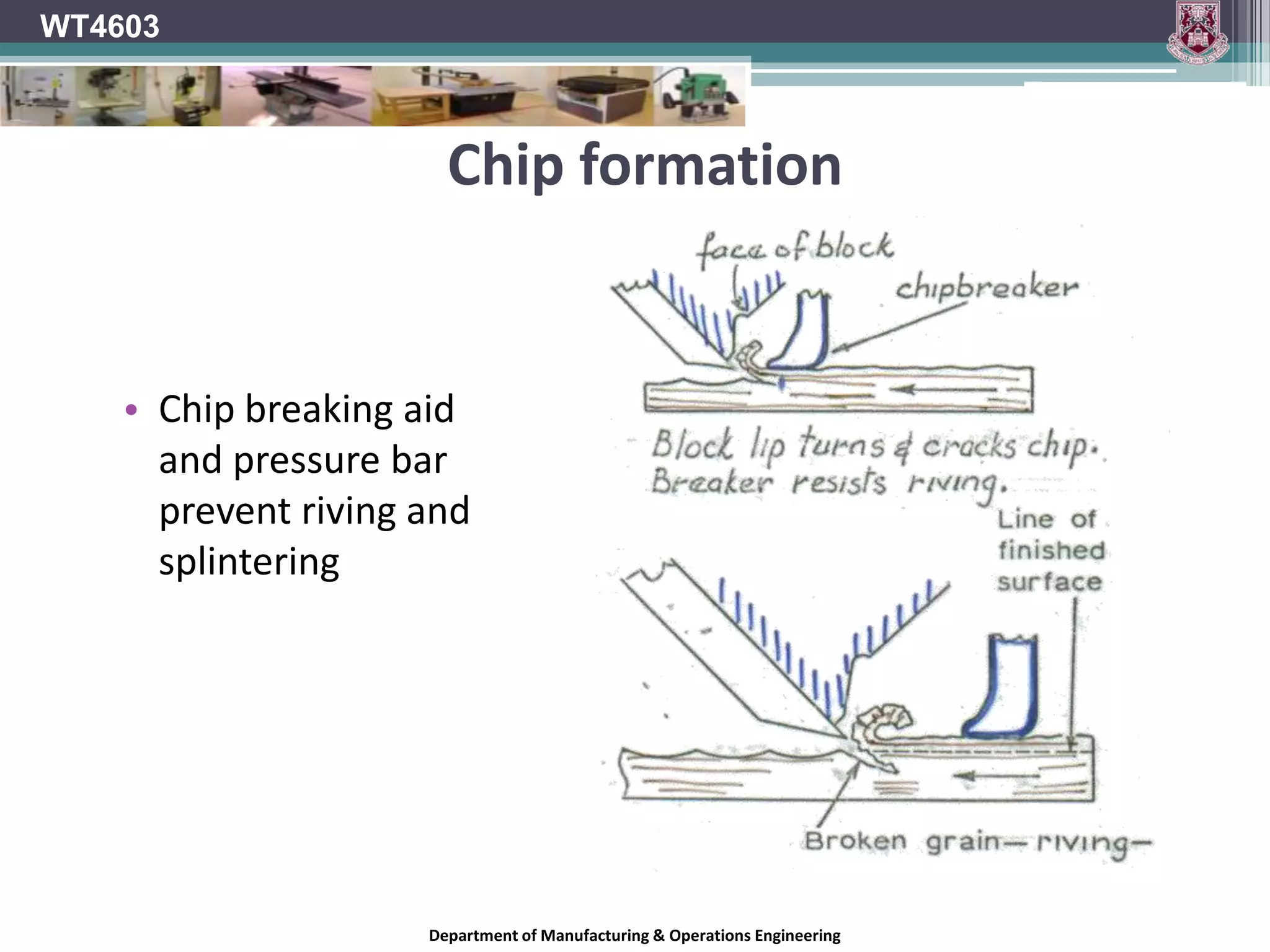
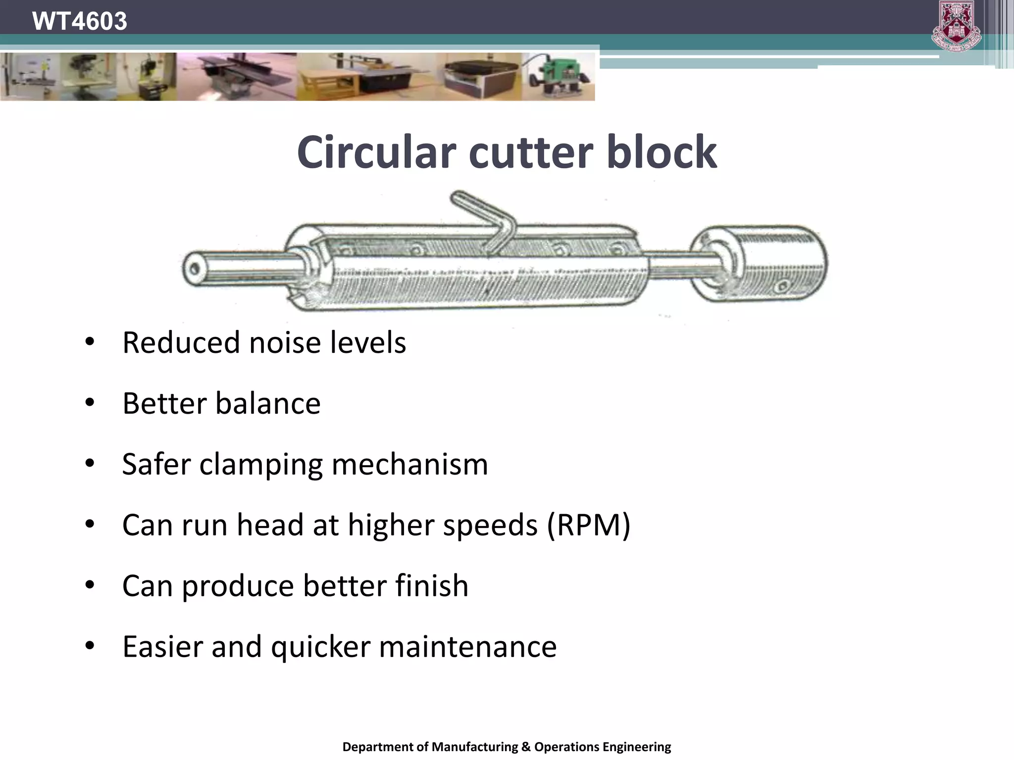
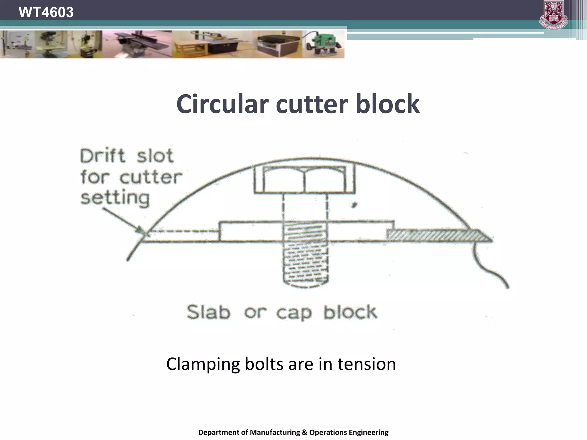
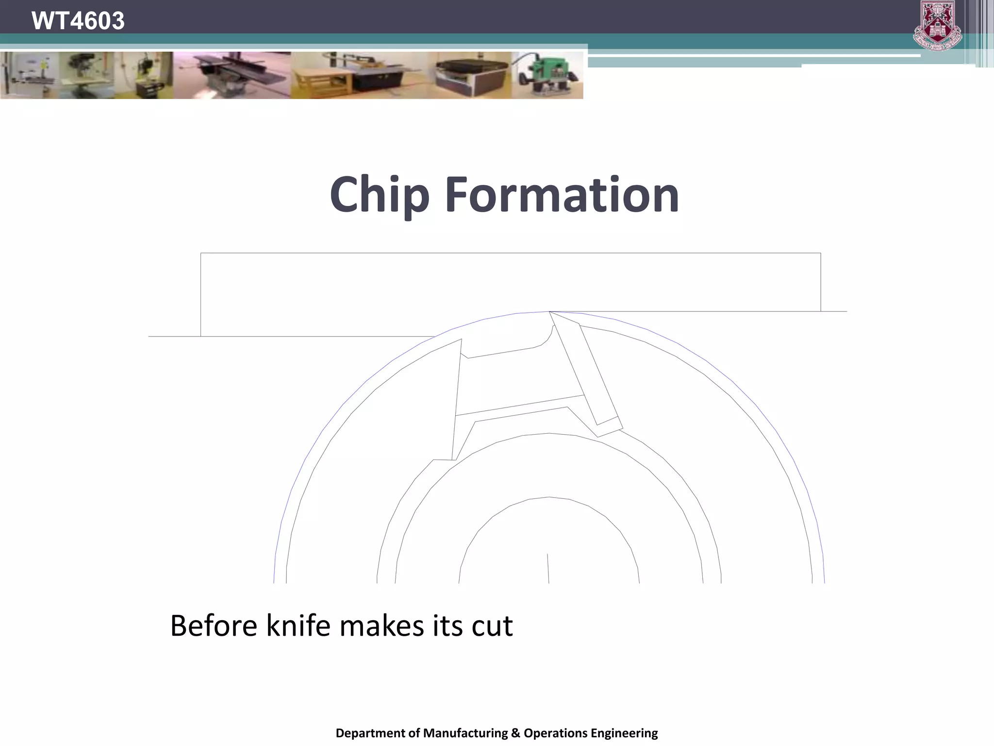
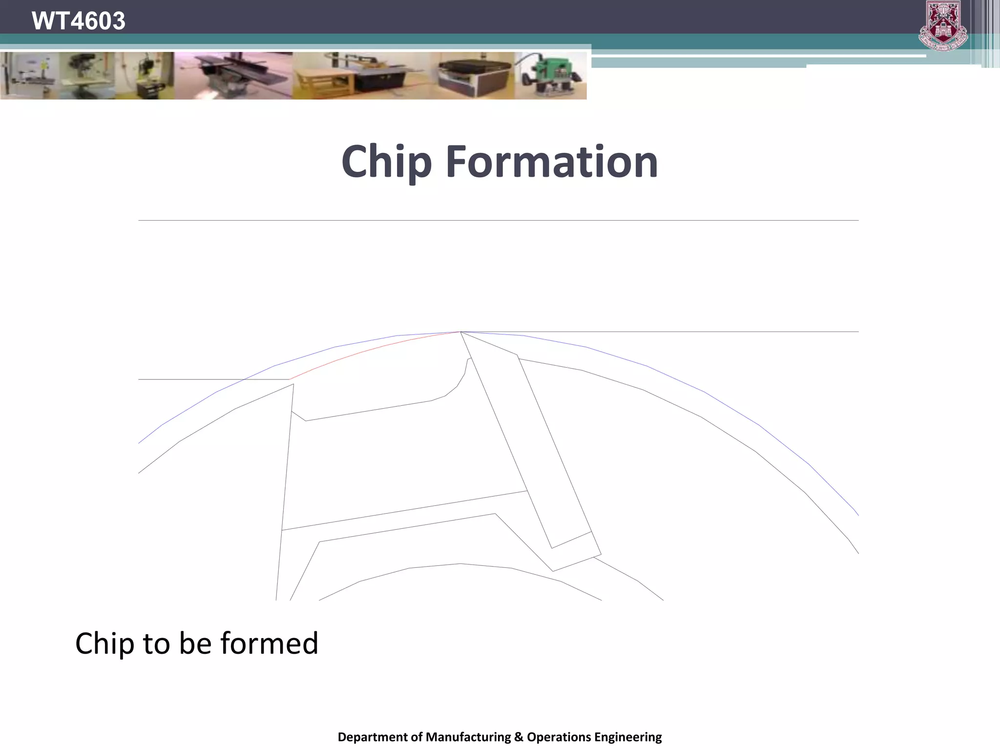
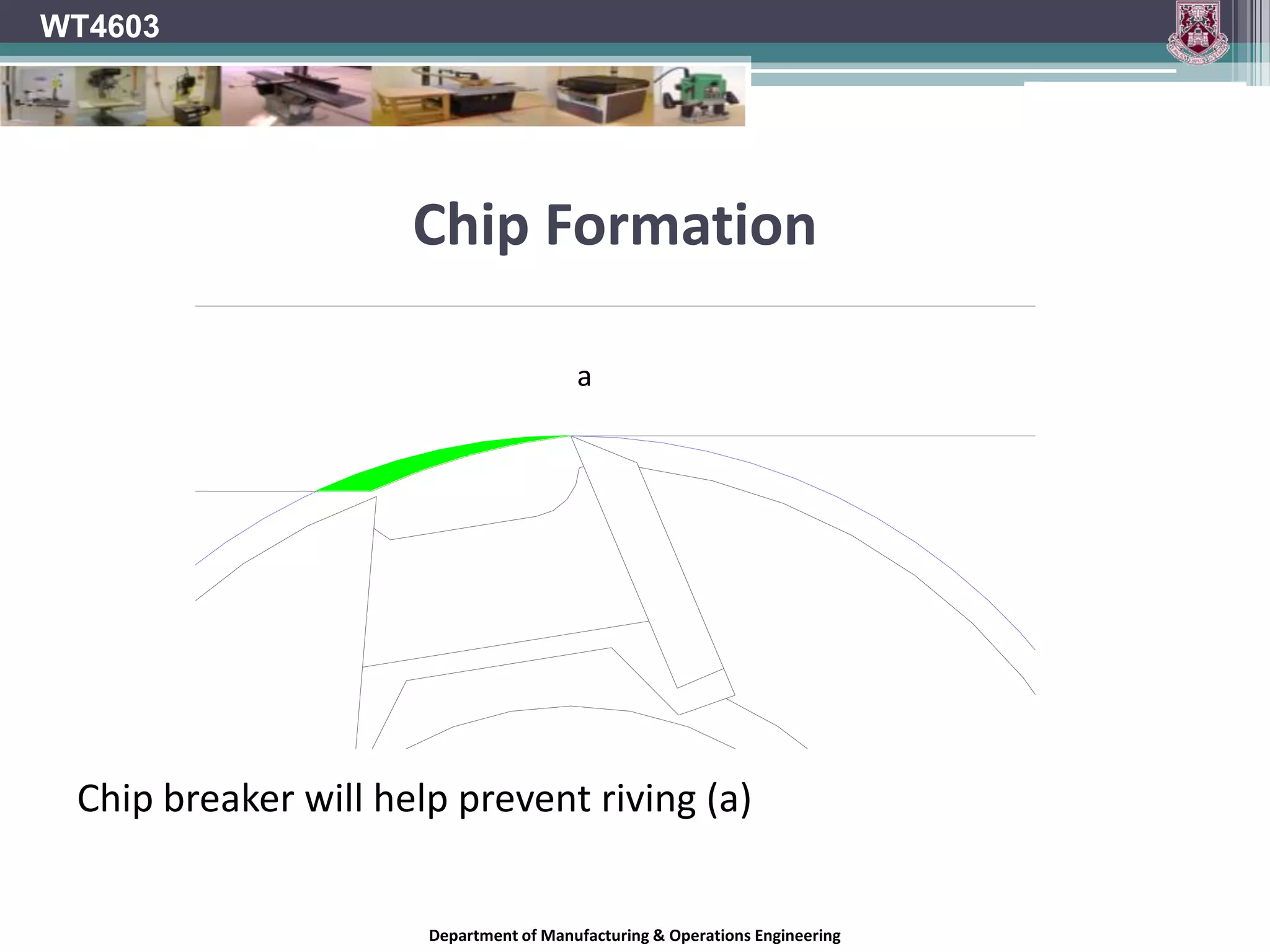
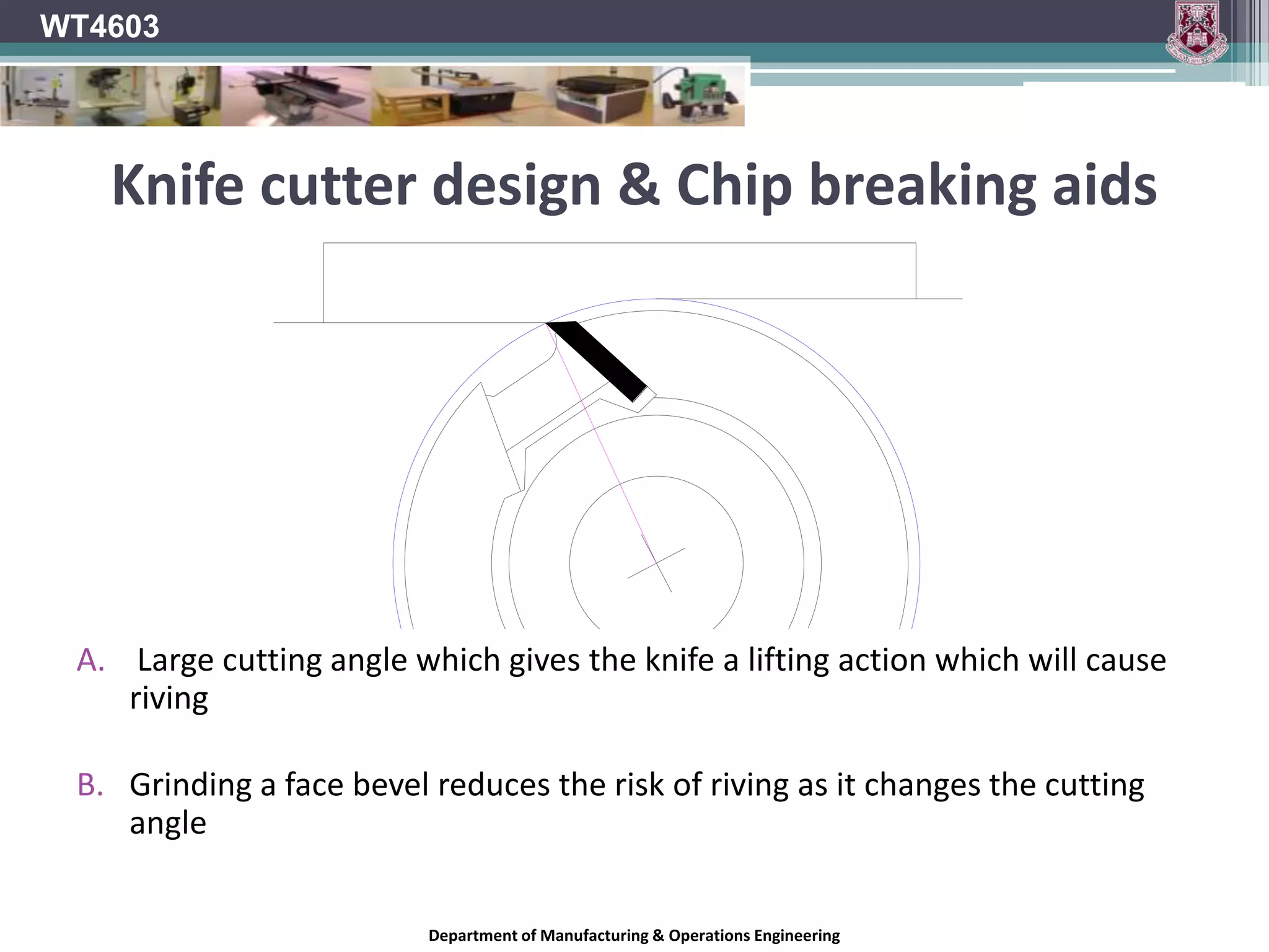
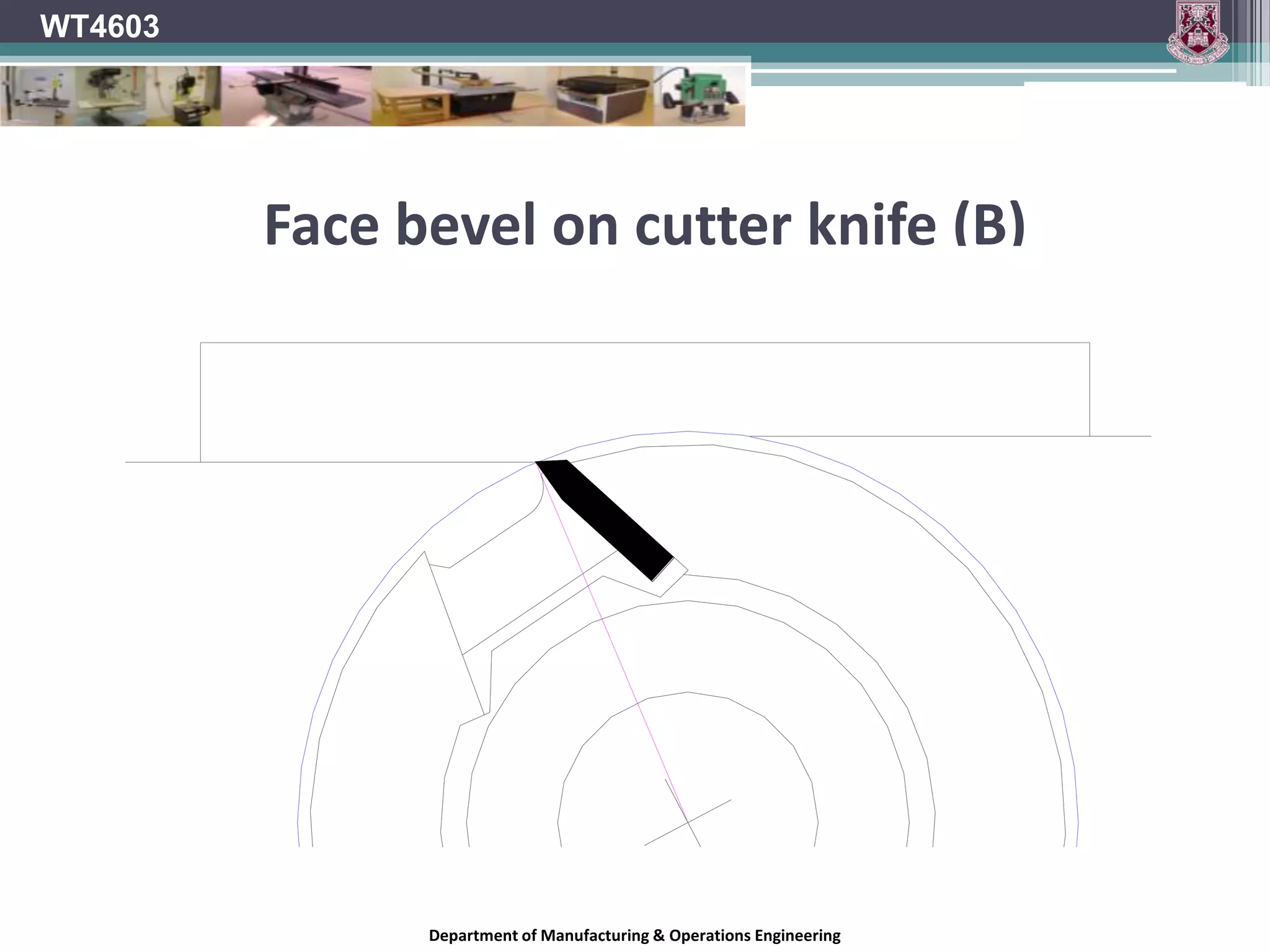
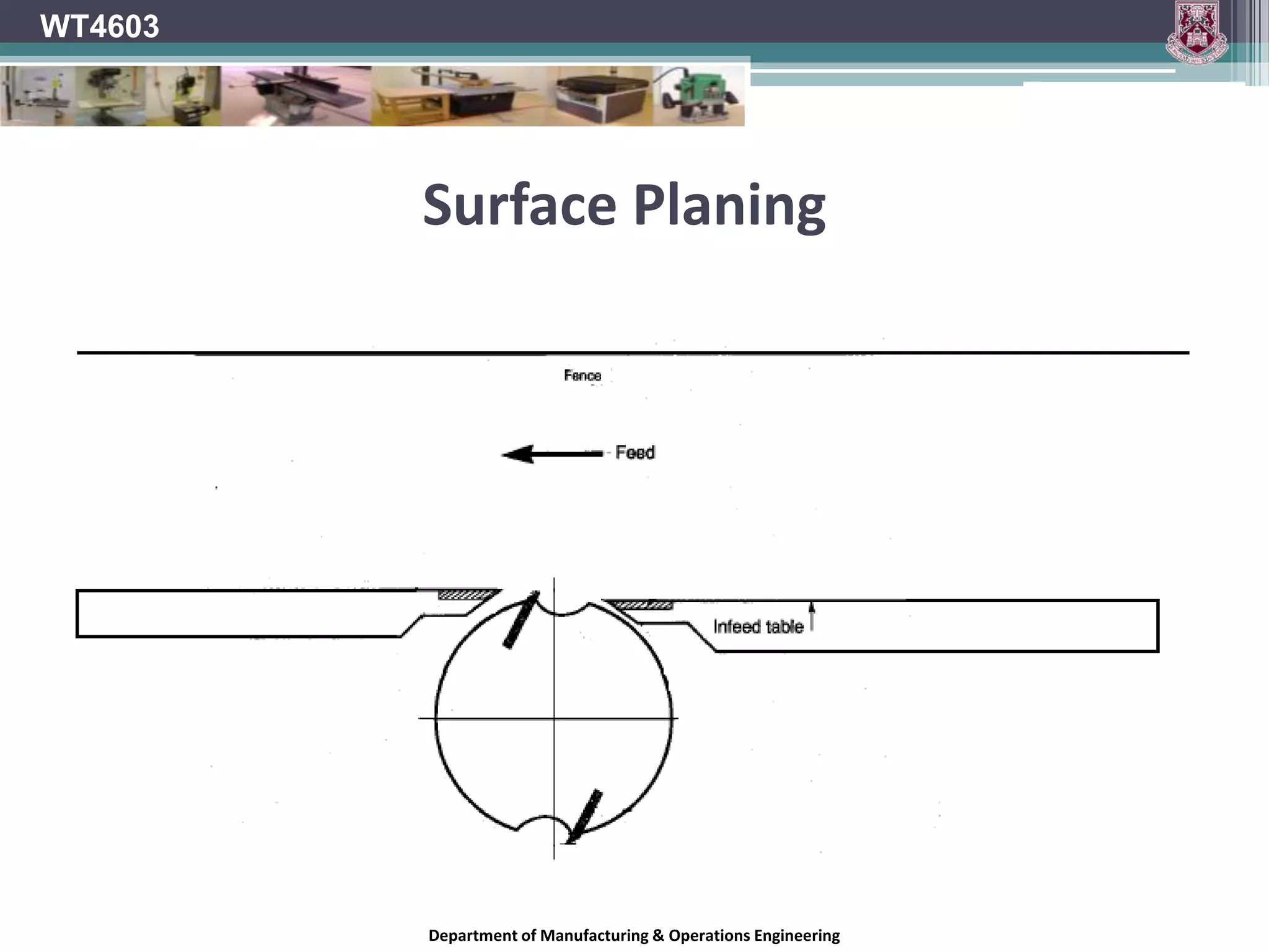
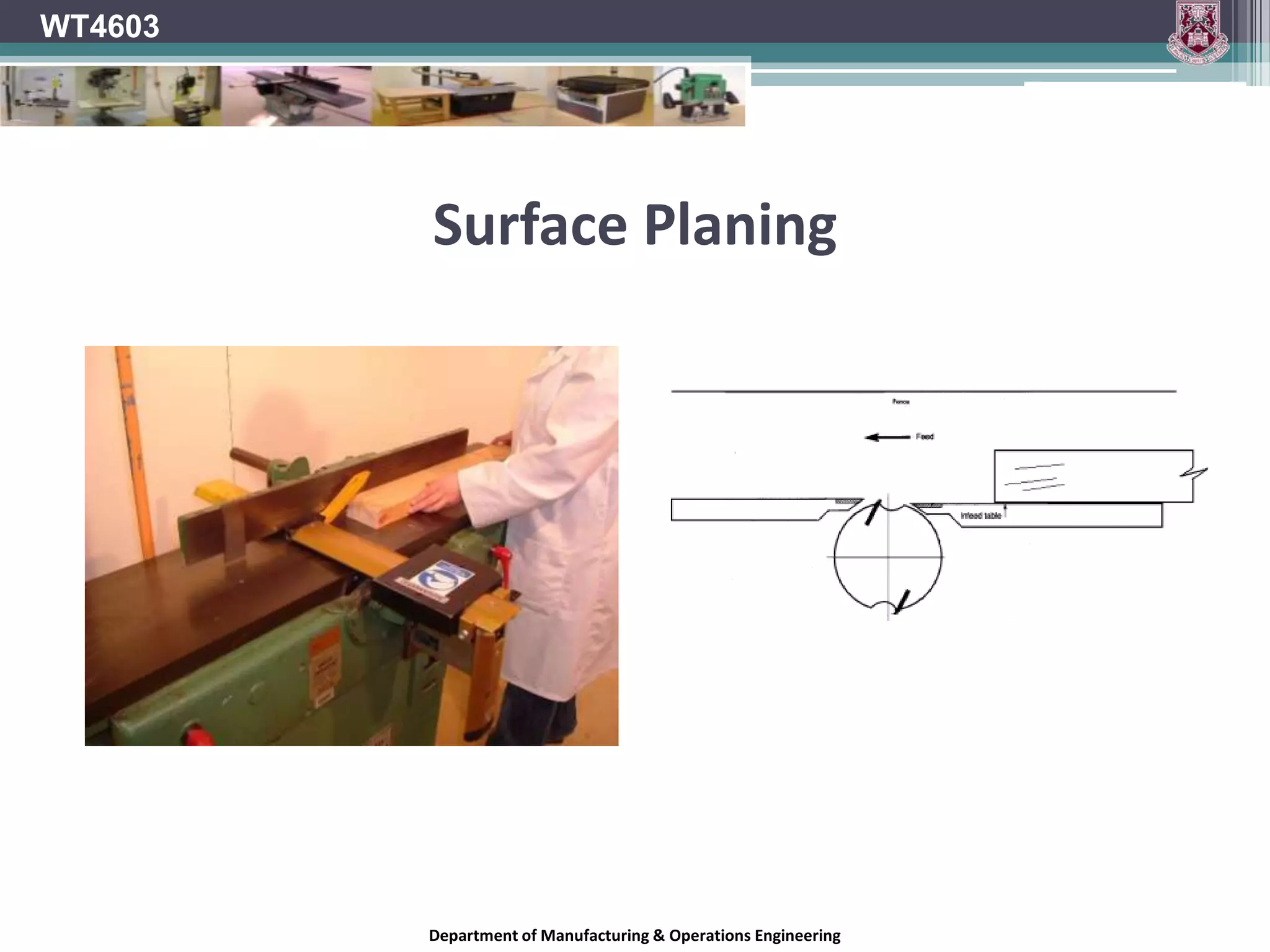
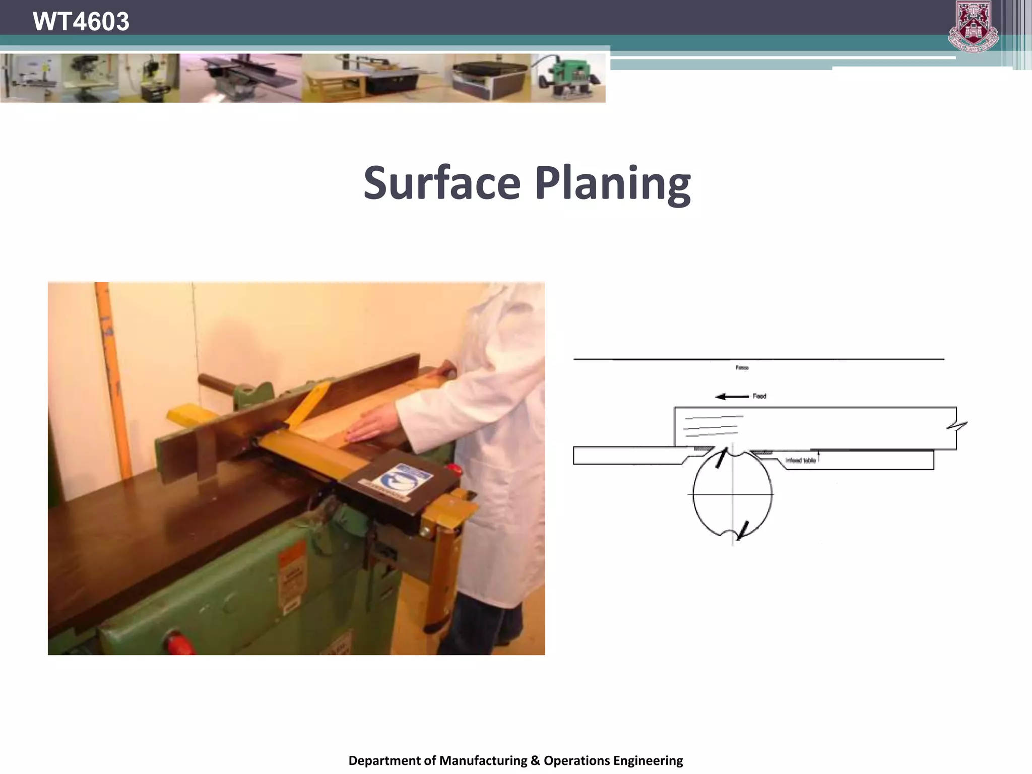
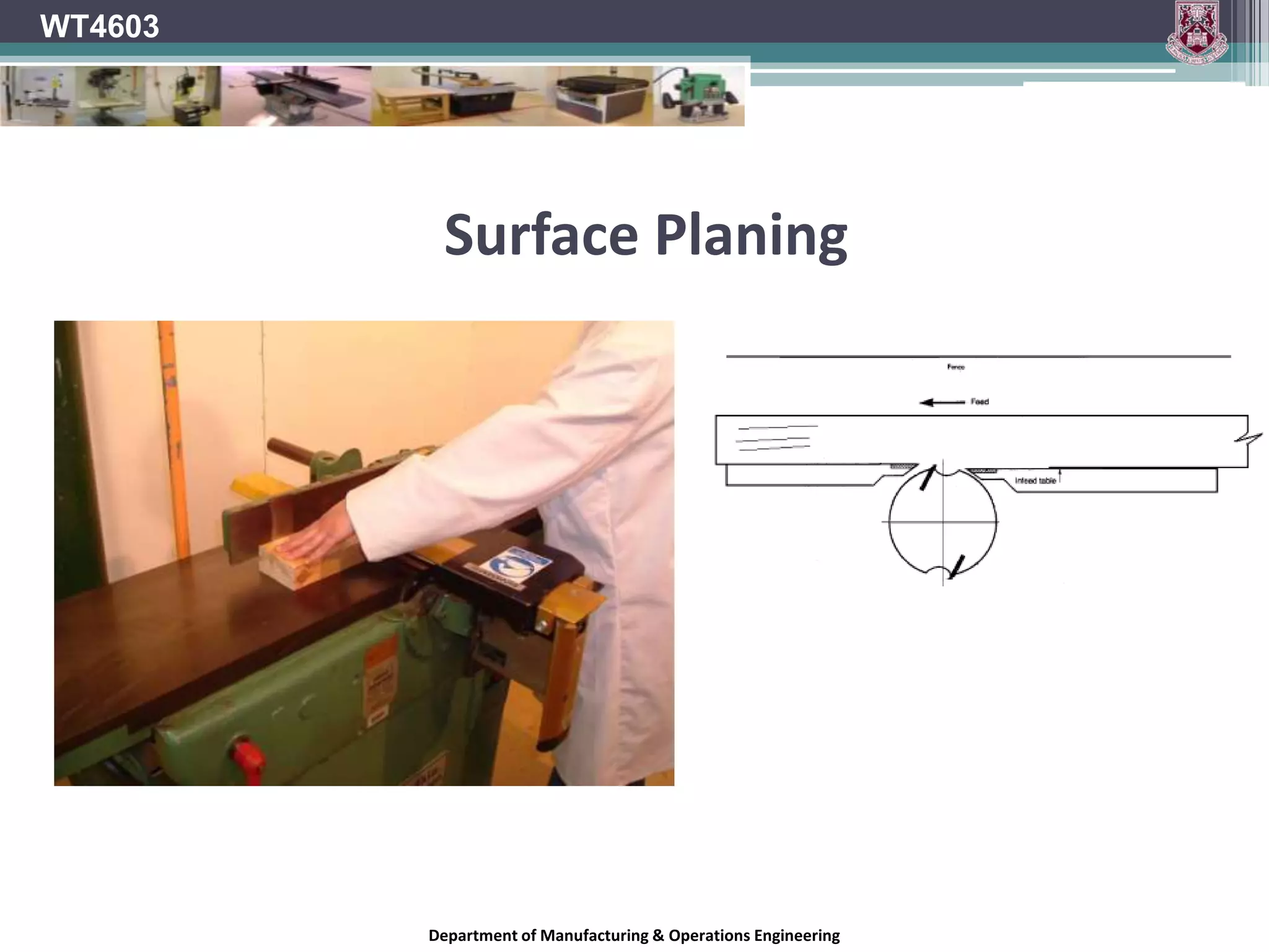
This document provides information on planing machines and their components. It discusses different types of planer knives and the factors to consider when selecting knives, such as the material being processed. It describes various knife materials like chrome vanadium steel, high speed steel, and tungsten carbide. The document outlines knife geometry specifications, including rake angle, bevel angle, clearance angle, and peripheral cutting speed. It also addresses pitch distance, chip formation, riving, cutter projection, and maintenance of planing machines.
Chronological developments in Cutting Tool MaterialsBilal Syed
This is ap resentation showing the developments of cutting tools materials used from early life to present. their materials, properties, advantages, etc.
Please refer this file just as reference material. More concentration should on class room work and text book methodology.
Thermal aspects of Machining, Tool materials, Tool wear Cutting fluids and Machinability.
Unit -1-Theory of Metal Cutting
Manufacturing Technology is much more essential subjects for Mechanical Engineering According that i am prepare study material for Manufacturing Technology-2 UNIT wise ......1 st unit covered more then enough for this materials get wide knowledge from Manufacturing Division.....
All The Best My Dear Hearts
Remaining Units i will update soon ....
Thank you ....
By: Prof.S.Sathishkumar
a cutting tool or cutter is any tool that is used to remove material from the work piece by means of shear deformation. Cutting may be accomplished by single-point or multipoint tools. Single-point tools are used in turning, shaping, planing and similar operations, and remove material by means of one cutting edge. Milling and drilling tools are often multipoint tools. Grinding tools are also multipoint tools. Each grain of abrasive functions as a microscopic single-point cutting edge (although of high negative rake angle), and shears a tiny chip
The International Journal of Engineering and Science (The IJES)theijes
The International Journal of Engineering & Science is aimed at providing a platform for researchers, engineers, scientists, or educators to publish their original research results, to exchange new ideas, to disseminate information in innovative designs, engineering experiences and technological skills. It is also the Journal's objective to promote engineering and technology education. All papers submitted to the Journal will be blind peer-reviewed. Only original articles will be published.
Study of split punch and die of the sheet metal blanking process for length c...eSAT Publishing House
IJRET : International Journal of Research in Engineering and Technology is an international peer reviewed, online journal published by eSAT Publishing House for the enhancement of research in various disciplines of Engineering and Technology. The aim and scope of the journal is to provide an academic medium and an important reference for the advancement and dissemination of research results that support high-level learning, teaching and research in the fields of Engineering and Technology. We bring together Scientists, Academician, Field Engineers, Scholars and Students of related fields of Engineering and Technology
International Journal of Engineering Research and Applications (IJERA) aims to cover the latest outstanding developments in the field of all Engineering Technologies & science.
International Journal of Engineering Research and Applications (IJERA) is a team of researchers not publication services or private publications running the journals for monetary benefits, we are association of scientists and academia who focus only on supporting authors who want to publish their work. The articles published in our journal can be accessed online, all the articles will be archived for real time access.
Our journal system primarily aims to bring out the research talent and the works done by sciaentists, academia, engineers, practitioners, scholars, post graduate students of engineering and science. This journal aims to cover the scientific research in a broader sense and not publishing a niche area of research facilitating researchers from various verticals to publish their papers. It is also aimed to provide a platform for the researchers to publish in a shorter of time, enabling them to continue further All articles published are freely available to scientific researchers in the Government agencies,educators and the general public. We are taking serious efforts to promote our journal across the globe in various ways, we are sure that our journal will act as a scientific platform for all researchers to publish their works online.
EXPERIMENTAL INVESTIGATION AND DESIGN OPTIMIZATION OF END MILLING PROCESS PAR...IAEME Publication
Monel 400 is a precipitation hard enable, Nickel copper alloy with corrosion resistance. Typical applications for Monel 400 include fasteners, springs, chain, pump, impeller and Valve components due their excellent Mechanical properties. The continuous development of carbide milling cutter and its coating technology are great concern with manufacturing Environment. CBN coating play an important role in milling cutter to produce better surface finish and tool life with minimum cost. In this paper deals investigation of End Milling operation of Monel 400 plates with different process parameters like spindle speed, feed rate and depth of cut and to find optimal machining conditions of minimum surface roughness(Ra), Material removal designed and conducted based on design of Experiments using L9 orthogonal array and Optimized by Taguchi Method.
Cutting Parameters Optimization in Milling Of P – 20 Tool Steel And EN31B IOSR Journals
The objective of the paper is to obtain an optimal setting of CNC machining process parameters,
cutting speed, feed rate resulting in optimal values of the feed and radial forces while machining P – 20 tool
steel and EN31B with TiN coated tungsten carbide inserts. The effects of the selected process parameters on the
chosen characteristics and the subsequent optimal settings of the parameters have been accomplished using
Taguchi’s parameter design approach.The process parameters considered are – Cutting speed 3000rpm,
2500rpm and 2000rpm. Feed rate 200mm/min, 300mm/min and 400mm/min and depth of cut is 0.2mm.The
effect of these parameters on the feed force, radial force are considered for analysis.The analysis of the results
shows that the optimal settings for low values of feed and radial forces are high cutting speed, low feed rate and
depth of cut.The thrust force and feed force are also taken experimentally using dynamometer for above Cutting
speeds, feed rate and depth of cut. The optimal values for speed, feed rate and depth of cut are taken using
Taguchi technique.Taguchi methods are statistical methods developed by Genichi Taguchi to improve the
quality of manufactured goods, and more recently also applied to, engineering, biotechnology, marketing and
advertising.Process used in this project is milling process. Machine selected is Vertical milling center. Machine
model selected is BFW Agni 45. Modeling is done in Pro/Engineer and analysis is done in ANSYS.
Turning plays most important role in Machining and Turning is the form of machining process which uses a single-point cutting tool for material removal,from this slide we can get the importance of turning.
The intention of this report is to briefly, explain some of the machining operations that are involved in the process of TURNING, these are: Cutting Speed, Depth of Cut, Feed Rate and Spindle Speed.
Also demonstrated will be the mathematical calculations involved in the same process, using various equations.
This slide contains theoritical and analytical study about "about abrasive water jet machining process" and it has also discription about " OMAX 60120 abrasive water jet machine.Here analytical stydy is done with mainly ss-304 material.
Welcome to International Journal of Engineering Research and Development (IJERD)IJERD Editor
call for paper 2012, hard copy of journal, research paper publishing, where to publish research paper,
journal publishing, how to publish research paper, Call For research paper, international journal, publishing a paper, IJERD, journal of science and technology, how to get a research paper published, publishing a paper, publishing of journal, publishing of research paper, reserach and review articles, IJERD Journal, How to publish your research paper, publish research paper, open access engineering journal, Engineering journal, Mathemetics journal, Physics journal, Chemistry journal, Computer Engineering, Computer Science journal, how to submit your paper, peer reviw journal, indexed journal, reserach and review articles, engineering journal, www.ijerd.com, research journals
2019 Design & Communication Graphics (D.C.G.) Revision Notes covering the majority of the DCG syllabus through relevant exam solutions. Feel free to use these notes for study purposes only. Encrypted video links will not work through this platform but the notes should be clear enough to assist you in your understanding and comprehension of DCG learning areas. Best of luck to all students doing Irish Leaving Certificate exams this June (2018).
2018 Design & Communication Graphics (D.C.G.) Revision Notes covering the majority of the DCG syllabus through relevant exam solutions. Feel free to use these notes for study purposes only. Encrypted video links will not work through this platform but the notes should be clear enough to assist you in your understanding and comprehension of DCG learning areas. Best of luck to all students doing Irish Leaving Certificate exams this June (2018).
A Sample of Part A, Outputs 1 - 6, of this years DCG 2017/18 Leaving Certificate project. The document is intended for study purposes only. Remember Output 4 is not a hard-copy Output and is therefore not included in the document. The reference bibliography has also been excluded in this case but please ensure you reference sources in your own research.
FREE LEAVING CERTIFICATE 2017 CONSTRUCTION STUDIES QUESTION 1 NOTESJOE LYSTER
The notes are relevant to Higher Level Leaving Certificate Construction Studies Question 1 - Scale section drawing building detail. Feel free to use as you wish. Best of luck.
The notes offer advice regarding the Irish Post-Primary Junior Certificate Technical Graphics examination. These notes are intended for study purposes only. Not all of the syllabus areas are represented in these notes.
Model Attribute Check Company Auto PropertyCeline George
In Odoo, the multi-company feature allows you to manage multiple companies within a single Odoo database instance. Each company can have its own configurations while still sharing common resources such as products, customers, and suppliers.
How to Make a Field invisible in Odoo 17Celine George
It is possible to hide or invisible some fields in odoo. Commonly using “invisible” attribute in the field definition to invisible the fields. This slide will show how to make a field invisible in odoo 17.
Synthetic Fiber Construction in lab .pptxPavel ( NSTU)
Synthetic fiber production is a fascinating and complex field that blends chemistry, engineering, and environmental science. By understanding these aspects, students can gain a comprehensive view of synthetic fiber production, its impact on society and the environment, and the potential for future innovations. Synthetic fibers play a crucial role in modern society, impacting various aspects of daily life, industry, and the environment. ynthetic fibers are integral to modern life, offering a range of benefits from cost-effectiveness and versatility to innovative applications and performance characteristics. While they pose environmental challenges, ongoing research and development aim to create more sustainable and eco-friendly alternatives. Understanding the importance of synthetic fibers helps in appreciating their role in the economy, industry, and daily life, while also emphasizing the need for sustainable practices and innovation.
Macroeconomics- Movie Location
This will be used as part of your Personal Professional Portfolio once graded.
Objective:
Prepare a presentation or a paper using research, basic comparative analysis, data organization and application of economic information. You will make an informed assessment of an economic climate outside of the United States to accomplish an entertainment industry objective.
Biological screening of herbal drugs: Introduction and Need for
Phyto-Pharmacological Screening, New Strategies for evaluating
Natural Products, In vitro evaluation techniques for Antioxidants, Antimicrobial and Anticancer drugs. In vivo evaluation techniques
for Anti-inflammatory, Antiulcer, Anticancer, Wound healing, Antidiabetic, Hepatoprotective, Cardio protective, Diuretics and
Antifertility, Toxicity studies as per OECD guidelines
The French Revolution, which began in 1789, was a period of radical social and political upheaval in France. It marked the decline of absolute monarchies, the rise of secular and democratic republics, and the eventual rise of Napoleon Bonaparte. This revolutionary period is crucial in understanding the transition from feudalism to modernity in Europe.
For more information, visit-www.vavaclasses.com
Welcome to TechSoup New Member Orientation and Q&A (May 2024).pdfTechSoup
In this webinar you will learn how your organization can access TechSoup's wide variety of product discount and donation programs. From hardware to software, we'll give you a tour of the tools available to help your nonprofit with productivity, collaboration, financial management, donor tracking, security, and more.
Honest Reviews of Tim Han LMA Course Program.pptxtimhan337
Personal development courses are widely available today, with each one promising life-changing outcomes. Tim Han’s Life Mastery Achievers (LMA) Course has drawn a lot of interest. In addition to offering my frank assessment of Success Insider’s LMA Course, this piece examines the course’s effects via a variety of Tim Han LMA course reviews and Success Insider comments.
Acetabularia Information For Class 9 .docxvaibhavrinwa19
Acetabularia acetabulum is a single-celled green alga that in its vegetative state is morphologically differentiated into a basal rhizoid and an axially elongated stalk, which bears whorls of branching hairs. The single diploid nucleus resides in the rhizoid.
6. Surface Planer WT4603 Planers can have 2,3,4,6……. Cutter knives. Most smaller machines such as those found in schools will have 2,3 or 4 knives. Department of Manufacturing & Operations Engineering
7. Surface Planer WT4603 Knives can be made from Chrome Vanadium steel alloy. This is suitable for machining softwoods and non abrasive hardwoods. However with advances in machining technology better materials have been developed to machine wood and wood composites. Chrome Vanadium knives dull quickly on harder more dense material. This requires more sharpening, setting up and leads to a lot of time wastage. Department of Manufacturing & Operations Engineering
8. Surface Planer WT4603 High Speed Steel (HSS) is a cobalt steel alloy with a small percentage of Tungsten added. It is more suitable for machining all types of wood than the chrome steel compounds. Department of Manufacturing & Operations Engineering
9. Surface Planer WT4603 Abrasive stock should be machined using solid or tipped cutters. Tungsten Carbide (TC) is the best tool compound for machining manufactured boards. For general work HSS cutters are preferred to TC Cutters can be re-sharpened easily. A keener edge can be achieved on HSS giving a better finish Department of Manufacturing & Operations Engineering
10. Surface Planer WT4603 The reason for this is that steel compounds are smelted and shaped by rolling and forging while the metal is close to melting point. The molecules of the compound flow and align themselves in response to this pressure giving the material maximum strength and edge holding capabilities Department of Manufacturing & Operations Engineering
11. WT4603 Surface Planer Tungsten carbide is a sintered compound. The fine grain powder from which the cutter will eventually will be made is compressed into a mould ( the ‘blank’ un-edged cutter required) under extremely high temperature (1500C) and pressure to form a solid block. Tungsten does not flow – it retains a granular structure and will chip rather than deform if abused. Department of Manufacturing & Operations Engineering
12. Surface Planer WT4603 Because if its brittle nature TC cutters require a more obtuse sharpness angle than the HSS cutters (more support for the cutting edge). This makes it less satisfactory for cutting softwoods than HSS knives which can be ground to a more acute cutting angle. Department of Manufacturing & Operations Engineering
14. WT4603 Knife Cutter geometry Rake or Cutting angle Angle created between the face of the cutting knife and the centre of the cutter block Can have a wide range Softwoods 27° to 35 ° Hardwoods 15° to 25 ° Department of Manufacturing & Operations Engineering
15. WT4603 Knife Cutter Geometry Bevel or Lip Angle Angle formed to give the cutting edge Minimum of usually 35° Greater for tipped cutters Department of Manufacturing & Operations Engineering
16. WT4603 Knife Cutter Geometry Clearance Angle Angle formed between a line tangential to cutting circle and the bevel angle of the knife Must be present Has a bearing on the life of the cutting edge Usually 10° to 15° Department of Manufacturing & Operations Engineering
17. WT4603 Knife Cutter Geometry Peripheral Cutting Speed A constant speed in the range of 35-45 m/s will give best results Increase in speed may cause loss of dynamic balance due to vibrations Poor finish Increased noise levels Department of Manufacturing & Operations Engineering
18. WT4603 Pitch distance Combination of a rotary cut and a linear feed will leave the surface of the material with a series of arcs on it called Curtate Trochoids The pitch and depth of these arcs will determine how smooth the surface finish will be Department of Manufacturing & Operations Engineering
19. Department of Materials Science & Technology University of Limerick WT4603 Pitch Distance 2mm to 3mm for non obvious joinery and painted external work. 1mm to 1.5 mm for internal painted work. 0.5mm to 1mm for hardwood joinery and furniture. Department of Manufacturing & Operations Engineering
20. WT4603 Pitch Distance The SI unit of time is the second , but the minute is acceptable. Feed rate on wood working machines is expressed in metres per minute. (m/min) The formula for the pitch of the cutter marks is given by: f p = ------- nR where p = pitch of cutter mark f = feed rate n = number of effective cutters R = revolutions per minute of block Department of Manufacturing & Operations Engineering
21. Pitch Distance WT4603 The unit for “p” will be metres (m) f m/min m min p = ---- = --------- = ----- x ------ = m nR 1/min min 1 Department of Manufacturing & Operations Engineering
22. WT4603 Pitch Distance Problem 1 Calculate the cutter pitch of a 4 cutter block revolving at 4200 rev/min with a feed speed of 24m/min. F 24 24 p = ------- = ------------ = --------- = 0.0014m = 1.4mm nR 4 x 4200 16800 (Internal painted work) Department of Manufacturing & Operations Engineering
23. Pitch Distance WT4603 If a graded surface is specified and the machine has a multi-speed feed gearbox, the same formula is used but “f” is expressed in terms of n ,p, and R. f p = ------- f = nRp nR Department of Manufacturing & Operations Engineering
24. Pitch Distance Problem 2 From a cutter block which rotates at 4200 rev/min and has two cutting knives, a surface finish of a 4mm pitch is required. At what speed should the feed gearbox be set. f = nRp = 2 x 0.004 x 4200 = 33.6 m/min WT4603 Department of Manufacturing & Operations Engineering
27. Riving WT4603 Cracking occurs below the cut depth Department of Manufacturing & Operations Engineering
28. WT4603 A On the surface planer the in-feed table (A) acts as chip breaker and the downward pressure exerted by the operator also makes it act as the pressure bar. Department of Manufacturing & Operations Engineering
36. Easier and quicker maintenanceDepartment of Manufacturing & Operations Engineering
37. WT4603 Circular cutter block Clamping bolts are in tension Department of Manufacturing & Operations Engineering
38. WT4603 Knife clamping mechanism Department of Manufacturing & Operations Engineering
39. WT4603 Knife clamping mechanism Department of Manufacturing & Operations Engineering
40. Cutter projection WT4603 Use of a limiter to achieve limited cutter projection Department of Manufacturing & Operations Engineering
41. Cutter design WT4603 Cutters should preferably be designed to be used in dimensionally similar pairs, formed to the same profile. Pairs should be mounted directly opposite one another. The manufacturer should ensure that instructions on balancing the pairs of cutters after grinding are given to the user. Department of Manufacturing & Operations Engineering
42. Cutter projection WT4603 The design of cutter blocks should, as far as is practicable, be such as to prevent excessive cutter projection. Where the mounting arrangement permits projection which could subject the cutter to unsafe stresses, the maximum permissible projection for given cutter types should be specified in the user’s instructions. Department of Manufacturing & Operations Engineering
43. Hand-fed machines WT4603 For machines designed for hand-fed operations, where cutters are necessarily exposed, the use of chip limiting cutters should be recommended For other hand and semi-mechanical feed operations, cutter blocks should have as little cutter projection as is practicable. Department of Manufacturing & Operations Engineering
46. rise and fall tableDepartment of Manufacturing & Operations Engineering
47. Surface Planer WT4603 The grinding angle of a cutter can vary between 30 to 35 This is increased to 40 for hardwoods (cutting edge lasts longer) Department of Manufacturing & Operations Engineering
48. WT4603 Surface Planer Overheating May produce micro cracks in the cutting edge which can run into gaps when the cutter is used. May cause the cutter to bow due to expansion. Department of Manufacturing & Operations Engineering
49. WT4603 Surface Planer Overheating can be avoided By taking light cuts. By ensuring that the grind wheel is ‘dressed’ when required to ensure that the face is open and not glazed when grinding the knives. By using a ‘soft’ grinding wheel on HSS cutters – the soft structure of the wheel allows its grains to break away as soon as they are blunt revealing sharper ones. By wet grinding – this is the grinding of cutters while partially submerged in a mixture of water and soluble oil. The water is a coolant to prevent frictional heat developing and to disperse it should it occur. The oil prevents rust in the cutters and it provides a degree of cutting lubrication. Department of Manufacturing & Operations Engineering
50. WT4603 Surface Planer Setting Cutters in Block Before setting the following points should be checked. The out feed table and cutter block must be clean and free from dust resin. Method of adjusting cutters. Area where setting device is used from should be free from resin and damage. Straightness of cutters. Cutters correctly balanced both in weight and end for end. Department of Manufacturing & Operations Engineering
51. WT4603 Surface Planer Setting devices There are a number of cutter setting devices. This device and procedure will often be supplied with the machine. They can be loosely placed into the following four categories: Bridge device Precision cutter setter device Pin locater device Wooden straight edge device Cutters require accurate setting in the block because if the knives are not revolving in the same cutting circle a poor finish will be produced. Department of Manufacturing & Operations Engineering
52. WT4603 Setting Cutter Knives Setting of knives will greatly depend on the type of cutter block Knife cutter projection Chip breaker Knife parallel to table All knives in the same peripheral cutting circle (Refer to machine manual for setting) Department of Manufacturing & Operations Engineering
53. WT4603 Setting Planer Knives When planing wooden material a number of factors combine to generate the flat surface. Number of cutting knives in the block Speed of the revolving block Feed speed of the material Knife cutter design Chip breaking aids Nature and species of the material Department of Manufacturing & Operations Engineering
54. Knife cutter design & Chip breaking aids These factors combine to produce an acceptable surface finish Tip of the cutter splits away the chip The chip is forced away from the stock and up along the face of the cutter which is exerting a tearing effect on the grain fibre As the knife exits the stock the chip is either cut or will “rive” or tear deeply along the grain line and lift as a long heavy splinter WT4603 Department of Manufacturing & Operations Engineering
55. Knife cutter design & Chip breaking aids The cutter projection and the shape of the block face cause the severed chip to bend back causing a crack across its width This makes long grain riving less likely (Chip breaker not shown) WT4603 Department of Manufacturing & Operations Engineering
56. WT4603 Knife cutter design & Chip breaking aids Sharp tooling (a) will aid in the chip bending back and cracking across its width Blunt tooling (b) will aid riving Department of Manufacturing & Operations Engineering
57. WT4603 Chip Formation Before knife makes its cut Department of Manufacturing & Operations Engineering
58. WT4603 Chip Formation Chip to be formed Department of Manufacturing & Operations Engineering
59. WT4603 Chip Formation a Chip breaker will help prevent riving (a) Department of Manufacturing & Operations Engineering
60. WT4603 Knife cutter design & Chip breaking aids Large cutting angle which gives the knife a lifting action which will cause riving Grinding a face bevel reduces the risk of riving as it changes the cutting angle Department of Manufacturing & Operations Engineering
61. WT4603 Face bevel on cutter knife (B) Department of Manufacturing & Operations Engineering
76. WT4603 Hand Router Consists of cutter rotating at between 800 to 30,000 RPM being driven by a vertically mounted motor set on a flat based framework Department of Manufacturing & Operations Engineering
79. WT4603 Hand Router Cutting grooves Cutting rebates Cutting slots and recesses Cutting beads or mouldings Cutting dovetails Cutting dovetailed slots and grooves Edge trimming Profiling (jigs/formers) Department of Manufacturing & Operations Engineering
80. WT4603 Hand Router: Power Large powerful routers are heavy and can be difficult to handle for light work. Generally in schools the type of work that the router will have to perform will be light to medium work. As a rough guide to classifying routers: 400 W to 600W are for light duty 750 W to 1200W are for medium duty 1250 W upwards are for heavy duty Department of Manufacturing & Operations Engineering
82. WT4603 Collet A tapered sleeve that is made in a number of segments that is used to hold the shaft of a cutter or bit. Department of Manufacturing & Operations Engineering
83. WT4603 Collet needs to be cleaned regularly Must prevent rust Must prevent wear Can clean with solvents but must spray with WD40 afterwards Department of Manufacturing & Operations Engineering
89. Cutters should be cleaned regularly with white spirit and fine scraper to remove dirt, resin and debris.
90. Cutters should also be inspected for damage prior to operating.Department of Manufacturing & Operations Engineering
91. WT4603 Cutters (Router bits) A router bit is a tool for woodworking giving a quality finish to the material. It cuts wood providing a way to give a clean and even a decorative edge to woodwork. The following is some basic information about router bits to get you started in your woodworking efforts. Here are the there main parts of a router bit: The shank- the part of the router bit that is inserted into the collet (the sleeve of the router). The cutting edge- this part cuts and removes the wood. They are available in several sizes and shapes. The pilot- the guide for the router in order to make a correct cut. It can be an extension of the shank or a ball bearing attachment. Department of Manufacturing & Operations Engineering
92. WT4603 Cutters (Router bits) Cutters can have disposable or interchangeable profiles. Department of Manufacturing & Operations Engineering
93. WT4603 Cutters (Router bits) Cutter diameter will have a direct effect on the power required form the router motor. Department of Manufacturing & Operations Engineering
94. WT4603 Cutter selection & feed direction Department of Manufacturing & Operations Engineering
95.
96. If you push the router into the material from position (A), the router will pull to your left.
97. If you pull the router into the material toward you from position (B), the router will pull to your right.
98. This occurs as the cutter will climb on the material in front of the cutting edge.
99. This motion must be utilised when using guide fences.Department of Manufacturing & Operations Engineering
100. WT4603 Feed direction & the fence To process a straight housing or trench you can use a straight edge guide (A) or the guide fence that is supplied with the router(B). Department of Manufacturing & Operations Engineering
103. The router will try to pull to the operators left hand side.
104. With the fence clamped on the left of the router, the router will push against it as it is fed into the material.(Green arrows)
105. If the fence were on the right hand side (when viewed from the operators position) of the router, it would pull away from the fence and result in the trench being crocked.Department of Manufacturing & Operations Engineering
111. Feeding the router in the opposite direction will cause any dust to be blown away from the operator.
112. This will require the guide fence to be set up on the right hand side of the router and operator. F Feed direction & the fence Department of Manufacturing & Operations Engineering
113. WT4603 Guide fence Guide fence fixed to the router. Can be fixed from either side. Department of Manufacturing & Operations Engineering
114. WT4603 F P Using the guide fence When feeding the router forward (F) the router will tend to pull to the operators left hand side. The fence should be set on the right hand side of the router. When the cutter engages in the material it will pull to the left as indicated by the green arrow (P) and keep the fence tight against the materials edge. Material should be securely calmped or placed on a non-slip router mat. Department of Manufacturing & Operations Engineering
115. WT4603 Profiles can be processed on material using templates. Templates can have the required profile as an internal shape or an external profile. To process the section marked (A) In the photo an internal template can be used to guide the router to produce the profile. Feed direction can be established using the right hand rule. Department of Manufacturing & Operations Engineering
117. WT4603 Using the template guide Fit the template guide to the router base plate. Set cutter plunge depth. Place over template at the starting position (A). Switch on the router and then plunge to depth (B). Feed router in a clockwise direction. Department of Manufacturing & Operations Engineering
118. WT4603 ROUTER PULLS TO THE LEFT FENCE PULLED TOWARDS WORKPIECE FEED DIRECTION Router Station 1 Carry out the following operations: Isolate the router. Select V- groove cutting bit. Fit the bit in the router securely. Set the depth of the cut to 3mm. Machine the profile shown on the drawing using the guide fence. (Note: Guide fence is set. Do not adjust.) Isolate the router. Remove the cutter from the router. Department of Manufacturing & Operations Engineering
119. WT4603 Router Station 3 Carry out the following operations: Isolate the router. Select Ø 6mm cutting bit. Fit the bit in the router securely. Set the depth of the cut to 5mm. Set the depth turret to machine to a depth of 10mm on the second pass. Fit the guide fence to the router. Set the guide fence to the dimension shown on the drawing. Machine the profile shown on the drawing using the guide fence. Isolate the router. Remove the guide fence and Ø 6mm cutting bit from the router. Department of Manufacturing & Operations Engineering
120. WT4603 Router Station 4 Carry out the following operations: Isolate the router. Select Ø 12mm cutting bit cutting bit. Fit the bit in the router securely. Fix the template guide to the base of the router. Set material in the template. Set the depth of the cut to 5mm. Set the depth turret to machine to a depth of 10mm on the second pass. Machine the profiles of the template using the template guide. Isolate the router. Remove the template guide and Ø 12mm cutting bit from the router. Department of Manufacturing & Operations Engineering
121.
122. You will label both pieces B1 and B2, respectively.B1 Table Top 145 1020 Back/Side Rails & Drawer Front B2 145 1020 Department of Manufacturing & Operations Engineering
123. WT4603 WEEK 4: LABS Component B Cutting List Department of Manufacturing & Operations Engineering