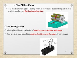
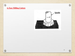
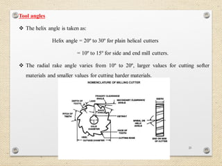
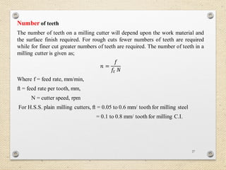
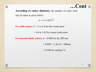
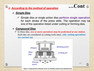
DEBRE MARKOS UNIVERSITY
COLLEGE OF TECHNOLOGY
Mechanical Engineering Department
Tools jigs and die design
By: Mulatu M. October 2017 1
CHAPTER ONE
INTRODUCTION TO TOOL DESIGN
2
 Tool design is a specialized area of manufacturing engineering
comprising the analysis, planning, design, construction, and
application of tools, methods, and procedures necessary to increase
manufacturing productivity.
 To carry out these responsibilities, today’s tool designer must have a
working knowledge of machine shop practices, toolmaking
procedures, machine tool design, manufacturing procedures and
methods, as well as the more conventional engineering disciplines of
planning, designing, engineering graphics and drawing, and cost
analysis.
3
 The main objective of a tool designer is to increase production while
maintaining quality and lowering costs.
 The tool designer must realize the following goals;
 Reduce the overall cost to manufacture a product by making acceptable
parts at the lowest cost.
 Increase the production rate by designing tools to produce parts as
quickly as possible.
 Maintain quality by designing tools to consistently produce parts with the
required precision.
 Reduce the cost of special tooling by making every design as cost-
effective and efficient as possible.
 Design tools to be safe and easy to operate.
 Select the materials that will give adequate tool life.
OBJECIVES TOOL DESIGNER’S
4
 Tool designers are responsible for creating a wide variety of special tools. They
must be familiar with;
 Cutting tools, tool holders, and cutting fluids;
 Machine tools;
 Jigs and fixtures;
 Gages and measuring instruments;
 Dies for sheet-metal cutting and forming and;
 Dies for forging, upsetting, cold finishing, and extrusion
TOOL DESIGNER RESPONSIBILITIES
5
 In most cases, the size of the employer or the type of product will
determine the exact duties of each designer.
 Larger companies with several product lines may employ many tool
designers;
 In this situation, each designer may have an area of specialization,
such as die design, jig and fixture design, gage design, or any similar
tool design area.
 In smaller companies, however, one tool designer may have to do all
tool designs, as well as other tasks in manufacturing.
…Cont
PROCESSES OF THE TOOL DESIGN
6
The design process consists of five basic steps;
1. Statement and analysis of the problem;
2. Analysis of the requirements;
3. Development of initial ideas;
4. Development of design alternatives, and
5. Finalization of design ideas.
7
 The first step in the design of any tool is to define the problem as it
exists without tooling.
1. Statement of the Problem
 After the problem, has been isolated, the requirements, including function,
quality, cost, due date, and other related specifics can be used to determine the
parameters within which the designer must work.
2. Analysis of the Requirements
…Cont
8
Every tool that is designed must;
 Perform certain functions;
 Meet certain minimum precision requirements;
 Keep costs to a minimum;
 Be available when the production schedule requires it;
 Be operated safely;
 Meet various other requirements such as adaptability to the machine on
which it is to be used, and
 Have an acceptable working life.
9
 Initial design ideas are normally conceived after an examination of
the preliminary data.
 This data consists of the part print, process sheet, engineering
notes, production schedules, and other related information.
3. Development of Initial Ideas
4. Development of Design Alternatives
10
Table 1.1 Basic pattern for tool analysis
11
5. Finalization of Design Ideas
 Once the initial design ideas and alternatives are determined, the tool
designer must analyze each element to determine the best way to
proceed toward the final tool design.
 Generally final details are decided; final drawings are made, and the
tooling is built and tested.
12
Checklist for design considerations
1. Workpiece:
 Size,
 Shape,
 Required accuracy,
 Material type,
 Locating points,
 Locating stability,
 Clamping surfaces and
 Production quantity
…Cont
13
2. Operations
 Types of operations,
 Number of separate operations,
3. Personnel
 Safety equipment,
 Safety regulations and work rules,
 Economy of motion,
 Sequence and
 Inspection requirements
 Operator fatigue,
 Power equipment available and
 Possible automation.
…Cont
14
4. Equipment
 Machine tools,
 Cutting tools,
 Assembly equipment and tools,
 Inspection equipment and tools,
 Equipment availability and scheduling and;
 Plant space required
15
 A tool designer must have a strong background in drafting,
dimensioning, and mechanical drawing to properly present design
concepts to the people who will make the proposed tool.
Mechanical engineering packages like computer-aided design
(CAD), Solidworks, CATIA and ANSYS software’s can be
used for this purpose.
TOOL DRAWINGS
16
 The following are useful points to remember when creating tool
drawings;
• Draw and dimension with due consideration for the person who
will use the drawing to make the item in the tool room.
• Do not crowd views or dimensions.
• Analyze each cut, so that wherever possible the cut can be made
with standard tools.
• Surface roughness must be specified.
• Tolerances and fits to tools need special consideration.
17
18
19
20
DESIGN OF MILLING CUTTER
 Milling is a process of generating machined surfaces by progressively removing a
predetermined amount of material or stock from the workpiece.
 Milling cutters are cutting tools typically used in milling machines or machining
centres to perform milling operations
Types of Milling Cutters
The variety of milling cutters available for all types of milling machines helps
make milling a very versatile machining process.
1. Side Milling Cutter
The side milling cutter has a cutting edge on the sides as well as on the periphery. This
allows the cutter to mill slots.
21
2. Plain Milling Cutter
 The most common type of milling cutter is known as a plain milling cutter. It is
used for producing a flat horizontal surface.
3. End Milling Cutter
 It is employed in the production of slots, keyways, recesses, and tangs.
 They are also used for milling angles, shoulders, and the edges of work pieces.
22
4. Face Milling Cutters
23
Design features
The design features of a milling cutter will be illustrated by considering a plain milling
cutter. The main elements to be considered for the design are:
 size of cutter,
 tool angles,
 number of teeth,
 flutes, and
 material.
24
Size of cutter
The outside diameter of the cutter D depends upon the arbor diameter, d, thickness of the cutter
ring, t, and the height of the cutting tooth, h, or the depth of the flute. It is given as:
𝑫 = 𝒅 + 𝟐𝒕 + 𝟐𝒉
Generally, the cutter diameter, D, is taken about 2.5 to 3 times the arbor diameter.
The arbor is usually selected from the commercially available standard arbor sizes: 16, 22,
27,32, 40, 50 and 60 mm.
 Diameter of plain milling cutters and the depth of cut are also inter related as follows:
D = 60 to 90 mm for depth of cut up to 5 mm.
= 90 to 110 mm for depth of cut up to 8 mm.
= 110 to 150 mm for depth of cut up to12 mm.
 Face width of milling cutter = width of w.p. + (2 to 5) mm.
 Diameter of face milling cutter is selected depending on the width B of the surface to be
milled:
D = (1.06 to 1.10) × B for H.S.S. cutters
= (1.20 to 107.) × B for carbide tipped cutters.
25
Tool angles
 The helix angle is taken as:
Helix angle = 20º to 30º for plain helical cutters
= 10º to 15º for side and end mill cutters.
 The radial rake angle varies from 10º to 20º, larger values for cutting softer
materials and smaller values for cutting harder materials.
26
Width of land
To give strength to the cutting point, a narrow land is provided immediately behind
the cutting edge. This land is ground to the relief angle. Its values are;
Width of land = 0.127 to 0.254 mm for small end mills
= up to 3.2 mm on large diameter cutters
= 0.80 to 1.6 mm (average)
27
Number of teeth
The number of teeth on a milling cutter will depend upon the work material and
the surface finish required. For rough cuts fewer numbers of teeth are required
while for finer cut greater numbers of teeth are required. The number of teeth in a
milling cutter is given as;
𝑛 =
𝑓
𝑓𝑡 𝑁
Where f = feed rate, mm/min,
ft = feed rate per tooth, mm,
N = cutter speed, rpm
For H.S.S. plain milling cutters, ft = 0.05 to 0.6 mm/ tooth for milling steel
= 0.1 to 0.8 mm/ tooth for milling C.I.
28
According to cutter diameter, the number of cutter teeth
may be taken as given below:
𝑛 = 𝐶 × (𝐷)
1
2
For solid cutters: C = 2 to 2.8 for fine tooth cutter
= 0.6 to 1.05 for coarse tooth cutter
For inserted blade cutters, n = 0.04D for d≤ 200 mm
= 0.04D + 2, for D > 200mm
= 0.10D for cutting C.I.
…Cont
29
Power requirements for milling
The total horsepower required at the cutter can be found as;
𝑕 𝑝𝑐 =
(𝑚𝑒𝑡𝑎𝑙 𝑟𝑒𝑚𝑜𝑣𝑎𝑙 𝑟𝑎𝑡𝑒, 𝑐𝑚3)
𝐾
Forces acting on the cutter
From the given conditions the force acting on the cutter (W) may be calculated as:
𝑤 =
60 × 𝐻
𝜋𝑑𝑛
Where 𝑤 = forces acting on the cutter, 𝐻 = power in KW, 𝑛 = the speed in rpm, 𝑑 =
the cutter diameter.
30
Surface cutting speed (Vc)
This is the speed at which each tooth cuts through the material as the tool spins.
Typical values for cutting speed are;
 10m/min to 60m/min for some steels,and
 100m/min and 600m/min for aluminum.
𝑉𝑐 = 𝑆𝜋𝑑
Where 𝑆 is the spindle speed (the rotation speed of the tool)
𝑑 is the diameter of the milling cutter.
31
Metal removal rate
The metal removal rate is given as,
𝑀𝑅𝑅 = 𝑤 × 𝑕 × 𝑓
Where 𝑤 = width of cut, mm; 𝑓 = feed rate
𝑕 = depth of cut, mm
= 3 to 8 mm for roughing
= 0.5 to 1.5 mm for finishing
32
DESIGN OF TOOL LIFE
 Tool life is a measure of the length of time a tool will cut effectively.
Or
 Tool life is defined as the time interval for which tool works satisfactorily
between two successive grinding or re-sharpening of the tool.
 The life of cutting tool depends upon many factors, such as;
 Microstructure of the material being cut,
 Metal removal rate,
 The rigidity of the setup and
 Effects of cutting fluid.
33
From Taylor tool life equation;
𝑣𝑇 𝑛 = 𝐶
Rearranging the above equation, the life of the tool becomes;
𝑇 = (
𝐶
𝑣
)
1
𝑛
Where 𝑣 = cutting speed, 𝑇 = tool life, 𝑛 𝑎𝑛𝑑 𝐶 = are parameters that depend on
feed, depth of cut, work material, tooling material, and the tool life criterion used (𝑛 is
the slope of the plot and 𝐶 is the intercept on the speed axis.
34
DESIGN OF JIGS & FIXTURES
 Some machining operation are so simple which are done quite easily, such
as turning, the job is held in position in the chuck and turning operation is
done easily.
 No other device is required to hold the job or to guide the tool on the
machine in such an operation.
 But some operations are such type in which the tool is required to be
guided by means of another device and also some jobs are of such forms
which are required to be held in position on the machine by means of
another device.
 The device which guides the tool is called jig and the device which holds
the job in position is called fixture.
35
 Jigs and fixtures are tools which are used to facilitate
production (machining, assembling and inspection
operations), when work piece is based on the concept of
interchangeability according to which every part will be
produced within an established tolerance.
 Jigs and fixtures provide on means of manufacturing
interchangeable parts since they establish a relation with
predetermined to tolerance between the work and cutting
tool. They eliminate the necessity of a special set up for
each individual park.
…Cont
36
 Generally; a jig may be defined as a device which hold and position the
work; locate or guides the cutting tool relative to the work piece.
…Cont
 Jigs are used on drilling, reaming, tapping and counter boring operations.
37
 A fixture is a work holding device and position the work; but doesn’t
guide, locate or position the cutting tool
 The setting of the tool is done by machine adjustment and a setting
blocker using slip gauges.
 Fixtures are used in connection with turning, milling, grinding, shaping
and planning operations.
38
ADVANTAGES OF JIGS AND FIXTURES
a) Productivity
 Jigs and fixtures eliminate individual marking, positioning, and
frequent checking.
 This can reduce operation time and increase productivity.
 Two or more workpieces can be machined simultaneously.
a) Interchangeability
 Jigs and fixtures facilitate uniform quality in manufacturing.
 There is no need of selective assembly.
 Any parts of the machine fit properly in assembly and all similar
components are interchangeable.
39
a) Skill Reduction
 Jigs and fixtures simplify locating and clamping of the workpieces.
 Tool guiding elements ensure correct positioning of the tools with
respect to the workpieces, it makes the use of lower skilled labor
possible.
a) Cost Reduction
 Higher production, reduction in scrap, easy assembly and savings
in labor costs result in substantial reduction in the cost of
workpieces produced with jigs and fixtures.
 They decrease the expenditure on the quality controls of the machine
parts.
40
DIFFERENCE BETWEEN JIGS AND FIXTURES
41
…Cont
42
…Cont
43
JIGS
 Increasing the productivity and accuracy are the two basic aims of mass
production.
 Hence using of jig to position and guide the tool to its right path is
preferred rather than using scribers, square, straighteners or center
punch etc.
 Thus, the productivity is increased which is done by eliminating
individual positioning, marking and frequent checking.
 One does not need to repeatedly clamp and unclamp the object for
various purposes like positioning as the locating, clamping and guiding
of the tool is done by the jig itself.
44
The most common jigs are drill and boring jigs.
 These tools are fundamentally the same. The difference lies in the
size of the drill bushings.
 Boring jigs usually have larger bushings.
Jigs are further identified by their basic construction. The two common forms of jigs
are open and closed.
1. Open jigs: carry out operations on only one, or sometimes two, sides of a
work piece. The most common open jigs are template jigs, plate jigs, table
jigs, sandwich jigs, and angle plate jigs.
2. Closed jigs: on the other hand closed jigs, operate on two or more sides.
Typical examples of closed jigs include box jigs, channel jigs, and leaf jigs.
CLASSIFICATIONS OF DRILLING JIGS
45
1. TEMPLATE JIG
 This is the simplest type of jig; it is simply a plate made to the shape and
size of the work piece; with the require number of holes made it.
 It is placed on the work piece and the hole will be made by the drill.
 This type of jig is suitable if only a few parts are to be made.
 Bushings may or may not be provided in template jig. The factor on which
the availability of the bushing depends is the number of jobs to be
manufactured.
46
2. PLATE TYPE JIG
 This is an improvement of the template type of jig.
 In place of simple holes, drill bushes are provided in the plate to guide the
drill. The work piece can be clamped to the plate and holes can be drilled.
 The plate jig is employed to drill holes in large parts, maintaining accurate
spacing with each other.
47
 In this jig the top of the jig is open; the work piece is placed on the
top.
3. OPEN TYPE JIG
48
4. CHANNEL JIG
 The channel jig is a simple type of jig having channel like cross section.
 The component is fitted within the channel is located and clamped by
locating the knob.
49
5. LEAF JIG
 It is also a sort of open type jig, in which the top plate is arrange to swing
about a fulcrum point, so that it is completely clears the jig for easy loading
and unloading of the work piece.
50
 When the holes are to drill more than one plane of the work piece, the jig has
to be provided with equivalent number of bush plates.
 It is used where there is drilling at number of distinct angles.
 One side of the jig will be provided with a swinging leaf for loading and
unloading the work piece, such a jig would take the form of a box.
51
52
Quiz-1
# Draw the open type jig to drill the above workpiece at its
center and explain the components of the jig. (5%)
53
FIXTURES
54
As we all know a fixture is a production tool which is
mainly used to locate, hold and support the workpiece firmly
to the table.
Fixtures have a much-wider scope of application than jigs.
These work-holders are designed for applications where the
cutting tools cannot be guided as easily as a drill.
There are many standard work holding devices such as jaw
chucks, machine vises, drill chucks, collets, etc.
55
TYPES OF FIXTURES
The names used to describe the various types of
fixtures are determined mainly by how the tool is
built.
• Plate Fixtures
• Angle plate fixture
• Indexing fixture
• Vice fixtures
• Multi-station fixture
56
a)Plate Fixtures
 Plate fixtures are the simplest form of fixture. The basic fixture is made
from a flat plate that has a variety of clamps and locators to hold and locate
the part.
 The simplicity makes it popular.
57
b) Angle-Plate Fixtures
 Angle-plate fixtures are a modification of plate fixtures in that rather
than a reference surface parallel to the mounting surface, it is set
perpendicular to the mounting surface.
 That is; the part normally machined at a right angle to its locator.
 While most angle-plate fixtures are made at 90 degrees, there are times
when other angles are needed. In these cases, a modified angle-plate
fixture can be used.
58
c) Vise-Jaw Fixtures
 The machine vice is the simplest milling fixture.
 It is mounted on the machine table T-slots by using T-bolt, helix nut
and washer.
59
 Vise-jaw fixtures are used for machining small parts. With this
type of tool, the standard vise jaws are replaced with jaws
that are formed to fit the part.
60
d) Indexing Fixtures
 Indexing fixtures are used to reference workpieces that need
machining details set at prescribed spacings.
 Indexing fixtures must have a positive means to accurately locate and
maintain the indexed position of the part.
61
e) Multi-Part or Multi-Station Fixtures
 Multi-part or multi-station fixtures are normally used for either
machining multiple parts in a single setup, or machining individual
parts in sequence, performing different operations at each station.
62
 In addition to their basic construction, fixtures may be
classified in respect to the process or machine tool to
be used in the machining process.
 Milling fixture
 Lathe fixture
 Grinding fixture
63
i) Milling Fixtures
 A Milling fixture is a work holding device which is firmly clamped to the
table of the milling machine.
 It holds the work piece in correct position as the table movement carries it
past the cutter or cutters.
64
Design principles of the milling fixtures
 Some of the principles of milling fixture design are;
 Pressure of cut should always be against the solid part of the fixture (fig a).
 Clamps should always operate from the front of the fixture (fig b)
 The work piece should be supported as near the tool thrust as possible (fig
c)
65
ii) Lathe Fixtures (Turning fixtures)
 Work holding devices include two to six jaw chucks and collets of
varying shapes and diameters.
 Three-jaw chucks used for circular and hexagonal work.
 Four jaw chucks are ideal for gripping round, square, hexagonal and
irregularly shaped workpieces.
66
 Magnetic chuck; it has the advantage of holding iron or steel parts.
 The parts that are too thin or that may be damaged if held in a
conventional chuck.
 Suitable only for light operations.
 A magnetic chuck consists of an accurately centered permanent
magnet face.
67
Basic Design Principles for Turning or Lathe Fixtures
 To avoid vibration while revolving, the fixture should be accurately
balanced.
 The fixture should be rigid and overhang should be kept minimum
possible so that there is no bending action.
 Clamps used to fix the fixture to the lathe should be designed
properly so that they don’t get loosed by centrifugal force.
 The fixture should be as light weight as possible since it is rotating.
 The fixture must be small enough so that it can be mounted and
revolved without hitting the bed of the lathe.
68
iii) Grinding Fixtures
The two major types of grinding fixtures are those used for
surface grinding and cylindrical grinding.
The magnetic table is the preferred work holding device on
surface grinders.
Workpiece can be quickly mounted and removed and also
distortion caused by mechanical clamping eliminated.
69
 The work piece can be held for machining on a surface grinder in the
following ways:
 It may be clamped directly to the machine table or to an angle
plate and so on,
 It may be held in a vice.
 The work piece may be held by means of a magnetic chuck .
 Here the work piece is held without any mechanical clamping.
70
ELEMENTS OF JIGS AND FIXTURES
 Various elements of jigs and fixtures and their details are follows;
1. Body 3. Clamping devices
2. Locating devices 4. Tool guide (jigs bushing)
1. Body
 Its main purpose is to support and house
the job.
 Jig bases are leaf jig, channel jig, box type
jig, etc.
Figure: Milling fixture base
71
2. Locating Devices
 The pins of various design and made of hardened steel are the most common
locating devices used to locate a work piece in a jig or fixture.
2.1 Pin-type
 Pin type locators are used for smaller holes and for aligning members of the
tool.
 It is a precision locating pins with a tapered tip foe easy loading and a shoulder
to resist downward forces.
72
The pin may be classified as follows;
(a)Locating Pins
When reamed or finally finished holes are available in work
piece, these can be used for locating purpose of the manner
as shown,
73
b) Support Locating Pins
 With these pins (also known as rest pins) buttons or pads the work piece with
flat surfaces supported at convenient.
 Support pins with flat head are usually employed and provided location and
support to machine surface, because more contact area is available during
location. It would insure accurate and stable location.
 Adjustable type support pins are used for work piece whose dimension can
vary. For example, sand casting, forging or unmachined faces.
74
c) Diamond or Relieved Pin Locator
 Diamond pin is normally used along with the round pin to reduce the
time it takes to load and unload the tool.
 In use, the round pin locates the part and the diamond pin prevents
the movement around the pin
75
2.2 Vee Locator
 Vee locators are used mainly for round work.
 They can locate flat work with the rounded or angular
ends and flat discs.
76
2.3 Fixed-Stop Locator
 It is used for parts that cannot be placed in either a nest or a vee
locator.
 They are either machined into the tool body or installed.
77
2.4 Adjustable Locator
 Adjustable support or locator is used when the surface is rough
or uneven.
 Normally used with one or more fixed stop locator to allow any
adjustment needed to level the work.
78
Locating principles
3-2-1 Principle of Fixture Design
For a fixture designer, the major portion of design time is
spent deciding how to locate the work piece in the fixture.
This principle of location of fixing points on the workpiece
is also named as 3-2-1 principle of fixture design as number
of points selected at different faces of the workpiece are 3,
2 and 1 respectively.
79
80
 If the work piece cannot be restrained by the locating devices or elements, it
become necessary to clamp the work piece in jig or fixture body.
 The purpose of the clamping is to exert a pressure to press a work piece
against the locating surfaces and hold it there in a position to the cutting
forces.
3. Clamping devices
The commonly used clamping devices are follows;
3.1 Clamping Screws
 Clamping screws are used for light clamping.
 Screw clamp exerts adequate force.
 It also resists tendency of loosening set up by vibration.
 But the disadvantage is that they are slow and may not be suitable for high
production.
81
3.2 Hook Bolt Clamp
 This is very simple clamping device and is only suitable for light work
and where usual tip of the clamp is inconvenient. The typical hook bolt
clamp is shown;
3.3 Bridge Clamp
 It is very simple and reliable clamping device. The clamping force is
applied by spring loaded nut.
82
3.4 Heel Clamp
 These consists of a rusted plate, center stud and heel.
 This trap should be strengthen at the point where the hole for the stud is cut
out, by increasing the thickness around the hole.
 The design differ from simple bridge clamp in that a heel is provided at the
outer end of the clamp to guide its sliding motion for loading and unloading
the work piece.
83
84
Principles of clamping
 Various principles are followed during the clamping operation.
 Some of them are listed below;
 Clamping elements must hold the work piece firmly engaged
with locating elements during the operation.
 The clamp must not damage or deform the part but the clamping
force must not be less.
 Clamp should be fast acting and allow rapid loading and
unloading of parts.
85
 Clamping system should be positioned at thick sections of the workpiece.
 Clamping force shall be directed towards support /locators.
 Clamping time should be minimized by using hand knobs, tommy bars,
knurled screws, handwheels and handles, so that clamp can be tightened or
loosened manually without spanners.
86
87
Example
Design and draw a channel jig for mild steel component as shown in the figure
to drill a hole of 18 mm diameter.
88
89
Example
Design and draw a channel jig for mild steel component as shown in the figure
to drill a hole of 18 mm diameter.
90
Solution;
The design procedures are;
 Selection of Bush
 Selection of locator
 Selection of Clamps
 Design of jig body
 Bill of Materials
91
1. Selection of Bush
 Outside diameter – Push fit or Press fit
 Inner hole – Running Fit
 Bush Selection; headed fixed type
 Given hole diameter is 18mm; based on the given hole
diameters the following dimensions are given;
 Tolerance for inner diameter of bush =
d1F7 (running fit) from the standard design
data for bush is 𝑑1 = 18−0.020
+0.041
.
92
93
 d2 = 30mm, since the outside diameter tolerance is d2h6 push fit) and
from the standard design data of bush the tolerance of 𝒅𝟐 = 𝟑𝟎−𝟎.𝟎𝟏𝟔
+𝟎.𝟎𝟎𝟎
.
94
95
 l1= 20mm, l2 = 15mm and d3 = 35mm.
96
2. Selection of locator
 The thickness of jig plate must be equal to distance, l2 of bush = 15mm.
 For better rigidity of the channel jig two (2) locators and clamps on both
sides are used.
 Selecting the locating pin corresponding to jig plate thickness.
97
 Width of workpiece 45mm which is equal to the width of the jig.
 Use 2 locators for perfect alignment at a width of 45mm.
 ‘D’ value must be less than the width of the jig; for example, if we select
25mm for D value, the values of h1 and h2 becomes out of the jig body.
98
 h1 value must be less or equal to the jig plate thickness (15mm).
 So that the appropriate value of ‘D’ is selected as 16mm.
 Based on the value of ‘D’, the values of other dimensions are selected from the
standard design data of locating pin;
 Locator head diameter (D) = 16mm and d = 15mm,
 h1 = 14mm and h2 = 22mm,
 d1= 12mm and d2 = 11.5mm.
99
100
4. Selection of clamp
 In order to clamp the righthand side of workpiece, pressure pad with
assembly can be used.
 Two clamps can be selected for better rigidity of jig.
 The pressure pad be fixed at the end of the clamp.
101
102
 Outer diameter of pressure pad selected as d1= 16mm; which is 16 +16 = 32mm,
which is less than the width of the workpiece (45mm). so based on the outer
diameter other dimensions of the pressure pad selected as;
 d4 = 64mm
 f = 3.5mm
 h = 9.5mm
 d5 = 12mm
 d6 = 7mm
 d7 = 2mm
 size of screw M8
103
104
105
 Types of fits
 Types of hole tolerance notations, for example H6, H7, H8, H9,
etc.
 Types of shaft tolerance notations, for example p6, s6, f7, etc.
 Practical applications of each fit.
 Factors affecting tolerances and fits
 The relationships between tolerances, production, processes and
costs.
Submission date 25/ 03/ 2010 E.C
Individual Term paper I
106
CHAPTER 5
DESIGN OF DIES
INTRODUCTION
 Sheet metal is one of the fundamental forms used in
metalworking, and can be cut and bent into a variety of different
shapes.
 Sheet metal processes can be broken down into two major
classifications.
 Shearing processes: Processes which apply shearing forces to cut,
fracture, or separate the material.
 Punching: Shearing process using a die and punch where the
interior portion of the sheared sheet is to be discarded.
 Blanking: Shearing process using a die and punch where the
exterior portion of the shearing operation is to be discarded.
 Perforating: Punching a number of holes in a sheet.
 Parting: Shearing the sheet into two or more pieces.
 Notching: Removing pieces from the edges.
107
 Forming processes: Processes which cause the metal to undergo
desired shape changes without failure, excessive thinning, or
cracking.
 Bending: Forming process causes the sheet metal to undergo
the desired shape change by bending without failure.
 Stretching: Forming process causes the sheet metal to
undergo the desired shape change by stretching without
failure.
 Drawing: Forming process causes the sheet metal to undergo
the desired shape change by drawing without failure.
…Cont
108
 The die may be defined as the female part of a complete tool
for producing work in a press.
 It is also referred to a complete tool consists of a pair of
mating members for producing work in a press. OR
 The word “die” in itself means the complete press tool in its
entirety, with all the punches, die buttons, ejectors, strippers,
pads, and blocks, simply with all its components assembled
together.
What is die mean in
manufacturing concept?
109
CLASSIFICATIONS OF DIES
 The dies may be classified according to the type of press
operation and according to the method of operation.
 According to type of press operation
 According to this criterion, the dies may be classified as
cutting dies and forming dies.
 Cutting Dies
These dies are used to cut the metal. They utilize the cutting or shearing
action. The common cutting dies are: blanking dies, perforating dies,
notching dies, trimming, shaving and nibbling dies.
 Forming Dies
These dies change the appearance of the blank without removing any
stock. Theses dies include bending, drawing and squeezing dies etc.
110
 According to the method of operation
 Simple Dies
 Simple dies or single action dies perform single operation
for each stroke of the press slide. The operation may be
one of the operation listed under cutting or forming dies.
 Compound Dies
…Cont
 In these dies, two or more operations may be performed at one station.
Such dies are considered as cutting tools since, only cutting operations
are carried out.
111
 Combination Dies
 In this die also, more than one operation may be
performed at one station.
 It is different from compound die in that in this die, a cutting
operation is combined with a bending or drawing
operation, due to that it is called combination die.
…Cont
112
DIE OPERATIONS
Just exactly what operations are performed
in dies?
•Blanking: a predetermined
shape of piece is cut from
the workpiece.
Figure: A blank and strip from
which it has been cut
• Cut off: strip of suitable
width is cut to length.
Figure: Part separated from
strip in cut-off operation
113
• Piercing: Piercing dies
pierce holes in previously
blanked, formed or drawn parts.
Figure: Holes pierced in
previously drawn part
Compound: compound
dies pierce and blank
simultaneously at the
same station.
Figure: The part is blanked and
pierced simultaneously in a
compound die
…Cont
114
 Bending: Bending dies
apply simple bends to
stampings. A simple bend is
one in which the line of bend
is straight.
…Cont
Figure: Stamping bent in
a bending die
 Drawing: Drawing die
transform flat sheets of metal into
cups, shells, or other drawn shapes
by subjecting the material to sever
plastic deformation.
Figure: Shell drawn from
a flat sheet
115
DIE COMPONENTS
The main components for die tool sets are;
 Die block – This is the main part that all the other parts are
attached to.
 Punch plate – This part holds and supports the different
punches in place.
 Blank punch – This part along with the blank die produces
the blanked part.
 Pierce punch – This part along with the pierce die removes
parts from the blanked finished part.
 Stripper plate – This is used to hold the material down on
the blank/pierce die and strip the material off the punches.
116
…Cont
 Pilot – This will help to place the sheet accurately for the next
stage of operation.
 Guide, back gauge, or finger stop – These parts are all used to
make sure that the material being worked on always goes in the
same position, within the die, as the last one.
 Setting (stop) block – This part is used to control the depth that
the punch goes into the die.
 Blanking dies – See blanking punch
 Pierce die – See pierce punch.
 Shank – used to hold in the presses. It should be aligned and
situated at the center of gravity of the plate
 …………………..last
117
Quiz 2
1. Explain what die mean in the manufacturing Engineering
concept.
2. Classify types of dies used in sheet metal operation.
3. What is the difference between V-bending dies and U-bending
dies.
4. What are the methods used to minimize the effect of spring back
in bending?
5. What is the difference between combination and compound
dies?
118
DESIGN OF PUNCH
 The main considerations when designing punches are;
 they should be designed so that they do not buckle;
 they should be strong enough to withstand the stripping
force, and
 they should not be able to rotate as a result of the cutting
action.
119
Punch Face Geometry
 It is possible to control the area being sheared at any moment by making the punch
and die surface at an angle (beveled). The main types of punch face geometries
are;
a) Flat face surface,
b) Concave face surface,
c) Bevel face surface, and
d) Double bevel face surface.
…Cont
120
Methods for Assembling Punches
 When assembling the punch into a punch plate, or the die into the die block, a
certain tightness of fits is mandatory.
 Because of the high probability of damage, they must be designed so that they can
be easily removed and replaced.
 Deflection or buckling of punches may be avoided by making the body diameter
of the punch larger than the cutting diameter or by guiding the punch through a
bushing
…Cont
121
 Sometimes it is necessary to insert a hardened backing plate between the head of
the punch and the punch holder.
 Whether or not it is necessary to use a backing plate is dependent on the
specific pressure between the head of the punch and the punch holder. If the
following condition is satisfied;
𝑃 =
𝐹
𝐴
=
4𝐹
𝜋𝑑2 < 𝑃𝑑
 The above result shows that backing plate is not necessary.
…Cont
122
Total length of punch
 The maximum length of a punch may be calculated with the aid of the formula;
𝑳 𝒕𝒐𝒕 =
𝝅𝒅
𝟖
𝑬𝒅
𝝉𝒕
Where;
𝐿 𝑡𝑜𝑡 = total length of the punch,
d = punch diameter,
t = thickness of punched material,
E = modulus of elasticity and
𝜏= shear stress of the material.
𝐼 𝑚𝑖𝑛 = moment of inertia (minimal)
…Cont
123
Punching force
The general Punching force formula;
𝑃𝑢𝑛𝑐𝑕𝑖𝑛𝑔 𝑓𝑜𝑟𝑐𝑒 = 𝑃𝑒𝑟𝑖𝑚𝑒𝑡𝑒𝑟 × 𝑡𝑕𝑖𝑐𝑘𝑛𝑒𝑠𝑠 × 𝑠𝑕𝑒𝑎𝑟 𝑠𝑡𝑟𝑒𝑛𝑔𝑡𝑕
= 𝑃𝑒 × 𝑡 × 𝜏
If the tool shape is round or circular shape;
𝐹 = 𝜋 × 𝐷 × 𝑡 × 𝜏
Example: calculate punching force for rectangle tool with the
dimension of 40mm x 60mm, the material is 4mm thick
Stainless Steel T316L.
124
Solution:
 The rectangle perimeter;
P = 2 x (40 + 60) = 200mm = 0.2m
 The material thickness,
t = 4mm = 0.004m
 The shear strength of Stainless steel= 482.63 Mpa
 Punching Force;
F = 0.2 x 0.004 x 482.63
= 0.386N
125
Compression stress
 For punching force F and areas of the punch A, the
compression strength of the punch is calculated by the
formula;
𝜎𝑐 =
𝐹
𝐴
≤ 𝜎 𝑝𝑐
Where;
𝐹 = punching force
𝐴 = punch cross section area
𝜎 𝑝𝑐= permissible compression stress.
126
Buckling calculation
 For a punch fixed at one end and guided at the other end, as shown in Fig. above,
the critical force may be calculated by using the Euler formula;
𝐹𝑐𝑟 =
𝜋2 𝐸𝐼𝑚𝑖𝑛.
4𝑙2
 The critical force exerted by a guided punch is 8 times greater than that exerted
by a free-end punch (un-guided punch).
127
 Subsequently the critical length of an unguided round
punch can be calculated;
𝑙 𝑐𝑟𝑖𝑡 =
𝜋2 𝐸𝐼
4𝐶𝐹
• The maximal length of a guided punch is 𝟖 = 2.8 times
larger than that of a free-end punch.
•The critical-buckling pressure for the guided punch is given
by the relationship;
…Cont
128
129
130
 Forging is a manufacturing process involving
the shaping of metal using localized
compressive forces.
 The blows are delivered with a hammer (often
a power hammer) or a die.
131
 Forging is often classified according to the temperature at which
it is performed;
• Cold forging (a type of cold working),
• Warm forging, or hot forging (a type of hot working).
 Cold forging process can be described as the process where a
metal is plastically deformed at room temperature with application
of huge pressure.
 Hot forging process: the process where a metal is plastically
deformed above the room temperature with application of low
pressure.
132
 Based on arrangement of Dies; forging can be classified as;
 Open die forging and
 Closed die forging.
 Open Die Forging: Open-die forging gets its name from the
fact that the dies do not enclose the workpiece, allowing it
to flow except where contacted by the dies.
133
 Closed Die Forging: In closed die forging (also known as
impression die forging), the die imparts pressure on the material
through the interface which results in the generation of cavity
shaped component.
134
Design parameters of
forging die???
135
a) Forging Temperature
 In general, increasing the hot forging temperature (which is far
above the recrystallization temperature of the material) reduces the
flow stress, the strain hardening coefficient and hence the
resistance of the material to deform.
b)Friction and Lubrication
 The forging load applied to the die is transmitted to the
workpiece through the die interface. So, frictional conditions at
the interface is vital to the metal flow.
 Appropriate lubricants are used during metal forming operation
to reduce friction, forging load and die wear, so as to improve the
metal flow in the lateral direction.
 Lubrication is possible in cold forging and under condition of high
forging pressure and high temperature the lubricant is squeezed out or
burnt.
136
c) Forgeability of the Material
The forgeability of a metal refers to the ability to
undergo deformation without causing defects such as
discontinuities or crack.
The forgeability also depends on material characteristics
such as tendency for grain growth, oxidation and so on.
d) Shape factor of Component and Die
 The metal flow in the die cavity is greatly influenced by the
geometry of component and die.
 The simple shaped parts are easier to forge, compared to the complex
shapes. T
 the components having higher surface area per unit volume can be
termed as a complex shape for forging.
 As a result, forging load tends to increase for complete filling of the die
cavity.
137
e) Die Temperature
 Preheated dies are generally used in the hot forging process to
avoid chilling effect at die and workpiece interface which hinders
the metal flow at surfaces.
 The heated dies also facilitate die filling and reduce forging
pressures.
 Typically, the die is heated in the range of 250-400 oC, based on
complexity of workpiece.
138
f) Draft Angle in Design
 Draft refers to the taper generated in the internal and external sides of
a closed die forging to facilitate easy removal of components from
the die cavity.
 The selection of draft angle should be optimal, as excess draft angle increases
allowances in component; thus, increasing the final weight of component.
 The draft angle value based on recommendation table is given below;
139
g) Flash and Gutter Design
 Flash refers to the excess metal normally attached at the
periphery of the workpiece that is subsequently trimmed in a
separate die.
 It is formed in the flash land.
 The flash produced during closed-die forging is scrap material and
may in many cases have a volume that is more than 50% of the
final part volume.
 The choice of the appropriate width and thickness of the flash
land is an important part of the forging process design.
140
 Flash Gutter is the cavity designed to accept the excess metal extruded out
through the flash land.
 The gutter must be large enough to accommodate the flash produced.
141
142
h) Design Considerations for Fillet and Corner Radii
 Design of fillet and corner radii affect grain flow, forging load, die wear,
grain flow and the amount of metal to be removed during machining.
 So, proper selection of the fillet and corner radii is a vital aspect in the
forging die design.
 As a rule, all possible sharp corners must be avoided in forging design as
they tend to weaken both the dies and finished forgings.
 Sharp corners in dies can lead to premature die failure due to fracture as a
result of associated stress concentrations, high stresses and so on.
143
j) Forging allowances
 Parts produced by hot forging require machining on
surfaces that will locate with other parts in a final product.
 Thus, the detailed shape features of a forging are
developed from the required-machined part by adding
various allowances to the machined surfaces.
144
k) Forging load in closed die forging
 Prediction of forging load in CDF is quite difficult because of
complexity involved;
Using empirical relations;
P = 𝝈𝑨 𝒕 𝑪 𝟏
Where;
𝜎 = effective true stress
At = cross sectional area of the forging at the parting line, including the
flash
Where C1 = a constant, depends on the complexity of the forging
C1 = 1.2 to 2.5 for upsetting a cylinder between flat dies
= 3 to 8 for simple closed die forging
= 8 to 12 for more complex shapes
145
146
QUIZ
1. List at least 5 design parameters for drawing die design.
2. List at least 4 design parameters for forging die design.

Final tool exam

  • 1.
    DEBRE MARKOS UNIVERSITY COLLEGEOF TECHNOLOGY Mechanical Engineering Department Tools jigs and die design By: Mulatu M. October 2017 1
  • 2.
    CHAPTER ONE INTRODUCTION TOTOOL DESIGN 2  Tool design is a specialized area of manufacturing engineering comprising the analysis, planning, design, construction, and application of tools, methods, and procedures necessary to increase manufacturing productivity.  To carry out these responsibilities, today’s tool designer must have a working knowledge of machine shop practices, toolmaking procedures, machine tool design, manufacturing procedures and methods, as well as the more conventional engineering disciplines of planning, designing, engineering graphics and drawing, and cost analysis.
  • 3.
    3  The mainobjective of a tool designer is to increase production while maintaining quality and lowering costs.  The tool designer must realize the following goals;  Reduce the overall cost to manufacture a product by making acceptable parts at the lowest cost.  Increase the production rate by designing tools to produce parts as quickly as possible.  Maintain quality by designing tools to consistently produce parts with the required precision.  Reduce the cost of special tooling by making every design as cost- effective and efficient as possible.  Design tools to be safe and easy to operate.  Select the materials that will give adequate tool life. OBJECIVES TOOL DESIGNER’S
  • 4.
    4  Tool designersare responsible for creating a wide variety of special tools. They must be familiar with;  Cutting tools, tool holders, and cutting fluids;  Machine tools;  Jigs and fixtures;  Gages and measuring instruments;  Dies for sheet-metal cutting and forming and;  Dies for forging, upsetting, cold finishing, and extrusion TOOL DESIGNER RESPONSIBILITIES
  • 5.
    5  In mostcases, the size of the employer or the type of product will determine the exact duties of each designer.  Larger companies with several product lines may employ many tool designers;  In this situation, each designer may have an area of specialization, such as die design, jig and fixture design, gage design, or any similar tool design area.  In smaller companies, however, one tool designer may have to do all tool designs, as well as other tasks in manufacturing. …Cont
  • 6.
    PROCESSES OF THETOOL DESIGN 6 The design process consists of five basic steps; 1. Statement and analysis of the problem; 2. Analysis of the requirements; 3. Development of initial ideas; 4. Development of design alternatives, and 5. Finalization of design ideas.
  • 7.
    7  The firststep in the design of any tool is to define the problem as it exists without tooling. 1. Statement of the Problem  After the problem, has been isolated, the requirements, including function, quality, cost, due date, and other related specifics can be used to determine the parameters within which the designer must work. 2. Analysis of the Requirements
  • 8.
    …Cont 8 Every tool thatis designed must;  Perform certain functions;  Meet certain minimum precision requirements;  Keep costs to a minimum;  Be available when the production schedule requires it;  Be operated safely;  Meet various other requirements such as adaptability to the machine on which it is to be used, and  Have an acceptable working life.
  • 9.
    9  Initial designideas are normally conceived after an examination of the preliminary data.  This data consists of the part print, process sheet, engineering notes, production schedules, and other related information. 3. Development of Initial Ideas
  • 10.
    4. Development ofDesign Alternatives 10 Table 1.1 Basic pattern for tool analysis
  • 11.
    11 5. Finalization ofDesign Ideas  Once the initial design ideas and alternatives are determined, the tool designer must analyze each element to determine the best way to proceed toward the final tool design.  Generally final details are decided; final drawings are made, and the tooling is built and tested.
  • 12.
    12 Checklist for designconsiderations 1. Workpiece:  Size,  Shape,  Required accuracy,  Material type,  Locating points,  Locating stability,  Clamping surfaces and  Production quantity
  • 13.
    …Cont 13 2. Operations  Typesof operations,  Number of separate operations, 3. Personnel  Safety equipment,  Safety regulations and work rules,  Economy of motion,  Sequence and  Inspection requirements  Operator fatigue,  Power equipment available and  Possible automation.
  • 14.
    …Cont 14 4. Equipment  Machinetools,  Cutting tools,  Assembly equipment and tools,  Inspection equipment and tools,  Equipment availability and scheduling and;  Plant space required
  • 15.
    15  A tooldesigner must have a strong background in drafting, dimensioning, and mechanical drawing to properly present design concepts to the people who will make the proposed tool. Mechanical engineering packages like computer-aided design (CAD), Solidworks, CATIA and ANSYS software’s can be used for this purpose. TOOL DRAWINGS
  • 16.
    16  The followingare useful points to remember when creating tool drawings; • Draw and dimension with due consideration for the person who will use the drawing to make the item in the tool room. • Do not crowd views or dimensions. • Analyze each cut, so that wherever possible the cut can be made with standard tools. • Surface roughness must be specified. • Tolerances and fits to tools need special consideration.
  • 17.
  • 18.
  • 19.
  • 20.
    20 DESIGN OF MILLINGCUTTER  Milling is a process of generating machined surfaces by progressively removing a predetermined amount of material or stock from the workpiece.  Milling cutters are cutting tools typically used in milling machines or machining centres to perform milling operations Types of Milling Cutters The variety of milling cutters available for all types of milling machines helps make milling a very versatile machining process. 1. Side Milling Cutter The side milling cutter has a cutting edge on the sides as well as on the periphery. This allows the cutter to mill slots.
  • 21.
    21 2. Plain MillingCutter  The most common type of milling cutter is known as a plain milling cutter. It is used for producing a flat horizontal surface. 3. End Milling Cutter  It is employed in the production of slots, keyways, recesses, and tangs.  They are also used for milling angles, shoulders, and the edges of work pieces.
  • 22.
  • 23.
    23 Design features The designfeatures of a milling cutter will be illustrated by considering a plain milling cutter. The main elements to be considered for the design are:  size of cutter,  tool angles,  number of teeth,  flutes, and  material.
  • 24.
    24 Size of cutter Theoutside diameter of the cutter D depends upon the arbor diameter, d, thickness of the cutter ring, t, and the height of the cutting tooth, h, or the depth of the flute. It is given as: 𝑫 = 𝒅 + 𝟐𝒕 + 𝟐𝒉 Generally, the cutter diameter, D, is taken about 2.5 to 3 times the arbor diameter. The arbor is usually selected from the commercially available standard arbor sizes: 16, 22, 27,32, 40, 50 and 60 mm.  Diameter of plain milling cutters and the depth of cut are also inter related as follows: D = 60 to 90 mm for depth of cut up to 5 mm. = 90 to 110 mm for depth of cut up to 8 mm. = 110 to 150 mm for depth of cut up to12 mm.  Face width of milling cutter = width of w.p. + (2 to 5) mm.  Diameter of face milling cutter is selected depending on the width B of the surface to be milled: D = (1.06 to 1.10) × B for H.S.S. cutters = (1.20 to 107.) × B for carbide tipped cutters.
  • 25.
    25 Tool angles  Thehelix angle is taken as: Helix angle = 20º to 30º for plain helical cutters = 10º to 15º for side and end mill cutters.  The radial rake angle varies from 10º to 20º, larger values for cutting softer materials and smaller values for cutting harder materials.
  • 26.
    26 Width of land Togive strength to the cutting point, a narrow land is provided immediately behind the cutting edge. This land is ground to the relief angle. Its values are; Width of land = 0.127 to 0.254 mm for small end mills = up to 3.2 mm on large diameter cutters = 0.80 to 1.6 mm (average)
  • 27.
    27 Number of teeth Thenumber of teeth on a milling cutter will depend upon the work material and the surface finish required. For rough cuts fewer numbers of teeth are required while for finer cut greater numbers of teeth are required. The number of teeth in a milling cutter is given as; 𝑛 = 𝑓 𝑓𝑡 𝑁 Where f = feed rate, mm/min, ft = feed rate per tooth, mm, N = cutter speed, rpm For H.S.S. plain milling cutters, ft = 0.05 to 0.6 mm/ tooth for milling steel = 0.1 to 0.8 mm/ tooth for milling C.I.
  • 28.
    28 According to cutterdiameter, the number of cutter teeth may be taken as given below: 𝑛 = 𝐶 × (𝐷) 1 2 For solid cutters: C = 2 to 2.8 for fine tooth cutter = 0.6 to 1.05 for coarse tooth cutter For inserted blade cutters, n = 0.04D for d≤ 200 mm = 0.04D + 2, for D > 200mm = 0.10D for cutting C.I. …Cont
  • 29.
    29 Power requirements formilling The total horsepower required at the cutter can be found as; 𝑕 𝑝𝑐 = (𝑚𝑒𝑡𝑎𝑙 𝑟𝑒𝑚𝑜𝑣𝑎𝑙 𝑟𝑎𝑡𝑒, 𝑐𝑚3) 𝐾 Forces acting on the cutter From the given conditions the force acting on the cutter (W) may be calculated as: 𝑤 = 60 × 𝐻 𝜋𝑑𝑛 Where 𝑤 = forces acting on the cutter, 𝐻 = power in KW, 𝑛 = the speed in rpm, 𝑑 = the cutter diameter.
  • 30.
    30 Surface cutting speed(Vc) This is the speed at which each tooth cuts through the material as the tool spins. Typical values for cutting speed are;  10m/min to 60m/min for some steels,and  100m/min and 600m/min for aluminum. 𝑉𝑐 = 𝑆𝜋𝑑 Where 𝑆 is the spindle speed (the rotation speed of the tool) 𝑑 is the diameter of the milling cutter.
  • 31.
    31 Metal removal rate Themetal removal rate is given as, 𝑀𝑅𝑅 = 𝑤 × 𝑕 × 𝑓 Where 𝑤 = width of cut, mm; 𝑓 = feed rate 𝑕 = depth of cut, mm = 3 to 8 mm for roughing = 0.5 to 1.5 mm for finishing
  • 32.
    32 DESIGN OF TOOLLIFE  Tool life is a measure of the length of time a tool will cut effectively. Or  Tool life is defined as the time interval for which tool works satisfactorily between two successive grinding or re-sharpening of the tool.  The life of cutting tool depends upon many factors, such as;  Microstructure of the material being cut,  Metal removal rate,  The rigidity of the setup and  Effects of cutting fluid.
  • 33.
    33 From Taylor toollife equation; 𝑣𝑇 𝑛 = 𝐶 Rearranging the above equation, the life of the tool becomes; 𝑇 = ( 𝐶 𝑣 ) 1 𝑛 Where 𝑣 = cutting speed, 𝑇 = tool life, 𝑛 𝑎𝑛𝑑 𝐶 = are parameters that depend on feed, depth of cut, work material, tooling material, and the tool life criterion used (𝑛 is the slope of the plot and 𝐶 is the intercept on the speed axis.
  • 34.
    34 DESIGN OF JIGS& FIXTURES  Some machining operation are so simple which are done quite easily, such as turning, the job is held in position in the chuck and turning operation is done easily.  No other device is required to hold the job or to guide the tool on the machine in such an operation.  But some operations are such type in which the tool is required to be guided by means of another device and also some jobs are of such forms which are required to be held in position on the machine by means of another device.  The device which guides the tool is called jig and the device which holds the job in position is called fixture.
  • 35.
    35  Jigs andfixtures are tools which are used to facilitate production (machining, assembling and inspection operations), when work piece is based on the concept of interchangeability according to which every part will be produced within an established tolerance.  Jigs and fixtures provide on means of manufacturing interchangeable parts since they establish a relation with predetermined to tolerance between the work and cutting tool. They eliminate the necessity of a special set up for each individual park. …Cont
  • 36.
    36  Generally; ajig may be defined as a device which hold and position the work; locate or guides the cutting tool relative to the work piece. …Cont  Jigs are used on drilling, reaming, tapping and counter boring operations.
  • 37.
    37  A fixtureis a work holding device and position the work; but doesn’t guide, locate or position the cutting tool  The setting of the tool is done by machine adjustment and a setting blocker using slip gauges.  Fixtures are used in connection with turning, milling, grinding, shaping and planning operations.
  • 38.
    38 ADVANTAGES OF JIGSAND FIXTURES a) Productivity  Jigs and fixtures eliminate individual marking, positioning, and frequent checking.  This can reduce operation time and increase productivity.  Two or more workpieces can be machined simultaneously. a) Interchangeability  Jigs and fixtures facilitate uniform quality in manufacturing.  There is no need of selective assembly.  Any parts of the machine fit properly in assembly and all similar components are interchangeable.
  • 39.
    39 a) Skill Reduction Jigs and fixtures simplify locating and clamping of the workpieces.  Tool guiding elements ensure correct positioning of the tools with respect to the workpieces, it makes the use of lower skilled labor possible. a) Cost Reduction  Higher production, reduction in scrap, easy assembly and savings in labor costs result in substantial reduction in the cost of workpieces produced with jigs and fixtures.  They decrease the expenditure on the quality controls of the machine parts.
  • 40.
  • 41.
  • 42.
  • 43.
    43 JIGS  Increasing theproductivity and accuracy are the two basic aims of mass production.  Hence using of jig to position and guide the tool to its right path is preferred rather than using scribers, square, straighteners or center punch etc.  Thus, the productivity is increased which is done by eliminating individual positioning, marking and frequent checking.  One does not need to repeatedly clamp and unclamp the object for various purposes like positioning as the locating, clamping and guiding of the tool is done by the jig itself.
  • 44.
    44 The most commonjigs are drill and boring jigs.  These tools are fundamentally the same. The difference lies in the size of the drill bushings.  Boring jigs usually have larger bushings. Jigs are further identified by their basic construction. The two common forms of jigs are open and closed. 1. Open jigs: carry out operations on only one, or sometimes two, sides of a work piece. The most common open jigs are template jigs, plate jigs, table jigs, sandwich jigs, and angle plate jigs. 2. Closed jigs: on the other hand closed jigs, operate on two or more sides. Typical examples of closed jigs include box jigs, channel jigs, and leaf jigs. CLASSIFICATIONS OF DRILLING JIGS
  • 45.
    45 1. TEMPLATE JIG This is the simplest type of jig; it is simply a plate made to the shape and size of the work piece; with the require number of holes made it.  It is placed on the work piece and the hole will be made by the drill.  This type of jig is suitable if only a few parts are to be made.  Bushings may or may not be provided in template jig. The factor on which the availability of the bushing depends is the number of jobs to be manufactured.
  • 46.
    46 2. PLATE TYPEJIG  This is an improvement of the template type of jig.  In place of simple holes, drill bushes are provided in the plate to guide the drill. The work piece can be clamped to the plate and holes can be drilled.  The plate jig is employed to drill holes in large parts, maintaining accurate spacing with each other.
  • 47.
    47  In thisjig the top of the jig is open; the work piece is placed on the top. 3. OPEN TYPE JIG
  • 48.
    48 4. CHANNEL JIG The channel jig is a simple type of jig having channel like cross section.  The component is fitted within the channel is located and clamped by locating the knob.
  • 49.
    49 5. LEAF JIG It is also a sort of open type jig, in which the top plate is arrange to swing about a fulcrum point, so that it is completely clears the jig for easy loading and unloading of the work piece.
  • 50.
    50  When theholes are to drill more than one plane of the work piece, the jig has to be provided with equivalent number of bush plates.  It is used where there is drilling at number of distinct angles.  One side of the jig will be provided with a swinging leaf for loading and unloading the work piece, such a jig would take the form of a box.
  • 51.
  • 52.
    52 Quiz-1 # Draw theopen type jig to drill the above workpiece at its center and explain the components of the jig. (5%)
  • 53.
  • 54.
    54 As we allknow a fixture is a production tool which is mainly used to locate, hold and support the workpiece firmly to the table. Fixtures have a much-wider scope of application than jigs. These work-holders are designed for applications where the cutting tools cannot be guided as easily as a drill. There are many standard work holding devices such as jaw chucks, machine vises, drill chucks, collets, etc.
  • 55.
    55 TYPES OF FIXTURES Thenames used to describe the various types of fixtures are determined mainly by how the tool is built. • Plate Fixtures • Angle plate fixture • Indexing fixture • Vice fixtures • Multi-station fixture
  • 56.
    56 a)Plate Fixtures  Platefixtures are the simplest form of fixture. The basic fixture is made from a flat plate that has a variety of clamps and locators to hold and locate the part.  The simplicity makes it popular.
  • 57.
    57 b) Angle-Plate Fixtures Angle-plate fixtures are a modification of plate fixtures in that rather than a reference surface parallel to the mounting surface, it is set perpendicular to the mounting surface.  That is; the part normally machined at a right angle to its locator.  While most angle-plate fixtures are made at 90 degrees, there are times when other angles are needed. In these cases, a modified angle-plate fixture can be used.
  • 58.
    58 c) Vise-Jaw Fixtures The machine vice is the simplest milling fixture.  It is mounted on the machine table T-slots by using T-bolt, helix nut and washer.
  • 59.
    59  Vise-jaw fixturesare used for machining small parts. With this type of tool, the standard vise jaws are replaced with jaws that are formed to fit the part.
  • 60.
    60 d) Indexing Fixtures Indexing fixtures are used to reference workpieces that need machining details set at prescribed spacings.  Indexing fixtures must have a positive means to accurately locate and maintain the indexed position of the part.
  • 61.
    61 e) Multi-Part orMulti-Station Fixtures  Multi-part or multi-station fixtures are normally used for either machining multiple parts in a single setup, or machining individual parts in sequence, performing different operations at each station.
  • 62.
    62  In additionto their basic construction, fixtures may be classified in respect to the process or machine tool to be used in the machining process.  Milling fixture  Lathe fixture  Grinding fixture
  • 63.
    63 i) Milling Fixtures A Milling fixture is a work holding device which is firmly clamped to the table of the milling machine.  It holds the work piece in correct position as the table movement carries it past the cutter or cutters.
  • 64.
    64 Design principles ofthe milling fixtures  Some of the principles of milling fixture design are;  Pressure of cut should always be against the solid part of the fixture (fig a).  Clamps should always operate from the front of the fixture (fig b)  The work piece should be supported as near the tool thrust as possible (fig c)
  • 65.
    65 ii) Lathe Fixtures(Turning fixtures)  Work holding devices include two to six jaw chucks and collets of varying shapes and diameters.  Three-jaw chucks used for circular and hexagonal work.  Four jaw chucks are ideal for gripping round, square, hexagonal and irregularly shaped workpieces.
  • 66.
    66  Magnetic chuck;it has the advantage of holding iron or steel parts.  The parts that are too thin or that may be damaged if held in a conventional chuck.  Suitable only for light operations.  A magnetic chuck consists of an accurately centered permanent magnet face.
  • 67.
    67 Basic Design Principlesfor Turning or Lathe Fixtures  To avoid vibration while revolving, the fixture should be accurately balanced.  The fixture should be rigid and overhang should be kept minimum possible so that there is no bending action.  Clamps used to fix the fixture to the lathe should be designed properly so that they don’t get loosed by centrifugal force.  The fixture should be as light weight as possible since it is rotating.  The fixture must be small enough so that it can be mounted and revolved without hitting the bed of the lathe.
  • 68.
    68 iii) Grinding Fixtures Thetwo major types of grinding fixtures are those used for surface grinding and cylindrical grinding. The magnetic table is the preferred work holding device on surface grinders. Workpiece can be quickly mounted and removed and also distortion caused by mechanical clamping eliminated.
  • 69.
    69  The workpiece can be held for machining on a surface grinder in the following ways:  It may be clamped directly to the machine table or to an angle plate and so on,  It may be held in a vice.  The work piece may be held by means of a magnetic chuck .  Here the work piece is held without any mechanical clamping.
  • 70.
    70 ELEMENTS OF JIGSAND FIXTURES  Various elements of jigs and fixtures and their details are follows; 1. Body 3. Clamping devices 2. Locating devices 4. Tool guide (jigs bushing) 1. Body  Its main purpose is to support and house the job.  Jig bases are leaf jig, channel jig, box type jig, etc. Figure: Milling fixture base
  • 71.
    71 2. Locating Devices The pins of various design and made of hardened steel are the most common locating devices used to locate a work piece in a jig or fixture. 2.1 Pin-type  Pin type locators are used for smaller holes and for aligning members of the tool.  It is a precision locating pins with a tapered tip foe easy loading and a shoulder to resist downward forces.
  • 72.
    72 The pin maybe classified as follows; (a)Locating Pins When reamed or finally finished holes are available in work piece, these can be used for locating purpose of the manner as shown,
  • 73.
    73 b) Support LocatingPins  With these pins (also known as rest pins) buttons or pads the work piece with flat surfaces supported at convenient.  Support pins with flat head are usually employed and provided location and support to machine surface, because more contact area is available during location. It would insure accurate and stable location.  Adjustable type support pins are used for work piece whose dimension can vary. For example, sand casting, forging or unmachined faces.
  • 74.
    74 c) Diamond orRelieved Pin Locator  Diamond pin is normally used along with the round pin to reduce the time it takes to load and unload the tool.  In use, the round pin locates the part and the diamond pin prevents the movement around the pin
  • 75.
    75 2.2 Vee Locator Vee locators are used mainly for round work.  They can locate flat work with the rounded or angular ends and flat discs.
  • 76.
    76 2.3 Fixed-Stop Locator It is used for parts that cannot be placed in either a nest or a vee locator.  They are either machined into the tool body or installed.
  • 77.
    77 2.4 Adjustable Locator Adjustable support or locator is used when the surface is rough or uneven.  Normally used with one or more fixed stop locator to allow any adjustment needed to level the work.
  • 78.
    78 Locating principles 3-2-1 Principleof Fixture Design For a fixture designer, the major portion of design time is spent deciding how to locate the work piece in the fixture. This principle of location of fixing points on the workpiece is also named as 3-2-1 principle of fixture design as number of points selected at different faces of the workpiece are 3, 2 and 1 respectively.
  • 79.
  • 80.
    80  If thework piece cannot be restrained by the locating devices or elements, it become necessary to clamp the work piece in jig or fixture body.  The purpose of the clamping is to exert a pressure to press a work piece against the locating surfaces and hold it there in a position to the cutting forces. 3. Clamping devices The commonly used clamping devices are follows; 3.1 Clamping Screws  Clamping screws are used for light clamping.  Screw clamp exerts adequate force.  It also resists tendency of loosening set up by vibration.  But the disadvantage is that they are slow and may not be suitable for high production.
  • 81.
    81 3.2 Hook BoltClamp  This is very simple clamping device and is only suitable for light work and where usual tip of the clamp is inconvenient. The typical hook bolt clamp is shown; 3.3 Bridge Clamp  It is very simple and reliable clamping device. The clamping force is applied by spring loaded nut.
  • 82.
    82 3.4 Heel Clamp These consists of a rusted plate, center stud and heel.  This trap should be strengthen at the point where the hole for the stud is cut out, by increasing the thickness around the hole.  The design differ from simple bridge clamp in that a heel is provided at the outer end of the clamp to guide its sliding motion for loading and unloading the work piece.
  • 83.
  • 84.
    84 Principles of clamping Various principles are followed during the clamping operation.  Some of them are listed below;  Clamping elements must hold the work piece firmly engaged with locating elements during the operation.  The clamp must not damage or deform the part but the clamping force must not be less.  Clamp should be fast acting and allow rapid loading and unloading of parts.
  • 85.
    85  Clamping systemshould be positioned at thick sections of the workpiece.  Clamping force shall be directed towards support /locators.  Clamping time should be minimized by using hand knobs, tommy bars, knurled screws, handwheels and handles, so that clamp can be tightened or loosened manually without spanners.
  • 86.
  • 87.
    87 Example Design and drawa channel jig for mild steel component as shown in the figure to drill a hole of 18 mm diameter.
  • 88.
  • 89.
    89 Example Design and drawa channel jig for mild steel component as shown in the figure to drill a hole of 18 mm diameter.
  • 90.
    90 Solution; The design proceduresare;  Selection of Bush  Selection of locator  Selection of Clamps  Design of jig body  Bill of Materials
  • 91.
    91 1. Selection ofBush  Outside diameter – Push fit or Press fit  Inner hole – Running Fit  Bush Selection; headed fixed type  Given hole diameter is 18mm; based on the given hole diameters the following dimensions are given;  Tolerance for inner diameter of bush = d1F7 (running fit) from the standard design data for bush is 𝑑1 = 18−0.020 +0.041 .
  • 92.
  • 93.
    93  d2 =30mm, since the outside diameter tolerance is d2h6 push fit) and from the standard design data of bush the tolerance of 𝒅𝟐 = 𝟑𝟎−𝟎.𝟎𝟏𝟔 +𝟎.𝟎𝟎𝟎 .
  • 94.
  • 95.
    95  l1= 20mm,l2 = 15mm and d3 = 35mm.
  • 96.
    96 2. Selection oflocator  The thickness of jig plate must be equal to distance, l2 of bush = 15mm.  For better rigidity of the channel jig two (2) locators and clamps on both sides are used.  Selecting the locating pin corresponding to jig plate thickness.
  • 97.
    97  Width ofworkpiece 45mm which is equal to the width of the jig.  Use 2 locators for perfect alignment at a width of 45mm.  ‘D’ value must be less than the width of the jig; for example, if we select 25mm for D value, the values of h1 and h2 becomes out of the jig body.
  • 98.
    98  h1 valuemust be less or equal to the jig plate thickness (15mm).  So that the appropriate value of ‘D’ is selected as 16mm.  Based on the value of ‘D’, the values of other dimensions are selected from the standard design data of locating pin;  Locator head diameter (D) = 16mm and d = 15mm,  h1 = 14mm and h2 = 22mm,  d1= 12mm and d2 = 11.5mm.
  • 99.
  • 100.
    100 4. Selection ofclamp  In order to clamp the righthand side of workpiece, pressure pad with assembly can be used.  Two clamps can be selected for better rigidity of jig.  The pressure pad be fixed at the end of the clamp.
  • 101.
  • 102.
    102  Outer diameterof pressure pad selected as d1= 16mm; which is 16 +16 = 32mm, which is less than the width of the workpiece (45mm). so based on the outer diameter other dimensions of the pressure pad selected as;  d4 = 64mm  f = 3.5mm  h = 9.5mm  d5 = 12mm  d6 = 7mm  d7 = 2mm  size of screw M8
  • 103.
  • 104.
  • 105.
    105  Types offits  Types of hole tolerance notations, for example H6, H7, H8, H9, etc.  Types of shaft tolerance notations, for example p6, s6, f7, etc.  Practical applications of each fit.  Factors affecting tolerances and fits  The relationships between tolerances, production, processes and costs. Submission date 25/ 03/ 2010 E.C Individual Term paper I
  • 106.
    106 CHAPTER 5 DESIGN OFDIES INTRODUCTION  Sheet metal is one of the fundamental forms used in metalworking, and can be cut and bent into a variety of different shapes.  Sheet metal processes can be broken down into two major classifications.  Shearing processes: Processes which apply shearing forces to cut, fracture, or separate the material.  Punching: Shearing process using a die and punch where the interior portion of the sheared sheet is to be discarded.  Blanking: Shearing process using a die and punch where the exterior portion of the shearing operation is to be discarded.  Perforating: Punching a number of holes in a sheet.  Parting: Shearing the sheet into two or more pieces.  Notching: Removing pieces from the edges.
  • 107.
    107  Forming processes:Processes which cause the metal to undergo desired shape changes without failure, excessive thinning, or cracking.  Bending: Forming process causes the sheet metal to undergo the desired shape change by bending without failure.  Stretching: Forming process causes the sheet metal to undergo the desired shape change by stretching without failure.  Drawing: Forming process causes the sheet metal to undergo the desired shape change by drawing without failure. …Cont
  • 108.
    108  The diemay be defined as the female part of a complete tool for producing work in a press.  It is also referred to a complete tool consists of a pair of mating members for producing work in a press. OR  The word “die” in itself means the complete press tool in its entirety, with all the punches, die buttons, ejectors, strippers, pads, and blocks, simply with all its components assembled together. What is die mean in manufacturing concept?
  • 109.
    109 CLASSIFICATIONS OF DIES The dies may be classified according to the type of press operation and according to the method of operation.  According to type of press operation  According to this criterion, the dies may be classified as cutting dies and forming dies.  Cutting Dies These dies are used to cut the metal. They utilize the cutting or shearing action. The common cutting dies are: blanking dies, perforating dies, notching dies, trimming, shaving and nibbling dies.  Forming Dies These dies change the appearance of the blank without removing any stock. Theses dies include bending, drawing and squeezing dies etc.
  • 110.
    110  According tothe method of operation  Simple Dies  Simple dies or single action dies perform single operation for each stroke of the press slide. The operation may be one of the operation listed under cutting or forming dies.  Compound Dies …Cont  In these dies, two or more operations may be performed at one station. Such dies are considered as cutting tools since, only cutting operations are carried out.
  • 111.
    111  Combination Dies In this die also, more than one operation may be performed at one station.  It is different from compound die in that in this die, a cutting operation is combined with a bending or drawing operation, due to that it is called combination die. …Cont
  • 112.
    112 DIE OPERATIONS Just exactlywhat operations are performed in dies? •Blanking: a predetermined shape of piece is cut from the workpiece. Figure: A blank and strip from which it has been cut • Cut off: strip of suitable width is cut to length. Figure: Part separated from strip in cut-off operation
  • 113.
    113 • Piercing: Piercingdies pierce holes in previously blanked, formed or drawn parts. Figure: Holes pierced in previously drawn part Compound: compound dies pierce and blank simultaneously at the same station. Figure: The part is blanked and pierced simultaneously in a compound die …Cont
  • 114.
    114  Bending: Bendingdies apply simple bends to stampings. A simple bend is one in which the line of bend is straight. …Cont Figure: Stamping bent in a bending die  Drawing: Drawing die transform flat sheets of metal into cups, shells, or other drawn shapes by subjecting the material to sever plastic deformation. Figure: Shell drawn from a flat sheet
  • 115.
    115 DIE COMPONENTS The maincomponents for die tool sets are;  Die block – This is the main part that all the other parts are attached to.  Punch plate – This part holds and supports the different punches in place.  Blank punch – This part along with the blank die produces the blanked part.  Pierce punch – This part along with the pierce die removes parts from the blanked finished part.  Stripper plate – This is used to hold the material down on the blank/pierce die and strip the material off the punches.
  • 116.
    116 …Cont  Pilot –This will help to place the sheet accurately for the next stage of operation.  Guide, back gauge, or finger stop – These parts are all used to make sure that the material being worked on always goes in the same position, within the die, as the last one.  Setting (stop) block – This part is used to control the depth that the punch goes into the die.  Blanking dies – See blanking punch  Pierce die – See pierce punch.  Shank – used to hold in the presses. It should be aligned and situated at the center of gravity of the plate  …………………..last
  • 117.
    117 Quiz 2 1. Explainwhat die mean in the manufacturing Engineering concept. 2. Classify types of dies used in sheet metal operation. 3. What is the difference between V-bending dies and U-bending dies. 4. What are the methods used to minimize the effect of spring back in bending? 5. What is the difference between combination and compound dies?
  • 118.
    118 DESIGN OF PUNCH The main considerations when designing punches are;  they should be designed so that they do not buckle;  they should be strong enough to withstand the stripping force, and  they should not be able to rotate as a result of the cutting action.
  • 119.
    119 Punch Face Geometry It is possible to control the area being sheared at any moment by making the punch and die surface at an angle (beveled). The main types of punch face geometries are; a) Flat face surface, b) Concave face surface, c) Bevel face surface, and d) Double bevel face surface. …Cont
  • 120.
    120 Methods for AssemblingPunches  When assembling the punch into a punch plate, or the die into the die block, a certain tightness of fits is mandatory.  Because of the high probability of damage, they must be designed so that they can be easily removed and replaced.  Deflection or buckling of punches may be avoided by making the body diameter of the punch larger than the cutting diameter or by guiding the punch through a bushing …Cont
  • 121.
    121  Sometimes itis necessary to insert a hardened backing plate between the head of the punch and the punch holder.  Whether or not it is necessary to use a backing plate is dependent on the specific pressure between the head of the punch and the punch holder. If the following condition is satisfied; 𝑃 = 𝐹 𝐴 = 4𝐹 𝜋𝑑2 < 𝑃𝑑  The above result shows that backing plate is not necessary. …Cont
  • 122.
    122 Total length ofpunch  The maximum length of a punch may be calculated with the aid of the formula; 𝑳 𝒕𝒐𝒕 = 𝝅𝒅 𝟖 𝑬𝒅 𝝉𝒕 Where; 𝐿 𝑡𝑜𝑡 = total length of the punch, d = punch diameter, t = thickness of punched material, E = modulus of elasticity and 𝜏= shear stress of the material. 𝐼 𝑚𝑖𝑛 = moment of inertia (minimal) …Cont
  • 123.
    123 Punching force The generalPunching force formula; 𝑃𝑢𝑛𝑐𝑕𝑖𝑛𝑔 𝑓𝑜𝑟𝑐𝑒 = 𝑃𝑒𝑟𝑖𝑚𝑒𝑡𝑒𝑟 × 𝑡𝑕𝑖𝑐𝑘𝑛𝑒𝑠𝑠 × 𝑠𝑕𝑒𝑎𝑟 𝑠𝑡𝑟𝑒𝑛𝑔𝑡𝑕 = 𝑃𝑒 × 𝑡 × 𝜏 If the tool shape is round or circular shape; 𝐹 = 𝜋 × 𝐷 × 𝑡 × 𝜏 Example: calculate punching force for rectangle tool with the dimension of 40mm x 60mm, the material is 4mm thick Stainless Steel T316L.
  • 124.
    124 Solution:  The rectangleperimeter; P = 2 x (40 + 60) = 200mm = 0.2m  The material thickness, t = 4mm = 0.004m  The shear strength of Stainless steel= 482.63 Mpa  Punching Force; F = 0.2 x 0.004 x 482.63 = 0.386N
  • 125.
    125 Compression stress  Forpunching force F and areas of the punch A, the compression strength of the punch is calculated by the formula; 𝜎𝑐 = 𝐹 𝐴 ≤ 𝜎 𝑝𝑐 Where; 𝐹 = punching force 𝐴 = punch cross section area 𝜎 𝑝𝑐= permissible compression stress.
  • 126.
    126 Buckling calculation  Fora punch fixed at one end and guided at the other end, as shown in Fig. above, the critical force may be calculated by using the Euler formula; 𝐹𝑐𝑟 = 𝜋2 𝐸𝐼𝑚𝑖𝑛. 4𝑙2  The critical force exerted by a guided punch is 8 times greater than that exerted by a free-end punch (un-guided punch).
  • 127.
    127  Subsequently thecritical length of an unguided round punch can be calculated; 𝑙 𝑐𝑟𝑖𝑡 = 𝜋2 𝐸𝐼 4𝐶𝐹 • The maximal length of a guided punch is 𝟖 = 2.8 times larger than that of a free-end punch. •The critical-buckling pressure for the guided punch is given by the relationship; …Cont
  • 128.
  • 129.
  • 130.
    130  Forging isa manufacturing process involving the shaping of metal using localized compressive forces.  The blows are delivered with a hammer (often a power hammer) or a die.
  • 131.
    131  Forging isoften classified according to the temperature at which it is performed; • Cold forging (a type of cold working), • Warm forging, or hot forging (a type of hot working).  Cold forging process can be described as the process where a metal is plastically deformed at room temperature with application of huge pressure.  Hot forging process: the process where a metal is plastically deformed above the room temperature with application of low pressure.
  • 132.
    132  Based onarrangement of Dies; forging can be classified as;  Open die forging and  Closed die forging.  Open Die Forging: Open-die forging gets its name from the fact that the dies do not enclose the workpiece, allowing it to flow except where contacted by the dies.
  • 133.
    133  Closed DieForging: In closed die forging (also known as impression die forging), the die imparts pressure on the material through the interface which results in the generation of cavity shaped component.
  • 134.
  • 135.
    135 a) Forging Temperature In general, increasing the hot forging temperature (which is far above the recrystallization temperature of the material) reduces the flow stress, the strain hardening coefficient and hence the resistance of the material to deform. b)Friction and Lubrication  The forging load applied to the die is transmitted to the workpiece through the die interface. So, frictional conditions at the interface is vital to the metal flow.  Appropriate lubricants are used during metal forming operation to reduce friction, forging load and die wear, so as to improve the metal flow in the lateral direction.  Lubrication is possible in cold forging and under condition of high forging pressure and high temperature the lubricant is squeezed out or burnt.
  • 136.
    136 c) Forgeability ofthe Material The forgeability of a metal refers to the ability to undergo deformation without causing defects such as discontinuities or crack. The forgeability also depends on material characteristics such as tendency for grain growth, oxidation and so on. d) Shape factor of Component and Die  The metal flow in the die cavity is greatly influenced by the geometry of component and die.  The simple shaped parts are easier to forge, compared to the complex shapes. T  the components having higher surface area per unit volume can be termed as a complex shape for forging.  As a result, forging load tends to increase for complete filling of the die cavity.
  • 137.
    137 e) Die Temperature Preheated dies are generally used in the hot forging process to avoid chilling effect at die and workpiece interface which hinders the metal flow at surfaces.  The heated dies also facilitate die filling and reduce forging pressures.  Typically, the die is heated in the range of 250-400 oC, based on complexity of workpiece.
  • 138.
    138 f) Draft Anglein Design  Draft refers to the taper generated in the internal and external sides of a closed die forging to facilitate easy removal of components from the die cavity.  The selection of draft angle should be optimal, as excess draft angle increases allowances in component; thus, increasing the final weight of component.  The draft angle value based on recommendation table is given below;
  • 139.
    139 g) Flash andGutter Design  Flash refers to the excess metal normally attached at the periphery of the workpiece that is subsequently trimmed in a separate die.  It is formed in the flash land.  The flash produced during closed-die forging is scrap material and may in many cases have a volume that is more than 50% of the final part volume.  The choice of the appropriate width and thickness of the flash land is an important part of the forging process design.
  • 140.
    140  Flash Gutteris the cavity designed to accept the excess metal extruded out through the flash land.  The gutter must be large enough to accommodate the flash produced.
  • 141.
  • 142.
    142 h) Design Considerationsfor Fillet and Corner Radii  Design of fillet and corner radii affect grain flow, forging load, die wear, grain flow and the amount of metal to be removed during machining.  So, proper selection of the fillet and corner radii is a vital aspect in the forging die design.  As a rule, all possible sharp corners must be avoided in forging design as they tend to weaken both the dies and finished forgings.  Sharp corners in dies can lead to premature die failure due to fracture as a result of associated stress concentrations, high stresses and so on.
  • 143.
    143 j) Forging allowances Parts produced by hot forging require machining on surfaces that will locate with other parts in a final product.  Thus, the detailed shape features of a forging are developed from the required-machined part by adding various allowances to the machined surfaces.
  • 144.
    144 k) Forging loadin closed die forging  Prediction of forging load in CDF is quite difficult because of complexity involved; Using empirical relations; P = 𝝈𝑨 𝒕 𝑪 𝟏 Where; 𝜎 = effective true stress At = cross sectional area of the forging at the parting line, including the flash Where C1 = a constant, depends on the complexity of the forging C1 = 1.2 to 2.5 for upsetting a cylinder between flat dies = 3 to 8 for simple closed die forging = 8 to 12 for more complex shapes
  • 145.
  • 146.
    146 QUIZ 1. List atleast 5 design parameters for drawing die design. 2. List at least 4 design parameters for forging die design.