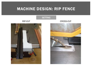
This document provides information about machine anatomy and construction, specifically regarding surface planers, thicknessers, and rip/panel saws. It discusses the parts, design, functions, processes, safety, use, and maintenance of these machines. The sections cover topics like cutter block design, knife geometry, chip formation, risk assessment, and blade configurations. The goal is to educate students about the components and operation of various woodworking machinery.
Unit -1-Theory of Metal Cutting
Manufacturing Technology is much more essential subjects for Mechanical Engineering According that i am prepare study material for Manufacturing Technology-2 UNIT wise ......1 st unit covered more then enough for this materials get wide knowledge from Manufacturing Division.....
All The Best My Dear Hearts
Remaining Units i will update soon ....
Thank you ....
By: Prof.S.Sathishkumar
The notes offer advice regarding the Irish Post-Primary Junior Certificate Technical Graphics examination. These notes are intended for study purposes only. Not all of the syllabus areas are represented in these notes.
International Journal of Engineering Research and Applications (IJERA) aims to cover the latest outstanding developments in the field of all Engineering Technologies & science.
International Journal of Engineering Research and Applications (IJERA) is a team of researchers not publication services or private publications running the journals for monetary benefits, we are association of scientists and academia who focus only on supporting authors who want to publish their work. The articles published in our journal can be accessed online, all the articles will be archived for real time access.
Our journal system primarily aims to bring out the research talent and the works done by sciaentists, academia, engineers, practitioners, scholars, post graduate students of engineering and science. This journal aims to cover the scientific research in a broader sense and not publishing a niche area of research facilitating researchers from various verticals to publish their papers. It is also aimed to provide a platform for the researchers to publish in a shorter of time, enabling them to continue further All articles published are freely available to scientific researchers in the Government agencies,educators and the general public. We are taking serious efforts to promote our journal across the globe in various ways, we are sure that our journal will act as a scientific platform for all researchers to publish their works online.
EXPERIMENTAL INVESTIGATION AND DESIGN OPTIMIZATION OF END MILLING PROCESS PAR...IAEME Publication
Monel 400 is a precipitation hard enable, Nickel copper alloy with corrosion resistance. Typical applications for Monel 400 include fasteners, springs, chain, pump, impeller and Valve components due their excellent Mechanical properties. The continuous development of carbide milling cutter and its coating technology are great concern with manufacturing Environment. CBN coating play an important role in milling cutter to produce better surface finish and tool life with minimum cost. In this paper deals investigation of End Milling operation of Monel 400 plates with different process parameters like spindle speed, feed rate and depth of cut and to find optimal machining conditions of minimum surface roughness(Ra), Material removal designed and conducted based on design of Experiments using L9 orthogonal array and Optimized by Taguchi Method.
experimental study of the influence of tool geometry by optimizing helix angl...INFOGAIN PUBLICATION
Tool selection is a critical part during manufacturing process. The tool geometry plays a vital role in the art of machining to produce the part to meet the quality requirements. The tool parameters which play major roles are tool material, tool geometry, size of the tool and coating of the tool. Out of these, selection of right kind of tool geometry plays a major role by reducing cutting forces and induced stresses, energy consumptions and temperature. All this will leads to reduced distortions and the selection of wrong tool geometry results in enhanced tool cost and loss in production. However these tool geometric features are often neglected during machining considerations and procurement of tools. Thus the objective of the study is to analyze the contribution of tool geometry in peripheral milling operation and to find the optimized helix angle to get minimum cutting force (useful in thin wall machining) and thereby ensuring perpendicularity and best surface finish to reduce the chatter vibration and deflection by optimizing the machining parameters such as spindle speed, feed per tooth and side cut. The experiments are conducted on CNC milling machine on aluminium alloy 2014 using solid carbide end mills of 10 mm diameter with various helix angles by making all other geometric features constant. Taguchi method is used for design of experiment. The optimum level of parameters has been identified using Grey relational analysis (GRA) and also the percentage contribution is identified using ANOVA.
Turning plays most important role in Machining and Turning is the form of machining process which uses a single-point cutting tool for material removal,from this slide we can get the importance of turning.
a cutting tool or cutter is any tool that is used to remove material from the work piece by means of shear deformation. Cutting may be accomplished by single-point or multipoint tools. Single-point tools are used in turning, shaping, planing and similar operations, and remove material by means of one cutting edge. Milling and drilling tools are often multipoint tools. Grinding tools are also multipoint tools. Each grain of abrasive functions as a microscopic single-point cutting edge (although of high negative rake angle), and shears a tiny chip
The intention of this report is to briefly, explain some of the machining operations that are involved in the process of TURNING, these are: Cutting Speed, Depth of Cut, Feed Rate and Spindle Speed.
Also demonstrated will be the mathematical calculations involved in the same process, using various equations.
2019 Design & Communication Graphics (D.C.G.) Revision Notes covering the majority of the DCG syllabus through relevant exam solutions. Feel free to use these notes for study purposes only. Encrypted video links will not work through this platform but the notes should be clear enough to assist you in your understanding and comprehension of DCG learning areas. Best of luck to all students doing Irish Leaving Certificate exams this June (2018).
2018 Design & Communication Graphics (D.C.G.) Revision Notes covering the majority of the DCG syllabus through relevant exam solutions. Feel free to use these notes for study purposes only. Encrypted video links will not work through this platform but the notes should be clear enough to assist you in your understanding and comprehension of DCG learning areas. Best of luck to all students doing Irish Leaving Certificate exams this June (2018).
A Sample of Part A, Outputs 1 - 6, of this years DCG 2017/18 Leaving Certificate project. The document is intended for study purposes only. Remember Output 4 is not a hard-copy Output and is therefore not included in the document. The reference bibliography has also been excluded in this case but please ensure you reference sources in your own research.
FREE LEAVING CERTIFICATE 2017 CONSTRUCTION STUDIES QUESTION 1 NOTESJOE LYSTER
The notes are relevant to Higher Level Leaving Certificate Construction Studies Question 1 - Scale section drawing building detail. Feel free to use as you wish. Best of luck.
The Roman Empire A Historical Colossus.pdfkaushalkr1407
The Roman Empire, a vast and enduring power, stands as one of history's most remarkable civilizations, leaving an indelible imprint on the world. It emerged from the Roman Republic, transitioning into an imperial powerhouse under the leadership of Augustus Caesar in 27 BCE. This transformation marked the beginning of an era defined by unprecedented territorial expansion, architectural marvels, and profound cultural influence.
The empire's roots lie in the city of Rome, founded, according to legend, by Romulus in 753 BCE. Over centuries, Rome evolved from a small settlement to a formidable republic, characterized by a complex political system with elected officials and checks on power. However, internal strife, class conflicts, and military ambitions paved the way for the end of the Republic. Julius Caesar’s dictatorship and subsequent assassination in 44 BCE created a power vacuum, leading to a civil war. Octavian, later Augustus, emerged victorious, heralding the Roman Empire’s birth.
Under Augustus, the empire experienced the Pax Romana, a 200-year period of relative peace and stability. Augustus reformed the military, established efficient administrative systems, and initiated grand construction projects. The empire's borders expanded, encompassing territories from Britain to Egypt and from Spain to the Euphrates. Roman legions, renowned for their discipline and engineering prowess, secured and maintained these vast territories, building roads, fortifications, and cities that facilitated control and integration.
The Roman Empire’s society was hierarchical, with a rigid class system. At the top were the patricians, wealthy elites who held significant political power. Below them were the plebeians, free citizens with limited political influence, and the vast numbers of slaves who formed the backbone of the economy. The family unit was central, governed by the paterfamilias, the male head who held absolute authority.
Culturally, the Romans were eclectic, absorbing and adapting elements from the civilizations they encountered, particularly the Greeks. Roman art, literature, and philosophy reflected this synthesis, creating a rich cultural tapestry. Latin, the Roman language, became the lingua franca of the Western world, influencing numerous modern languages.
Roman architecture and engineering achievements were monumental. They perfected the arch, vault, and dome, constructing enduring structures like the Colosseum, Pantheon, and aqueducts. These engineering marvels not only showcased Roman ingenuity but also served practical purposes, from public entertainment to water supply.
Embracing GenAI - A Strategic ImperativePeter Windle
Artificial Intelligence (AI) technologies such as Generative AI, Image Generators and Large Language Models have had a dramatic impact on teaching, learning and assessment over the past 18 months. The most immediate threat AI posed was to Academic Integrity with Higher Education Institutes (HEIs) focusing their efforts on combating the use of GenAI in assessment. Guidelines were developed for staff and students, policies put in place too. Innovative educators have forged paths in the use of Generative AI for teaching, learning and assessments leading to pockets of transformation springing up across HEIs, often with little or no top-down guidance, support or direction.
This Gasta posits a strategic approach to integrating AI into HEIs to prepare staff, students and the curriculum for an evolving world and workplace. We will highlight the advantages of working with these technologies beyond the realm of teaching, learning and assessment by considering prompt engineering skills, industry impact, curriculum changes, and the need for staff upskilling. In contrast, not engaging strategically with Generative AI poses risks, including falling behind peers, missed opportunities and failing to ensure our graduates remain employable. The rapid evolution of AI technologies necessitates a proactive and strategic approach if we are to remain relevant.
June 3, 2024 Anti-Semitism Letter Sent to MIT President Kornbluth and MIT Cor...Levi Shapiro
Letter from the Congress of the United States regarding Anti-Semitism sent June 3rd to MIT President Sally Kornbluth, MIT Corp Chair, Mark Gorenberg
Dear Dr. Kornbluth and Mr. Gorenberg,
The US House of Representatives is deeply concerned by ongoing and pervasive acts of antisemitic
harassment and intimidation at the Massachusetts Institute of Technology (MIT). Failing to act decisively to ensure a safe learning environment for all students would be a grave dereliction of your responsibilities as President of MIT and Chair of the MIT Corporation.
This Congress will not stand idly by and allow an environment hostile to Jewish students to persist. The House believes that your institution is in violation of Title VI of the Civil Rights Act, and the inability or
unwillingness to rectify this violation through action requires accountability.
Postsecondary education is a unique opportunity for students to learn and have their ideas and beliefs challenged. However, universities receiving hundreds of millions of federal funds annually have denied
students that opportunity and have been hijacked to become venues for the promotion of terrorism, antisemitic harassment and intimidation, unlawful encampments, and in some cases, assaults and riots.
The House of Representatives will not countenance the use of federal funds to indoctrinate students into hateful, antisemitic, anti-American supporters of terrorism. Investigations into campus antisemitism by the Committee on Education and the Workforce and the Committee on Ways and Means have been expanded into a Congress-wide probe across all relevant jurisdictions to address this national crisis. The undersigned Committees will conduct oversight into the use of federal funds at MIT and its learning environment under authorities granted to each Committee.
• The Committee on Education and the Workforce has been investigating your institution since December 7, 2023. The Committee has broad jurisdiction over postsecondary education, including its compliance with Title VI of the Civil Rights Act, campus safety concerns over disruptions to the learning environment, and the awarding of federal student aid under the Higher Education Act.
• The Committee on Oversight and Accountability is investigating the sources of funding and other support flowing to groups espousing pro-Hamas propaganda and engaged in antisemitic harassment and intimidation of students. The Committee on Oversight and Accountability is the principal oversight committee of the US House of Representatives and has broad authority to investigate “any matter” at “any time” under House Rule X.
• The Committee on Ways and Means has been investigating several universities since November 15, 2023, when the Committee held a hearing entitled From Ivory Towers to Dark Corners: Investigating the Nexus Between Antisemitism, Tax-Exempt Universities, and Terror Financing. The Committee followed the hearing with letters to those institutions on January 10, 202
Honest Reviews of Tim Han LMA Course Program.pptxtimhan337
Personal development courses are widely available today, with each one promising life-changing outcomes. Tim Han’s Life Mastery Achievers (LMA) Course has drawn a lot of interest. In addition to offering my frank assessment of Success Insider’s LMA Course, this piece examines the course’s effects via a variety of Tim Han LMA course reviews and Success Insider comments.
Instructions for Submissions thorugh G- Classroom.pptxJheel Barad
This presentation provides a briefing on how to upload submissions and documents in Google Classroom. It was prepared as part of an orientation for new Sainik School in-service teacher trainees. As a training officer, my goal is to ensure that you are comfortable and proficient with this essential tool for managing assignments and fostering student engagement.
How to Make a Field invisible in Odoo 17Celine George
It is possible to hide or invisible some fields in odoo. Commonly using “invisible” attribute in the field definition to invisible the fields. This slide will show how to make a field invisible in odoo 17.
The French Revolution, which began in 1789, was a period of radical social and political upheaval in France. It marked the decline of absolute monarchies, the rise of secular and democratic republics, and the eventual rise of Napoleon Bonaparte. This revolutionary period is crucial in understanding the transition from feudalism to modernity in Europe.
For more information, visit-www.vavaclasses.com
1. WT5912
TECHNOLOGY EDUCATION &
WORKSHOP PRACTICE 2:
MATERIALS AND CONSTRUCTION
UNIT 2 – WEEK 3 Machine Anatomy
and Construction
Course Involved: Graduate Diploma in Technology Education
Studies Detail
University of Limerick
Department of Design & Manufacturing Technology
Lecturer/Teacher: Mr. Joseph Lyster
Academic Year 2012: Spring Semester
Technical Support: Mr. Joe Murray & Mr. Richie Hennessy
Notes Prepared by: Mr. Joseph Lyster
Available on www.slideshare.net/WT4603
UNIVERSITY of LIMERICK
OLLSCOIL LUIMNIGH
3. SURFACE PLANER
When planing wooden material a number of factors
combine to generate the flat surface.
Number of cutting knives in the block
Speed of the revolving block
Feed speed of the material
Knife cutter design
Chip breaking aids
Nature and species of the material
5. MACHINE DESIGN: CIRCULAR CUTTER BLOCK
• Reduced noise levels
• Better balance
• Safer clamping mechanism
• Can run head at higher speeds (RPM)
• Can produce better finish
• Easier and quicker maintenance
Department of Manufacturing & Operations Engineering
6. MACHINE DESIGN: CIRCULAR CUTTER BLOCK
KNIFE CLAMPING MECHANISM
Department of Manufacturing & Operations Engineering
7. MACHINE DESIGN: CIRCULAR CUTTER BLOCK
CUTTER PROJECTION
Use of a limiter to achieve limited cutter projection
Department of Manufacturing & Operations Engineering
8. MACHINE DESIGN: CIRCULAR CUTTER BLOCK
CUTTER PROJECTION
The cutter projection and the shape of the block face cause
the severed chip to bend back causing a crack across its
width
This makes long grain riving less likely
(Chip breaker not shown)
9. MACHINE DESIGN: PLANER KNIVES
Planer Knives
Impor tant factor s when selecting a planer knife
Suitability for cutter block
Material being processed
Finish required
Volume being machined
Clamping and setting mechanisms
Planers can have 2,3,4,6……. Cutter knives.
Most smaller machines such as those found in schools will have 2,3
or 4 knives.
10. MACHINE DESIGN: PLANER KNIVES
Knives can be made from Chrome Vanadium steel
alloy.
This is suitable for machining softwoods and non
abrasive hardwoods.
However with advances in machining technology
better materials have been developed to machine
wood and wood composites.
Chrome Vanadium knives dull quickly on harder
more dense material.
This requires more sharpening, setting up and
leads to a lot of time wastage.
11. MACHINE DESIGN: PLANER KNIVES
High Speed Steel (HSS) is a cobalt steel alloy with a small
percentage of Tungsten added.
It is more suitable for machining all types of wood than the
chrome steel compounds.
Abrasive stock should be machined using solid or tipped
cutters.
Tungsten Carbide (TC) is the best tool compound for
machining manufactured boards.
For general work HSS cutters are preferred to TC
Cutters can be re-sharpened easily.
A keener edge can be achieved on HSS giving a better finish
12. MACHINE DESIGN: PLANER KNIVES
The reason for this is that steel compounds are smelted and
shaped by rolling and forging while the metal is close to
melting point.
The molecules of the compound flow and align themselves in
response to this pressure giving the material maximum strength
and edge holding capabilities
Department of Manufacturing & Operations Engineering
13. MACHINE DESIGN: PLANER KNIVES
Tungsten carbide is a sintered compound. The fine grain
powder from which the cutter will eventually will be made is
compressed into a mould ( the ‘blank’ un-edged cutter
required) under extremely high temperature (1500 C) and
pressure to form a solid block.
Tungsten does not flow – it retains a granular structure and
will chip rather than deform if abused.
Department of Manufacturing & Operations Engineering
14. MACHINE DESIGN: PLANER KNIVES
Because if its brittle nature TC cutters require a more
obtuse sharpness angle than the HSS cutters (more support
for the cutting edge).
This makes it less satisfactory for cutting softwoods than
HSS knives which can be ground to a more acute cutting
angle.
Department of Manufacturing & Operations Engineering
15. MACHINE DESIGN: PLANER KNIVES
Cutter Cutter
Knife Knife
H SS
TC
Large grinding angle Smaller grinding angle
to support cutting edge produces keen edge
Department of Manufacturing & Operations Engineering
16. MACHINE FUNCTION: KNIFE CUTTER GEOMETRY
Rake or Cutting angle
Angle created between the
face of the cutting knife Cutting
and the centre of the cutter Angle
block
Can have a wide range
Softwoods 27 to 35
Hardwoods 15 to 25
Department of Manufacturing & Operations Engineering
17. MACHINE FUNCTION: KNIFE CUTTER GEOMETRY
Bevel or Lip Angle
Angle formed to give
the cutting edge
Bevel
Minimum of usually Angle
35
Greater for tipped
cutters
Department of Manufacturing & Operations Engineering
18. MACHINE FUNCTION: KNIFE CUTTER GEOMETRY
Clearance Angle
Angle formed between
a line tangential to
cutting circle and the
bevel angle of the
Cutter Circle
knife Diameter
Must be present Clearance
Angle
Has a bearing on the
life of the cutting edge
Usually 10 to 15
Department of Manufacturing & Operations Engineering
19. MACHINE FUNCTION: KNIFE CUTTER GEOMETRY
Peripheral Cutting
Speed
Cutter
Rotation
A constant speed in
the range of 35-45
m/s will give best
results
Increase in speed may Cutter Circle
cause loss of dynamic Diameter
balance due to
vibrations
Poor finish
Increased noise levels
Work Movement Direction
Department of Manufacturing & Operations Engineering
20. MACHINE FUNCTION
PITCH DISTANCE
Combination of a rotary Pitch
cut and a linear feed
will leave the surface of
t
the material with a Work Piece
Fast Feed Rate
series of arcs on it
called Curtate Trochoids Pitch
The pitch and depth of Work Piece
t
these arcs will Slower Feed Rate
determine how smooth
t = Cutter arc depth on
the surface finish will machined surface
be
Department of Manufacturing & Operations Engineering
21. MACHINE FUNCTION
P I T C H D I S TA N C E
2mm to 3mm for non obvious joinery and painted
external work.
1mm to 1.5 mm for internal painted work.
0.5mm to 1mm for hardwood joinery and
furniture.
Department of Manufacturing & Operations Engineering
22. MACHINE FUNCTION
PITCH DISTANCE
The SI unit of time is the second , but the minute is acceptable.
Feed rate on wood working machines is expressed in metres per
minute. (m/min)
The formula for the pitch of the cutter marks is given by:
f
p = -------
nR
where p = pitch of cutter mark
f = fe e d r a te
n = n u m b e r o f e f fe c t i v e c u t te r s
R = r e v o l u t i o n s p e r m i n u te o f b l o c k
Department of Manufacturing & Operations Engineering
23. MACHINE FUNCTION
PITCH DISTANCE
The unit for “p” will be metres (m)
f m/min m min
p = ---- = --------- = ----- x ------ = m
nR 1/min min 1
Department of Manufacturing & Operations Engineering
24. MACHINE FUNCTION
PITCH DISTANCE
Problem 1
Calculate the cutter pitch of a 4 cutter block revolving at 4200
rev/min with a feed speed of 24m/min.
F 24 24
p = ------- = ------------ = --------- = 0.0014m = 1.4mm
nR 4 x 4200 16800
(Internal painted work)
Department of Manufacturing & Operations Engineering
25. MACHINE FUNCTION
PITCH DISTANCE
If a graded surface is specified and the machine has a multi -
speed feed gearbox, the same formula is used but “f” is
expressed in terms of n ,p, and R.
f
p = ------- f = nRp
nR
Department of Manufacturing & Operations Engineering
36. MACHINE PROCESSES: CHIP FORMATION
Chip breaking aid
and pressure bar
prevent riving and
splintering
Department of Manufacturing & Operations Engineering
37. MACHINE MAINTENANCE
Cutter and Machine Maintenance
Involves:
1. Grinding and setting of knives
2. Roller and pressure bar setting
3. Prevention of resin build up on table and rollers.
4. Attention to:
bearing wear
feed complex adjustments
rise and fall table
Department of Manufacturing & Operations Engineering
38. MACHINE MAINTENANCE
Grinding
The grinding angle of a cutter can vary between 30 to 35
This is increased to 40 for hardwoods (cutting edge lasts
longer)
Overheating
May produce micro cracks in the cutting edge which can
run into gaps when the cutter is used.
May cause the cutter to bow due to expansion.
Department of Manufacturing & Operations Engineering
39. MACHINE MAINTENANCE
Overheating can be avoided
By taking light cuts.
By ensuring that the grind wheel is ‘dressed’ when required to
ensure that the face is open and not glazed when grinding the
knives.
By using a ‘soft’ grinding wheel on HSS cutters – the soft
structure of the wheel allows its grains to break away as soon
as they are blunt revealing sharper ones.
By wet grinding – this is the grinding of cutters while partially
submerged in a mixture of water and soluble oil. The water is a
coolant to prevent frictional heat developing and to disperse it
should it occur. The oil prevents rust in the cutters and it provides
a degree of cutting lubrication .
Department of Manufacturing & Operations Engineering
40. MACHINE MAINTENANCE
Setting Cutters in Block
Before setting the following points should be checked.
The out feed table and cutter block must be clean and free
from dust resin.
Method of adjusting cutters.
Area where setting device is used from should be free from
resin and damage.
Straightness of cutters.
Cutters correctly balanced both in weight and end for end.
Department of Manufacturing & Operations Engineering
41. MACHINE MAINTENANCE
Setting of knives will greatly depend on the type of
cutter block
Knife cutter projection
Chip breaker
Knife parallel to table
All knives in the same peripheral cutting circle
(Refer to machine manual for setting)
Department of Manufacturing & Operations Engineering
42. MACHINE MAINTENANCE
Setting devices
There are a number of cutter setting devices.
This device and procedure will often be supplied with the machine.
They can be loosely placed into the following four categories:
1. Bridge device
2. Precision cutter setter device
3. Pin locater device
4. Wooden straight edge device
5. Cutter s require accurate setting in the block because if the knives
are not revolving in the same cutting circle a poor finish will be
produced.
Department of Manufacturing & Operations Engineering
48. CIRCULAR SAWING MACHINES
NOTE Circular sawing machines are high risk woodworking
machinery
Pupils should not be permitted to use this machine.
BS 4163:2000
The machine should be included in a planned maintenance
program that should include electrical safety tests.
Read Circular Sawing Machines (Week 6 Notes)
51. MACHINE DESIGN: SAW BLADE
TOOTH CONFIGURATION
The shape of the saw blade tooth and the way the
teeth are grouped also affect the way the blade
cuts. The configuration of the teeth on a saw blade
has a lot to do with whether the blade will work
best for ripping, crosscutting, or laminates.
Of course, no matter which tooth design you're
looking at, more teeth will give you a smoother cut
than fewer teeth.
53. MACHINE DESIGN: SAW BLADE
TOOTH CONFIGURATION
A cross cut blade will do the
A ripping blade will have a Flat best job with an Alternating
Top Grind (FTG) for fast cutting Top Bevel (ATB), cutting across
with the grain. the grain like a knife and
producing a ver y smooth cut.
A blade with Triple Chip Grind (TCG) is
good for all-purpose cutting and also
gives you a ver y clean cut.
TCG blades are also good for cutting non -
ferrous metals and plastics.
54. MACHINE DESIGN: SAW BLADE
TOOTH CONFIGURATION
In general, blades with more teeth yield a smoother cut, and
blades with fewer teeth move material faster.
A 250mm blade designed for ripping wood can have as few
as 24 teeth, and is designed to quickly move material along
the length of the grain.
A rip blade isn't designed to yield a mirror -smooth cut, but a
good rip blade will move through wood with little ef fort and
leave a clean cut with a minimum of scoring.
55. MACHINE DESIGN: SAW BLADE
TOOTH CONFIGURATION
A crosscut blade is designed to give a smooth cut
across the grain of the wood, without any
splintering or tearing of the material.
A crosscut blade will usually have from 60 to 80
teeth. More teeth mean that each tooth has to cut
less material.
The result is a cleaner cut on edges and a smoother
cut surface. With a top-quality crosscut blade, the
cut surface will appear polished.
56. MACHINE DESIGN: SAW BLADE
HOOK ANGLE
In both Rip and Cross -cutting saws the Hook angle determines
The feel of the cut
The quality of the finish
The power consumed
The approach angle of the saw varies according to the relative
position of the tooth in the downward cutting arc.
This angle alter s from the top plane of the timber where the tooth
top makes fir st contact to compress the timber before the tooth
point engages, to a plane where the tooth angle and the timber face
are parallel.
58. MACHINE DESIGN: SAW BLADE
HOOK ANGLE
The amount of Hook determines the degree to which
the tooth will drive into the timber during the cut.
The effect is of the timber being drawn forward.
The greater the hook angle the greater this tendency.
Too great of a hook angle will result in
Harsh cut
Tearing
Poor finish
Less rigid tooth
Vibration.
59. MACHINE DESIGN: SAW BLADE
HOOK ANGLE
A blade with high positive hook angle (+20 ) will have a ver y
aggressive cut and a fast feed rate.
A low or negative hook angle will slow the feed rate and will also
inhibit the blade's tendency to "climb" the material being cut.
A blade for ripping wood on a table saw will generally have a high
hook angle, where an aggressive, fast cut is usually what you
want.
Radial arms saws and sliding compound mitre saws, on the other
hand, require a blade with a ver y low or negative hook angle, to
inhibit overly fast feed rate, binding, and the blade's tendency to
tr y to "climb" the material
60. MACHINE DESIGN: SAW BLADE
HOOK ANGLE
On most saw blades, the tooth faces are tipped either toward
or away from the direction of rotation of the blade, rather than
being perfectly in line with the centre of the blade.
Hook angle is the angle formed between the tooth face and a
line drawn from the centre of the blade across the tip of the
tooth.
On a blade with a positive hook angle, the teeth are tipped
toward the direction of the blade's rotation.
A negative hook angle means that teeth tip away from the
direction of rotation, and a zero degree hook angle means that
the teeth are in line with the centre of the blade.
63. MACHINE DESIGN: SAW BLADE
GULLET
The gullet is the space cut away from the blade plate in
front of each tooth to allow for chip removal.
In a ripping operation, the feed rate is faster than in
crosscutting and the chip size is bigger, so the gullet
needs to be deep enough to make room for the large
amount of material it has to handle.
In a crosscutting blade the chips are smaller and fewer
per tooth, so the gullet is much smaller. The gullets on
some crosscutting blades are purposely sized small to
inhibit a too-fast feed rate, which can be a problem,
especially on radial arm and sliding mitre saws.
65. MACHINE DESIGN: SAW BLADE
GULLET
The gullets of a combination blade are
designed to handle both ripping and
crosscutting. The large gullets between the
groups of teeth help clear out the larger
amounts of material generated in ripping.
The smaller gullets between the grouped teeth
inhibit a too-fast feed rate in crosscutting
67. MACHINE DESIGN: SAW BLADE
CLEARANCE
Work clearance must be provided.
The saw tooth provides this clearance.
The „Kerf‟ produced by the teeth must be wider than the
supporting saw plate.
Steel saws had the kerf formed by bending or „setting‟
alternate teeth laterally.
With tipped saws the tips are wider than the saw plate and
thus create the clearance.
Clearance or relief bevels are ground on the sides and the
top of each tooth.
68. MACHINE DESIGN: SAW BLADE
PLATE TENSION
A flat disc will remain flat and true if turned at a slow
speed.
When variable stresses are created on this disc due to:
Braking effect of sawing
Heating effect of friction
Outward pull of centrifugal force
the outer rim area of the disc will expand.
If the whole area of the disc can expand at the same
rate the disc will remain flat and true.
This does not happen with a saw blade.
The central region of the blade is clamped between the
collars and does not expand.
69. MACHINE DESIGN: SAW BLADE
PLATE TENSION
Only the teeth of the saw blade should make contact with the work
and a por tion of the energy expended in cutting will unavoidably
be conver ted to heat.
The peripher y of the blade will therefore tend to warm up more
quickly than the main plate body.
This will cause the peripher y of the blade to expand.
If this is not taken into account the blade will distor t.
To prevent this saw blades are „tensioned‟ during the
manufacturing stage.
Rim speed will determine the amount of tension required in a
par ticular saw blade.
Thinner saw blades require greater tension.
Faster saws require more tension.
70. MACHINE DESIGN: SAW BLADE
PLATE TENSION
Traditionally this was done by highly skilled labour but modern
saw manufacturers use machine operated roller s to achieve a
faster more uniform result.
This within limits allows the plate to expand uniformly in uneven
temperature gradients.
A blade which has lost its tension will be seen to be throwing from
side to side.
This is most noticeable as the blade slows down af ter the machine
is switched of f.
If this is the case the blade should be removed and sent for
ser vicing.
This can be reduced by cooling the blade tip while in operation by
packing.
71. MACHINE DESIGN: SAW BLADE
PLATE TENSION
TC tipped blades have an extremely long life and to assist
the tension factor, slots are incorporated around the edge of
the blade.
These allow a degree of individual expansion between
segments on the plate edge.
They also break up harmonic frequencies, which build up
during the sawing process.
81. MACHINE DESIGN: BLADE GUARD
TOP BLADE GUARD
Covers the top edge of the saw blade.
Deflects waste.
Prevents accidental contact with the uppermost teeth of the
blade.
It can also limit the ef fects of material rejection.