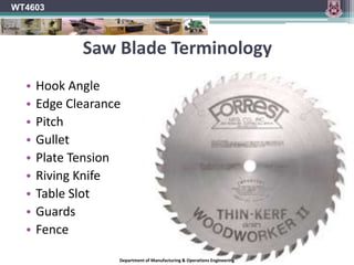
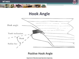
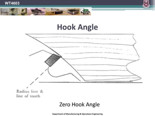
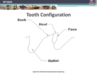
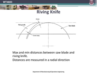
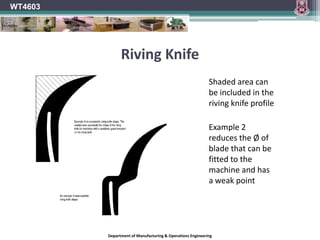
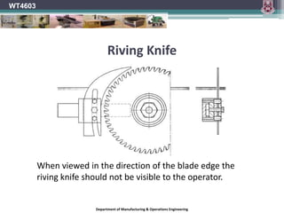
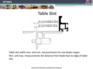
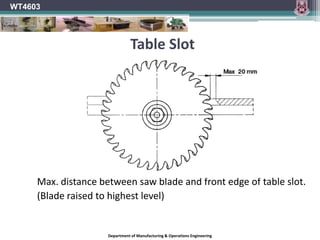
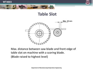
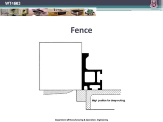
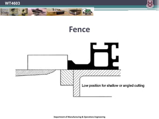
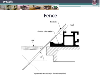
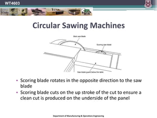
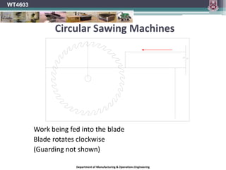
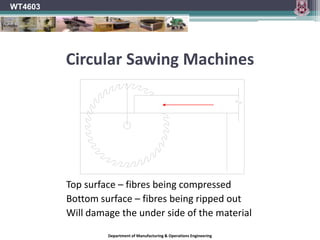
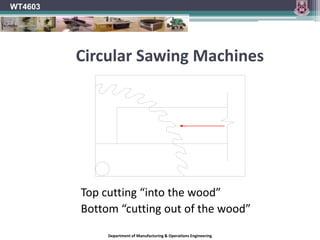
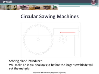
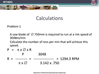
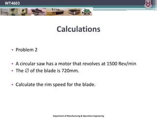
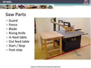
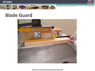
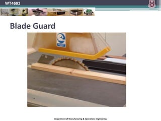
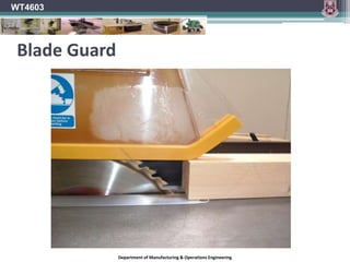
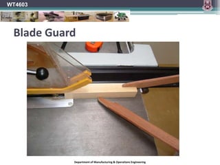
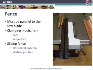
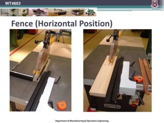
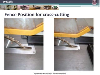
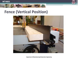
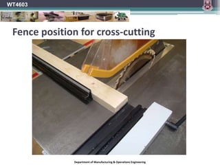
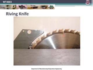
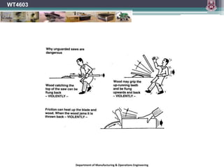
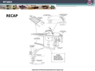
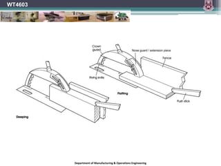
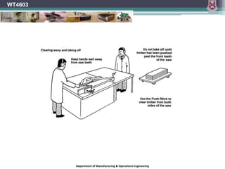
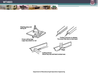
WT4603Wood Processing Safety & PracticeLecture Unit 5 (Week 6) Postponed until Week 7Circular Saws
 Lecturer: Mr. Joseph Lyster
joseph.lyster@ul.ie
 Notes prepared by: Mr. Donal Canty, Mr. Des Kelly and Mr. Joseph Lyster
 Notes available on www.slideshare.net/WT4603Circular Sawing Machine	NOTE Circular sawing machines are high risk woodworking machinery	Pupils should not be permitted to use this machine.	BS 4163:2000 The machine should be included in a planned maintenance program that should include electrical safety tests.Read Circular Sawing Machines (Week 6 Notes)WT4603Department of Manufacturing & Operations Engineering
WT4603HazardsOperators should be aware of the following hazards.The work piece can become jammed in the circular sawing machine or can kick back.Hands or fingers can come into contact with the blade.Wood dust can be inhaled.Noise can cause permanent hearing damage.Inadvertent starting of the machine can present a hazard.Department of Manufacturing & Operations Engineering
Risk control measuresIt is essential that the machine be provided with:A means of electrical isolation using a fused switch-disconnector on or adjacent to the machine, and that it is controlled by a starter incorporating overload protection and no-volt releaseA conveniently positioned, mushroom-headed stop button or suitable other control device that can quickly stop the machine in an emergencyWT4603Department of Manufacturing & Operations Engineering
Risk control measuresFixed guards (removable only with the use of a tool), or alternatively interlocked guards that encloses the drive mechanisms.It should be possible to lock the machine to off when not in use, if a locking device is not incorporated in the machine.There should be sufficient space around the saw bench so that the timber can be handled safely. The floor of the work area should be level. The floor surface should be kept free from loose material and should be non-slippery.WT4603Department of Manufacturing & Operations Engineering
WT4603Saw Blade TerminologyHook AngleEdge ClearancePitchGulletPlate TensionRiving KnifeTable SlotGuardsFenceDepartment of Manufacturing & Operations Engineering
WT4603Hook AngleDepartment of Manufacturing & Operations Engineering
WT4603Hook AngleOn most saw blades, the tooth faces are tipped either toward or away from the direction of rotation of the blade, rather than being perfectly in line with the centre of the blade. Hook angle is the angle formed between the tooth face and a line drawn from the centre of the blade across the tip of the tooth. On a blade with a positive hook angle, the teeth are tipped toward the direction of the blade's rotation. A negative hook angle means that teeth tip away from the direction of rotation, and a zero degree hook angle means that the teeth are in line with the centre of the blade.Department of Manufacturing & Operations Engineering
WT4603Hook AnglePositive Hook AngleDepartment of Manufacturing & Operations Engineering
WT4603Hook AngleZero Hook AngleDepartment of Manufacturing & Operations Engineering
Hook AngleWT4603	In both Rip and Cross-cutting saws the Hook angle determinesThe feel of the cutThe quality of the finishThe power consumedDepartment of Manufacturing & Operations Engineering
Hook AngleWT4603The approach angle of the saw varies according to the relative position of the tooth in the downward cutting arc.This angle alters from the top plane of the timber where the tooth top makes first contact to compress the timber before the tooth point engages, to a plane where the tooth angle and the timber face are parallel.Department of Manufacturing & Operations Engineering
WT4603Hook AngleThe amount of Hook determines the degree to which the tooth will drive into the timber during the cut.The effect is of the timber being drawn forward.The greater the hook angle the greater this tendency.	Too great of a hook angle will result inHarsh cutTearingPoor finishLess rigid toothVibration.Department of Manufacturing & Operations Engineering
Hook AngleA blade with high positive hook angle (+20°) will have a very aggressive cut and a fast feed rate.  A low or negative hook angle will slow the feed rate and will also inhibit the blade's tendency to "climb" the material being cut.  A blade for ripping wood on a table saw will generally have a high hook angle, where an aggressive, fast cut is usually what you want.  Radial arms saws and sliding compound mitre saws, on the other hand, require a blade with a very low or negative hook angle, to inhibit overly fast feed rate, binding, and the blade's tendency to try to "climb" the materialWT4603Department of Manufacturing & Operations Engineering
Tooth ConfigurationThe shape of the saw blade tooth and the way the teeth are grouped also affect the way the blade cuts.  The configuration of the teeth on a saw blade has a lot to do with whether the blade will work best for ripping, crosscutting, or laminates. Of course, no matter which tooth design you're looking at, more teeth will give you a smoother cut than fewer teeth.WT4603Department of Manufacturing & Operations Engineering
WT4603Tooth Configuration	A ripping blade will have a Flat Top Grind (FTG) for fast cutting with the grain.Department of Manufacturing & Operations Engineering
WT4603Tooth Configuration	A cross cut blade will do the best job with an Alternating Top Bevel (ATB), cutting across the grain like a knife and producing a very smooth cut.Department of Manufacturing & Operations Engineering
WT4603Tooth Configuration	A blade with Triple Chip Grind (TCG) is good for all-purpose cutting and also gives you a very clean cut. 	TCG blades are also good for cutting non-ferrous metals and plastics.Department of Manufacturing & Operations Engineering
WT4603Tooth ConfigurationDepartment of Manufacturing & Operations Engineering
Tooth ConfigurationIn general, blades with more teeth yield a smoother cut, and blades with fewer teeth move material faster.A 250mm blade designed for ripping wood can have as few as 24 teeth, and is designed to quickly move material along the length of the grain. A rip blade isn't designed to yield a mirror-smooth cut, but a good rip blade will move through wood with little effort and leave a clean cut with a minimum of scoring.WT4603Department of Manufacturing & Operations Engineering
Tooth ConfigurationWT4603A crosscut blade is designed to give a smooth cut across the grain of the wood, without any splintering or tearing of the material.A crosscut blade will usually have from 60 to 80 teeth. More teeth mean that each tooth has to cut less material. The result is a cleaner cut on edges and a smoother cut surface.  With a top-quality crosscut blade, the cut surface will appear polished.Department of Manufacturing & Operations Engineering
WT4603GulletThe gullet is the space cut away from the blade plate in front of each tooth to allow for chip removal.  	In a ripping operation, the feed rate is faster than in crosscutting and the chip size is bigger, so the gullet needs to be deep enough to make room for the large amount of material it has to handle. 	In a crosscutting blade the chips are smaller and fewer per tooth, so the gullet is much smaller.  The gullets on some crosscutting blades are purposely sized small to inhibit a too-fast feed rate, which can be a problem, especially on radial arm and sliding mitre saws. Department of Manufacturing & Operations Engineering
GulletWT4603The gullets of a combination blade are designed to handle both ripping and crosscutting. The large gullets between the groups of teeth help clear out the larger amounts of material generated in ripping. The  smaller gullets between the grouped teeth inhibit a too-fast feed rate in crosscuttingDepartment of Manufacturing & Operations Engineering
Riving KnifeWT4603	The riving knife must be tapered at its leading edge	Note :	The thickness of the riving knife is to be approx. 10% thicker than the plate of the saw blade but must be less than the saw kerf “B”.Department of Manufacturing & Operations Engineering
WT4603Riving Knife	Riving knife should not be set higher than the highest point of the saw bladeDepartment of Manufacturing & Operations Engineering
WT4603Riving Knife	Max and min distances between saw blade and riving knife.	Distances are measured in a radial directionDepartment of Manufacturing & Operations Engineering
WT4603Riving Knife	Shaded area can be included in the riving knife profile	Example 2 reduces the Ø of blade that can be fitted to the machine and has a weak pointDepartment of Manufacturing & Operations Engineering
WT4603Riving Knife	When viewed in the direction of the blade edge the riving knife should not be visible to the operator.Department of Manufacturing & Operations Engineering
WT4603Table Slot	Table slot width max. and min. measurements for saw blade ranges.	Min. and max. measurements for distance from blade face to edge of table slot. Department of Manufacturing & Operations Engineering
WT4603Table Slot	Max. distance between saw blade and front edge of table slot.	(Blade raised to highest level)Department of Manufacturing & Operations Engineering
WT4603Table Slot	Max. distance between saw blade and front edge of table slot on machine with a scoring blade.	(Blade raised to highest level)Department of Manufacturing & Operations Engineering
ClearanceWT4603	The supporting body of the cutting tip is ‘relieved’ or ground back (X) so that only the cutting edge itself makes work contact.	For any machine cutting tool to work efficiently, only the cutting edge of the tool should be making contact with the work.Department of Manufacturing & Operations Engineering
ClearanceWork clearance must be provided.The saw tooth provides this clearance.The ‘Kerf’ produced by the teeth must be wider than the supporting saw plate.Steel saws had the kerf formed by bending or ‘setting’ alternate teeth laterally.With tipped saws the tips are wider than the saw plate and thus create the clearance.Clearance or relief bevels are ground on the sides and the top of each tooth.WT4603Department of Manufacturing & Operations Engineering
Plate TensionA flat disc will remain flat and true if turned at a slow speed.When variable stresses are created on this disc due to:Braking effect of sawingHeating effect of frictionOutward pull of centrifugal forcethe outer rim area of the disc will expand.If the whole area of the disc can expand at the same rate the disc will remain flat and true.This does not happen with a saw blade.The central region of the blade is clamped between the collars and does not expand.WT4603Department of Manufacturing & Operations Engineering
Plate TensionOnly the teeth of the saw blade should make contact with the work and a portion of the energy expended in cutting will unavoidably be converted to heat.The periphery of the blade will therefore tend to warm up more quickly than the main plate body.This will cause the periphery of the blade to expand.If this is not taken into account the blade will distort.To prevent this saw blades are ‘tensioned’ during the manufacturing stage.Rim speed will determine the amount of tension required in a particular saw blade.Thinner saw blades require greater tension.Faster saws require more tension.WT4603Department of Manufacturing & Operations Engineering
Plate TensionTraditionally this was done by highly skilled labour but modern saw manufacturers use machine operated rollers to achieve a faster more uniform result.This within limits allows the plate to expand uniformly in uneven temperature gradients.A blade which has lost its tension will be seen to be throwing from side to side.This is most noticeable as the blade slows down after the machine is switched off.If this is the case the blade should be removed and sent for servicing.This can be reduced by cooling the blade tip while in operation by packing.WT4603Department of Manufacturing & Operations Engineering
Plate TensionTC tipped blades have an extremely long life and to assist the tension factor, slots are incorporated around the edge of the blade.These allow a degree of individual expansion between segments on the plate edge.They also break up harmonic frequencies, which build up during the sawing process.WT4603Department of Manufacturing & Operations Engineering
Top GuardCovers the top edge of the saw blade.Deflects waste.Prevents accidental contact with the uppermost teeth of the blade.It can also limit the effects of material rejection. WT4603Department of Manufacturing & Operations Engineering
WT4603Top GuardDepartment of Manufacturing & Operations Engineering
WT4603Blade GuardBlade guard that completely encloses the blade Department of Manufacturing & Operations Engineering
WT4603Blade GuardGuard not connected to riving knifeGuard has lead in at the frontDust extraction integrated in the guardDepartment of Manufacturing & Operations Engineering
FenceWT4603Department of Manufacturing & Operations Engineering
WT4603FenceDepartment of Manufacturing & Operations Engineering
WT4603Circular Sawing MachinesScoring blade rotates in the opposite direction to the saw bladeScoring blade cuts on the up stroke of the cut to ensure a clean cut is produced on the underside of the panelDepartment of Manufacturing & Operations Engineering
WT4603Circular Sawing Machines	Work being fed into the blade	Blade rotates clockwise	(Guarding not shown)Department of Manufacturing & Operations Engineering
Circular Sawing MachinesWT4603Top surface – fibres being compressedBottom surface – fibres being ripped outWill damage the under side of the materialDepartment of Manufacturing & Operations Engineering
WT4603Circular Sawing MachinesTop cutting “into the wood”Bottom “cutting out of the wood”Department of Manufacturing & Operations Engineering
WT4603Circular Sawing Machines	Scoring blade introduced	Will make an initial shallow cut before the larger saw blade will cut the materialDepartment of Manufacturing & Operations Engineering
WT4603Circular Sawing Machines	In this diagram the scoring blade rotates in the same direction as the saw blade	Is this blade still cutting “out of the wood” on the underside ?Department of Manufacturing & Operations Engineering
WT4603Circular Sawing Machines	Here the scoring blade revolves in an anti clockwise direction. As the material passes this blade the cut produced is “into the wood”Department of Manufacturing & Operations Engineering
WT4603Circular Sawing MachinesThis can create a hazard as the blade is unguarded and tends to pull the material towards the saw blade
Should only be used when crosscutting or ripping sheet material where a clean finished cut is required on both surfaces of the panelDepartment of Manufacturing & Operations Engineering
CalculationsWT4603Saw CalculationsRim Speed (P)   =     x  x Spindle Speed (R)	Where 		P  =  Rim SpeedR  =  Spindle Speed=  Diameter in metresUnits     =    m x 1/min   =  m/minThis speed is expressed in metres per minute   m/minIt is left in this format because spindle speed is expressed in Rev/minDepartment of Manufacturing & Operations Engineering
CalculationsProblem 1	A saw blade of   750mm is required to run at a rim speed of  3048m/min	Calculate the number of revs per min that will achieve this speed.P   =     x  x R		       P		   3048R  =   ----------  =   -----------------   =  1294.3 RPM	   	    x  	     3.142 x .750 	WT4603Department of Manufacturing & Operations Engineering
CalculationsWT4603Problem 2A circular saw has a motor that revolves at 1500 Rev/minThe  of the blade is 720mm.Calculate the rim speed for the blade.Department of Manufacturing & Operations Engineering
WT4603Saw PartsGuardFenceBladeRiving KnifeIn feed tableOut feed tableStart / StopFoot stopDepartment of Manufacturing & Operations Engineering
WT4603Blade GuardDepartment of Manufacturing & Operations Engineering
WT4603FenceMust be parallel to the saw bladeClamping mechanismcam  screw lockSliding fenceHorizontal positionVertical positionDepartment of Manufacturing & Operations Engineering
WT4603Fence (Horizontal Position)Department of Manufacturing & Operations Engineering
WT4603Fence Position for cross-cuttingDepartment of Manufacturing & Operations Engineering
WT4603Fence (Vertical Position)Department of Manufacturing & Operations Engineering
WT4603Fence position for cross-cuttingDepartment of Manufacturing & Operations Engineering
WT4603Incorrect settingDepartment of Manufacturing & Operations Engineering
WT4603Incorrect settingMaterial once cut is positioned between the rotating blade and the fixed fence
When the piece is moved by operator or vibration it will contact the moving blade and get ejected
This will result in possible injury to the operator, damage to the blade and damage to the materialDepartment of Manufacturing & Operations Engineering
WT4603Riving KnifeDepartment of Manufacturing & Operations Engineering
WT4603In feed tableDepartment of Manufacturing & Operations Engineering
WT4603Out feed tableDepartment of Manufacturing & Operations Engineering
WT4603Start / StopDepartment of Manufacturing & Operations Engineering
WT4603Foot StopDepartment of Manufacturing & Operations Engineering
WT4603Department of Manufacturing & Operations Engineering
WT4603RECAPDepartment of Manufacturing & Operations Engineering
WT4603Department of Manufacturing & Operations Engineering

Wt4603 unit5 week6

  • 1.
    WT4603Wood Processing Safety& PracticeLecture Unit 5 (Week 6) Postponed until Week 7Circular Saws
  • 2.
    Lecturer: Mr.Joseph Lyster
  • 3.
  • 4.
    Notes preparedby: Mr. Donal Canty, Mr. Des Kelly and Mr. Joseph Lyster
  • 5.
    Notes availableon www.slideshare.net/WT4603Circular Sawing Machine NOTE Circular sawing machines are high risk woodworking machinery Pupils should not be permitted to use this machine. BS 4163:2000 The machine should be included in a planned maintenance program that should include electrical safety tests.Read Circular Sawing Machines (Week 6 Notes)WT4603Department of Manufacturing & Operations Engineering
  • 6.
    WT4603HazardsOperators should beaware of the following hazards.The work piece can become jammed in the circular sawing machine or can kick back.Hands or fingers can come into contact with the blade.Wood dust can be inhaled.Noise can cause permanent hearing damage.Inadvertent starting of the machine can present a hazard.Department of Manufacturing & Operations Engineering
  • 7.
    Risk control measuresItis essential that the machine be provided with:A means of electrical isolation using a fused switch-disconnector on or adjacent to the machine, and that it is controlled by a starter incorporating overload protection and no-volt releaseA conveniently positioned, mushroom-headed stop button or suitable other control device that can quickly stop the machine in an emergencyWT4603Department of Manufacturing & Operations Engineering
  • 8.
    Risk control measuresFixedguards (removable only with the use of a tool), or alternatively interlocked guards that encloses the drive mechanisms.It should be possible to lock the machine to off when not in use, if a locking device is not incorporated in the machine.There should be sufficient space around the saw bench so that the timber can be handled safely. The floor of the work area should be level. The floor surface should be kept free from loose material and should be non-slippery.WT4603Department of Manufacturing & Operations Engineering
  • 9.
    WT4603Saw Blade TerminologyHookAngleEdge ClearancePitchGulletPlate TensionRiving KnifeTable SlotGuardsFenceDepartment of Manufacturing & Operations Engineering
  • 10.
    WT4603Hook AngleDepartment ofManufacturing & Operations Engineering
  • 11.
    WT4603Hook AngleOn mostsaw blades, the tooth faces are tipped either toward or away from the direction of rotation of the blade, rather than being perfectly in line with the centre of the blade. Hook angle is the angle formed between the tooth face and a line drawn from the centre of the blade across the tip of the tooth. On a blade with a positive hook angle, the teeth are tipped toward the direction of the blade's rotation. A negative hook angle means that teeth tip away from the direction of rotation, and a zero degree hook angle means that the teeth are in line with the centre of the blade.Department of Manufacturing & Operations Engineering
  • 12.
    WT4603Hook AnglePositive HookAngleDepartment of Manufacturing & Operations Engineering
  • 13.
    WT4603Hook AngleZero HookAngleDepartment of Manufacturing & Operations Engineering
  • 14.
    Hook AngleWT4603 In bothRip and Cross-cutting saws the Hook angle determinesThe feel of the cutThe quality of the finishThe power consumedDepartment of Manufacturing & Operations Engineering
  • 15.
    Hook AngleWT4603The approachangle of the saw varies according to the relative position of the tooth in the downward cutting arc.This angle alters from the top plane of the timber where the tooth top makes first contact to compress the timber before the tooth point engages, to a plane where the tooth angle and the timber face are parallel.Department of Manufacturing & Operations Engineering
  • 16.
    WT4603Hook AngleThe amountof Hook determines the degree to which the tooth will drive into the timber during the cut.The effect is of the timber being drawn forward.The greater the hook angle the greater this tendency. Too great of a hook angle will result inHarsh cutTearingPoor finishLess rigid toothVibration.Department of Manufacturing & Operations Engineering
  • 17.
    Hook AngleA bladewith high positive hook angle (+20°) will have a very aggressive cut and a fast feed rate.  A low or negative hook angle will slow the feed rate and will also inhibit the blade's tendency to "climb" the material being cut.  A blade for ripping wood on a table saw will generally have a high hook angle, where an aggressive, fast cut is usually what you want.  Radial arms saws and sliding compound mitre saws, on the other hand, require a blade with a very low or negative hook angle, to inhibit overly fast feed rate, binding, and the blade's tendency to try to "climb" the materialWT4603Department of Manufacturing & Operations Engineering
  • 18.
    Tooth ConfigurationThe shapeof the saw blade tooth and the way the teeth are grouped also affect the way the blade cuts.  The configuration of the teeth on a saw blade has a lot to do with whether the blade will work best for ripping, crosscutting, or laminates. Of course, no matter which tooth design you're looking at, more teeth will give you a smoother cut than fewer teeth.WT4603Department of Manufacturing & Operations Engineering
  • 19.
    WT4603Tooth Configuration A rippingblade will have a Flat Top Grind (FTG) for fast cutting with the grain.Department of Manufacturing & Operations Engineering
  • 20.
    WT4603Tooth Configuration A crosscut blade will do the best job with an Alternating Top Bevel (ATB), cutting across the grain like a knife and producing a very smooth cut.Department of Manufacturing & Operations Engineering
  • 21.
    WT4603Tooth Configuration A bladewith Triple Chip Grind (TCG) is good for all-purpose cutting and also gives you a very clean cut. TCG blades are also good for cutting non-ferrous metals and plastics.Department of Manufacturing & Operations Engineering
  • 22.
    WT4603Tooth ConfigurationDepartment ofManufacturing & Operations Engineering
  • 23.
    Tooth ConfigurationIn general,blades with more teeth yield a smoother cut, and blades with fewer teeth move material faster.A 250mm blade designed for ripping wood can have as few as 24 teeth, and is designed to quickly move material along the length of the grain. A rip blade isn't designed to yield a mirror-smooth cut, but a good rip blade will move through wood with little effort and leave a clean cut with a minimum of scoring.WT4603Department of Manufacturing & Operations Engineering
  • 24.
    Tooth ConfigurationWT4603A crosscutblade is designed to give a smooth cut across the grain of the wood, without any splintering or tearing of the material.A crosscut blade will usually have from 60 to 80 teeth. More teeth mean that each tooth has to cut less material. The result is a cleaner cut on edges and a smoother cut surface.  With a top-quality crosscut blade, the cut surface will appear polished.Department of Manufacturing & Operations Engineering
  • 25.
    WT4603GulletThe gullet isthe space cut away from the blade plate in front of each tooth to allow for chip removal.  In a ripping operation, the feed rate is faster than in crosscutting and the chip size is bigger, so the gullet needs to be deep enough to make room for the large amount of material it has to handle. In a crosscutting blade the chips are smaller and fewer per tooth, so the gullet is much smaller.  The gullets on some crosscutting blades are purposely sized small to inhibit a too-fast feed rate, which can be a problem, especially on radial arm and sliding mitre saws. Department of Manufacturing & Operations Engineering
  • 26.
    GulletWT4603The gullets ofa combination blade are designed to handle both ripping and crosscutting. The large gullets between the groups of teeth help clear out the larger amounts of material generated in ripping. The  smaller gullets between the grouped teeth inhibit a too-fast feed rate in crosscuttingDepartment of Manufacturing & Operations Engineering
  • 27.
    Riving KnifeWT4603 The rivingknife must be tapered at its leading edge Note : The thickness of the riving knife is to be approx. 10% thicker than the plate of the saw blade but must be less than the saw kerf “B”.Department of Manufacturing & Operations Engineering
  • 28.
    WT4603Riving Knife Riving knifeshould not be set higher than the highest point of the saw bladeDepartment of Manufacturing & Operations Engineering
  • 29.
    WT4603Riving Knife Max andmin distances between saw blade and riving knife. Distances are measured in a radial directionDepartment of Manufacturing & Operations Engineering
  • 30.
    WT4603Riving Knife Max andmin distances between saw blade and riving knife. Distances are measured in a radial directionDepartment of Manufacturing & Operations Engineering
  • 31.
    WT4603Riving Knife Shaded areacan be included in the riving knife profile Example 2 reduces the Ø of blade that can be fitted to the machine and has a weak pointDepartment of Manufacturing & Operations Engineering
  • 32.
    WT4603Riving Knife When viewedin the direction of the blade edge the riving knife should not be visible to the operator.Department of Manufacturing & Operations Engineering
  • 33.
    WT4603Table Slot Table slotwidth max. and min. measurements for saw blade ranges. Min. and max. measurements for distance from blade face to edge of table slot. Department of Manufacturing & Operations Engineering
  • 34.
    WT4603Table Slot Max. distancebetween saw blade and front edge of table slot. (Blade raised to highest level)Department of Manufacturing & Operations Engineering
  • 35.
    WT4603Table Slot Max. distancebetween saw blade and front edge of table slot on machine with a scoring blade. (Blade raised to highest level)Department of Manufacturing & Operations Engineering
  • 36.
    ClearanceWT4603 The supporting bodyof the cutting tip is ‘relieved’ or ground back (X) so that only the cutting edge itself makes work contact. For any machine cutting tool to work efficiently, only the cutting edge of the tool should be making contact with the work.Department of Manufacturing & Operations Engineering
  • 37.
    ClearanceWork clearance mustbe provided.The saw tooth provides this clearance.The ‘Kerf’ produced by the teeth must be wider than the supporting saw plate.Steel saws had the kerf formed by bending or ‘setting’ alternate teeth laterally.With tipped saws the tips are wider than the saw plate and thus create the clearance.Clearance or relief bevels are ground on the sides and the top of each tooth.WT4603Department of Manufacturing & Operations Engineering
  • 38.
    Plate TensionA flatdisc will remain flat and true if turned at a slow speed.When variable stresses are created on this disc due to:Braking effect of sawingHeating effect of frictionOutward pull of centrifugal forcethe outer rim area of the disc will expand.If the whole area of the disc can expand at the same rate the disc will remain flat and true.This does not happen with a saw blade.The central region of the blade is clamped between the collars and does not expand.WT4603Department of Manufacturing & Operations Engineering
  • 39.
    Plate TensionOnly theteeth of the saw blade should make contact with the work and a portion of the energy expended in cutting will unavoidably be converted to heat.The periphery of the blade will therefore tend to warm up more quickly than the main plate body.This will cause the periphery of the blade to expand.If this is not taken into account the blade will distort.To prevent this saw blades are ‘tensioned’ during the manufacturing stage.Rim speed will determine the amount of tension required in a particular saw blade.Thinner saw blades require greater tension.Faster saws require more tension.WT4603Department of Manufacturing & Operations Engineering
  • 40.
    Plate TensionTraditionally thiswas done by highly skilled labour but modern saw manufacturers use machine operated rollers to achieve a faster more uniform result.This within limits allows the plate to expand uniformly in uneven temperature gradients.A blade which has lost its tension will be seen to be throwing from side to side.This is most noticeable as the blade slows down after the machine is switched off.If this is the case the blade should be removed and sent for servicing.This can be reduced by cooling the blade tip while in operation by packing.WT4603Department of Manufacturing & Operations Engineering
  • 41.
    Plate TensionTC tippedblades have an extremely long life and to assist the tension factor, slots are incorporated around the edge of the blade.These allow a degree of individual expansion between segments on the plate edge.They also break up harmonic frequencies, which build up during the sawing process.WT4603Department of Manufacturing & Operations Engineering
  • 42.
    Top GuardCovers thetop edge of the saw blade.Deflects waste.Prevents accidental contact with the uppermost teeth of the blade.It can also limit the effects of material rejection. WT4603Department of Manufacturing & Operations Engineering
  • 43.
    WT4603Top GuardDepartment ofManufacturing & Operations Engineering
  • 44.
    WT4603Blade GuardBlade guardthat completely encloses the blade Department of Manufacturing & Operations Engineering
  • 45.
    WT4603Blade GuardGuard notconnected to riving knifeGuard has lead in at the frontDust extraction integrated in the guardDepartment of Manufacturing & Operations Engineering
  • 46.
  • 47.
  • 48.
  • 49.
    WT4603Circular Sawing MachinesScoringblade rotates in the opposite direction to the saw bladeScoring blade cuts on the up stroke of the cut to ensure a clean cut is produced on the underside of the panelDepartment of Manufacturing & Operations Engineering
  • 50.
    WT4603Circular Sawing Machines Workbeing fed into the blade Blade rotates clockwise (Guarding not shown)Department of Manufacturing & Operations Engineering
  • 51.
    Circular Sawing MachinesWT4603Topsurface – fibres being compressedBottom surface – fibres being ripped outWill damage the under side of the materialDepartment of Manufacturing & Operations Engineering
  • 52.
    WT4603Circular Sawing MachinesTopcutting “into the wood”Bottom “cutting out of the wood”Department of Manufacturing & Operations Engineering
  • 53.
    WT4603Circular Sawing Machines Scoringblade introduced Will make an initial shallow cut before the larger saw blade will cut the materialDepartment of Manufacturing & Operations Engineering
  • 54.
    WT4603Circular Sawing Machines Inthis diagram the scoring blade rotates in the same direction as the saw blade Is this blade still cutting “out of the wood” on the underside ?Department of Manufacturing & Operations Engineering
  • 55.
    WT4603Circular Sawing Machines Herethe scoring blade revolves in an anti clockwise direction. As the material passes this blade the cut produced is “into the wood”Department of Manufacturing & Operations Engineering
  • 56.
    WT4603Circular Sawing MachinesThiscan create a hazard as the blade is unguarded and tends to pull the material towards the saw blade
  • 57.
    Should only beused when crosscutting or ripping sheet material where a clean finished cut is required on both surfaces of the panelDepartment of Manufacturing & Operations Engineering
  • 58.
    CalculationsWT4603Saw CalculationsRim Speed(P) =  x  x Spindle Speed (R) Where P = Rim SpeedR = Spindle Speed= Diameter in metresUnits = m x 1/min = m/minThis speed is expressed in metres per minute m/minIt is left in this format because spindle speed is expressed in Rev/minDepartment of Manufacturing & Operations Engineering
  • 59.
    CalculationsProblem 1 A sawblade of  750mm is required to run at a rim speed of 3048m/min Calculate the number of revs per min that will achieve this speed.P =  x  x R P 3048R = ---------- = ----------------- = 1294.3 RPM  x  3.142 x .750 WT4603Department of Manufacturing & Operations Engineering
  • 60.
    CalculationsWT4603Problem 2A circularsaw has a motor that revolves at 1500 Rev/minThe  of the blade is 720mm.Calculate the rim speed for the blade.Department of Manufacturing & Operations Engineering
  • 61.
    WT4603Saw PartsGuardFenceBladeRiving KnifeInfeed tableOut feed tableStart / StopFoot stopDepartment of Manufacturing & Operations Engineering
  • 62.
    WT4603Blade GuardDepartment ofManufacturing & Operations Engineering
  • 63.
    WT4603Blade GuardDepartment ofManufacturing & Operations Engineering
  • 64.
    WT4603Blade GuardDepartment ofManufacturing & Operations Engineering
  • 65.
    WT4603Blade GuardDepartment ofManufacturing & Operations Engineering
  • 66.
    WT4603FenceMust be parallelto the saw bladeClamping mechanismcam screw lockSliding fenceHorizontal positionVertical positionDepartment of Manufacturing & Operations Engineering
  • 67.
    WT4603Fence (Horizontal Position)Departmentof Manufacturing & Operations Engineering
  • 68.
    WT4603Fence Position forcross-cuttingDepartment of Manufacturing & Operations Engineering
  • 69.
    WT4603Fence (Vertical Position)Departmentof Manufacturing & Operations Engineering
  • 70.
    WT4603Fence position forcross-cuttingDepartment of Manufacturing & Operations Engineering
  • 71.
    WT4603Fence position forcross-cuttingDepartment of Manufacturing & Operations Engineering
  • 72.
    WT4603Incorrect settingDepartment ofManufacturing & Operations Engineering
  • 73.
    WT4603Incorrect settingMaterial oncecut is positioned between the rotating blade and the fixed fence
  • 74.
    When the pieceis moved by operator or vibration it will contact the moving blade and get ejected
  • 75.
    This will resultin possible injury to the operator, damage to the blade and damage to the materialDepartment of Manufacturing & Operations Engineering
  • 76.
    WT4603Riving KnifeDepartment ofManufacturing & Operations Engineering
  • 77.
    WT4603In feed tableDepartmentof Manufacturing & Operations Engineering
  • 78.
    WT4603In feed tableDepartmentof Manufacturing & Operations Engineering
  • 79.
    WT4603Out feed tableDepartmentof Manufacturing & Operations Engineering
  • 80.
    WT4603Start / StopDepartmentof Manufacturing & Operations Engineering
  • 81.
    WT4603Foot StopDepartment ofManufacturing & Operations Engineering
  • 82.
    WT4603Department of Manufacturing& Operations Engineering
  • 83.
  • 84.
    WT4603Department of Manufacturing& Operations Engineering
  • 85.
    WT4603Department of Manufacturing& Operations Engineering