2024 TOP 10 most fuel-efficient vehicles according to the US agency
Arc welding manual
1. TRAINING PARTNER-CHAMELI DEVI GROUP OF INSTITUTIONS, INDORE
QP NAME-WELDING TECHNICIAN LAVEL-4
WELDING
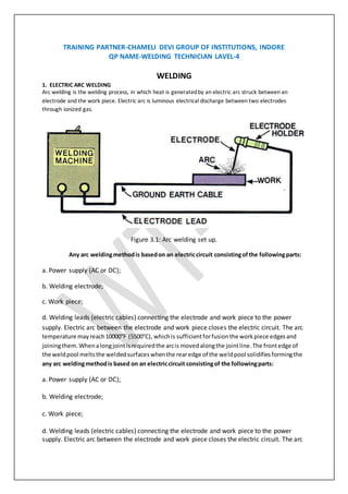
1. ELECTRIC ARC WELDING
Arc welding is the welding process, in which heat is generatedby an electric arc struck between an
electrode and the work piece. Electric arc is luminous electrical discharge between two electrodes
through ionized gas.
Figure 3.1: Arc welding set up.
Any arc weldingmethodis basedon an electriccircuit consistingofthe followingparts:
a. Power supply (AC or DC);
b. Welding electrode;
c. Work piece;
d. Welding leads (electric cables) connecting the electrode and work piece to the power
supply. Electric arc between the electrode and work piece closes the electric circuit. The arc
temperature mayreach10000°F (5500°C), whichis sufficientforfusionthe workpiece edgesand
joiningthem.Whenalongjointisrequiredthe arcis movedalongthe jointline.The frontedge of
the weldpool meltsthe weldedsurfaceswhenthe rearedge of the weldpool solidifiesformingthe
any arc weldingmethodis based on an electriccircuit consistingof the followingparts:
a. Power supply (AC or DC);
b. Welding electrode;
c. Work piece;
d. Welding leads (electric cables) connecting the electrode and work piece to the power
supply. Electric arc between the electrode and work piece closes the electric circuit. The arc
2. temperature may reach 10000°F (5500°C), which is sufficient for fusion the work piece
edges and joining them. When a long joint is required the arc is moved along the joint line.
The front edge of the weld pool melts the welded surfaces when the rear edge of the weld
pool solidifies forming the joint.
Transformers, motor generators and rectifiers’ sets are used as arc welding machines. These
machines supply high electric currents at low voltage and an electrode is used to produce
the necessary arc. The electrode serves as the filler rod and the arc melts the surface so
that, the metals to be joined are actually fixed together.
Sizes of welding machines are rated according to their approximate amperage capacity at
60% duty cycle, such as 150,200,250,300,400,500 and 600 amperes. This amperage is the
rated current output at the working terminal.
Transformers, motor generators and rectifiers’ sets are used as arc welding machines. These
machines supply high electric currents at low voltage and an electrode is used to produce
the necessary arc. The electrode serves as the filler rod and the arc melts the surface so
that, the metals to be joined are actually fixed together.
Sizes of welding machines are rated according to their approximate amperage capacity at
60% duty cycle, such as 150,200,250,300,400,500 and 600 amperes. This amperage is the
rated current output at the working terminal. 3.2.1 Transformers
The transformers type of welding machine produces A.C current and is considered to be the
least expensive. It takes power directly from power supply line and transforms it to the
voltage required for welding. Transformers are available in single phase and three phases in
the market.
1.1 Motor generators
These are D.C generators sets, in which electric motor and alternator are mounted on the
same shaft to produce D.C power as pert the requirement for welding. These are designed
to produce D.C current in either straight or reversed polarity. The polarity selected for
welding depends upon the kind of electrode used and the material to be welded.
1.2. Rectifiers
These are essentially transformers, containing an electrical device which changes A.C into
D.C by virtue of which the operator can use both types of power (A.C or D.C, but only one at
a time).In addition to the welding machine; certain accessories are needed for carrying out
the welding work.
1.3 Welding cables
Two welding cables are required, one from machine to the electrode holder and the other,
from the machine to the ground clamp. Flexible cables are usually preferred because of the
case of using and coiling the cables. Cables are specified by their current carrying capacity,
say 300 A, 400 A, etc.
3. 1.4 Electrodes
Filler rods are used in arc welding are called electrodes. These are made of metallic wire
called core wire, having approximately the same composition as the metal to be welded.
These are coated uniformly with a protective coating called flux. While fluxing an electrode;
about 20mm of length is left at one end for holding it with the electrode holder. It helps in
transmitting full current from electrode holder to the front end of the electrode coating.
Flux acts as an insulator of electricity. Figure.4 shows the various parts of an electrode.
Figure 3.2: Parts of an electrode
In general, electrodes are classified into five main groups; mild steel, carbon steel, special alloy steel, cast
iron and non‐ferrous. The greatest range of arc welding is done with electrodes in the mild steel group.
Various constituents like titanium oxide, potassium oxide, cellulose, iron or manganese, Ferro‐ silicates,
carbonates, gums, clays, asbestos, etc., areused as coatings on electrodes. While welding, the coating or
flux vaporizes and provides a gaseous shield to prevent atmospheric attack.
The sizeof electrode is measured and designated by the diameter of the core wire in SWG and length, apart
from the brand and code names; indicatingthepurpose for which there are most suitable.
Electrodes may be classified on the basis of thickness of thecoated flux. As
1. Dust coated or light coated
2. Semi or medium coated and
3. Heavily coated or shielded
Electrodes are also classified on the basis of materials, as
1. Metallic and
2. Non‐metallic or carbon
Metallic arc electrodes arefurther sub‐divided into
1. Ferrous metal arc electrode (mild steel, low/medium/high carbon steel, castiron,stainlesssteel,etc )
2. Non‐ferrous metal arc electrodes (copper, brass, bronze, aluminum, etc). In case of non‐metallic arc
electrodes, mainly carbon and graphite are used to make the electrodes
1.5 WELDING TOOLS 3.3.1 Electrode holder
The electrode holder is connected to the end of the welding cable and holds the electrode. It should be
light, strong and easy to handle and should not become hot while in operation. Figure shows one type of
electrode holder. The jaws of the holder are insulated, offering protection from electric shock
4. Figure 3.3: Electrode holder Figure 3.4: Ground clamp
1.6 Ground clamp
It is connected to the end of the ground cable and is clamped to the work or welding table to complete
the electric circuit. It should be strong and durable and give a low resistance connection.
1.7 Wire brush and chipping hammer
A wire brush is used for cleaning and preparing the work for welding. A chipping hammer is used for
removing slag formation on welds. One end of the head is sharpened like a cold chisel and the other, to a
blunt, round point. It is generally made of tool steel. Molten metal dispersed around the welding heads,
in the form of small drops, is known as spatter.
Figure 3.5: Wire brush Figure 3.6: Chippinghammer
1.8 Welding table and cabin
It is made of steel plate and pipes. It is used for positioning the parts to be welded properly. Welding
cabin is made‐up by any suitable thermal resistance material, which can isolate the surrounding by the
heat and light emitted during the welding process. A suitable draught should also be provided for
exhausting the gas produced during welding.
1.9 Face shield
A face shield is used to protect the eyes and face from the rays of the arc and from spatter or flying
particles of hot metal. It is available either in hand or helmet type. The hand type is convenient to use
wherever the work can be done with one hand. The helmet type though not comfortable to wear, leaves
both hands free for the work.
Shields are made of light weight non‐reflecting fiber and fitted with dark glasses to filter out the harmful
rays of the arc. In some designs, a cover glass is fitted in front of the dark lens to protect it from spatter
1.9 Hand gloves
These areused to protect the hands from electric shocks and hot spatters
5. Figure 3.7: Hand gloves Figure 3.8: Face shield
2. TECHNIQUES OF WELDING
2.1 Preparationof work
Before welding,the workpiecesmustbe thoroughlycleanedof rust,scale andotherforeign
material.The piece formetal generallyweldedwithoutbevelingthe edges,however,thickwork
piece shouldbe beveledorveedoutto ensure adequate penetrationandfusionof all partsof the
weld.But,ineithercase,the partsto be weldedmustbe separatedslightlytoallow better
penetrationof the weld.Before commencingthe weldingprocess,the followingmustbe considered
a) Ensure that the weldingcablesare connectedtoproperpowersource.
b) Set the electrode,asperthe thicknessof the plate tobe welded.
c) Setthe weldingcurrent,asperthe size of the electrode tobe used.
2.2 Striking an arc
The following are the stages and methods of striking an arc and running a bead
a) Select an electrode of suitable kind and size for the work and set the welding current at a proper value.
b) Fasten the ground clamp to either the work or welding table.
c) Start or strike the arc by either of the following methods
Strike and withdraw
In this method the arc is started by moving the end of the electrode onto the work with a slow sweeping
motion, similar to striking a match.
Touch and with draw
In this method, the arc is started by keeping the electrode perpendicular to the work and touching or bouncing
it lightly on the work. This method is preferred as itfacilitates restartingthe momentarily broken arc quickly.If
the electrode sticks to the work, quickly bend it back and forth, pullingatthe same time. Make sure to keep
the shield in frontof the face, when the electrode is freed from sticking.
d) As soon as the arc is struck,move the electrode along,slowly fromleft to right, keeping at15º to 25º from
vertical and in the direction of welding.
Strike and withdraw Touch and withdraw
6. Figure 3.9: striking an arc
2.3 TYPES OF JOINTS
Welds are made at the junction of the various pieces that make up the well-meant. The
junctions of parts, or joints, are defined as the location where two or more numbers are to
be joined. Parts being joined to produce the well-meant may be in the form of rolled plate,
sheet, pipes, castings, forgings, or billets. The five basic types of joints are listed below.
Figure 3.10: Types of welding joints.
A butt joint is used to join two members aligned in the same plane (fig. 3.10, view A). This
joint is frequently used in plate, sheet metal, and pipe work. A joint of this type may be
either square or grooved.
Corner and tee joints are used to join two members located at right angles to each other
(fig. 3.10, views B and C). In cross section, the corner joint forms an L‐shape, and the tee
joint has the shape of the letter T. Various joint designs of both types have uses in many
types of metal structures.
A lap joint, as the name implies, is made by lapping one piece of metal over another (fig.
3.10, view D). This is one of the strongest types of joints available; however, for maximum
joint efficiency, you should overlap the metals a minimum of three times the thickness of
the thinnest member you are joining. Lap joints are commonly used with torch brazing and
spot welding applications.
An edge joint is used to join the edges of two or more members lying in the same plane. In
most cases, one of the members is flanged, as shown in figure 3.10, view E. While this type
of joint has some applications in plate work, it is more frequently used in sheet metal work.
An edge joint should only be used for joining metals 1/4 inch or less in thickness that are not
subjected to heavy loads.
2.5 WELDING POSITIONS
Depending upon the location of the welding joints, appropriate position of the electrode
and hand movement is selected. The figure shows different welding positions.
7. Figure 3.11: Welding positions
Flat position welding
In this position, the welding is performed from the upper side of the joint, and the face of the weld is
approximately horizontal. Flat welding is the preferred term; however, the same position is sometimes
called down hand.
Horizontalposition welding
In this position, welding is performed on the upper side of an approximately horizontal
surface and against an approximately vertical surface.
Vertical position welding
In this position, the axis of the weld is approximately vertical as shown in figure.
3.7 ADVANTAGES & DISADVANTAGES OF ARC WELDING
Advantages
1. Welding process is simple.
2. Equipment is portable and the cost is fairly low.
3. All the engineering metals can be welded because of the availability of a wide variety of
electrodes.
Disadvantages
1. Mechanized welding is not possible because of limited length of the electrode.
2. Number of electrodes may have to be used while welding long joints.
3. A defect (slag inclusion or insufficient penetration) may occur at the place where welding
is restarted with a fresh electrode.
3.8 SAFE PRACTICE
Always weld in a well ventilated place. Fumes given off from welding are unpleasant and in
some cases may be injurious, particularly from galvanized or zinc coated parts.
1. Do not weld around combustible or inflammable materials, where sparks may cause a
fire.
2. Never weld containers, which have been used for storing gasoline, oil or similar materials,
without first having them thoroughly cleaned.
3. Check the welding machine to make sure that it is properly grounded and that all leads
properly insulated.
8. 4. Never look at the arc with the naked eye. The arc can burn your eyes severely. Always use
a face shield while welding.
5. Prevent welding cables from coming in contact with hot metal, water, oil, or grease. Avoid
dragging the cables around sharp corners.
6. Ensure proper insulation of the cables and check for openings.
7. Always wear the safety hand gloves, apron and leather shoes.
8. Always turn off the machine when leaving the work.
9. Apply eye drops after welding is over for the day, to relieve the strain on the eyes.
10. While welding, stand on dry footing and keep the body insulated from the electrode, any
other parts of the electrode holder and the work.
9. Exercise 1
Single V ‐ Butt joint
Aim
To make a single v‐butt joint, using the given mild steel pieces of and by arc welding.
Material used
Two mild steel pieces of 100X40X6 mm.
Tools and equipment used
Arc welding machine, Mild steel electrodes, Electrode holder, Ground clamp, flat nose Tong, Face shield,
Apron, Hand gloves, Metallic work Table, Bench vice, Rough flat file, Try square, Steel rule, Wire brush,
Ball peen hammer, Chipping hammer, Chisel and Grinding machine.
Figure 3.12: Single‐V butt joint
Operations to becarried out
1. Cleaning the work pieces
2. tack welding
3. full welding
4. cooling
5. chipping
6. finishing
Procedure
1. Take the two mild steel pieces of given dimensions and clean the surfaces thoroughly from rust, dust
particles, oil and grease.
2. Remove the sharp corners and burrs by filing or grinding.
3. One edge of each piece is beveled, to an angle 30˚.
4. The two pieces are positioned on the welding table such that, they are separated slightly for better
penetration of the weld.
5. The electrode is fitted in to the electrode holder and the welding current is set to a proper value.
6. The ground clamp is fastened to the welding table. The machine is switched ON
7. Wearing the apron, hand gloves, using the face shield, the arc is struck and the work pieces are tack‐
welded at the ends and holding the two pieces together; first run of the weld is done to fill the root gap.
8. Second run of the welding is done with proper weaving and with uniform movement. During the
process of welding, the electrode is kept at angle of 15˚ to 25˚ from vertical and in the direction of
welding.
9. The slag formation on the weld is removed by chipping hammer.
10. Filing is done to remove spatters around the weld.
Result The single v‐butt joint is thus made, using the tools and equipment as mentioned above.
10. Exercise 2
Double ‐Lap joint
Aim
To make a double lap joint, using the given mild steel pieces and by arcwelding.
Material used
Two mild steel pieces of 100X40X6 mm.
Tools and equipment used
Arc welding machine, Mild steel electrodes, Electrode holder, Ground clamp, flat nose Tong, Face shield,
Apron, Hand gloves, Metallic work Table, Bench vice, Rough flat file, Try square, Steel rule, Wire brush,
Ball peen hammer, Chipping hammer, Chisel and Grinding machine.
Sketch
Operations to becarried out
1. Cleaning the work pieces
2. tack welding
3. full welding
4. cooling
5. chipping
6. finishing
Procedure
1. Take the two mild steel pieces of given dimensions and clean the surfaces thoroughly from rust, dust
particles, oil and grease.
2. Remove the sharp corners and burrs by filing or grinding and prepare the work pieces.
3. The work pieces are positioned on the welding table, to form a lap joint with the required over lapping.
4. The electrode is fitted in to the electrode holder and the welding current is set to a proper value.
5. The ground clamp is fastened to the welding table.
6. Wearing the apron, hand gloves, using the face shield and holding the over lapped pieces the arc is
struck and the work pieces aretack‐welded at the ends of both the sides
7. The alignment of the lap joint is checked and the tack‐welded pieces are reset, if required.
8. Welding is then carried out throughout the length of the lap joint, on both the sides.
9. Remove the slag, spatters and clean the joint.
Result The double lap joint is thus made, using the tools and equipment as mentioned above.
11. Exercise 3
Corner joint
Aim
To make a corner joint, using the given mild steel pieces and by arc welding.
Material used
Two mild steel pieces of 100X40X6 mm.
Tools and equipment used
Arc welding machine, Mild steel electrodes, Electrode holder, Ground clamp, flat nose Tong, Face shield,
Apron, Hand gloves, Metallic work Table, Bench vice, Rough flat file, Try square, Steel rule, Wire brush,
Ball peen hammer, Chipping hammer, Chisel and Grinding machine.
Sketch
Figure 3.14: Corner joint
Operations to becarried out
1. Cleaning the work pieces
2. tack welding
3. full welding
4. cooling
5. chipping
6. finishing
Procedure
1. Take the two mild steel pieces of given dimensions and clean the surfaces thoroughly from rust, dust
particles, oil and grease.
2. Remove the sharp corners and burrs by filing or grinding and prepare the work pieces.
3. The work pieces are positioned on the welding table such that, the L shape is formed.
4. The electrode is fitted in to the electrode holder and the welding current is set to a proper value.
5. The ground clamp is fastened to the welding table.
6. Wearing the apron, hand gloves, using the face shield and holding the pieces the arc is struck and the
work pieces are tack‐welded at both the ends.
7. The alignment of the corner joint is checked and the tack‐welded pieces are reset, if required.
8. Welding is then carried out throughout the length.
9. Remove the slag, spatters and clean the joint.
Result The Corner joint is thus made, using the tools and equipment as mentioned above.
12. Exercise 4
T‐ joint
Aim
To make a T‐ joint, using the given mild steel pieces and by arcwelding.
Material used
Two mild steel pieces of 100X40X6 mm.
Tools and equipment used
Arc welding machine, Mild steel electrodes, Electrode holder, Ground clamp, flat nose Tong, Face shield,
Apron, Hand gloves, Metallic work Table, Bench vice, Rough flat file, Try square, Steel rule, Wire brush,
Ball peen hammer, Chipping hammer, Chisel and Grinding machine.
Sketch
Figure 3.15: T‐joint
Operations to becarried out
1. Cleaning the work pieces
2. tack welding
3. full welding
4. cooling
5. chipping
6. finishing
Procedure
1. Take the two mild steel pieces of given dimensions and clean the surfaces thoroughly from rust, dust
particles, oil and grease.
2. Remove the sharp corners and burrs by filing or grinding and prepare the work pieces.
3. The work pieces are positioned on the welding table such that, the T shape is formed.
4. The electrode is fitted in to the electrode holder and the welding current is set to a proper value.
5. The ground clamp is fastened to the welding table.
6. Wearing the apron, hand gloves, using the face shield and holding the pieces the arc is struck and the
work pieces are tack‐welded at both the ends.
7. The alignment of the T joint is checked and the tack‐welded pieces arereset, if required.
8. Welding is then carried out throughout the length of the T joint as shown in the figure.
9. Remove the slag, spatters and clean the joint.
Result The Tee joint is thus made, using the tools and equipment as mentioned above.
13. Welding Exercise 5
SR.
No.
Day/
date
Recourses Topic Covered in lab
1 19-12-
16
Maintain a safe and healthy working
environment at the workplace
2 22-12-
16
Identify areas in the plant which are
potentially hazardous/ unhygienic in
nature
3 23-12-
16
Arc welding
4 23-12-
16
Introduction about parts, tool and
fixture
23-12-
16
attend all safety and fire drills to be
self aware of safety hazards
14. and preventive techniques
5 23-12-
16
Maintenance
6 6 Types of joint
7 7 Measure the final welded piece and
compare the dimensions as
prescribed in the work order
engineering drawing
8 8 Check for operation of core welding
equipment like welding gun,
9 9 welding transformer,
10 10 gas cylinders and gas discharge
guns
11 11 ( in case of MIG/ MAG welding) as
per setup documentation
12 12 Conduct destructive and non
destructive test activity to ensure
conformance to the SOPs/ Work
Instructions
13 13 Check for the positioning of the spot
and the welding gun as per the
work instructions and the work
order
14 14 Practice work
15 15 Practice work as per manual
"asdc.vikram@gmail.com" <asdc.vikram@gmail.com>;