Download as PDF, PPTX
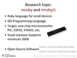
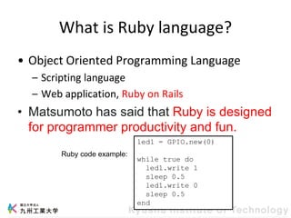
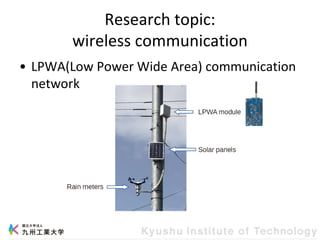
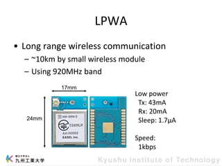
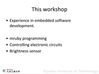
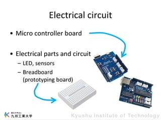
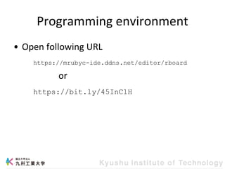
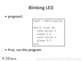
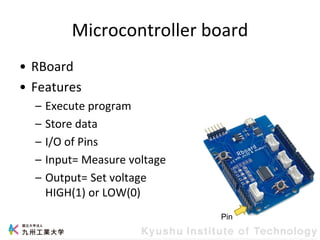
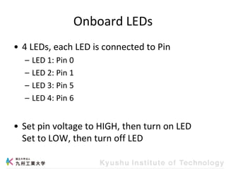
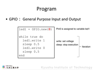
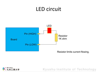
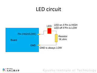
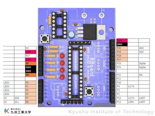
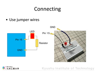
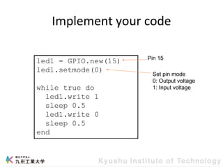
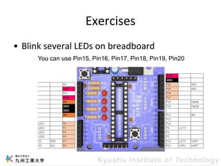
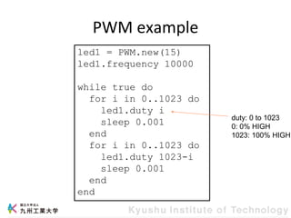
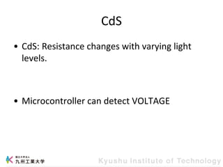
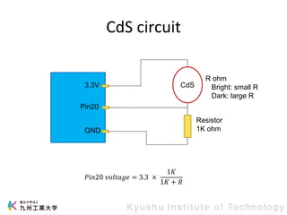
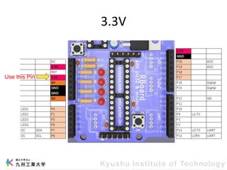
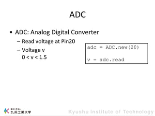
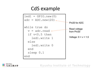
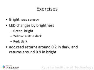
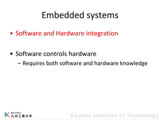

This document provides information about a workshop on mruby and embedded systems being held from September 11-15, 2023. The workshop will cover topics including mruby programming for small devices, controlling circuits with a microcontroller board, and using sensors like a brightness sensor. Attendees will learn to program an LED to blink and change brightness using mruby code, and will interface a CdS brightness sensor with a microcontroller to control an LED based on light levels. The workshop aims to give experience in embedded software development and interacting with electronic components like LEDs through programming.