Downloaded 339 times

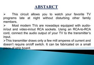


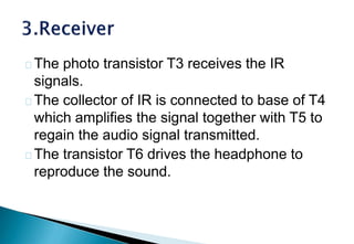


This document describes the design of a wireless audio transmitter for a TV using infrared transmission. The circuit allows watching TV late at night without disturbing others. It uses an IR transmitter connected to the TV's audio output to transmit the audio signal, and an IR receiver connected to a headphone to receive the signal. The circuit uses transistors, resistors, capacitors, and an IR transmitter and receiver module. It has advantages like low cost, low power consumption, and allowing quiet late-night TV viewing without disturbing others.