SlideShare a Scribd company logo
Abdelaziz B.M. Kamel Int. Journal of Engineering Research and Applications www.ijera.com 
ISSN : 2248-9622, Vol. 4, Issue 9( Version 6), September 2014, pp.159-166 
www.ijera.com 159|P a g e 
Calculation Method for Normal Inducedlongitudinal Voltage on Pilot Cable Abdelaziz B.M. Kamel, Ahmed R.E. Bakr Electrical Power Department, High Institute of Energy, Public Authority of Applied Education and Training, KUWAIT Abstract In this paper a full study and detailed calculations of the induced voltage in pilot cables are carried out. First an introduction showing the importance of the induced voltage and its effect in pilot cables. The first calculation method Flat Formation. The second calculation method Trefoil Formation. Then the results obtained for both methods and compared. Finally a conclusion is conduct. KeyWords: Induced Voltage, Normal Induced Longitudinal Voltage (NILV), Pilot cable 
I. Introduction 
Normal Induced Longitudinal Voltage (NILV) is generated onPilot Cable installed along with high tension Power Cable. Expectable sources of the inducing current which causes NILV are as follows: Three Phase Loading Current flowing in Power CableIn case that the distance between Power Cable and Pilot Cable installed are less than 2 or 3 meters, NILV on Pilot Cable is induced even If the three phase loading currents should be balanced. Earth Return Sheathing CurrentSheath current, which is induced by phase current, flows through the sheath of Power Cable. A part of this current flows through earth due to the phase to earth unbalance,although the sheath current has a screening effect against the induction due to the phase current. The current flowing through earth, which is called earth returning sheathcurrent, generally act as a screening current against the Induction due to the phase current . 
However, it also plays the main role of the inducing current for communication line in case that this runs more than several meters away from Power Cable. Normal Zero Phase CurrentSolidly grounded system is adopted in extra-high tension power line. Therefore, several percentage amount of zero-phase- current is generated, even in a normal condition, due to the unbalance in three phase loading current. This current flows through the ground ofsubstation and then is divided into two flows, one is the current which flows through the sheath of Power Cable and the other is the current which flows through earth. Only the latter (earth returning current) can act as inducing current, while it is very small in amount so as to benegligible. After all, only Three Phase Loading Current isconsiderable in case that Pilot Cable runs less than several meters away from Power Line. 
II. Calculation method for NILV 
Induced Voltage generated by Phase Loading Current 
V1=j ⍵ Ma1+z2.Mb1+z.Mc1 .l1 + z2.Ma2+z.Mb2+Mc2 .l2 + z.Ma3+ Mb3+ z2.Mc3 .l3 .IL.Ko (Volt)(1) 
RESEARCH ARTICLE OPEN ACCESS
Abdelaziz B.M. Kamel Int. Journal of Engineering Research and Applications www.ijera.com 
ISSN : 2248-9622, Vol. 4, Issue 9( Version 6), September 2014, pp.159-166 
www.ijera.com 160|P a g e 
Where V1 : NILV (Volt) ω: 2πf (f : Commercial Frequency (Hz)) Mij: Mutual Impedance between each phase circuit of Power Cableand Pilot Cable (H/km) lli:Equivalent Parallel Running Length of Power Cable and Pilot Cable (km) i.e.the length between the points of transposition dij:Distance between each phase circuit of Power Cable and Pilot Cable (cm) IL: Phase Current of Power Cable (A) Ko: Total Screening Factor Z :ej23π
Abdelaziz B.M. Kamel Int. Journal of Engineering Research and Applications www.ijera.com 
ISSN : 2248-9622, Vol. 4, Issue 9( Version 6), September 2014, pp.159-166 
www.ijera.com 161|P a g e 
When the transposition of three phase current circuits is adopted the induced voltage on Pilot can be derived from equation (1). And then using Carson-Pollazzek's formula, the following formula is obtained in case ofkd<0.5 . 1st term of equation (1) j ⍵ . Ma1+z2.Mb1+z.Mc1 .l1 =j ⍵ ( 4.6 log2k.da1−0.1544−jπ2 ) + z2 ( 4.6 log2k.db1−0.1544−jπ2 )+ z ( 4.6 log2k.dc1−0.1544−jπ2 ) .l1×10−4 =j ⍵(4.6) log2k.da1+ z2log2k.db1+ z log2k.dc1 .l1 ×10−4 Then 1 + z + z2=0 =j ⍵(4.6) log2k.da1− 12log2k.db1− j 32log2k.db1− 12log2k.dc1+ j 32log2k.dc1 .l1 ×10−4 =2.3 ⍵ 3 .logdc1db1−j.logda12db1 .dc1 l1 ×10−4 Note; k= 4πσω =2π 2dσ σ ;Earth Conductivity CGS emu generally σ= 10−12∶ 10−14 d : distance between power line and communication line (cm) Assume σ= 10−12 , f = 50 , d = 36 And then Kd = 0.0026 < 0.5 2nd term and 3rd term of equation(1) In the same manner as 1st term. jω (z2 . Ma2 + z.Mb2 + Mc2 ) .l2 = 2.3ω 3logdb2da2−j.logdc22da2 db2 .l2×10−4 jω z.Ma3+Mb3+ z2.Mc3 .l3 =2.3ω 3.logda3dc3−j.logdb3da3 dc3 .l3 ×10−4 Finally the following equation is obtained V1=2.3 ω.IL.ko×10−4 ( 3logdc1db1−j.logda12db1 .dc1).l1+( 3.logdb2da2−j.logdc22da2 db2 ).l2+( 3.logda3dc3− j.logdb32da3 dc3 ).l3(2) 
III. Typical Example Of calculation Of NILV 
The route profile and installation condition as in example 132KV power cable as shown in Fig.2 and Fig.3 respectively. The normal induced longitudinal voltage at each completed transpositioned span is calculated by equation 2. 3. 1 Flat Formation Substitute the following values for Equation2, ⍵= 2πf = 314.2 (f = 50) I_L = 670 (A) (max. current carrying capacity for flat formation) da1 = da2 = da3 = 36 (cm) = 3D (D = 12 cm) db1 = db2 = dbЗ= 24 (cm) = 2D dcl = dc2 = dc3 = 12 (cm) = D Ko = 0.9 (Taking the shielding effect caused by Wire Armourof Pilot Cable into account)
Abdelaziz B.M. Kamel Int. Journal of Engineering Research and Applications www.ijera.com 
ISSN : 2248-9622, Vol. 4, Issue 9( Version 6), September 2014, pp.159-166 
www.ijera.com 162|P a g e
Abdelaziz B.M. Kamel Int. Journal of Engineering Research and Applications www.ijera.com 
ISSN : 2248-9622, Vol. 4, Issue 9( Version 6), September 2014, pp.159-166 
www.ijera.com 163|P a g e 
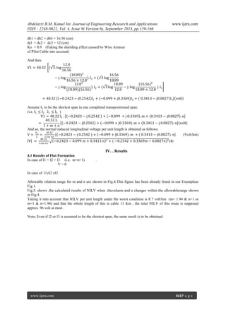
And then, V1=43.57 ( 3.logD2D−j.log(3D)2 2D .D).l1+( 3log2D3D−j.logD2(3D)(2D) ).l2+( 3log3DD−j.log(2D)2 3D .D ).l3 =43.57 −0.5214−j0.6532 .l1+ −0.3050+j0.7781 .l2+ 0.8264−j0.1249 .l3 Assume I1 to be the shortest span in one completed transpositioned span. (i.e. l1≤l2 ,l1≤l3 ) V1=43.57 l1 . −0.5214−j 0.6532 + −0.3050 +j 0.7781 .m+ 0.8264−j0.1249 .n = 43.57 L1+m+n −0.5214−j0.6532 + −0.3050+jo.7781 .m+ 0.8264−j 0.1249 .n volt Where;l1+ l2+ l3=L(one completed transpositioned length) l2l1=m ≥1 , l3l1=n ≥1 ∴1+m+n = Ll1 l1= L1+m+n And so, the normal induced longitudinal voltage per unit length is obtained as follows. V= V1L= 43.571+m+n −0.5214−j 0.6532 + −0.3050+j0.7781 .m + 0.8264−j0.1249 .n ( Volt / Km ) V = 43.571+m+n −0.5214−0.3050 m+0.8264 n 2+( −0.6532+0.7781m−0.1249n)2(3) 3.2 Trefoil Formation Substitute the following values for equation 2, ⍵= 2πf = 314.2 I_L = 620 (A) (current carrying capacity for trefoil formation) da1 = da2 = da3 = 18.89 (cm)
Abdelaziz B.M. Kamel Int. Journal of Engineering Research and Applications www.ijera.com 
ISSN : 2248-9622, Vol. 4, Issue 9( Version 6), September 2014, pp.159-166 
www.ijera.com 164|P a g e 
db1 = db2 = dbЗ = 16.56 (cm) dcl = dc2 = dc3 = 12 (cm) Ko = 0.9 (Taking the shielding effect caused by Wire Armour of Pilot Cable into account) And then V1=40.32 ( 3.log12.016.56−j.log(18.89)216.56×12.0).l1+( 3log16.5618.89−j.log12.02(18.89)(16.56) ).l2+( 3log18.8912.0−j.log(16.56)218.89×12.0 ).l3 =40.32 −0.2423−j0.2542 l1+ −0.099+j0.3369 l2+ 0.3413−j0.0827 l3 volt Assume I1 to be the shortest span in one completed transpositioned span. (i.e. l1≤l2 ,l1≤l3 ) V1=40.32 l1 . −0.2423−j 0.2542 + −0.099 +j 0.3369 .m+ 0.3413−j0.0827 .n = 40.32 L1+m+n −0.2423−j0.2542 + −0.099+j0.3369 .m+ 0.3413−j 0.0827 .n volt And so, the normal induced longitudinal voltage per unit length is obtained as follows. V= V1L= 40.321+m+n −0.2423−j 0.2542 + −0.099+j0.3369 .m + 0.3413−j0.0827 .n (Volt/km) V = 40.321+m+n −0.2423−0.099 m+0.3413 n 2+( −0.2542+0.3369m−0.0827n)2(4) 
IV. . Results 
4.1 Results of Flat Formation In case of l1 = l2 = l3 (i.e. m=n=1) . V = 0 In case of l1≠l2 ≠l3 Allowable relation range for m and n are shown in Fig.4.This figure has been already listed in our Exampleas Fig.1. Fig.5. shows .the calculated results of NILV when .thevaluem and n changes within the allowablerange shown in Fig.4. Taking it into account that NILV per unit length under the worst condition is 8.7 volt/km (m= 1.94 & n=1 or m=1 & n=1.94) and that the whole length of this is cable 11 Km , the total NILV of this route is supposed approx. 96 volt at most . Note; Even if l2 or l3 is assumed to be the shortest span, the same result is to be obtained.
Abdelaziz B.M. Kamel Int. Journal of Engineering Research and Applications www.ijera.com 
ISSN : 2248-9622, Vol. 4, Issue 9( Version 6), September 2014, pp.159-166 
www.ijera.com 165|P a g e 
4.2 Results of Trefoil Formation In case of l1= l2 = l3 (i.e. m=n=1) . V = 0 In case of l1≠l2 ≠l3 Allowable relation range for m and n are shown, in Fig.6. Fig.7. shows the calculated results of NILV when the value m and n changes within the allowable range in Fig.6. Taking it into account that NILV per unit length under the worst condition is 6.5 Volt/km (m = 3.52 & n=1 or m= 1 & n= 3.52) and that the whole length of this cable is 11 Km , the total NILV of this route is supposed approx. 72 Volt at most Note; Even if l2 or l3 is assumed to be the shortest span, the same result is to be Obtained.
Abdelaziz B.M. Kamel Int. Journal of Engineering Research and Applications www.ijera.com 
ISSN : 2248-9622, Vol. 4, Issue 9( Version 6), September 2014, pp.159-166 
www.ijera.com 166|P a g e 
V. Conclusion 
1. We conclude that to decrease the induced voltage across the pilot cable a cross-bonding method along with Trefoil method mentioned in the study in the installation of underground cables must be used. 2. Moreover, the induced voltage will not totally disappear and we need to protect the cable protection relays from it. 3. In practice to reduce the induced voltage and to isolate the fault a surge voltage limiters and transformer isolator are connected in the terminal block between pilot cable and protection relays. References [1] The underground systems reference book EEI,1957 [2] High voltage XLPE cables systems Technical user guide, BRUGG Cables. [3] CHEN shu-min,YANGLan- jun,ZHANGQiao-gen ,Su Hong-bo ,Li Yun- feng.Effect of sheath-bonding Method on Induced over voltage in 110 KV XLPE cable system in the case of ground fault surg (j). High voltage Engineering,2006. [4] Wang Min The induced voltage & circulating current in the metal shield of 10 KV sigle phase electrical cables (j). High voltage Engineering,2006. [5] P.L. Ostermann, Editor, Underground Transmission systems reference book ,NewYork :Electric Power Research Institute,1992 Edition. [6] IEEE Guide for Application of sheath- Bonding Methods for single conductor cables and calculation of induced voltage and currents in cables sheaths ,IEEEStandard,March 1986. [7] Electrical Transmission & Distribution reference book ,Westinghouse Electric Corportion,1964.

More Related Content

What's hot

ACCURATE Q-PREDICTION FOR RFIC SPIRAL INDUCTORS USING THE 3DB BANDWIDTH
ACCURATE Q-PREDICTION FOR RFIC SPIRAL INDUCTORS  USING THE 3DB BANDWIDTHACCURATE Q-PREDICTION FOR RFIC SPIRAL INDUCTORS  USING THE 3DB BANDWIDTH
ACCURATE Q-PREDICTION FOR RFIC SPIRAL INDUCTORS USING THE 3DB BANDWIDTH
Ilango Jeyasubramanian
 
Lecture 13
Lecture 13Lecture 13
Lecture 13
Forward2025
 
Elecmachine
ElecmachineElecmachine
Elecmachine
Hassan Tirmizi
 
Lecture 6
Lecture 6Lecture 6
Lecture 6
Forward2025
 
Cable sizing to withstand short circuit current
Cable sizing to withstand short circuit currentCable sizing to withstand short circuit current
Cable sizing to withstand short circuit current
Leonardo ENERGY
 
Lecture 3
Lecture 3Lecture 3
Lecture 3
Forward2025
 
Lecture 18
Lecture 18Lecture 18
Lecture 18
Forward2025
 
Magnetic Force and Material Media
Magnetic Force and Material MediaMagnetic Force and Material Media
Magnetic Force and Material Media
kailash karki
 
DESIGNED A 350NM TWO STAGE OPERATIONAL AMPLIFIER
DESIGNED A 350NM TWO STAGE OPERATIONAL AMPLIFIERDESIGNED A 350NM TWO STAGE OPERATIONAL AMPLIFIER
DESIGNED A 350NM TWO STAGE OPERATIONAL AMPLIFIER
Ilango Jeyasubramanian
 
Transmission lines
Transmission linesTransmission lines
Transmission lines
kailash karki
 
Lecture 8
Lecture 8Lecture 8
Lecture 8
Forward2025
 
ECNG 3013 B
ECNG 3013 BECNG 3013 B
ECNG 3013 B
Chandrabhan Sharma
 
New generation of copper conductors for overhead lines
New generation of copper conductors for overhead linesNew generation of copper conductors for overhead lines
New generation of copper conductors for overhead lines
Leonardo ENERGY
 
Lecture 11
Lecture 11Lecture 11
Lecture 11
Forward2025
 
Lecture 12
Lecture 12Lecture 12
Lecture 12
Forward2025
 
Transformer design 2072 batch IOE - TU
Transformer design 2072 batch IOE - TU Transformer design 2072 batch IOE - TU
Transformer design 2072 batch IOE - TU
Bikash Gyawali
 
Chap2 s11b
Chap2 s11bChap2 s11b
Chap2 s11b
Ibrahim Khleifat
 
ECNG 3013 E
ECNG 3013 EECNG 3013 E
ECNG 3013 E
Chandrabhan Sharma
 
Lecture 7
Lecture 7Lecture 7
Lecture 7
Forward2025
 
De icing of high voltage lines
De icing of high voltage linesDe icing of high voltage lines
De icing of high voltage lines
Souvik Dutta
 

What's hot (20)

ACCURATE Q-PREDICTION FOR RFIC SPIRAL INDUCTORS USING THE 3DB BANDWIDTH
ACCURATE Q-PREDICTION FOR RFIC SPIRAL INDUCTORS  USING THE 3DB BANDWIDTHACCURATE Q-PREDICTION FOR RFIC SPIRAL INDUCTORS  USING THE 3DB BANDWIDTH
ACCURATE Q-PREDICTION FOR RFIC SPIRAL INDUCTORS USING THE 3DB BANDWIDTH
 
Lecture 13
Lecture 13Lecture 13
Lecture 13
 
Elecmachine
ElecmachineElecmachine
Elecmachine
 
Lecture 6
Lecture 6Lecture 6
Lecture 6
 
Cable sizing to withstand short circuit current
Cable sizing to withstand short circuit currentCable sizing to withstand short circuit current
Cable sizing to withstand short circuit current
 
Lecture 3
Lecture 3Lecture 3
Lecture 3
 
Lecture 18
Lecture 18Lecture 18
Lecture 18
 
Magnetic Force and Material Media
Magnetic Force and Material MediaMagnetic Force and Material Media
Magnetic Force and Material Media
 
DESIGNED A 350NM TWO STAGE OPERATIONAL AMPLIFIER
DESIGNED A 350NM TWO STAGE OPERATIONAL AMPLIFIERDESIGNED A 350NM TWO STAGE OPERATIONAL AMPLIFIER
DESIGNED A 350NM TWO STAGE OPERATIONAL AMPLIFIER
 
Transmission lines
Transmission linesTransmission lines
Transmission lines
 
Lecture 8
Lecture 8Lecture 8
Lecture 8
 
ECNG 3013 B
ECNG 3013 BECNG 3013 B
ECNG 3013 B
 
New generation of copper conductors for overhead lines
New generation of copper conductors for overhead linesNew generation of copper conductors for overhead lines
New generation of copper conductors for overhead lines
 
Lecture 11
Lecture 11Lecture 11
Lecture 11
 
Lecture 12
Lecture 12Lecture 12
Lecture 12
 
Transformer design 2072 batch IOE - TU
Transformer design 2072 batch IOE - TU Transformer design 2072 batch IOE - TU
Transformer design 2072 batch IOE - TU
 
Chap2 s11b
Chap2 s11bChap2 s11b
Chap2 s11b
 
ECNG 3013 E
ECNG 3013 EECNG 3013 E
ECNG 3013 E
 
Lecture 7
Lecture 7Lecture 7
Lecture 7
 
De icing of high voltage lines
De icing of high voltage linesDe icing of high voltage lines
De icing of high voltage lines
 

Viewers also liked

Multi-Channel vs. Pure e-Play: Werden wir alle zu digitalen Non-Stop-Shoppern?
Multi-Channel vs. Pure e-Play: Werden wir alle zu digitalen Non-Stop-Shoppern?Multi-Channel vs. Pure e-Play: Werden wir alle zu digitalen Non-Stop-Shoppern?
Multi-Channel vs. Pure e-Play: Werden wir alle zu digitalen Non-Stop-Shoppern?Jochen Krisch
 
Bom de bíblia 2012 10
Bom de bíblia 2012 10Bom de bíblia 2012 10
Bom de bíblia 2012 10
Ton BSantos
 
Slidershare caro
Slidershare caroSlidershare caro
Slidershare caro
Cele's Jiménez
 
Escuela normal superior de medellín
Escuela normal superior de medellínEscuela normal superior de medellín
Escuela normal superior de medellín
Ana Maria
 
Limitación visual
Limitación visualLimitación visual
Limitación visual
María Eugenia Gallo Arbeláez
 
Transparenzfalle Internet - Wie sich Händler unverwechselbarer machen
Transparenzfalle Internet - Wie sich Händler unverwechselbarer machenTransparenzfalle Internet - Wie sich Händler unverwechselbarer machen
Transparenzfalle Internet - Wie sich Händler unverwechselbarer machen
Jochen Krisch
 
Manual tejeRedes parte I redes y comunidades colaborativas
Manual tejeRedes parte I redes y comunidades  colaborativasManual tejeRedes parte I redes y comunidades  colaborativas
Manual tejeRedes parte I redes y comunidades colaborativas
tejeRedes
 
TWDRBSThe walkingdead brasil-001_pt
TWDRBSThe walkingdead brasil-001_ptTWDRBSThe walkingdead brasil-001_pt
TWDRBSThe walkingdead brasil-001_pt
Azhroth B.S
 
Impacts of Urban Land use changes on flood events in Warri, Delta State Nigeria
Impacts of Urban Land use changes on flood events in Warri, Delta State NigeriaImpacts of Urban Land use changes on flood events in Warri, Delta State Nigeria
Impacts of Urban Land use changes on flood events in Warri, Delta State Nigeria
IJERA Editor
 
On Semi-Invariant Submanifolds of a Nearly Hyperbolic Kenmotsu Manifold with ...
On Semi-Invariant Submanifolds of a Nearly Hyperbolic Kenmotsu Manifold with ...On Semi-Invariant Submanifolds of a Nearly Hyperbolic Kenmotsu Manifold with ...
On Semi-Invariant Submanifolds of a Nearly Hyperbolic Kenmotsu Manifold with ...
IJERA Editor
 
Matthias Weber, Образование взрослых в Восточной Германии на примере земли Са...
Matthias Weber, Образование взрослых в Восточной Германии на примере земли Са...Matthias Weber, Образование взрослых в Восточной Германии на примере земли Са...
Matthias Weber, Образование взрослых в Восточной Германии на примере земли Са...
Alianta INFONET
 
Organización de las naciones unidas
Organización de las naciones unidasOrganización de las naciones unidas
Organización de las naciones unidas
110165
 
Convenio colectivo de instalaciones deportivas 2006
Convenio colectivo de instalaciones deportivas 2006Convenio colectivo de instalaciones deportivas 2006
Convenio colectivo de instalaciones deportivas 2006
kirolkudeaketa
 
Bonsai (Nx Power Lite) Lr
Bonsai (Nx Power Lite) LrBonsai (Nx Power Lite) Lr
Bonsai (Nx Power Lite) Lr
mariane m
 
Contaminacion acustica y tala grupo 5
Contaminacion acustica y tala grupo 5Contaminacion acustica y tala grupo 5
Contaminacion acustica y tala grupo 5
Jose Indraya
 
Bom de bíblia 2012 17
Bom de bíblia 2012 17Bom de bíblia 2012 17
Bom de bíblia 2012 17
Ton BSantos
 
Freshness
FreshnessFreshness
Freshness
Manuela Szekely
 
Amazing Nature Pictures
Amazing Nature PicturesAmazing Nature Pictures
Amazing Nature Pictures
mariane m
 
Viaje a Burgos
Viaje a BurgosViaje a Burgos
Viaje a Burgos
srbenito
 

Viewers also liked (20)

Multi-Channel vs. Pure e-Play: Werden wir alle zu digitalen Non-Stop-Shoppern?
Multi-Channel vs. Pure e-Play: Werden wir alle zu digitalen Non-Stop-Shoppern?Multi-Channel vs. Pure e-Play: Werden wir alle zu digitalen Non-Stop-Shoppern?
Multi-Channel vs. Pure e-Play: Werden wir alle zu digitalen Non-Stop-Shoppern?
 
Bom de bíblia 2012 10
Bom de bíblia 2012 10Bom de bíblia 2012 10
Bom de bíblia 2012 10
 
Slidershare caro
Slidershare caroSlidershare caro
Slidershare caro
 
Escuela normal superior de medellín
Escuela normal superior de medellínEscuela normal superior de medellín
Escuela normal superior de medellín
 
Limitación visual
Limitación visualLimitación visual
Limitación visual
 
Transparenzfalle Internet - Wie sich Händler unverwechselbarer machen
Transparenzfalle Internet - Wie sich Händler unverwechselbarer machenTransparenzfalle Internet - Wie sich Händler unverwechselbarer machen
Transparenzfalle Internet - Wie sich Händler unverwechselbarer machen
 
Manual tejeRedes parte I redes y comunidades colaborativas
Manual tejeRedes parte I redes y comunidades  colaborativasManual tejeRedes parte I redes y comunidades  colaborativas
Manual tejeRedes parte I redes y comunidades colaborativas
 
Test
TestTest
Test
 
TWDRBSThe walkingdead brasil-001_pt
TWDRBSThe walkingdead brasil-001_ptTWDRBSThe walkingdead brasil-001_pt
TWDRBSThe walkingdead brasil-001_pt
 
Impacts of Urban Land use changes on flood events in Warri, Delta State Nigeria
Impacts of Urban Land use changes on flood events in Warri, Delta State NigeriaImpacts of Urban Land use changes on flood events in Warri, Delta State Nigeria
Impacts of Urban Land use changes on flood events in Warri, Delta State Nigeria
 
On Semi-Invariant Submanifolds of a Nearly Hyperbolic Kenmotsu Manifold with ...
On Semi-Invariant Submanifolds of a Nearly Hyperbolic Kenmotsu Manifold with ...On Semi-Invariant Submanifolds of a Nearly Hyperbolic Kenmotsu Manifold with ...
On Semi-Invariant Submanifolds of a Nearly Hyperbolic Kenmotsu Manifold with ...
 
Matthias Weber, Образование взрослых в Восточной Германии на примере земли Са...
Matthias Weber, Образование взрослых в Восточной Германии на примере земли Са...Matthias Weber, Образование взрослых в Восточной Германии на примере земли Са...
Matthias Weber, Образование взрослых в Восточной Германии на примере земли Са...
 
Organización de las naciones unidas
Organización de las naciones unidasOrganización de las naciones unidas
Organización de las naciones unidas
 
Convenio colectivo de instalaciones deportivas 2006
Convenio colectivo de instalaciones deportivas 2006Convenio colectivo de instalaciones deportivas 2006
Convenio colectivo de instalaciones deportivas 2006
 
Bonsai (Nx Power Lite) Lr
Bonsai (Nx Power Lite) LrBonsai (Nx Power Lite) Lr
Bonsai (Nx Power Lite) Lr
 
Contaminacion acustica y tala grupo 5
Contaminacion acustica y tala grupo 5Contaminacion acustica y tala grupo 5
Contaminacion acustica y tala grupo 5
 
Bom de bíblia 2012 17
Bom de bíblia 2012 17Bom de bíblia 2012 17
Bom de bíblia 2012 17
 
Freshness
FreshnessFreshness
Freshness
 
Amazing Nature Pictures
Amazing Nature PicturesAmazing Nature Pictures
Amazing Nature Pictures
 
Viaje a Burgos
Viaje a BurgosViaje a Burgos
Viaje a Burgos
 

Similar to Calculation Method for Normal Inducedlongitudinal Voltage on Pilot Cable

Ci33514517
Ci33514517Ci33514517
Ci33514517
IJERA Editor
 
Ci33514517
Ci33514517Ci33514517
Ci33514517
IJERA Editor
 
Ci33514517
Ci33514517Ci33514517
Ci33514517
IJERA Editor
 
Modeling and Analysis of a 3-Phase 132kv GasInsulated Substation
Modeling and Analysis of a 3-Phase 132kv GasInsulated SubstationModeling and Analysis of a 3-Phase 132kv GasInsulated Substation
Modeling and Analysis of a 3-Phase 132kv GasInsulated Substation
IRJET Journal
 
Conducted electromagnetic interference mitigation in super-lift Luo-converte...
Conducted electromagnetic interference mitigation in super-lift  Luo-converte...Conducted electromagnetic interference mitigation in super-lift  Luo-converte...
Conducted electromagnetic interference mitigation in super-lift Luo-converte...
IJECEIAES
 
Design & performance of six pulse voltage multipliers 2
Design & performance of six pulse voltage multipliers 2Design & performance of six pulse voltage multipliers 2
Design & performance of six pulse voltage multipliers 2
IAEME Publication
 
Chapter 4 Transmission.ppt
Chapter 4 Transmission.pptChapter 4 Transmission.ppt
Chapter 4 Transmission.ppt
LiewChiaPing
 
transmission line theory prp
transmission line theory prptransmission line theory prp
transmission line theory prp
Dr. Pravin Prajapati
 
Ehv line design
Ehv line designEhv line design
Ehv line design
Demsew Mitiku
 
A novel voltage reference without the operational amplifier and resistors
A novel voltage reference without the operational amplifier and resistorsA novel voltage reference without the operational amplifier and resistors
A novel voltage reference without the operational amplifier and resistors
IJRES Journal
 
IJEDR1601085
IJEDR1601085IJEDR1601085
IJEDR1601085
Ameer Haert
 
Evaluating the Synchronization of a Chaotic Encryption Scheme Using Different...
Evaluating the Synchronization of a Chaotic Encryption Scheme Using Different...Evaluating the Synchronization of a Chaotic Encryption Scheme Using Different...
Evaluating the Synchronization of a Chaotic Encryption Scheme Using Different...
IOSR Journals
 
F010123235
F010123235F010123235
F010123235
IOSR Journals
 
8 526-536
8 526-5368 526-536
8 526-536
idescitation
 
Comparative detection and fault location in underground cables using Fourier...
Comparative detection and fault location in underground cables  using Fourier...Comparative detection and fault location in underground cables  using Fourier...
Comparative detection and fault location in underground cables using Fourier...
IJECEIAES
 
IRJET- FPGA Controlled Three Level Diode Clamped Multilevel Inverter for Sola...
IRJET- FPGA Controlled Three Level Diode Clamped Multilevel Inverter for Sola...IRJET- FPGA Controlled Three Level Diode Clamped Multilevel Inverter for Sola...
IRJET- FPGA Controlled Three Level Diode Clamped Multilevel Inverter for Sola...
IRJET Journal
 
Analysis and Modeling of Transformerless Photovoltaic Inverter Systems
Analysis and Modeling of Transformerless Photovoltaic Inverter SystemsAnalysis and Modeling of Transformerless Photovoltaic Inverter Systems
Analysis and Modeling of Transformerless Photovoltaic Inverter Systems
IJMER
 
wep153
wep153wep153
A modified Cuk DC-DC converter for DC microgrid systems
A modified Cuk DC-DC converter for DC microgrid systemsA modified Cuk DC-DC converter for DC microgrid systems
A modified Cuk DC-DC converter for DC microgrid systems
TELKOMNIKA JOURNAL
 
S ag calc
S ag calcS ag calc
S ag calc
anurag pugalia
 

Similar to Calculation Method for Normal Inducedlongitudinal Voltage on Pilot Cable (20)

Ci33514517
Ci33514517Ci33514517
Ci33514517
 
Ci33514517
Ci33514517Ci33514517
Ci33514517
 
Ci33514517
Ci33514517Ci33514517
Ci33514517
 
Modeling and Analysis of a 3-Phase 132kv GasInsulated Substation
Modeling and Analysis of a 3-Phase 132kv GasInsulated SubstationModeling and Analysis of a 3-Phase 132kv GasInsulated Substation
Modeling and Analysis of a 3-Phase 132kv GasInsulated Substation
 
Conducted electromagnetic interference mitigation in super-lift Luo-converte...
Conducted electromagnetic interference mitigation in super-lift  Luo-converte...Conducted electromagnetic interference mitigation in super-lift  Luo-converte...
Conducted electromagnetic interference mitigation in super-lift Luo-converte...
 
Design & performance of six pulse voltage multipliers 2
Design & performance of six pulse voltage multipliers 2Design & performance of six pulse voltage multipliers 2
Design & performance of six pulse voltage multipliers 2
 
Chapter 4 Transmission.ppt
Chapter 4 Transmission.pptChapter 4 Transmission.ppt
Chapter 4 Transmission.ppt
 
transmission line theory prp
transmission line theory prptransmission line theory prp
transmission line theory prp
 
Ehv line design
Ehv line designEhv line design
Ehv line design
 
A novel voltage reference without the operational amplifier and resistors
A novel voltage reference without the operational amplifier and resistorsA novel voltage reference without the operational amplifier and resistors
A novel voltage reference without the operational amplifier and resistors
 
IJEDR1601085
IJEDR1601085IJEDR1601085
IJEDR1601085
 
Evaluating the Synchronization of a Chaotic Encryption Scheme Using Different...
Evaluating the Synchronization of a Chaotic Encryption Scheme Using Different...Evaluating the Synchronization of a Chaotic Encryption Scheme Using Different...
Evaluating the Synchronization of a Chaotic Encryption Scheme Using Different...
 
F010123235
F010123235F010123235
F010123235
 
8 526-536
8 526-5368 526-536
8 526-536
 
Comparative detection and fault location in underground cables using Fourier...
Comparative detection and fault location in underground cables  using Fourier...Comparative detection and fault location in underground cables  using Fourier...
Comparative detection and fault location in underground cables using Fourier...
 
IRJET- FPGA Controlled Three Level Diode Clamped Multilevel Inverter for Sola...
IRJET- FPGA Controlled Three Level Diode Clamped Multilevel Inverter for Sola...IRJET- FPGA Controlled Three Level Diode Clamped Multilevel Inverter for Sola...
IRJET- FPGA Controlled Three Level Diode Clamped Multilevel Inverter for Sola...
 
Analysis and Modeling of Transformerless Photovoltaic Inverter Systems
Analysis and Modeling of Transformerless Photovoltaic Inverter SystemsAnalysis and Modeling of Transformerless Photovoltaic Inverter Systems
Analysis and Modeling of Transformerless Photovoltaic Inverter Systems
 
wep153
wep153wep153
wep153
 
A modified Cuk DC-DC converter for DC microgrid systems
A modified Cuk DC-DC converter for DC microgrid systemsA modified Cuk DC-DC converter for DC microgrid systems
A modified Cuk DC-DC converter for DC microgrid systems
 
S ag calc
S ag calcS ag calc
S ag calc
 

Recently uploaded

Iron and Steel Technology Roadmap - Towards more sustainable steelmaking.pdf
Iron and Steel Technology Roadmap - Towards more sustainable steelmaking.pdfIron and Steel Technology Roadmap - Towards more sustainable steelmaking.pdf
Iron and Steel Technology Roadmap - Towards more sustainable steelmaking.pdf
RadiNasr
 
Wearable antenna for antenna applications
Wearable antenna for antenna applicationsWearable antenna for antenna applications
Wearable antenna for antenna applications
Madhumitha Jayaram
 
[JPP-1] - (JEE 3.0) - Kinematics 1D - 14th May..pdf
[JPP-1] - (JEE 3.0) - Kinematics 1D - 14th May..pdf[JPP-1] - (JEE 3.0) - Kinematics 1D - 14th May..pdf
[JPP-1] - (JEE 3.0) - Kinematics 1D - 14th May..pdf
awadeshbabu
 
A review on techniques and modelling methodologies used for checking electrom...
A review on techniques and modelling methodologies used for checking electrom...A review on techniques and modelling methodologies used for checking electrom...
A review on techniques and modelling methodologies used for checking electrom...
nooriasukmaningtyas
 
basic-wireline-operations-course-mahmoud-f-radwan.pdf
basic-wireline-operations-course-mahmoud-f-radwan.pdfbasic-wireline-operations-course-mahmoud-f-radwan.pdf
basic-wireline-operations-course-mahmoud-f-radwan.pdf
NidhalKahouli2
 
Series of visio cisco devices Cisco_Icons.ppt
Series of visio cisco devices Cisco_Icons.pptSeries of visio cisco devices Cisco_Icons.ppt
Series of visio cisco devices Cisco_Icons.ppt
PauloRodrigues104553
 
Harnessing WebAssembly for Real-time Stateless Streaming Pipelines
Harnessing WebAssembly for Real-time Stateless Streaming PipelinesHarnessing WebAssembly for Real-time Stateless Streaming Pipelines
Harnessing WebAssembly for Real-time Stateless Streaming Pipelines
Christina Lin
 
Modelagem de um CSTR com reação endotermica.pdf
Modelagem de um CSTR com reação endotermica.pdfModelagem de um CSTR com reação endotermica.pdf
Modelagem de um CSTR com reação endotermica.pdf
camseq
 
DfMAy 2024 - key insights and contributions
DfMAy 2024 - key insights and contributionsDfMAy 2024 - key insights and contributions
DfMAy 2024 - key insights and contributions
gestioneergodomus
 
Embedded machine learning-based road conditions and driving behavior monitoring
Embedded machine learning-based road conditions and driving behavior monitoringEmbedded machine learning-based road conditions and driving behavior monitoring
Embedded machine learning-based road conditions and driving behavior monitoring
IJECEIAES
 
Electric vehicle and photovoltaic advanced roles in enhancing the financial p...
Electric vehicle and photovoltaic advanced roles in enhancing the financial p...Electric vehicle and photovoltaic advanced roles in enhancing the financial p...
Electric vehicle and photovoltaic advanced roles in enhancing the financial p...
IJECEIAES
 
6th International Conference on Machine Learning & Applications (CMLA 2024)
6th International Conference on Machine Learning & Applications (CMLA 2024)6th International Conference on Machine Learning & Applications (CMLA 2024)
6th International Conference on Machine Learning & Applications (CMLA 2024)
ClaraZara1
 
Recycled Concrete Aggregate in Construction Part III
Recycled Concrete Aggregate in Construction Part IIIRecycled Concrete Aggregate in Construction Part III
Recycled Concrete Aggregate in Construction Part III
Aditya Rajan Patra
 
digital fundamental by Thomas L.floydl.pdf
digital fundamental by Thomas L.floydl.pdfdigital fundamental by Thomas L.floydl.pdf
digital fundamental by Thomas L.floydl.pdf
drwaing
 
bank management system in java and mysql report1.pdf
bank management system in java and mysql report1.pdfbank management system in java and mysql report1.pdf
bank management system in java and mysql report1.pdf
Divyam548318
 
DEEP LEARNING FOR SMART GRID INTRUSION DETECTION: A HYBRID CNN-LSTM-BASED MODEL
DEEP LEARNING FOR SMART GRID INTRUSION DETECTION: A HYBRID CNN-LSTM-BASED MODELDEEP LEARNING FOR SMART GRID INTRUSION DETECTION: A HYBRID CNN-LSTM-BASED MODEL
DEEP LEARNING FOR SMART GRID INTRUSION DETECTION: A HYBRID CNN-LSTM-BASED MODEL
gerogepatton
 
RAT: Retrieval Augmented Thoughts Elicit Context-Aware Reasoning in Long-Hori...
RAT: Retrieval Augmented Thoughts Elicit Context-Aware Reasoning in Long-Hori...RAT: Retrieval Augmented Thoughts Elicit Context-Aware Reasoning in Long-Hori...
RAT: Retrieval Augmented Thoughts Elicit Context-Aware Reasoning in Long-Hori...
thanhdowork
 
Literature Review Basics and Understanding Reference Management.pptx
Literature Review Basics and Understanding Reference Management.pptxLiterature Review Basics and Understanding Reference Management.pptx
Literature Review Basics and Understanding Reference Management.pptx
Dr Ramhari Poudyal
 
Swimming pool mechanical components design.pptx
Swimming pool  mechanical components design.pptxSwimming pool  mechanical components design.pptx
Swimming pool mechanical components design.pptx
yokeleetan1
 
International Conference on NLP, Artificial Intelligence, Machine Learning an...
International Conference on NLP, Artificial Intelligence, Machine Learning an...International Conference on NLP, Artificial Intelligence, Machine Learning an...
International Conference on NLP, Artificial Intelligence, Machine Learning an...
gerogepatton
 

Recently uploaded (20)

Iron and Steel Technology Roadmap - Towards more sustainable steelmaking.pdf
Iron and Steel Technology Roadmap - Towards more sustainable steelmaking.pdfIron and Steel Technology Roadmap - Towards more sustainable steelmaking.pdf
Iron and Steel Technology Roadmap - Towards more sustainable steelmaking.pdf
 
Wearable antenna for antenna applications
Wearable antenna for antenna applicationsWearable antenna for antenna applications
Wearable antenna for antenna applications
 
[JPP-1] - (JEE 3.0) - Kinematics 1D - 14th May..pdf
[JPP-1] - (JEE 3.0) - Kinematics 1D - 14th May..pdf[JPP-1] - (JEE 3.0) - Kinematics 1D - 14th May..pdf
[JPP-1] - (JEE 3.0) - Kinematics 1D - 14th May..pdf
 
A review on techniques and modelling methodologies used for checking electrom...
A review on techniques and modelling methodologies used for checking electrom...A review on techniques and modelling methodologies used for checking electrom...
A review on techniques and modelling methodologies used for checking electrom...
 
basic-wireline-operations-course-mahmoud-f-radwan.pdf
basic-wireline-operations-course-mahmoud-f-radwan.pdfbasic-wireline-operations-course-mahmoud-f-radwan.pdf
basic-wireline-operations-course-mahmoud-f-radwan.pdf
 
Series of visio cisco devices Cisco_Icons.ppt
Series of visio cisco devices Cisco_Icons.pptSeries of visio cisco devices Cisco_Icons.ppt
Series of visio cisco devices Cisco_Icons.ppt
 
Harnessing WebAssembly for Real-time Stateless Streaming Pipelines
Harnessing WebAssembly for Real-time Stateless Streaming PipelinesHarnessing WebAssembly for Real-time Stateless Streaming Pipelines
Harnessing WebAssembly for Real-time Stateless Streaming Pipelines
 
Modelagem de um CSTR com reação endotermica.pdf
Modelagem de um CSTR com reação endotermica.pdfModelagem de um CSTR com reação endotermica.pdf
Modelagem de um CSTR com reação endotermica.pdf
 
DfMAy 2024 - key insights and contributions
DfMAy 2024 - key insights and contributionsDfMAy 2024 - key insights and contributions
DfMAy 2024 - key insights and contributions
 
Embedded machine learning-based road conditions and driving behavior monitoring
Embedded machine learning-based road conditions and driving behavior monitoringEmbedded machine learning-based road conditions and driving behavior monitoring
Embedded machine learning-based road conditions and driving behavior monitoring
 
Electric vehicle and photovoltaic advanced roles in enhancing the financial p...
Electric vehicle and photovoltaic advanced roles in enhancing the financial p...Electric vehicle and photovoltaic advanced roles in enhancing the financial p...
Electric vehicle and photovoltaic advanced roles in enhancing the financial p...
 
6th International Conference on Machine Learning & Applications (CMLA 2024)
6th International Conference on Machine Learning & Applications (CMLA 2024)6th International Conference on Machine Learning & Applications (CMLA 2024)
6th International Conference on Machine Learning & Applications (CMLA 2024)
 
Recycled Concrete Aggregate in Construction Part III
Recycled Concrete Aggregate in Construction Part IIIRecycled Concrete Aggregate in Construction Part III
Recycled Concrete Aggregate in Construction Part III
 
digital fundamental by Thomas L.floydl.pdf
digital fundamental by Thomas L.floydl.pdfdigital fundamental by Thomas L.floydl.pdf
digital fundamental by Thomas L.floydl.pdf
 
bank management system in java and mysql report1.pdf
bank management system in java and mysql report1.pdfbank management system in java and mysql report1.pdf
bank management system in java and mysql report1.pdf
 
DEEP LEARNING FOR SMART GRID INTRUSION DETECTION: A HYBRID CNN-LSTM-BASED MODEL
DEEP LEARNING FOR SMART GRID INTRUSION DETECTION: A HYBRID CNN-LSTM-BASED MODELDEEP LEARNING FOR SMART GRID INTRUSION DETECTION: A HYBRID CNN-LSTM-BASED MODEL
DEEP LEARNING FOR SMART GRID INTRUSION DETECTION: A HYBRID CNN-LSTM-BASED MODEL
 
RAT: Retrieval Augmented Thoughts Elicit Context-Aware Reasoning in Long-Hori...
RAT: Retrieval Augmented Thoughts Elicit Context-Aware Reasoning in Long-Hori...RAT: Retrieval Augmented Thoughts Elicit Context-Aware Reasoning in Long-Hori...
RAT: Retrieval Augmented Thoughts Elicit Context-Aware Reasoning in Long-Hori...
 
Literature Review Basics and Understanding Reference Management.pptx
Literature Review Basics and Understanding Reference Management.pptxLiterature Review Basics and Understanding Reference Management.pptx
Literature Review Basics and Understanding Reference Management.pptx
 
Swimming pool mechanical components design.pptx
Swimming pool  mechanical components design.pptxSwimming pool  mechanical components design.pptx
Swimming pool mechanical components design.pptx
 
International Conference on NLP, Artificial Intelligence, Machine Learning an...
International Conference on NLP, Artificial Intelligence, Machine Learning an...International Conference on NLP, Artificial Intelligence, Machine Learning an...
International Conference on NLP, Artificial Intelligence, Machine Learning an...
 

Calculation Method for Normal Inducedlongitudinal Voltage on Pilot Cable

  • 1. Abdelaziz B.M. Kamel Int. Journal of Engineering Research and Applications www.ijera.com ISSN : 2248-9622, Vol. 4, Issue 9( Version 6), September 2014, pp.159-166 www.ijera.com 159|P a g e Calculation Method for Normal Inducedlongitudinal Voltage on Pilot Cable Abdelaziz B.M. Kamel, Ahmed R.E. Bakr Electrical Power Department, High Institute of Energy, Public Authority of Applied Education and Training, KUWAIT Abstract In this paper a full study and detailed calculations of the induced voltage in pilot cables are carried out. First an introduction showing the importance of the induced voltage and its effect in pilot cables. The first calculation method Flat Formation. The second calculation method Trefoil Formation. Then the results obtained for both methods and compared. Finally a conclusion is conduct. KeyWords: Induced Voltage, Normal Induced Longitudinal Voltage (NILV), Pilot cable I. Introduction Normal Induced Longitudinal Voltage (NILV) is generated onPilot Cable installed along with high tension Power Cable. Expectable sources of the inducing current which causes NILV are as follows: Three Phase Loading Current flowing in Power CableIn case that the distance between Power Cable and Pilot Cable installed are less than 2 or 3 meters, NILV on Pilot Cable is induced even If the three phase loading currents should be balanced. Earth Return Sheathing CurrentSheath current, which is induced by phase current, flows through the sheath of Power Cable. A part of this current flows through earth due to the phase to earth unbalance,although the sheath current has a screening effect against the induction due to the phase current. The current flowing through earth, which is called earth returning sheathcurrent, generally act as a screening current against the Induction due to the phase current . However, it also plays the main role of the inducing current for communication line in case that this runs more than several meters away from Power Cable. Normal Zero Phase CurrentSolidly grounded system is adopted in extra-high tension power line. Therefore, several percentage amount of zero-phase- current is generated, even in a normal condition, due to the unbalance in three phase loading current. This current flows through the ground ofsubstation and then is divided into two flows, one is the current which flows through the sheath of Power Cable and the other is the current which flows through earth. Only the latter (earth returning current) can act as inducing current, while it is very small in amount so as to benegligible. After all, only Three Phase Loading Current isconsiderable in case that Pilot Cable runs less than several meters away from Power Line. II. Calculation method for NILV Induced Voltage generated by Phase Loading Current V1=j ⍵ Ma1+z2.Mb1+z.Mc1 .l1 + z2.Ma2+z.Mb2+Mc2 .l2 + z.Ma3+ Mb3+ z2.Mc3 .l3 .IL.Ko (Volt)(1) RESEARCH ARTICLE OPEN ACCESS
  • 2. Abdelaziz B.M. Kamel Int. Journal of Engineering Research and Applications www.ijera.com ISSN : 2248-9622, Vol. 4, Issue 9( Version 6), September 2014, pp.159-166 www.ijera.com 160|P a g e Where V1 : NILV (Volt) ω: 2πf (f : Commercial Frequency (Hz)) Mij: Mutual Impedance between each phase circuit of Power Cableand Pilot Cable (H/km) lli:Equivalent Parallel Running Length of Power Cable and Pilot Cable (km) i.e.the length between the points of transposition dij:Distance between each phase circuit of Power Cable and Pilot Cable (cm) IL: Phase Current of Power Cable (A) Ko: Total Screening Factor Z :ej23π
  • 3. Abdelaziz B.M. Kamel Int. Journal of Engineering Research and Applications www.ijera.com ISSN : 2248-9622, Vol. 4, Issue 9( Version 6), September 2014, pp.159-166 www.ijera.com 161|P a g e When the transposition of three phase current circuits is adopted the induced voltage on Pilot can be derived from equation (1). And then using Carson-Pollazzek's formula, the following formula is obtained in case ofkd<0.5 . 1st term of equation (1) j ⍵ . Ma1+z2.Mb1+z.Mc1 .l1 =j ⍵ ( 4.6 log2k.da1−0.1544−jπ2 ) + z2 ( 4.6 log2k.db1−0.1544−jπ2 )+ z ( 4.6 log2k.dc1−0.1544−jπ2 ) .l1×10−4 =j ⍵(4.6) log2k.da1+ z2log2k.db1+ z log2k.dc1 .l1 ×10−4 Then 1 + z + z2=0 =j ⍵(4.6) log2k.da1− 12log2k.db1− j 32log2k.db1− 12log2k.dc1+ j 32log2k.dc1 .l1 ×10−4 =2.3 ⍵ 3 .logdc1db1−j.logda12db1 .dc1 l1 ×10−4 Note; k= 4πσω =2π 2dσ σ ;Earth Conductivity CGS emu generally σ= 10−12∶ 10−14 d : distance between power line and communication line (cm) Assume σ= 10−12 , f = 50 , d = 36 And then Kd = 0.0026 < 0.5 2nd term and 3rd term of equation(1) In the same manner as 1st term. jω (z2 . Ma2 + z.Mb2 + Mc2 ) .l2 = 2.3ω 3logdb2da2−j.logdc22da2 db2 .l2×10−4 jω z.Ma3+Mb3+ z2.Mc3 .l3 =2.3ω 3.logda3dc3−j.logdb3da3 dc3 .l3 ×10−4 Finally the following equation is obtained V1=2.3 ω.IL.ko×10−4 ( 3logdc1db1−j.logda12db1 .dc1).l1+( 3.logdb2da2−j.logdc22da2 db2 ).l2+( 3.logda3dc3− j.logdb32da3 dc3 ).l3(2) III. Typical Example Of calculation Of NILV The route profile and installation condition as in example 132KV power cable as shown in Fig.2 and Fig.3 respectively. The normal induced longitudinal voltage at each completed transpositioned span is calculated by equation 2. 3. 1 Flat Formation Substitute the following values for Equation2, ⍵= 2πf = 314.2 (f = 50) I_L = 670 (A) (max. current carrying capacity for flat formation) da1 = da2 = da3 = 36 (cm) = 3D (D = 12 cm) db1 = db2 = dbЗ= 24 (cm) = 2D dcl = dc2 = dc3 = 12 (cm) = D Ko = 0.9 (Taking the shielding effect caused by Wire Armourof Pilot Cable into account)
  • 4. Abdelaziz B.M. Kamel Int. Journal of Engineering Research and Applications www.ijera.com ISSN : 2248-9622, Vol. 4, Issue 9( Version 6), September 2014, pp.159-166 www.ijera.com 162|P a g e
  • 5. Abdelaziz B.M. Kamel Int. Journal of Engineering Research and Applications www.ijera.com ISSN : 2248-9622, Vol. 4, Issue 9( Version 6), September 2014, pp.159-166 www.ijera.com 163|P a g e And then, V1=43.57 ( 3.logD2D−j.log(3D)2 2D .D).l1+( 3log2D3D−j.logD2(3D)(2D) ).l2+( 3log3DD−j.log(2D)2 3D .D ).l3 =43.57 −0.5214−j0.6532 .l1+ −0.3050+j0.7781 .l2+ 0.8264−j0.1249 .l3 Assume I1 to be the shortest span in one completed transpositioned span. (i.e. l1≤l2 ,l1≤l3 ) V1=43.57 l1 . −0.5214−j 0.6532 + −0.3050 +j 0.7781 .m+ 0.8264−j0.1249 .n = 43.57 L1+m+n −0.5214−j0.6532 + −0.3050+jo.7781 .m+ 0.8264−j 0.1249 .n volt Where;l1+ l2+ l3=L(one completed transpositioned length) l2l1=m ≥1 , l3l1=n ≥1 ∴1+m+n = Ll1 l1= L1+m+n And so, the normal induced longitudinal voltage per unit length is obtained as follows. V= V1L= 43.571+m+n −0.5214−j 0.6532 + −0.3050+j0.7781 .m + 0.8264−j0.1249 .n ( Volt / Km ) V = 43.571+m+n −0.5214−0.3050 m+0.8264 n 2+( −0.6532+0.7781m−0.1249n)2(3) 3.2 Trefoil Formation Substitute the following values for equation 2, ⍵= 2πf = 314.2 I_L = 620 (A) (current carrying capacity for trefoil formation) da1 = da2 = da3 = 18.89 (cm)
  • 6. Abdelaziz B.M. Kamel Int. Journal of Engineering Research and Applications www.ijera.com ISSN : 2248-9622, Vol. 4, Issue 9( Version 6), September 2014, pp.159-166 www.ijera.com 164|P a g e db1 = db2 = dbЗ = 16.56 (cm) dcl = dc2 = dc3 = 12 (cm) Ko = 0.9 (Taking the shielding effect caused by Wire Armour of Pilot Cable into account) And then V1=40.32 ( 3.log12.016.56−j.log(18.89)216.56×12.0).l1+( 3log16.5618.89−j.log12.02(18.89)(16.56) ).l2+( 3log18.8912.0−j.log(16.56)218.89×12.0 ).l3 =40.32 −0.2423−j0.2542 l1+ −0.099+j0.3369 l2+ 0.3413−j0.0827 l3 volt Assume I1 to be the shortest span in one completed transpositioned span. (i.e. l1≤l2 ,l1≤l3 ) V1=40.32 l1 . −0.2423−j 0.2542 + −0.099 +j 0.3369 .m+ 0.3413−j0.0827 .n = 40.32 L1+m+n −0.2423−j0.2542 + −0.099+j0.3369 .m+ 0.3413−j 0.0827 .n volt And so, the normal induced longitudinal voltage per unit length is obtained as follows. V= V1L= 40.321+m+n −0.2423−j 0.2542 + −0.099+j0.3369 .m + 0.3413−j0.0827 .n (Volt/km) V = 40.321+m+n −0.2423−0.099 m+0.3413 n 2+( −0.2542+0.3369m−0.0827n)2(4) IV. . Results 4.1 Results of Flat Formation In case of l1 = l2 = l3 (i.e. m=n=1) . V = 0 In case of l1≠l2 ≠l3 Allowable relation range for m and n are shown in Fig.4.This figure has been already listed in our Exampleas Fig.1. Fig.5. shows .the calculated results of NILV when .thevaluem and n changes within the allowablerange shown in Fig.4. Taking it into account that NILV per unit length under the worst condition is 8.7 volt/km (m= 1.94 & n=1 or m=1 & n=1.94) and that the whole length of this is cable 11 Km , the total NILV of this route is supposed approx. 96 volt at most . Note; Even if l2 or l3 is assumed to be the shortest span, the same result is to be obtained.
  • 7. Abdelaziz B.M. Kamel Int. Journal of Engineering Research and Applications www.ijera.com ISSN : 2248-9622, Vol. 4, Issue 9( Version 6), September 2014, pp.159-166 www.ijera.com 165|P a g e 4.2 Results of Trefoil Formation In case of l1= l2 = l3 (i.e. m=n=1) . V = 0 In case of l1≠l2 ≠l3 Allowable relation range for m and n are shown, in Fig.6. Fig.7. shows the calculated results of NILV when the value m and n changes within the allowable range in Fig.6. Taking it into account that NILV per unit length under the worst condition is 6.5 Volt/km (m = 3.52 & n=1 or m= 1 & n= 3.52) and that the whole length of this cable is 11 Km , the total NILV of this route is supposed approx. 72 Volt at most Note; Even if l2 or l3 is assumed to be the shortest span, the same result is to be Obtained.
  • 8. Abdelaziz B.M. Kamel Int. Journal of Engineering Research and Applications www.ijera.com ISSN : 2248-9622, Vol. 4, Issue 9( Version 6), September 2014, pp.159-166 www.ijera.com 166|P a g e V. Conclusion 1. We conclude that to decrease the induced voltage across the pilot cable a cross-bonding method along with Trefoil method mentioned in the study in the installation of underground cables must be used. 2. Moreover, the induced voltage will not totally disappear and we need to protect the cable protection relays from it. 3. In practice to reduce the induced voltage and to isolate the fault a surge voltage limiters and transformer isolator are connected in the terminal block between pilot cable and protection relays. References [1] The underground systems reference book EEI,1957 [2] High voltage XLPE cables systems Technical user guide, BRUGG Cables. [3] CHEN shu-min,YANGLan- jun,ZHANGQiao-gen ,Su Hong-bo ,Li Yun- feng.Effect of sheath-bonding Method on Induced over voltage in 110 KV XLPE cable system in the case of ground fault surg (j). High voltage Engineering,2006. [4] Wang Min The induced voltage & circulating current in the metal shield of 10 KV sigle phase electrical cables (j). High voltage Engineering,2006. [5] P.L. Ostermann, Editor, Underground Transmission systems reference book ,NewYork :Electric Power Research Institute,1992 Edition. [6] IEEE Guide for Application of sheath- Bonding Methods for single conductor cables and calculation of induced voltage and currents in cables sheaths ,IEEEStandard,March 1986. [7] Electrical Transmission & Distribution reference book ,Westinghouse Electric Corportion,1964.