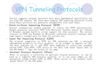
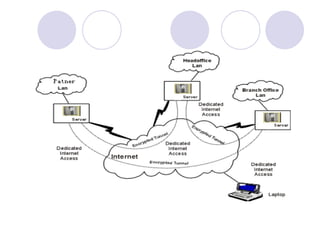
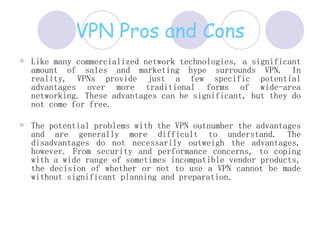
VPN  (virtual private network) presented by: Faisal Malik
Definition and Overview Definition An Internet-based virtual private network (VPN) uses the open, distributed infrastructure of the Internet to transmit data between corporate sites.  Overview This presentation addresses the basic architecture and enabling technologies of a VPN. The benefits and applications of VPNs are also explored.
VPN tunneling Virtual private network technology is based on the idea of tunneling.  VPN tunneling  involves establishing and maintaining a logical network connection (that may contain intermediate hops). On this connection, packets constructed in a specific VPN protocol format are encapsulated within some other base or carrier protocol, then transmitted between VPN client and server, and finally de-encapsulated on the receiving side.  For Internet-based VPNs, packets in one of several VPN protocols are encapsulated within Internet Protocol (IP) packets. VPN protocols also support authentication and encryption to keep the tunnels secure.
 
TYPES OF TUNNELING VPN supports two types of tunneling -  voluntary and compulsory . Both types of tunneling are commonly used.  In voluntary tunneling, the VPN client manages connection setup.  In compulsory tunneling, the carrier network provider manages VPN connection setup. When the client first makes an ordinary connection to the carrier, the carrier in turn immediately brokers a VPN connection between that client and a VPN server. From the client point of view, VPN connections are set up in just one step compared to the two-step procedure required for voluntary tunnels.  Compulsory VPN tunneling authenticates clients and associates them with specific VPN servers using logic built into the broker device. This network device is sometimes called the VPN Front End Processor (FEP), Network Access Server (NAS) or Point of Presence Server (POS). Compulsory tunneling hides the details of VPN server connectivity from the VPN clients and effectively transfers management control over the tunnels from clients to the ISP. In return, service providers must take on the additional burden of installing and maintaining FEP devices.
VPN Tunneling Protocols Several computer network protocols have been implemented specifically for use with VPN tunnels. The three most popular VPN tunneling protocols listed below.These protocols are generally incompatible with each other.  Point-to-Point Tunneling Protocol (PPTP)   Several corporations worked together to create the PPTP specification. People generally associate PPTP with Microsoft because nearly all flavors of Windows include built-in client support for this protocol. The initial releases of PPTP for Windows by Microsoft contained security features that some experts claimed were too weak for serious use.  Layer Two Tunneling Protocol (L2TP)   The original competitor to PPTP for VPN tunneling was L2F, a protocol implemented primarily in Cisco products. In an attempt to improve on L2F, the best features of it and PPTP were combined to create new standard called L2TP. Like PPTP, L2TP exists at the data link layer (Layer Two) in the OSI model -- thus the origin of its name.  Internet Protocol Security (IPsec)   IPsec is actually a collection of multiple related protocols. It can be used as a complete VPN protocol solution, or it can used simply as the encryption scheme within L2TP or PPTP. IPsec exists at the network layer (Layer Three) of the OSI model.
 
Inverse Multiplexing Inverse Multiplexing (or I Muxing) is exactly the opposite of traditional multiplexing. Instead of combining multiple streams of data into a single circuit, inverse multiplexing combines multiple circuits into a single logical data pipe. So, a large, single stream of data is split up and spread across multiple T1 circuits and then recombined into a single data stream at the other end. The data is spread across the T1 circuits in a round robin fashion, meaning that each bit of data is sequentially sent to the next T1 in a circular fashion.
T1, T2, T3 (American standards) and the E1, E2, E3, E4 (European standards)  E1 - 2.048 Mbit/Sec  E2 - 8.448 Mbit/Sec  E3 - 34.368 Mbit/Sec  E4 - 139.264 Mbit/Sec  The En is the result of multiplextion of  4 En-1.  T1 Link----- 1.544 Mbps T3 Link-----45 Mbps
SDH/SONET  G.703  -  Physical/Electrical Characteristics of Hierarchical Digital Interfaces Synchronous Digital Hierarchy (SDH) and Synchronous optical Network refers to a group of fiber optic transmission rate that can support digital signals with different capacities
SDH Frame Structure   The STM-n frame structure is best represented as a rectangle of   9 * 270 * N. The 9*N first columns are the frame header and the rest of the frame is the inner structure data (including the data, indication bits, stuff bits, pointers and management).    The STM-n frame is usually transmitted over an optical fiber. The frame is transmitted row by row (first is transmitted the first row then the second and so on). At the beginning of each frame a synchronized bytes A1A2 are transmitted .    The multiplexing method of 4 STM-n streams into a STM-nx4 is an interleaving of the STM-n streams to produce the STM-nx4 stream.
 
After interleaving we get a higher order stream that in its rectangular form all the low order STM streams are placed as its columns which makes it easier to find each of them in the bigger frame.
IP Address Scheme at Star   News       192.168.56.28 Receive2   255.255.255.0 Subnet mask  192.168.100.27 Receive1   192.168.56.27 Receive1   192.168.0.27 Receive  192.168.100.26 Transmit   192.168.56.26 Transmit   192.168.0.26 Tansmit  192.168.100.25 Router    192.168.56.25 Router    192.168.0.25 Router      Kolkata   Mumbai   Delhi
192.168.62.130 transmit   192.168.62.34 Transmit 192.168.62.129 Router    192.168.62.33 Router    Hosts/Net: 30      Hosts/Net: 30  192.168.62.158 HostMax:    192.168.62.62  HostMax:  192.168.62.129 HostMin:    192.168.62.33 HostMin:  192.168.62.159 Broadcast:    192.168.62.63  Broadcast:  192.168.62.128/27  Network:    192.168.62.32/27  Network:  255.255.255.224 = 27 Netmask:    255.255.255.224 = 27 Netmask:  192.168.62.128 Address:    192.168.62.32  Address:    Chandigarh   Bhopal 192.168.62.98 transmit   192.168.62.2 Transmit  192.168.62.97 Router    192.168.62.1 Router    Hosts/Net: 30    30 Hosts/Net:  192.168.62.126 HostMax:    192.168.62.30  HostMax:  192.168.62.97 HostMin:    192.168.62.1  HostMin:  192.168.62.127 Broadcast:    192.168.62.31  Broadcast:  192.168.62.96/27  Network:    192.168.62.0/27  Network:  255.255.255.224 = 27 Netmask:    255.255.255.224 = 27  Netmask:  192.168.62.96  Address:    192.168.62.0  Address:    Banglore   Ahemdabad
192.168.62.194 transmit     192.168.62.226 transmit 192.168.62.193 Router      192.168.62.225 Router    Hosts/Net: 30      Hosts/Net: 30   192.168.62.222 HostMax:    192.168.62.254 HostMax:            192.168.62.193 HostMin:      192.168.62.224 HostMin:            192.168.62.223 Broadcast:      192.168.62.255 Broadcast:         192.168.62.192/27  Network:    192.168.62.192/27  Network:         255.255.255.224 = 27 Netmask:    255.255.255.224 = 27 Netmask:      192.168.62.192 Address:    192.168.62.224 Address:             Guwahati   Siliguri 192.168.62.162 transmit   192.168.62.66 transmit 192.168.62.161 Router    192.168.62.65 Router    Hosts/Net: 30      Hosts/Net: 30  192.168.62.190 HostMax:    192.168.62.94 HostMax:  192.168.62.161 HostMin:    192.168.62.65 HostMin:  192.168.62.191 Broadcast:    192.168.62.95 Broadcast:  192.168.62.160/27  Network:    192.168.62.64/27  Network:  255.255.255.224 = 27 Netmask:    255.255.255.224 = 27 Netmask:  192.168.62.160 Address:    192.168.62.64  Address:    Patna   Lucknow
VPN Pros and Cons Like many commercialized network technologies, a significant amount of sales and marketing hype surrounds VPN. In reality, VPNs provide just a few specific potential advantages over more traditional forms of wide-area networking. These advantages can be significant, but they do not come for free.  The potential problems with the VPN outnumber the advantages and are generally more difficult to understand. The disadvantages do not necessarily outweigh the advantages, however. From security and performance concerns, to coping with a wide range of sometimes incompatible vendor products, the decision of whether or not to use a VPN cannot be made without significant planning and preparation .

Vpn Virtual Private Network

  • 1.
    VPN (virtualprivate network) presented by: Faisal Malik
  • 2.
    Definition and OverviewDefinition An Internet-based virtual private network (VPN) uses the open, distributed infrastructure of the Internet to transmit data between corporate sites. Overview This presentation addresses the basic architecture and enabling technologies of a VPN. The benefits and applications of VPNs are also explored.
  • 3.
    VPN tunneling Virtualprivate network technology is based on the idea of tunneling. VPN tunneling involves establishing and maintaining a logical network connection (that may contain intermediate hops). On this connection, packets constructed in a specific VPN protocol format are encapsulated within some other base or carrier protocol, then transmitted between VPN client and server, and finally de-encapsulated on the receiving side. For Internet-based VPNs, packets in one of several VPN protocols are encapsulated within Internet Protocol (IP) packets. VPN protocols also support authentication and encryption to keep the tunnels secure.
  • 4.
  • 5.
    TYPES OF TUNNELINGVPN supports two types of tunneling - voluntary and compulsory . Both types of tunneling are commonly used. In voluntary tunneling, the VPN client manages connection setup. In compulsory tunneling, the carrier network provider manages VPN connection setup. When the client first makes an ordinary connection to the carrier, the carrier in turn immediately brokers a VPN connection between that client and a VPN server. From the client point of view, VPN connections are set up in just one step compared to the two-step procedure required for voluntary tunnels. Compulsory VPN tunneling authenticates clients and associates them with specific VPN servers using logic built into the broker device. This network device is sometimes called the VPN Front End Processor (FEP), Network Access Server (NAS) or Point of Presence Server (POS). Compulsory tunneling hides the details of VPN server connectivity from the VPN clients and effectively transfers management control over the tunnels from clients to the ISP. In return, service providers must take on the additional burden of installing and maintaining FEP devices.
  • 6.
    VPN Tunneling ProtocolsSeveral computer network protocols have been implemented specifically for use with VPN tunnels. The three most popular VPN tunneling protocols listed below.These protocols are generally incompatible with each other. Point-to-Point Tunneling Protocol (PPTP) Several corporations worked together to create the PPTP specification. People generally associate PPTP with Microsoft because nearly all flavors of Windows include built-in client support for this protocol. The initial releases of PPTP for Windows by Microsoft contained security features that some experts claimed were too weak for serious use. Layer Two Tunneling Protocol (L2TP) The original competitor to PPTP for VPN tunneling was L2F, a protocol implemented primarily in Cisco products. In an attempt to improve on L2F, the best features of it and PPTP were combined to create new standard called L2TP. Like PPTP, L2TP exists at the data link layer (Layer Two) in the OSI model -- thus the origin of its name. Internet Protocol Security (IPsec) IPsec is actually a collection of multiple related protocols. It can be used as a complete VPN protocol solution, or it can used simply as the encryption scheme within L2TP or PPTP. IPsec exists at the network layer (Layer Three) of the OSI model.
  • 7.
  • 8.
    Inverse Multiplexing InverseMultiplexing (or I Muxing) is exactly the opposite of traditional multiplexing. Instead of combining multiple streams of data into a single circuit, inverse multiplexing combines multiple circuits into a single logical data pipe. So, a large, single stream of data is split up and spread across multiple T1 circuits and then recombined into a single data stream at the other end. The data is spread across the T1 circuits in a round robin fashion, meaning that each bit of data is sequentially sent to the next T1 in a circular fashion.
  • 9.
    T1, T2, T3(American standards) and the E1, E2, E3, E4 (European standards) E1 - 2.048 Mbit/Sec E2 - 8.448 Mbit/Sec E3 - 34.368 Mbit/Sec E4 - 139.264 Mbit/Sec The En is the result of multiplextion of 4 En-1. T1 Link----- 1.544 Mbps T3 Link-----45 Mbps
  • 10.
    SDH/SONET G.703 - Physical/Electrical Characteristics of Hierarchical Digital Interfaces Synchronous Digital Hierarchy (SDH) and Synchronous optical Network refers to a group of fiber optic transmission rate that can support digital signals with different capacities
  • 11.
    SDH Frame Structure The STM-n frame structure is best represented as a rectangle of  9 * 270 * N. The 9*N first columns are the frame header and the rest of the frame is the inner structure data (including the data, indication bits, stuff bits, pointers and management).   The STM-n frame is usually transmitted over an optical fiber. The frame is transmitted row by row (first is transmitted the first row then the second and so on). At the beginning of each frame a synchronized bytes A1A2 are transmitted .   The multiplexing method of 4 STM-n streams into a STM-nx4 is an interleaving of the STM-n streams to produce the STM-nx4 stream.
  • 12.
  • 13.
    After interleaving weget a higher order stream that in its rectangular form all the low order STM streams are placed as its columns which makes it easier to find each of them in the bigger frame.
  • 14.
    IP Address Schemeat Star News       192.168.56.28 Receive2   255.255.255.0 Subnet mask 192.168.100.27 Receive1   192.168.56.27 Receive1   192.168.0.27 Receive 192.168.100.26 Transmit   192.168.56.26 Transmit   192.168.0.26 Tansmit 192.168.100.25 Router   192.168.56.25 Router   192.168.0.25 Router     Kolkata   Mumbai   Delhi
  • 15.
    192.168.62.130 transmit  192.168.62.34 Transmit 192.168.62.129 Router   192.168.62.33 Router   Hosts/Net: 30     Hosts/Net: 30 192.168.62.158 HostMax:   192.168.62.62 HostMax: 192.168.62.129 HostMin:   192.168.62.33 HostMin: 192.168.62.159 Broadcast:   192.168.62.63 Broadcast: 192.168.62.128/27 Network:   192.168.62.32/27 Network: 255.255.255.224 = 27 Netmask:   255.255.255.224 = 27 Netmask: 192.168.62.128 Address:   192.168.62.32 Address:   Chandigarh   Bhopal 192.168.62.98 transmit   192.168.62.2 Transmit 192.168.62.97 Router   192.168.62.1 Router   Hosts/Net: 30   30 Hosts/Net: 192.168.62.126 HostMax:   192.168.62.30 HostMax: 192.168.62.97 HostMin:   192.168.62.1 HostMin: 192.168.62.127 Broadcast:   192.168.62.31 Broadcast: 192.168.62.96/27 Network:   192.168.62.0/27 Network: 255.255.255.224 = 27 Netmask:   255.255.255.224 = 27 Netmask: 192.168.62.96 Address:   192.168.62.0 Address:   Banglore   Ahemdabad
  • 16.
    192.168.62.194 transmit    192.168.62.226 transmit 192.168.62.193 Router     192.168.62.225 Router   Hosts/Net: 30     Hosts/Net: 30  192.168.62.222 HostMax:   192.168.62.254 HostMax:            192.168.62.193 HostMin:     192.168.62.224 HostMin:            192.168.62.223 Broadcast:     192.168.62.255 Broadcast:        192.168.62.192/27 Network:   192.168.62.192/27 Network:         255.255.255.224 = 27 Netmask:   255.255.255.224 = 27 Netmask:      192.168.62.192 Address:   192.168.62.224 Address:             Guwahati   Siliguri 192.168.62.162 transmit   192.168.62.66 transmit 192.168.62.161 Router   192.168.62.65 Router   Hosts/Net: 30     Hosts/Net: 30 192.168.62.190 HostMax:   192.168.62.94 HostMax: 192.168.62.161 HostMin:   192.168.62.65 HostMin: 192.168.62.191 Broadcast:   192.168.62.95 Broadcast: 192.168.62.160/27 Network:   192.168.62.64/27 Network: 255.255.255.224 = 27 Netmask:   255.255.255.224 = 27 Netmask: 192.168.62.160 Address:   192.168.62.64 Address:   Patna   Lucknow
  • 17.
    VPN Pros andCons Like many commercialized network technologies, a significant amount of sales and marketing hype surrounds VPN. In reality, VPNs provide just a few specific potential advantages over more traditional forms of wide-area networking. These advantages can be significant, but they do not come for free. The potential problems with the VPN outnumber the advantages and are generally more difficult to understand. The disadvantages do not necessarily outweigh the advantages, however. From security and performance concerns, to coping with a wide range of sometimes incompatible vendor products, the decision of whether or not to use a VPN cannot be made without significant planning and preparation .