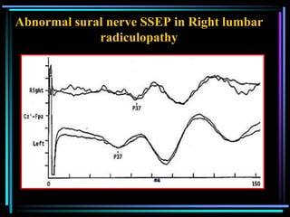
Downloaded 2,088 times


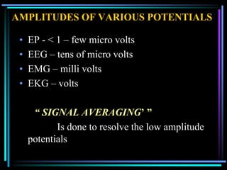
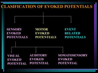
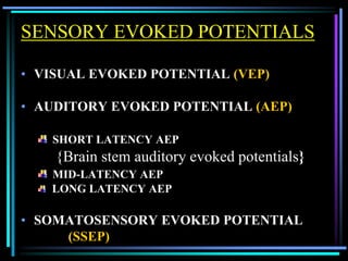
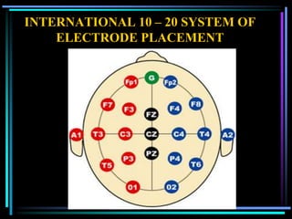


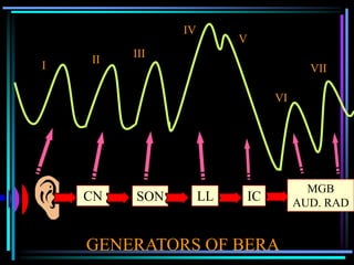


Evoked potentials are low amplitude electrical potentials recorded from the brain or peripheral nerves in response to sensory stimuli. They are used to evaluate the function of sensory and motor pathways. There are several types including sensory evoked potentials from visual, auditory and somatosensory stimulation as well as motor evoked potentials. Recording techniques involve signal averaging to detect the low amplitude signals. Evoked potentials provide objective measures for diagnosing various neurological disorders.


