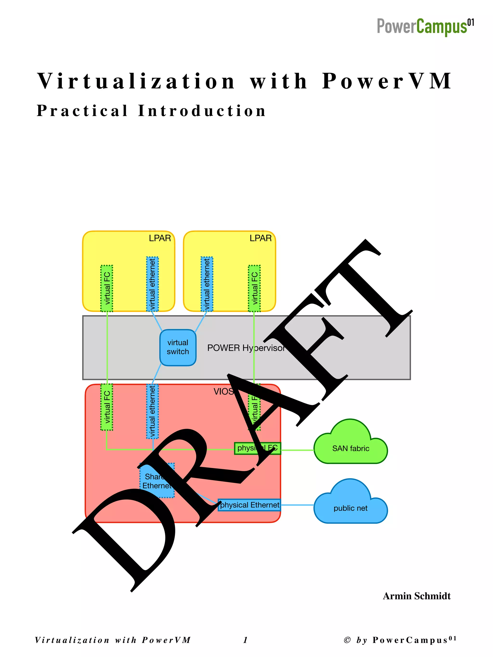
Vi r t u a l i z a t i o n w i t h P o w e r V M

1 © b y P o w e r C a m p u s 0 1
V i r t u a l i z a t i o n w i t h P o w e r V
M

P r a c t i c a l I n t r o d u c t i o n
LPAR
POWER Hypervisor
LPAR
virtual
switch
virtual
FC
virtual
FC
virtual
FC
virtual
FC
public net
SAN fabric
virtual
ethernet
virtual
ethernet
virtual
ethernet
VIOS
physical Ethernet
physical FC
Shared
Ethernet
D
R
A
F
T
Armin Schmidt
Copyright © 2021 by PowerCampus01
This manual is the intellectual property of PowerCampus01
.

It may be copied and also printed out as a whole or in parts, as long as no parts are changed
.

All information contained in this manual has been compiled with great care. However, incorrect information cannot
be completely ruled out. PowerCampus01 is not liable for any errors and their consequences. The content can be
changed at any time without notice
.

Software and hardware names in this manual are in many cases registered trademarks and are subject to the copyright
of the respective manufacturer
.

https://www.powercampus.de
https://www.powercampus01.com
First edition (June 2021
)

This version of the document refers to version 1.6.4.0 of the LPAR tool
.

Vi r t u a l i z a t i o n w i t h P o w e r V M

2 © b y P o w e r C a m p u s 0 1
Foreword
	
9


........................................................................................................
Introduction	 9


..............................................................................................................
Additional Information	 9


..............................................................................................
1. Introduction to IBM PowerVM
	
10


.................................................................
1.1. PowerVM Features	 10


........................................................................................
1.2. The POWER Hypervisor	 11


................................................................................
1.3. PowerVM Editions	 12


.........................................................................................
1.3.1. PowerVM Standard Edition	 12


....................................................................................................................................
1.3.2. PowerVM Enterprise Edition	 13


...................................................................................................................................
1.3.3. IBM PowerVM, Linux Edition	 13


..................................................................................................................................
1.3.4. PowerVM Express Edition	 14


.......................................................................................................................................
2. Introduction to the LPAR tool
	
15


...................................................................
2.1. Requirements	 16


................................................................................................
2.2. Downloading the LPAR tool	 16


...........................................................................
2.3. License for the LPAR tool	 16


...............................................................................
2.4. The Commands of the LPAR tool	 17


....................................................................
2.4.1. The Command hmc	 17


...............................................................................................................................................
2.4.2. The Command ms	 18


.................................................................................................................................................
2.4.3. The Command lpar	 19


...............................................................................................................................................
2.4.4. The Command vios	 21


...............................................................................................................................................
2.4.5. The Online Documentation	 23


....................................................................................................................................
2.4.6. The „verbose“ Mode	 25


.............................................................................................................................................
2.4.7. Logging of the Command Calls	 25


.............................................................................................................................
3. Components of a PowerVM Environment
	
27


................................................
3.1. Hardware Management Console (HMC)	 28


........................................................
3.2. Managed Systems	 30


........................................................................................
3.3. PowerVC	 31


......................................................................................................
4. Overview of a PowerVM Environment
	
32


....................................................
4.1. What LPARs are out there?	 32


............................................................................
4.2. Status of LPARs	 33


.............................................................................................
4.3. Activating an LPAR	 34


.......................................................................................
Vi r t u a l i z a t i o n w i t h P o w e r V M

3 © b y P o w e r C a m p u s 0 1
4.4. Shutting down an LPAR	 35


.................................................................................
4.5. Console for an LPAR	 36


.....................................................................................
4.6. Status of Managed Systems	 37


..........................................................................
4.7. System Firmware Version of Managed Systems	 37


...............................................
4.8. Physical Hardware of Managed Systems	 38


........................................................
5. Processor Virtualization
	
40


..........................................................................
5.1. Dedicated Processors	 40


....................................................................................
5.1.1. Adding Dedicated Processors	 42


.................................................................................................................................
5.1.2. Removing Dedicated Processors	 44


............................................................................................................................
5.2. Shared Processors (Micro-Partitioning)	 45


...........................................................
5.2.1. Processor Sharing Mode	 51


........................................................................................................................................
5.2.2. Sharing Mode cap	 52


.................................................................................................................................................
5.2.3. Sharing Mode uncap and uncapped_weight	 53


.........................................................................................................
5.2.4. Adding Virtual Processors and Processing Units	 56


.....................................................................................................
5.2.5. Removing Virtual Processors and Processing Units	 57


.................................................................................................
5.3. Processors, Processor Cores and Simultaneous Multi-Threading	 57


.......................
5.3.1. POWER Processors	 58


................................................................................................................................................
5.3.2. Simultaneous Multi-Threading	 58


..............................................................................................................................
5.4. Shared Dedicated Capacity	 59


..........................................................................
5.5. Multiple Shared Processor Pools	 61


....................................................................
5.5.1. Physical Shared Processor Pool	 62


.............................................................................................................................
5.5.2. Multiple Shared Processor Pools	 62


............................................................................................................................
5.5.3. Con
fi
guring a Shared Processor Pool (Maximum Pool Capacity)	 63


............................................................................
5.5.4. Assigning of a Shared Processor Pool	 64


....................................................................................................................
5.5.5. Entitled Pool Capacity (EPC)	 66


..................................................................................................................................
5.5.6. Reserved Pool Capacity (RPC)	 70


...............................................................................................................................
5.5.7. Deactivating a Shared Processor Pool	 71


....................................................................................................................
6. Memory Virtualization
	
72


............................................................................
6.1. Dedicated Memory	 72


......................................................................................
6.1.1. Adding Memory	 75


....................................................................................................................................................
6.1.2. Removing Memory	 76


................................................................................................................................................
Vi r t u a l i z a t i o n w i t h P o w e r V M

4 © b y P o w e r C a m p u s 0 1
6.2. Active Memory Sharing (AMS)	 77


.....................................................................
6.2.1. Creation of a Shared Memory Pool	 79


.......................................................................................................................
6.2.2. Adding a Paging Device	 80


........................................................................................................................................
6.2.3. Creation of LPARs with Shared Memory	 81


.................................................................................................................
6.2.4. Changing a Dedicated Memory LPAR to Shared Memory	 83


........................................................................................
6.2.5. Logical Memory and Paging	 84


.................................................................................................................................
6.2.6. Monitoring of the Logical Memory	 86


........................................................................................................................
6.2.7. Changing a Shared Memory Pool	 88


..........................................................................................................................
6.2.8. Switch-over of a Redundant Paging Device	 89


............................................................................................................
6.2.9. I/O Entitled Memory	 89


............................................................................................................................................
6.2.10. Removing a Paging Device	 90


....................................................................................................................................
6.2.11. Removing a Shared Memory Pool	 91


.........................................................................................................................
6.3. Active Memory Expansion (AME)	 92


..................................................................
6.3.1. Con
fi
guring AME	 93


...................................................................................................................................................
6.3.2. Active Memory Expansion Planning Tool (amepat)	 94


................................................................................................
6.3.3. Monitoring and Memory De
fi
cit	 95


............................................................................................................................
6.3.4. Changing the AME Factor	 97


......................................................................................................................................
6.3.5. Adding and Removing Memory	 97


.............................................................................................................................
6.3.6. Active Memory Expansion and Active Memory Sharing	 97


..........................................................................................
7. I/O Virtualization
	
98


....................................................................................
7.1. Virtual Slots	 99


.................................................................................................
7.2. Virtual Serial Adapter	 100


.................................................................................
7.2.1. Console using a Virtual I/O Server	 102


......................................................................................................................
7.3. Virtual Ethernet	 104


..........................................................................................
7.3.1. VLANs and VLAN Tagging	 105


....................................................................................................................................
7.3.2. Adding a Virtual Ethernet Adapter	 107


.......................................................................................................................
7.3.3. Virtual Ethernet Switches	 109


.....................................................................................................................................
7.3.4. Virtual Ethernet Bridge Mode (VEB)	 112


.....................................................................................................................
7.3.5. Virtual Ethernet Port Aggregator Mode (VEPA)	 112


.....................................................................................................
7.3.6. Virtual Networks	 113


.................................................................................................................................................
7.3.7. Adding and Removing VLANs to/from an Adapter	 115


................................................................................................
Vi r t u a l i z a t i o n w i t h P o w e r V M

5 © b y P o w e r C a m p u s 0 1
7.3.8. Changing Attributes of a Virtual Ethernet Adapter	 116


................................................................................................
7.3.9. Removing a Virtual Ethernet Adapter	 117


...................................................................................................................
7.4. Virtual FC	 118


...................................................................................................
7.4.1. NPIV-fähige FC-Adapter	 120


.......................................................................................................................................
7.4.2. Adding a Virtual FC Adapter	 121


................................................................................................................................
7.4.3. Assigning a Physical FC Port (Mapping)	 124


...............................................................................................................
7.4.4. Adding LUNs	 127


.......................................................................................................................................................
7.4.5. Adding a Virtual FC Adapter with Mapping	 128


..........................................................................................................
7.4.6. Changing Attributes of a Virtual FC Adapter	 128


.........................................................................................................
7.4.7. Removing an NPIV Mapping	 129


................................................................................................................................
7.4.8. Changing an NPIV Mapping	 130


.................................................................................................................................
7.4.9. Removing a Virtual FC Adapter	 133


............................................................................................................................
7.4.10. Assigning Prede
fi
ned WWPNs	 136


..............................................................................................................................
7.5. Virtual SCSI	 137


................................................................................................
7.5.1. Adding a Virtual SCSI Adapter	 138


.............................................................................................................................
7.5.2. Assignment of Virtual Target Devices (Mapping)	 141


..................................................................................................
7.5.3. Removing a VSCSI Mapping	 145


.................................................................................................................................
7.5.4. Removing a Virtual SCSI Adapter	 147


.........................................................................................................................
7.6. SR-IOV	 151


.......................................................................................................
7.6.1. Activating Shared Mode	 152


......................................................................................................................................
7.6.2. Con
fi
guration of Physical SR-IOV Ports	 153


.................................................................................................................
7.6.3. Adding Logical SR-IOV Ports	 155


.................................................................................................................................
7.6.4. Changing a Logical SR-IOV Port	 157


...........................................................................................................................
7.6.5. Removing Logical SR-IOV Ports	 158


............................................................................................................................
7.6.6. Setting an SR-IOV Adapter from Shared back to Dedicated	 158


...................................................................................
7.7. Virtual Network Interface Controller (vNIC)	 159


.................................................
7.7.1. Creating a vNIC Adapter	 160


......................................................................................................................................
7.7.2. Changing a vNIC Adapter	 163


....................................................................................................................................
7.7.3. Adding a vNIC Backing Device	 163


.............................................................................................................................
7.7.4. Changing a vNIC Backing Device	 165


.........................................................................................................................
7.7.5. vNIC Failover	 166


......................................................................................................................................................
Vi r t u a l i z a t i o n w i t h P o w e r V M

6 © b y P o w e r C a m p u s 0 1
7.7.6. Manual Activation of a vNIC Backing Device	 169


........................................................................................................
7.7.7. Removing a vNIC Backing Device	 169


.........................................................................................................................
7.7.8. Removing a vNIC Adapter	 171


....................................................................................................................................
8. Virtual I/O Server
	
172


..................................................................................
8.1. Planning and Creation of a Virtual I/O Server	 172


..............................................
8.2. Installation a Virtual I/O Server	 175


...................................................................
8.2.1. Installation using a CD or DVD	 175


............................................................................................................................
8.3. Device management	 186


...................................................................................
8.3.1. Viewing Available Devices	 187


...................................................................................................................................
8.3.2. Adding Devices	 190


...................................................................................................................................................
8.3.3. Changing Devices	 191


................................................................................................................................................
8.3.4. Removing Devices	 191


...............................................................................................................................................
8.4. Error Report	 192


...............................................................................................
8.5. Shared Ethernet Adapter	 194


.............................................................................
8.5.1. SEA without VLAN Tagging	 196


..................................................................................................................................
8.5.2. SEA with VLAN Tagging	 198


.......................................................................................................................................
8.5.3. Some SEA Attributes	 211


............................................................................................................................................
8.5.4. Con
fi
guring an IP Address on a SEA	 212


.....................................................................................................................
8.5.5. Adding and Removing VLANs (not HA)	 214


.................................................................................................................
8.5.6. Adding and Removing Trunking Adapters (not HA)	 215


..............................................................................................
8.5.7. Removing a Shared Ethernet Adapter (not HA)	 216


....................................................................................................
8.5.8. HA-SEA with Failover	 218


...........................................................................................................................................
8.5.9. Creating SEAs with HA Mode (HA-SEA)	 221


.................................................................................................................
8.5.10. HA-Modes auto and standby	 223


...............................................................................................................................
8.5.11. Adding and Removing VLANs (HA-SEA)	 224


................................................................................................................
8.5.12. Adding and Removing Trunking Adapters (HA-SEA)	 226


.............................................................................................
8.5.13. Removing HA-SEAs	 227


..............................................................................................................................................
8.5.14. HA-SEA with Load Sharing	 228


...................................................................................................................................
8.5.15. Creation of SEAs with Load Sharing	 229


.....................................................................................................................
8.5.16. Adding and Removing VLANs (Load Sharing)	 232


......................................................................................................
8.5.17. Adding and Removing Trunking Adapters (Load Sharing)	 234


....................................................................................
Vi r t u a l i z a t i o n w i t h P o w e r V M

7 © b y P o w e r C a m p u s 0 1
8.5.18. Change the HA Mode between Failover and Load Sharing	 236


....................................................................................
8.5.19. Deleting SEAs (Load Sharing)	 237


.............................................................................................................................
8.6. Storage Pools	 239


.............................................................................................
8.6.1. Creation of a Logical Volume Storage Pool	 241


...........................................................................................................
8.6.2. Creation of Backing Devices	 243


................................................................................................................................
8.6.3. Extending a Backing Device	 246


................................................................................................................................
8.6.4. Removing a Backing Device	 248


................................................................................................................................
8.6.5. Extending and Reducing a Logical Volume Storage Pool	 249


.......................................................................................
8.6.6. Deleting a Logical Volume Storage Pool	 251


...............................................................................................................
8.6.7. Creating a File Storage Pool	 253


................................................................................................................................
8.6.8. Extending a File Storage Pool	 254


.............................................................................................................................
8.6.9. Deleting a File Storage Pool	 254


................................................................................................................................
8.7. Virtual Optical Media Library	 255


.....................................................................
8.8. Link Aggregations	 259


.......................................................................................
9. Live Partition Mobility (LPM)
	
260
.................................................................
Vi r t u a l i z a t i o n w i t h P o w e r V M

8 © b y P o w e r C a m p u s 0 1
F o r e w o r
d

I n t r o d u c t i o
n

IBM PowerVM is a virtualization solution from IBM for IBM Power Systems. The LPAR tool is a command line
based tool from PowerCampus 01 for the simple administration of IBM PowerVM environments
.

The aim of the manual is to introduce and explain the virtualization concepts of IBM PowerVM, as well as to show
the con
fi
guration and administration of IBM PowerVM. The LPAR tool is used at all points, which means that the
manual can also serve as an introduction to the LPAR tool. The focus, however, is on PowerVM virtualization
.

Since this is an introduction to virtualization with PowerVM, the topics are not shown down to the last detail. The
IBM documentation should be consulted for more detailed information
.

The manual assumes the following
:

• basic knowledge of working on the command line of a UNIX syste
m

• a basic understanding of virtualization is helpful, but not require
d

This manual can be downloaded from the download area on the PowerCampus01 website
:

• https://www.powercampus.de or https://www.powercampus01.com
 

A d d i t i o n a l I n f o r m a t i o
n

Further information on the LPAR tool is available in the product area on the PowerCampus01 website
:

• https://www.powercampus.de oder https://www.powercampus01.com
More information about IBM PowerVM can be found on the IBM website
:

• https://www.ibm.com
Vi r t u a l i z a t i o n w i t h P o w e r V M

9 © b y P o w e r C a m p u s 0 1
1. I n t r o d u c t i o n t o I B M P o w e r V
M

IBM PowerVM is a virtualization solution from IBM especially for power systems. It consists of a combination of
special hardware and software. The main components of IBM PowerVM are as follows
:

- Special POWER hardware with
fi
rmware (POWER hypervisor), which enables the sharing of resources and other
features
.

- The virtual I/O server, as a special service partition, which enables the sharing of disk and network resources. For
increased redundancy, several virtual I/O servers can be con
fi
gured on one POWER system
.

The guest systems created by PowerVM are often referred to as LPARs (Logical PARtition). Recently, however, the
term VM (virtual machine) has also been used frequently here. We have retained the term LPAR instead of VM
throughout this document. AIX, IBM i and Linux can be used as guest operating systems, whereby Linux is then a
POWER-based Linux
.

1.1. P o w e r V M F e a t u r e
s

Below are some of the technologies and features of PowerVM
.

PowerVM Hypervisor (PHYP): This functionality is made available by the hardware platform in combination with
system
fi
rmware for the POWER server. The hypervisor is ultimately the basis for any virtualization on a POWER
system
.

Logical Partition (LPAR): LPARs are provided through the hypervisor. Originally, only dedicated hardware
components and complete processors could be allocated to an LPAR; only the memory was shared. In the course of
the Power Systems generations, the possibilities have been expanded further and further (micro-partition, dynamic
logical partition), although the term LPAR has been retained
.

Micro Partition: The micro partition allows a processor to be shared between different partitions. The micro
partitions are assigned parts of a processor, which is also referred to as shared processor partitions
.

Dynamic Logical Partition (DLPAR): Virtual resources (CPU, memory, physical adapters and virtual adapters) can
be added to or removed from the partition at runtime (provided that the operating system supports it). This means that
resources can be dynamically adapted to the needs of a partition
.

Shared Prozessor Pools (SPP): Partitions can be assigned to shared processor pools, so that the consumption of
processor resources by partitions can be limited to the resources available in the pool
.

Virtual I/O Server (VIOS): This is a special service partition with an AIX-based, specially extended operating
system for supporting a range of virtualization functions. Network adapters (Virtual Ethernet) and I/O adapters
(Virtual SCSI and Virtual FC) can be virtualized via virtual I/O servers
.

Virtual Ethernet (VETH): Client partitions can communicate in the network with the help of virtual Ethernet
adapters without having their own physical Ethernet adapters
.

Vi r t u a l i z a t i o n w i t h P o w e r V M

1 0 © b y P o w e r C a m p u s 0 1
Virtual SCSI (VSCSI): With the help of the virtual I/O server, client partitions can access disks via a virtual SCSI
adapter without having their own physical I/O adapter. The necessary physical adapters belong to the virtual I/O
servers and can therefore be shared by many partitions. The disks must be assigned to the virtual SCSI adapters
.

Virtual FC (VFC): In contrast to Virtual SCSI, Virtual FC allows a virtual FC adapter to be assigned directly to a
physical FC adapter. Unlike with VSCSI, the individual disks no longer have to be assigned to the virtual adapters,
which makes administration much easier
.

Live Partition Mobility (LPM): This feature allows an active partition to be moved online from one power system
to another power system. All applications and the operating system simply continue to run during the online move.
From the point of view of the applications, the move is transparent
.

Active Memory Expansion (AME): By compressing main memory, additional available main memory can be
obtained. The desired compression can be speci
fi
ed. With this, for example, from 32 GB of physical main memory
and a compression factor (AME factor) of 1.5, 48 GB of main memory can be obtained for one partition. The
operating system and all applications see 48 GB of available main memory
.

Single Root I/O Virtualization (SR-IOV): With this type of virtualization, a virtual I/O server is no longer required.
The virtualization takes place in hardware directly on the physical adapter. With PowerVM this is currently limited to
SR-IOV capable network adapters. The bandwidth of the SR-IOV Ethernet ports can be divided between the
individual partitions
.

Virtual Network Interface Controller (vNIC): Allows automatic failover to another SR-IOV Ethernet port if one
SR-IOV Ethernet port fails. For this, however, the support of virtual I/O servers is required again
.

Some other features of PowerVM were not included in this overview
.

1.2. T h e P O W E R H y p e r v i s o
r

Most virtualization functions are only possible through the POWER hypervisor. The hypervisor offers the possibility
of dividing physical resources and making them available to the partitions. The hypervisor ensures that each partition
has only access to its own resources, it isolates the individual partitions from each other. Each of the partitions can
use its own instance of an operating system; the supported operating systems are AIX, IBM i and Linux, or virtual I/
O servers
.

Figure 1.1 shows the virtualization using a hypervisor. The hardware layer, with all physical resources such as CPUs,
memory and physical slots, is below the hypervisor. Partitions do not have direct access to the hardware layer. Access
is only possible via the hypervisor. The hypervisor can assign dedicated resources for exclusive use by an LPAR, e.g.
dedicated CPUs or physical slots or physical memory areas, but depending on the type of resource it can also allow
shared use by several LPARs, e.g. shared processors or active memory sharing. In the case of shared processors, an
LPAR only gets a speci
fi
ed share of a processor, it can then only use the processor temporarily. The distribution to the
various LPARs is carried out by the hypervisor in a time slice process
.

Vi r t u a l i z a t i o n w i t h P o w e r V M

11 © b y P o w e r C a m p u s 0 1
No special processor resources are assigned to the POWER Hypervisor. LPARs communicate with the POWER
hypervisor via hypervisor calls (hcalls). Under AIX, this can be monitored more closely with the lparstat command
(option “-h” or “-H”)
.

1.3. P o w e r V M E d i t i o n
s

There are 3 different editions of PowerVM. These differ in the scope of the supported virtualization functions
.

1.3.1. P o w e r V M S t a n d a r d E d i t i o
n

PowerVM Standard Edition supports the following features
:

• micro partitionin
g

• virtual I/O server (VIOS
)

• Shared Processor Pool
s

• N-Port ID Virtualization (NPIV
)

• Shared Storage Pool
s

• Single Root I/O Virtualization (SR-IOV
)

POWER Hypervisor
CPU
I/O Slot
I/O Slot
Mem
Mem
LPAR
CPU CPU
I/O Slot
I/O Slot
Mem
LPAR
CPU
Hardware Resources
CPU CPU CPU CPU
I/O Slot
I/O Slot
I/O Slot
I/O Slot
I/O Slot
I/O Slot
Mem
Mem
Mem
Mem
Mem
Mem
Figure 1.1: PowerVM environment
Vi r t u a l i z a t i o n w i t h P o w e r V M

1 2 © b y P o w e r C a m p u s 0 1
• virtual Network Interface Controller adapter (vNIC
)

• thin provisionin
g

• suspend and resume on POWER8 (or higher) system
s

• PowerVM NovaLin
k

1.3.2. P o w e r V M E n t e r p r i s e E d i t i o
n

The PowerVM Enterprise Edition supports the following features
:

• Live Partition Mobility (LPM
)

• Active Memory Sharing (AMS
)

• Remote Restar
t

• Power Virtualization Performance (PowerVP
)

• micro partitionin
g

• virtual I/O server (VIOS
)

• Shared Processor Pool
s

• N-Port ID Virtualization (NPIV
)

• Shared Storage Pool
s

• Single Root I/O Virtualization (SR-IOV
)

• virtual Network Interface Controller adapter (vNIC
)

• thin provisionin
g

• suspend and resume on POWER8 (or higher) system
s

• PowerVM NovaLin
k

1.3.3. I B M P o w e r V M , L i n u x E d i t i o
n

PowerVM Standard Edition supports the following features
:

• Active Memory Sharing (AMS
)

• Live Partition Mobility (LPM
)

• Remote Restar
t

• Power Virtualization Performance (PowerVP
)

• micro partitionin
g

• virtual I/O server (VIOS
)

• Shared Processor Pool
s

• N-Port ID Virtualization (NPIV
)

• Shared Storage Pool
s

• Single Root I/O Virtualization (SR-IOV
)

Vi r t u a l i z a t i o n w i t h P o w e r V M

1 3 © b y P o w e r C a m p u s 0 1
• virtual Network Interface Controller adapter (vNIC
)

• thin provisionin
g

• suspend and resume on POWER8 (or higher) system
s

• PowerVM NovaLin
k

1.3.4. P o w e r V M E x p r e s s E d i t i o
n

The previously offered PowerVM Express Edition with a minimal number of features is no longer offered
.

Vi r t u a l i z a t i o n w i t h P o w e r V M

1 4 © b y P o w e r C a m p u s 0 1
2. I n t r o d u c t i o n t o t h e L PA R t o o l
The LPAR tool is a command line based tool for the simple administration of PowerVM environments. PowerVM
environments of any size with multiple HMCs and any number of managed systems can be managed. The LPAR tool
was developed with the following objectives
:

- Ease of use: The LPAR tool should be easy and intuitive to use. Sensible defaults are stored for all commands so
that not every detail has to be speci
fi
ed on the command line. This means that even a less experienced user should
be able to administer PowerVM without any problems
.

- High speed: Most commands take less than a second to execute. This means there is no annoying lengthy wait for
a command to be completed
.

- Online documentation: All functions of the LPAR tool are documented online. Nothing is more annoying in day-to-
day work than constantly looking up information in external documentation. (Of course, there is still a detailed
documentation in case the online documentation should not be suf
fi
cient.
)

- Feature for the PowerVM expert: With the LPAR tool, the expert can dive into the depths of PowerVM
.

- Selectable output format: When printing information, in addition to the standard output, output in JSON, YAML or
Stanza format can also be selected
.

- Use in scripts: The use in scripts for the automation of processes is very easy
.

The LPAR tool can be installed on one or more systems. Since the LPAR tool uses OpenSSH to communicate with the
HMCs, an SSH connection to the HMCs must be possible from these systems. The LPAR tool is available for the
following operating systems
:

- AI
X

- Linux x8
6

- MacO
S

The following manuals are available from the download area https://powercampus.de/download
:

• LPAR-Tool 1.6.0.x What’s New (PDF
)

• LPAR-Tool 1.6.0.x Getting Started (PDF
)

• LPAR-Tool 1.6.0.x User Guide (PDF
)

Vi r t u a l i z a t i o n w i t h P o w e r V M

1 5 © b y P o w e r C a m p u s 0 1
2.1. R e q u i r e m e n t
s

The LPAR tool uses OpenSSH to connect to the HMCs, i.e. a working version of OpenSSH must be installed on the
target system
.

In order that PowerVM can be administered with the LPAR tool, the HMCs to be administered must be accessible
from the target system via OpenSSH. This means that if a
fi
rewall is used between the target system and the HMC,
OpenSSH must be enabled from the target system to the HMC
.

To use the LPAR tool, a valid account on the HMC is required. If desired, the hscroot account can also be used.
However, the recommendation is that all users should use their own HMC account
.

If DLPAR operations or Live Partition Mobility are to be used, the LPARs must have an active RMC connection to
the HMCs. Without this requirement, PowerVM cannot perform these operations (this is a limitation of PowerVM)
.

2.2. D o w n l o a d i n g t h e L PA R t o o l
The LPAR tool can be downloaded from the download area of the website https://powercampus.de or https://
powercampus01.com. Depending on the operating system, there are one or two versions of the LPAR tool
.

AIX: For the AIX operating system, the LPAR tool can be downloaded either as a tar
fi
le or as a BFF
fi
leset. If you
don't want to install the LPAR tool permanently, but only want to try it out once, it is advisable to download the
version as a tar
fi
le. This can be unpacked at any place (e.g. in your own home directory)
.

Linux (x86): For Linux there is also a version as a tar
fi
le and an RPM package. Here, too, we recommend using the
tar
fi
le for a test installation
.

MacOS: For the Mac there is currently only one version as a tar
fi
le that can be extracted at any location
.

If the BFF
fi
leset or the RPM package is installed, the LPAR tool can be found in the /opt/pwrcmps/bin directory on
the target system
.

2.3. L i c e n s e f o r t h e L PA R t o o l
As a commercial product, the LPAR tool requires a license that must be entered in a
fi
le on the target system (/opt/
pwrcmps/etc/lpar.lic or ~/.lpar.lic). The LPAR tool may not be used productively without a valid subscription
(contains a license)
.

The LPAR tool can also be used for test and evaluation purposes without a valid subscription. To make this as easy as
possible, the latest version contains a time-limited test license. This means that the software can be tried out
immediately after the download and installation without having to request a license. The integrated test license has a
limited validity of usually 2 months from the build date of the version. On the download page it is noted until when
the integrated test license is valid
.

Vi r t u a l i z a t i o n w i t h P o w e r V M

1 6 © b y P o w e r C a m p u s 0 1
The integrated test license supports up to 10 HMCs, up to 100 managed systems and up to 1000 LPARs
.

For more extensive tests, it is possible to request a trial license
.

2.4. T h e C o m m a n d s o f t h e L PA R t o o l
The LPAR tool contains 4 commands, which are named after the components of a PowerVM environment: hmc, ms,
lpar and vios. Each of these 4 commands supports a variety of functions, more than 200 in total. This covers all areas
of PowerVM administration
.

2.4.1. T h e C o m m a n d h m c
The available HMCs can be managed with the hmc command. The administration of users on the HMCs as well as
the administration of roles (task and resource roles) are covered. In addition, a large amount of information from the
HMCs can be displayed. A complete list of the functions can be obtained by starting the command without
arguments
:

$ hm
c

USAGE
:

hmc [<option> ...] <keyword> [<option> ...] [<argument> ...
]

hmc -L|-
V

Recognized keywords
:

add - Register HMC(s) with LPAR too
l

addauthkeys - Add an authorized SSH ke
y

chhmcfs - Free space in HMC file system
s

chhmcusr - Change attributes of HMC user accoun
t

chresourcerole - Change managed resource rol
e

chtaskrole - Change managed task rol
e

chsvcevent - Update serviceable event on HM
C

cmd - Execute command on HM
C

connections - Display state of ssh master connection
s

disconnect - Exit a ssh master connectio
n

flrt - Show FLRT repor
t

history - Show state or configuration change
s

list - List names of specified HMC(s
)

lsauthkeys - List authorized SSH key
s

lshmcfs - List HMC file system informatio
n

lshmcusr - Show HMC user account
s

lslic - List LIC levels available in hard disk repositor
y

lslogon - Show logon informations for HM
C

lslparmigr - List partiton mobility capabilitie
s

lsnet - Display HMC network configuratio
n

lsresource - Show all managed resource objects on the specified HM
C

lsresourcerole - Show managed resource roles on the specified HM
C

lssvcevents - Displays console or serviceable event
s

lssysconn - List all systems connected to the specified HM
C

lstaskrole - Show managed task roles on the specified HM
C

mkhmcusr - Create HMC user accoun
t

mkresourcerole - Create managed resource rol
e

mktaskrole - Create managed task rol
e

passwd - Change passwor
d

remove - Unregister HMC(s) from LPAR too
l

Vi r t u a l i z a t i o n w i t h P o w e r V M

1 7 © b y P o w e r C a m p u s 0 1
rescan - Rereads cached informations from HMC(s
)

rmauthkeys - Remove an authorized SSH ke
y

rmhmcusr - Remove HMC user accoun
t

rmresourcerole - Remove managed resource rol
e

rmtaskrole - Remove managed task rol
e

show - Show specified HMC(s
)

shutdown - Shut down or reboo
t

termtask - Terminate a tas
k

version - Shows the HMC software versio
n

help [{<category>|<keyword>|usage}
]

$
 

2.4.2. T h e C o m m a n d m s
The command ms (managed system) allows the administration of managed systems. Among other things, the
following areas of administration are covered
:

- Management of virtual networks and switche
s

- Administration of SR-IO
V

- Entering update access keys (UAK
)

- Status of managed system
s

- Power-on and power-off of managed system
s

- Dynamic Plattform Optimisatio
n

- Pro
fi
le backup
s

- View processor, memory, and I/O informatio
n

-
…

A complete list of the supported functions is displayed if the ms command is started without arguments
:

$ m
s

USAGE
:

ms [<option> ...] <keyword> [<option> ...] [<argument> ...
]

ms -L|-
V

Recognized keywords
:

addvnetwork - Add virtual networ
k

addvswitch - Add virtual switc
h

bkprofdata - Back up profile dat
a

chattr - Change attribute
s

cheth - Changes virtual ethernet attributes of a managed syste
m

chled - Change state of an LE
D

chlparmigr - Changes partition migration attributes of managed syste
m

chlparutil - Change sample rate for utilization data collectio
n

chmem - Change memory attribute
s

chprocpool - Change shared processor pool attribute
s

chsriov - Switch SR-IOV adapter either to dedicated or shared mod
e

flrt - List FLR
T

Vi r t u a l i z a t i o n w i t h P o w e r V M

1 8 © b y P o w e r C a m p u s 0 1
chvnetwork - Change attributes of a virtual networ
k

chvswitch - Change attributes of a virtual switc
h

enteruak - Enter new Update Access Key (UAC
)

history - Show state or configuration change
s

initprofdata - Initialize profile dat
a

list - Show names for specified managed system
s

lsattr - List attribute
s

lseth - Display virtual ethernet attributes of managed syste
m

lsfc - List virtual FC information
s

lsled - Display state of system attention LED
s

lslic - List LIC level
s

lslparmigr - Display partition migration attributes of managed syste
m

lslparutil - Show sample rate for utilization data collectio
n

lsmem - Display informations about memor
y

lsmemopt - Show memory affinity score
s

lsproc - Show processing resource
s

lsprocpool - Show shared processor pool
s

lsprofdata - Lists profile data backup
s

lspwrmgmt - Show power management setting
s

lsrefcode - List reference codes for a service processo
r

lsslot - List physical I/O slot
s

lssriov - List informations for SR-IOV adapters, physical ports or logical port
s

lssysprof - List system profile
s

lsunit - List physical I/O unit
s

lsvnetwork - List virtual network
s

lsvswitch - List virtual switche
s

mksysprof - Create system profil
e

procstat - Show physical processor pool utilization dat
a

poweroff - Power off managed syste
m

poweron - Power on managed syste
m

rename - Rename managed syste
m

rmprofdata - Remove profile data backu
p

rmsysprof - Remove system profil
e

rmvnetwork - Remove virtual networ
k

rmvswitch - Remove virtual switc
h

rstprofdata - Restore profile dat
a

show - Show basic information
s

startmemopt - Start DPO or mirrored memory defragmentatio
n

stopmemopt - Stop DPO or mirrored memory defragmentatio
n

status - Display status of managed syste
m

help [{<category>|<keyword>|usage}
]

$
 

2.4.3. T h e C o m m a n d l p a r
All PowerVM functions that affect an LPAR can be carried out with the lpar command. The LPAR tool covers the
following areas of LPAR administration, among others
:

- Activate and deactivate of LPAR
s

- Access to the console of an LPA
R

- Administration of virtual adapters (serial, Ethernet, FC, SCSI, SR-IOV, vNIC
)

- Administration of memory and processor
s

- Creation and deletion of LPAR
s

Vi r t u a l i z a t i o n w i t h P o w e r V M

1 9 © b y P o w e r C a m p u s 0 1
- View performance dat
a

- Live Partition Mobility (validation and migration
)

- Manage partition pro
fi
le
s

-
…

An overview of the available functions is displayed when the lpar command is started without arguments
:

$ lpa
r

USAGE
:

lpar [<option> ...] <keyword> [<option> ...] [<argument> ...
]

lpar -L|-
V

Recognized keywords
:

activate - Activate AIX, Linux, IBM i or virtual I/O server partitio
n

actvnicbkdev - Make virtual NIC backing device activ
e

addeth - Add virtual ethernet adapte
r

addfc - Add virtual FC client adapte
r

addmem - Add memor
y

addprocs - Add dedicated or shared processor
s

addprocunits - Add processing unit
s

addscsi - Add virtual SCSI client adapte
r

addserial - Add virtual serial adapte
r

addslot - Add physical I/O slo
t

addsriov - Add SR-IOV logical por
t

addvlan - Add VLAN to virtual ethernet adapte
r

addvnic - Add vNIC adapte
r

addvnicbkdev - Add a backing device to a virtual NIC adapter of an LPA
R

applyprof - Apply partition profil
e

backup - Create backu
p

chattr - Change attribute
s

cheth - Change attributes of virtual ethernet adapte
r

chfc - Change virtual FC adapte
r

chled - Change state of LE
D

chmem - Change memory attribute
s

chproc - Change processor attribute
s

chprocpool - Change shared processor poo
l

chscsi - Change virtual SCSI adapte
r

chserial - Change virtual serial adapte
r

chsriov - Change attributes of SR-IOV logical por
t

chvnic - Change a vNIC adapter assigned to an LPAR
.

chvnicbkdev - Change attributes of a backing device for a virtual NI
C

clearvnicbkdev - Clear virtual NIC backing device erro
r

clone - Create clon
e

console - Open virtual console session for AIX, Linux or virtual I/O server partitio
n

create - Create AIX, Linux, IBM i or virtual I/O server partitio
n

delete - Remove partitio
n

disableeth - Disable virtual ethernet adapte
r

display - Display detailed information
s

dumprestart - Dump and restart a partitio
n

enableeth - Enable virtual ethernet adapte
r

flrt - List FLR
T

history - Show state or configuration change
s

list - Show names of specific LPAR
s

lsattr - List partition or profile attribute
s

lseth - Show virtual ethernet adapter
s

lsfc - Show virtual FC adapter
s

lsled - Display state of system attention LE
D

lslparmigr - List partition migration informatio
n

lsmem - Show memor
y

Vi r t u a l i z a t i o n w i t h P o w e r V M

2 0 © b y P o w e r C a m p u s 0 1
lsmemopt - Show DPO memory affinity score
s

lsproc - Show processing resource
s

lsprof - List partition profile
s

lsrefcode - List reference codes for an LPA
R

lsscsi - Show virtual SCSI adapter
s

lsserial - Show virtual serial adapter
s

lsslot - Show physical I/O slot
s

lssriov - Show SR-IOV logical port
s

lsvnic - Show vNIC adapter
s

lsvslot - Show virtual slot
s

migrate - Perform partition migratio
n

mkblueprint - Create blueprin
t

osshutdown - Issue OS shutdown command to shut down a partitio
n

procstat - Show utilization dat
a

rename - Rename LPA
R

rmconsole - Close virtual console session for AIX, Linux or virtual I/O server partitio
n

rmeth - Remove virtual ethernet adapte
r

rmfc - Remove virtual FC client adapte
r

rmmem - Remove memor
y

rmprocs - Remove dedicated or shared processor
s

rmprocunits - Remove processing unit
s

rmprof - Remove partition profil
e

rmscsi - Remove virtual SCSI client adapte
r

rmserial - Remove virtual serial adapte
r

rmslot - Remove physical I/O slo
t

rmsriov - Remove SR-IOV logical por
t

rmvlan - Remove VLAN from virtual ethernet adapte
r

rmvnic - Remove a vNIC adapter from an LPAR
.

rmvnicbkdev - Removes a backing device from a virtual NIC adapter of an LPA
R

savecurrcfg - Save current configuration of an LPAR to profil
e

show - Show basic information
s

shutdown - Shutdown AIX, Linux, IBM i or virtual I/O server partitio
n

status - Display current statu
s

stopmigr - Stop partition migratio
n

validate - Perform partition migration validatio
n

help [{<category>|<keyword>|usage}
]

$
 

2.4.4. T h e C o m m a n d v i o s
The virtualization functions of the virtual I/O server can be administered with the vios (virtual I/O server) command.
A direct login on the virtual I/O servers is not required. An active RMC connection between the virtual I/O server and
the associated HMCs is suf
fi
cient
.

In particular, the following PowerVM functionalities of a virtual I/O server can be administered
:

- Shared Ethernet Adapter (SEA
)

- NPIV mapping
s

- SCSI mapping
s

- Virtual Optical Media Repositor
y

- Storage Pool
s

Vi r t u a l i z a t i o n w i t h P o w e r V M

2 1 © b y P o w e r C a m p u s 0 1
- Link Aggregation
s

- Device management (display and setting of attributes
)

Here, too, you can get a complete overview of the supported functions by starting the vios command without
arguments
:

$ vio
s

USAGE
:

vios [<option> ...] <keyword> [<option> ...] [<argument> ...
]

vios -L|-
V

Recognized keywords
:

addfc - Add virtual FC server adapte
r

addlnaggadapter - Add adapter to Link Aggregatio
n

addscsi - Add virtual SCSI server adapte
r

addsppv - Add physical volume to storage poo
l

cfgdev - Configures devices in the Virtual I/O Serve
r

chdev - Changes the characteristics of a devic
e

chkdev - Check devices for virtual device provisioning capabilit
y

chlnagg - Change Link Aggregation attribute
s

chmedia - Change virtual optical medi
a

chrep - Change Virtual Media Repositor
y

chbdsp - Change attributes of backing devic
e

chsp - Change storage poo
l

cmd - Execute ioscli comman
d

errlog - Display error lo
g

fcstat - Show FC statistic
s

failoverlnagg - Failover Link Aggregatio
n

ioslevel - Display the Virtual I/O Server leve
l

list - Show names of specific virtual I/O server
s

loadopt - Load virtual optical media into virtual optical devic
e

lsattr - Show device attribute
s

lsbdsp - Show backing device
s

lsdev - Show device
s

lslnagg - Show Link Aggregation adapter
s

lsmedia - Show virtual optical medi
a

lsnpiv - Show NPIV mapping
s

lsnports - List available NPIV capable port
s

lspv - Display physical volume(s
)

lsrep - Show Virtual Media Repositor
y

lssea - Show shared Ethernet adapter
s

lssp - Show storage poo
l

lstcpip - Display TCP/IP settings and parameter
s

lsvopt - Show virtual optical device
s

lsvscsi - Show VSCSI mapping
s

map - Map backing device to virtual SCSI server adapte
r

mkbdsp - Create and/or map backing device from storage poo
l

mklnagg - Create Link Aggregation adapte
r

mkmedia - Create virtual optical media dis
k

mkrep - Create Virtual Media Repositor
y

mksea - Create Shared Ethernet Adapte
r

mksp - Create storage poo
l

mkvopt - Create virtual optical devic
e

rmbdsp - Remove backing devic
e

rmdev - Remove device from the syste
m

rmfc - Remove virtual FC server adapte
r

rmlnagg - Remove Link Aggregation adapte
r

rmlnaggadapter - Remove adapter from Link Aggregatio
n

rmmedia - Remove virtual optical medi
a

rmrep - Remove Virtual Media Repositor
y

rmscsi - Remove virtual SCSI server adapte
r

rmsea - Remove shared Ethernet adapte
r

Vi r t u a l i z a t i o n w i t h P o w e r V M

2 2 © b y P o w e r C a m p u s 0 1
rmsp - Remove file storage poo
l

rmsppv - Remove physical volume from storage poo
l

rmvopt - Remove virtual optical devic
e

seastat - Show or clear SEA client statistic
s

show - Show basic information
s

unloadopt - Remove virtual optical media from virtual optical devic
e

unmap - Unmap backing device from virtual SCSI server adapte
r

vfcmap - Map virtual FC adapter to physical FC por
t

vfcunmap - Unmap virtual FC adapter from physical FC por
t

help [{<category>|<keyword>|usage}
]

$
 

2.4.5. T h e O n l i n e D o c u m e n t a t i o
n

All 4 commands offer a detailed online help. All functions are organized in categories, such as SCSI, SEA, memory,
etc. Which categories are available for one of the 4 commands can be shown by using the argument (keyword)
"help", e.g.
:

$ lpar help
Help is available for the following categories
:

lpar help blueprint eth fc io led lic lp
m

lpar help mem memory power proc processor prof profil
e

lpar help scsi serial sriov vni
c

Specific help is available for each of the supported keywords
:

lpar help <keyword
>

For a complete list of all keywords try
:

lpar help usag
e

$
 

All functions (keywords) that belong to a category can be displayed by specifying one of the available categories
after the keyword "help", here e.g. the category "mem" with the command lpar
:

$ lpar help me
m

USAGE: lpar [<option> ...] <keyword> [<option> ...] [<argument> ...
]

Recognized keywords for topic 'mem' are
:

[-h <hmc>] [-m <ms>] [-p <profile>] addmem [-d] [-f] [-l <detail_level>] [-w
<wait_time>] [-v] <lpar> <mem>[k|K|m|M|g|G|t|T
]

[-h <hmc>] [-m <ms>] [-p <profile>] chmem [-d] [-f] [-l <detail_level>] [-w <wait_time>]
[-v] <lpar> <attributes> ..
.

[-h <hmc>] [-m <ms>] [-p <profile>|-H] lsmem [{-o <format>|-f|-j|-y}] [-F <fields>] [-s
<selections>] [-v] [<lpar> ...
]

[-h <hmc>] [-m <ms>] [-p <profile>] lsmemopt [{-o <format>|-f|-j|-y}] [-F <fields>] [-s
<selections>] [-v] [<lpar> ...
]

[-h <hmc>] [-m <ms>] [-p <profile>] rmmem [-d] [-f] [-l <detail_level>] [-w <wait_time>]
[-v] <lpar> <mem>[k|K|m|M|g|G|t|T
]

$
 

Detailed information on a speci
fi
c function (keyword) can be obtained through "help" and the speci
fi
cation of the
keyword, here e.g. for the keyword "chmem"
:

$ lpar help chme
m

USAGE
:

Vi r t u a l i z a t i o n w i t h P o w e r V M

2 3 © b y P o w e r C a m p u s 0 1
lpar [-h <hmc>] [-m <ms>] [-p <profile>] chmem [-d] [-f] [-l <detail_level>] [-w
<wait_time>] [-v] <lpar> <attributes> ..
.

DESCRIPTIO
N

Change memory attributes for an LPAR. If no option '-d' or '-p' i
s

specified, the command tries to change the attributes by a DLPA
R

operation and by changing the current profile
.

Since most of the attributes are either valid only for DLPAR o
r

the profile, but not both, this makes changing memory related attribute
s

somewhat complicated. To ease usage, the following filtering is applied
:

- If a specified attribute can not be changed by a DLPAR operation, th
e

attribute is skipped from the DLPAR operation
.

- If a specified attribute can not be changed in a profile, the attribut
e

is skipped from the operation
.

When skipping attibutes, a hint is shown to the user
!

-d : only DLPAR operation, don't update profil
e

-f : force operation, even if there is no RMC connectio
n

-l : level of detail (1-4
)

-p : update the specified profile onl
y

-w : time (minutes) to wait for operation to finis
h

valid attributes for DLPAR and profile
:

mem_weigh
t

mem_expansio
n

0 - disable memory expansion (profile only
)

1.00 to 10.00 - memory expansion facto
r

valid attributes for DLPAR only
:

hardware_mem_encryptio
n

0 - disable hardware-accelerated encryptio
n

1 - enable hardware-accelerated encryptio
n

hardware_mem_expansio
n

0 - disable hardware-accelerated memory expansio
n

1 - enable hardware-accelerated memory expansio
n

valid attributes for profile only
:

mem_mode : memory sharing mod
e

ded - dedicated memor
y

shared -shared memor
y

min_mem : minimum number of megabyte
s

desired_mem : desired number of megabyte
s

max_mem : maximum number of megabyte
s

min_num_huge_pages : minimum number of huge pages (only AIX and Linux
)

desired_num_huge_pages : desired number of huge pages (only AIX and Linux
)

max_num_huge_pages : maximum number of huge pages (only AIX and Linux
)

NOTE
S

When the attribute 'mem_expansion' is set to '0', to disable active memor
y

expansion, the value of '0' is replaced by '1.0' in a DLPAR operation, sinc
e

active memory expansion can only be disabled in the profile
.

Although the attribute 'desired_mem' is valid only in a profile, it i
s

interpreted as meaning the current amount of memory in a DLPAR operation
.

The values for 'min_mem', 'desired_mem' and 'max_mem' can be specified wit
h

a suffix indicating KB, MB, GB or TB. See 'lpar help addmem' for an overvie
w

of the possibles suffixes
.

EXAMPLE
S

Change memory expansion factor of LPAR lpar01 to 1.25:
,

lpar chmem lpar01 mem_expansion=1.2
5

Turn off memory expansion for LPAR lpar01:
,

Vi r t u a l i z a t i o n w i t h P o w e r V M

2 4 © b y P o w e r C a m p u s 0 1
lpar chmem lpar01 mem_expansion=
0

(Memory expansion is turned off in the current profile, and is set to 1.
0

by the DLPAR operation.
)

Turn on hardware-accelerated memory expansion dynamically on for LPAR lpar03
:

lpar chmem -d lpar03 hardware_mem_expansion=1 # o
r

lpar chmem lpar03 hardware_mem_expansion=
1

(Since 'hardware_mem_expansion' is only valid for a DLPAR operation, the updat
e

of the current profile is simply skipped in the second case!
)

Change in profile 'standard' of lpar01 the memory sharing mode to 'shared'
,

and the maximum memory size to 16 gigabytes
:

lpar -p standard chmem lpar01 mem_mode=shared max_mem=16
G

$
 

In addition to an overview of the syntax, there is a brief description of the functionality for each keyword. A list and
description of the available options and attributes of the command, as well as a number of examples, which show ho
to use the keyword
.

2.4.6. T h e „ v e r b o s e “ M o d
e

By using the "-v" option, the LPAR tool allows for a function to display, what exactly this function would perform in
terms of commands on one or more HMCs, without actually executing the commands. The commands are displayed,
but no commands that make a change are executed. E.g.
:

$ lpar -v status aixni
m

hmc02: lssyscfg -r lpar -m s82
2

hmc02: lshwres -r mem -m s822 --level lpa
r

hmc02: lshwres -r proc -m s822 --level lpa
r

$
 

2.4.7. L o g g i n g o f t h e C o m m a n d C a l l
s

By default, the LPAR tool logs all command calls in the
fi
le lpar.log in the user's home directory. The time is
recorded, the version of the LPAR tool, the command that was started and all commands on the HMCs that were
executed as a result of the command of the LPAR tool
:

$ cat ~/lpar.lo
g

…

[12.09.20 11:15:56
]

Version: 1.5.1.0 (20200801
)

Command: lpar activate -p standard aix0
3

hmc02: chsysstate -m s822 -r lpar -o on -n aix03 -f standar
d

[12.09.20 11:16:05
]

Version: 1.5.1.0 (20200801
)

Command: lpar statu
s

hmc02: lssyscfg -r lpar -m s822
 

hmc02: lshwres -r mem -m s822 --level lpa
r

hmc02: lshwres -r proc -m s822 --level lpa
r

$

Vi r t u a l i z a t i o n w i t h P o w e r V M

2 5 © b y P o w e r C a m p u s 0 1
If an error occurs while executing a command, the error message is also recorded in the log
fi
le
.

If the
fi
le gets too big, it can be deleted at any time. The log
fi
le serves the sole purpose of keeping a record of the
activities that the user has carried out with the LPAR tool
.

Vi r t u a l i z a t i o n w i t h P o w e r V M

2 6 © b y P o w e r C a m p u s 0 1
3. C o m p o n e n t s o f a P o w e r V M
E n v i r o n m e n
t

In addition to the POWER systems, a PowerVM environment typically also has so-called Hardware Management
Consoles (HMC). The Hardware Management Console (HMC) is a dedicated hardware appliance, but since recently
it can also be a virtual appliance (vHMC). Each POWER system can be connected to one or two HMCs. The
POWER systems and LPARs are then administered via the HMC. Several POWER systems can be connected to a
single HMC. This allows the administration of many POWER systems to be centralized via a few HMCs
.


Each POWER system has 2 special HMC ports for connecting up to 2 HMCs. Figure 1.2 shows 3 POWER systems,
each of which is connected to both HMCs. The HMC and POWER system are connected to one another via private
networks. External access to the HMCs is via a public network
.

HMC1 HMC2
Power

System
Power

System
Power

System
private net

HMC1
private net

HMC2
public net
admin

system
Figure 1.2: PowerVM environment
Vi r t u a l i z a t i o n w i t h P o w e r V M

2 7 © b y P o w e r C a m p u s 0 1
3.1. H a r d w a r e M a n a g e m e n t C o n s o l e ( H M C
)

The connected POWER systems can be completely managed by the HMC. All possibilities of the PowerVM
virtualization can be con
fi
gured and administered using the connected HMCs. POWER systems connected to an
HMC are also referred to as so-called managed systems, since the HMC 'manages' these POWER systems. In the
following we will mostly use the term managed system instead of POWER system, in both cases the physical server
is ultimately meant
.

The HMC offers two different administration options
:

• A web-based GUI: access is via a browser
.

• And a CLI on the HMC: access is typically via a login using OpenSSH
.

Typically, most users use the web GUI. It is intuitive to use and all activities can be carried out using the GUI
.

Only a few users use the CLI. The syntax of the commands is not always that simple and very long commands with
many options quickly have to be used even for smaller tasks. This usually requires to look through the documentation
frequently, as many options are very dif
fi
cult to remember. Most of the time, however, every POWER administrator
has a small set of CLI commands that he uses regularly, as this is often faster than using the GUI
.

The LPAR tool uses OpenSSH and the HMC's CLI. As a rule, you do not have to specify any options, as the LPAR
tool automatically speci
fi
es the necessary options
.

The following account is available on an HMC by default
:

• hscroot with password ‚abc123‘
.

This account has the role hmcsuperadmin and thus has the maximum (almost) of rights on an HMC. Additional
accounts can (and should) be created for users. We will go into more detail on the topic of HMC accounts and roles
later, for the moment we assume that either an account for the user already exists or the hscroot account is used
.

The HMCs known to the LPAR tool can be listed with the "hmc show" command
:

$ hmc sho
w

NAME SERIAL_NUM TYPE_MODE
L

$
 

If no HMC has yet been registered, the output is empty, as in the example output above
.

Each HMC must be registered once for use with the LPAR tool. This is done with the "hmc add" command by
specifying one or more HMCs. In our example the HMC registered is called hmc01
:

$ hmc add hmc01
hmc01:
   ms01
    > lpar01
    > ms01-vio1
    > ms01-vio2
   ms02
    > aix0
1

Vi r t u a l i z a t i o n w i t h P o w e r V M

2 8 © b y P o w e r C a m p u s 0 1
> aix0
3

> aixnim
    > ms02-vio1
    > ms02-vio2
   ms03
    > aix0
2

> aix04
    > ms03-vio1
    > ms03-vio2
$

Registering an HMC typically only takes 1 or 2 seconds. As can be seen from the example output, the connected
managed systems and the LPARs on the managed systems are recognized and also registered. The 3 managed
systems ms01, ms02 and ms03 are connected to our HMC hmc01
.

If only the name of the HMC is speci
fi
ed for "hmc add", the LPAR tool assumes that the account on the HMC
corresponds to the local user name. If this is not the case, the desired account can also be speci
fi
ed explicitly, as in the
following example
:

$ hmc add hscroot@hmc01
hmc01:
   ms01
    > lpar01
    > ms01-vio1
    > ms01-vio2
   ms02
    > aix0
1

> aix0
3

> aixnim
    > ms02-vio1
    > ms02-vio2
   ms03
    > aix0
2

> aix04
    > ms03-vio1
    > ms03-vio2
$

This means that the hscroot account will always be used for the speci
fi
ed HMC
.

All other HMCs should then be registered once in the same way
.

Now that at least one HMC has been registered, it can be displayed using "hmc show"
:

$ hmc show
HMC SERIAL MODEL
hmc01 12BEEF 7042-CR9
$
Our HMC has the serial number 12BEEF and is of the type 7042-CR9 (this is the last model based on x86)
.

If an HMC, including the connected managed systems and their LPARs, is no longer to be managed by the LPAR
tool, the HMC can easily be deregistered. For this purpose the command "hmc remove“ is used
:

$ hmc remove hmc0
1

Vi r t u a l i z a t i o n w i t h P o w e r V M

2 9 © b y P o w e r C a m p u s 0 1
$

Of course, this does not change anything about the HMC, one of the connected managed systems or one of the
LPARs! It just means that the HMC is no longer known to the LPAR tool. The attempt to address the HMC with the
LPAR tool results in a corresponding error message
:

$ hmc lssysconn hmc01
ERROR: hmc01 is not a known HMC
USAGE:
   hmc lssysconn [-o <format>] [{-f|-j|-y}] [-F <fields>] [-s <selections>] [-v] <hmc>
$
Of course, the HMC can be registered again at any time using "hmc add" and can then be administered again using
the LPAR tool
.

3.2. M a n a g e d S y s t e m
s

Which managed systems are connected to the HMC can be queried with the command "hmc lssysconn", here is an
example output from hmc01
:

$ hmc lssysconn hmc01
TYPE_MODEL_SERIAL_NUM  STATE          RESOURCE_TYPE  IPADDR         ALT_IPADDR  
SP           SP_PHYS_LOC
8286-41A*32C4D4W       Connected      sys            172.16.100.13  unavailable 
primary      U78C9.001.VYR0UCG-P1
8284-22A*326E12W       Connected      sys            172.16.100.12  unavailable 
primary      U78CB.001.VYR0AI4-P1
8284-22A*326E13W       Connected      sys            172.16.100.15  unavailable 
primary      U78CB.001.VYR0DM6-P1
$
There are 2 managed systems of the type 8284-22A (S822) and one 8286-41A (S814). Since the managed systems
were registered by the LPAR tool and are therefore known, they can also be displayed more easily using "ms show"
:

$ ms show
NAME  SERIAL_NUM  TYPE_MODEL  HMCS   MODEL_NAME
ms01  326E12W     8284-22A    hmc01  IBM Power System S822
ms02  326E13W     8284-22A    hmc01  IBM Power System S822
ms03  32C4D4W     8286-41A    hmc01  IBM Power System S814
$
The model name is then also displayed in this output
.

Vi r t u a l i z a t i o n w i t h P o w e r V M

3 0 © b y P o w e r C a m p u s 0 1
3.3. P o w e r V
C

PowerVC is an advanced virtualization and cloud management solution. PowerVC is based on OpenStack and is
intended to simplify the management and deployment of AIX, IBM i and Linux on Power systems
.

The LPAR tool is not fully compatible with PowerVC (at least in the current version). The LPAR tool can still be used
on systems managed by PowerVC, but there are some limitations
:

• Some commands cannot be called or return an error when called
.

• Some commands cannot be called with all options and arguments, or have to be called with certain options and
arguments
.

This is because on HMCs that are managed by PowerVC, a so-called co-management mode is used, which brings a
number of restrictions to the commands on the HMC
.

Regardless of this, however, the use of the LPAR tool can also be useful in PowerVC environments, since the LPAR
tool can deliver a lot of information faster and more easily
.

Vi r t u a l i z a t i o n w i t h P o w e r V M

3 1 © b y P o w e r C a m p u s 0 1
4. O v e r v i e w o f a P o w e r V M E n v i r o n m e n
t

This chapter is intended to show how you can get an overview of a PowerVM environment. It is shown how some
questions can be answered, such as
:

• How many and which LPARs are there in the PowerVM environment
.

• What is the status of the LPARs and the associated managed systems
.

• Which
fi
rmware versions are installed
.

• What is the hardware con
fi
guration of a managed system?
.

In addition, some administrative activities are presented as examples
:

• Activating an LPAR
.

• Shutting down an LPAR
.

• Console for an LPAR
.

4.1. W h a t L PA R s a r e o u t t h e r e
?

A list of all LPARs in a PowerVM environment can be printed with the "lpar show" command
:

$ lpar sho
w

NAME   ID  SERIAL   LPAR_ENV  MS    HMC
S

aix01  3   12AF033  aixlinux  ms03  hmc01,hmc0
2

aix02  3   12BF033  aixlinux  ms04  hmc01,hmc0
2

aix03  11  12AF03B  aixlinux  ms03  hmc01,hmc0
2

aix04  19  12BF03J  aixlinux  ms04  hmc01,hmc0
2

aix05  4   7830W44  aixlinux  ms07  hmc0
3

…
$

General information such as name, LPAR ID, serial number, type of LPAR, associated managed system and the
associated HMC(s) are displayed for each LPAR. This information is saved locally in a cache by the LPAR tool
(default: ~/lpar.list). The cache can be updated with the help of the command "hmc rescan". All known HMCs are
queried and a list of all managed systems and LPARs is created and saved locally
.

$ hmc resca
n

hmc01:
   ms03
    > aix01
    > aix03
    > lpar17
    > ms03-vio2
    > ms03-vio1
   ms04
    > aix02
Vi r t u a l i z a t i o n w i t h P o w e r V M

3 2 © b y P o w e r C a m p u s 0 1
    > aix04
    > lpar18
…
$

Depending on the size of the environment, this can take a few seconds because a large number of commands have to
be issued on the HMCs
.

If you only need information about certain LPARs, the LPARs of interest can be given as arguments
:

$ lpar show aix01 aix0
5

NAME   ID  SERIAL   LPAR_ENV  MS    HMC
S

aix01  3   12AF033  aixlinux  ms03  hmc01,hmc0
2

aix05  4   7830W44  aixlinux  ms07  hmc0
3

$

The possibility of using wildcards is very useful, for example, it is easy to list all LPARs whose names begin with
"aix"
:

$ lpar show „aix*
“

NAME   ID  SERIAL   LPAR_ENV  MS    HMC
S

aix01  3   12AF033  aixlinux  ms03  hmc01,hmc0
2

aix02  3   12BF033  aixlinux  ms04  hmc01,hmc0
2

aix03  11  12AF03B  aixlinux  ms03  hmc01,hmc0
2

aix04  19  12BF03J  aixlinux  ms04  hmc01,hmc0
2

aix05  4   7830W44  aixlinux  ms07  hmc0
3

…
$

(The quotation marks can also be omitted if there are no
fi
les in the current directory that match the wildcard.
Without quotation marks, a wildcard is interpreted by the shell and replaced by the result of the matching.
)

Often only the LPARs on a certain managed system are of interest, for this purpose the “lpar show” command offers
the option of specifying the managed system of interest with the “-m” option
:

$ lpar show -m ms0
4

NAME    ID  SERIAL   LPAR_ENV  MS    HMC
S

aix02  3   12BF033  aixlinux  ms04  hmc01,hmc0
2

aix04  19  12BF03J  aixlinux  ms04  hmc01,hmc0
2

ms04-vio1  1  12BF031  vioserver  ms04  hmc01,hmc0
2

ms04-vio2  2  12BF032  vioserver  ms04  hmc01,hmc0
2

$

4.2. S t a t u s o f L PA R
s

It is very easy to determine whether an LPAR is currently active or powered off by printing the status of an LPAR.
The “lpar status” command can be used to display the status of a single LPAR or the status of several LPARs (or all
LPARs)
:

Vi r t u a l i z a t i o n w i t h P o w e r V M

3 3 © b y P o w e r C a m p u s 0 1
$ lpar status aix
*

NAME   LPAR_ID  LPAR_ENV  STATE    PROFILE   SYNC  RMC     PROCS  PROC_UNITS 
MEM    OS_VERSION
aix01  3        aixlinux  Running  standard  0     active  4      0.4        
33792  AIX 7.1 7100-04-05-172
0

aix02  3        aixlinux  Running  standard  0     inactive  1      0.2        
16384  AIX 7.1 7100-04-05-172
0

aix03  11       aixlinux  Running  standard  0     active  2      0.3        
32768  AIX 7.1 7100-04-05-172
0

aix04  19       aixlinux  Not Activated  standard  0     inactive  4      0.4        
33792  AIX 7.1 7100-04-05-1720
 

…
$

The STATE column shows that the LPARs aix01, aix02 and aix03 are active, whereas the LPAR aix04 is powered off
(Not Activated). The LPARs aix01 and aix03 have an active RMC connection to at least one of the HMCs, the two
LPARs aix02 and aix04 do not have an active RMC connection. The reason for the LPAR aix04 is clear - it is
powered off and therefore cannot have an active RMC connection. With LPAR aix02, however, there seems to be a
problem because RMC is not active, although the LPAR is active
.

In addition to the status, information on the number of processors (as well as entitlement for shared processor
LPARs) and the main memory size are displayed. Finally, the operating system used and the version of the operating
system are displayed. However, this information is only available if there is an active RMC connection or has existed
at some point in time
.

4.3. A c t i v a t i n g a n L PA
R

If an LPAR is powered off (Status Not Activated), the LPAR can be activated with the command "lpar activate". If an
LPAR is activated for the
fi
rst time after it has been created, the "-p" option and a pro
fi
le name must be speci
fi
ed
:

$ lpar -p standard activate aix0
4

$

The LPAR is then activated and an attempt is made to boot the operating system
.

Most of the con
fi
guration of an LPAR is stored in pro
fi
les. An LPAR can have several pro
fi
les if required, but it can
only use one of its pro
fi
les at a time. A pro
fi
le of an LPAR is always permanently assigned to the LPAR and cannot be
used for another LPAR. If two LPARs have pro
fi
les with the name "mypro
fi
le", then these are 2 different pro
fi
les,
even if the name is the same. Each of the two pro
fi
les is clearly assigned to exactly one of the LPARs and can only be
used by this LPAR. Which pro
fi
les have been created for an LPAR can be displayed with the command “lpar lsprof”
(list pro
fi
les)
:

$ lpar lsprof aix0
4

NAME                      MEM_MODE  MEM   PROC_MODE  PROCS  PROC_COMPA
T

last*valid*configuration  ded       33792  shared     4      defaul
t

ostandard                 ded       16384  shared     2      defaul
t

standard                  ded       33792  shared     4      defaul
t

$

Vi r t u a l i z a t i o n w i t h P o w e r V M

3 4 © b y P o w e r C a m p u s 0 1
The last*valid*con
fi
guration pro
fi
le is managed by PowerVM. This pro
fi
le always contains the current con
fi
guration
(if the LPAR is currently active) or the last active con
fi
guration (if the LPAR is not activated). The existence of this
special pro
fi
le indicates that the LPAR is either active or has already been active. The LPAR can then be activated
without specifying a pro
fi
le; the con
fi
guration of the last*valid*con
fi
guration pro
fi
le is then used. For a newly
created LPAR, the last*valid*con
fi
guration pro
fi
le does not exist before the
fi
rst activation
.

4.4. S h u t t i n g d o w n a n L PA
R

If you want to shut down a running LPAR, you should shut down the LPAR via the operating system used, by
logging in and shutting down the operating system as the administrator. With AIX, this can be done with the
shutdown command, for example
:

aix02 # shutdown
 

SHUTDOWN PROGRA
M

Mon May  3 11:57:07 CEST 202
1


Broadcast message from root@aix02 (tty) at 11:57:07 ...


PLEASE LOG OFF NOW ! !
!

All processes will be killed in 1 minute
.


Broadcast message from root@aix02 (vty0) at 11:58:07 ...


! ! ! SYSTEM BEING BROUGHT DOWN NOW ! !
!


Stopping IBM.ConfigRM..
.

0513-044 The IBM.ConfigRM Subsystem was requested to stop
.

…

Unmounting the file systems..
.

Unmounting the file systems..
.


Bringing down network interfaces: en0 lo
0


open: No such file or director
y


May  3 11:58:35 portmap: terminating on signal
.

....Halt completed…
.

Any errors that occur when shutting down the LPAR are displayed and do not go unnoticed
.

It is of course still possible to shut down the operating system with PowerVM. For this purpose there is the command
"lpar osshutdown" (shutdown operating system)
:

$ lpar osshutdown aix0
2

$

Vi r t u a l i z a t i o n w i t h P o w e r V M

3 5 © b y P o w e r C a m p u s 0 1
PowerVM executes the following command on the LPAR
:

- AIX: the shutdown command is executed
.

- Linux: the command “shutdown -h +1” is executed
.

- VIOS: the shutdown command is executed (as user padmin)
.

The LPAR is then in the Not Activated state
:

$ lpar status aix0
4

NAME   LPAR_ID  LPAR_ENV  STATE    PROFILE   SYNC  RMC     PROCS  PROC_UNITS 
MEM    OS_VERSIO
N

aix02  3        aixlinux  Not Activated standard  0     inactive  1      0.2        
16384  AIX 7.1 7100-04-05-172
0

$

To reboot the LPAR, the option “-r” can be used for “lpar osshutdown”
:

$ lpar osshutdown -r aix0
2

$

Note: In the event of a reboot, the LPAR remains activated, it is not deactivated and therefore not reactivated with
any of its pro
fi
les. This means in particular that a change in one of the pro
fi
les does not change the con
fi
guration of
the LPAR. To do this, the LPAR must be shut down (deactivated) and reactivated by specifying the changed pro
fi
le
!

4.5. C o n s o l e f o r a n L PA
R

Occasionally, as an administrator, you need a console for an LPAR, e.g. because there is a network problem, you
want to follow messages when booting the LPAR or you want to view the messages when an LPAR is shut down. In
all these cases, a console for any LPAR can be started immediately with the “lpar console” command
:

$ lpar console aix0
4


Open in progress


  Open Completed.


AIX Version
7

Copyright IBM Corporation, 1982, 2020
.

Console login: root
root's Password
:

******************************************************************************
*

*                                                                            
*

*                                                                            
*

Vi r t u a l i z a t i o n w i t h P o w e r V M

3 6 © b y P o w e r C a m p u s 0 1
*  Welcome to AIX Version 7.1!                                               
*

*                                                                            
*

*                                                                            
*

*  Please see the README file in /usr/lpp/bos for information pertinent to   
*

*  this release of the AIX Operating System.                                 
*

*                                                                            
*

*                                                                            
*

******************************************************************************
*


aix04:/root>
 

aix04:/root>
 

If the console is no longer required, you should
fi
rst log out of the operating system (e.g. using the exit command).
The console session can then be ended with the key combination "~."
.

4.6. S t a t u s o f M a n a g e d S y s t e m
s

The status of one or more managed systems can be displayed with the "ms status" command. If no managed system is
given as an argument, the status of all managed systems is shown
:

$ ms statu
s

NAME  STATE      DETAILS  IPADDR          SECONDARY       KEYLOCK      SERVICE_LPAR_I
D

ms01  Operating  None     10.0.0.245      -               norm         non
e

ms03  Operating  None     10.0.0.244      -               norm         non
e

ms04  Operating  None     10.0.0.241      -               norm         non
e

ms05  Operating  None     10.0.0.242      -               norm         non
e

ms06  Operating  None     10.0.0.240      10.0.0.239      norm         non
e

ms07  Operating  None     10.0.0.234      -               norm         non
e

ms08  Operating  None     10.0.0.252      -               norm         non
e

$

The current status of the managed system is displayed in the STATE column, here, all managed systems are currently
Operating. The IP addresses of the service processors and other information are also displayed
.

4.7. S y s t e m F i r m w a r e Ve r s i o n o f M a n a g e d S y s t e m
s

The POWER hypervisor is partly implemented in the form of system
fi
rmware on the managed systems. From time
to time, IBM may release new versions of the system
fi
rmware with bug
fi
xes and new PowerVM features. Which
system
fi
rmware is installed on a managed system, IBM speaks of the so-called Licensed Internal Code (LIC), can be
displayed with the command "ms lslic"
.

$ ms lsli
c

NAME  LIC_TYPE        ECNUMBER  INSTALLED  ACTIVATED  ACCEPTED  DEFERRED  IPL  UA
K

ms01  Managed System  01AL770   126        126        116       None      126 
-

ms03  Managed System  01SV860   215        215        138       None      215  08/07/202
1

ms04  Managed System  01SV860   215        215        138       None      215  07/24/202
1

ms05  Managed System  01SV860   215        215        138       None      215  08/14/202
1

ms06  Managed System  01SV860   215        215        138       None      215  10/03/202
1

Vi r t u a l i z a t i o n w i t h P o w e r V M

3 7 © b y P o w e r C a m p u s 0 1
ms07  Managed System  01VL940   50         50         50        None      50   11/05/202
1

ms08  Managed System  01VL940   50         50         50        None      50   01/27/202
2

$

Managed systems can also be speci
fi
ed explicitly here, otherwise all managed systems are listed
.

In addition to the installed system
fi
rmware, e.g. SV860_215 for the managed system ms04, the output also shows
which version is activated (ACCEPTED). For POWER8 or higher, the expiration date of the update access key
(UAK) is also shown in the last column
.

4.8. P h y s i c a l H a r d w a r e o f M a n a g e d S y s t e m
s

In addition to processors and memory, every POWER system has a number of I/O slots for PCI adapters. How many
I/O slots are available depends on the speci
fi
c model of the POWER system. As a rule, POWER systems are already
purchased with a range of FC and Ethernet adapters. Which PCI adapter a speci
fi
c managed system has can be listed
with the command "ms lsslot" (list slots)
:

$ ms lsslot ms0
7

DRC_NAME                  DRC_INDEX  IOPOOL  LPAR_NAME  DESCRIPTIO
N

U78C7.001.LJD4A99-P1-C10  21010010   none    -          PCIe2 16Gb 2-Port Fibre Channel
Adapte
r

U78C7.001.LJD4A99-P3-R2   21010011   none    ms07-vio2  RAID Controlle
r

U78C7.001.LJD4A99-P1-C11  21010018   none    -          PCIe2 4-port (10Gb FCoE & 1GbE)
SR&RJ45 Adapte
r

U78C7.001.LJD4A99-P1-C12  21010019   none    ms07-vio1  PCIe2 16Gb 2-Port Fibre Channel
Adapte
r

U78C7.001.LJD4A99-P1-C8   21010020   none    ms07-vio2  PCIe2 16Gb 2-Port Fibre Channel
Adapte
r

U78C7.001.LJD4A99-P3-R1   21010021   none    ms07-vio1  RAID Controlle
r

U78C7.001.LJD4A99-P1-C9   21010028   none    -          PCIe2 4-port (10Gb FCoE & 1GbE)
SR&RJ45 Adapte
r

U78C7.001.LJD4A99-P1-T1   2101002B   none    -          Universal Serial Bus UHC Spe
c

U78C7.001.LJD4A99-P1-C6   2102002C   none    -          1 Gigabit Ethernet (UTP) 4 Port
Adapter PCIE-4x/Shor
t

U78C7.001.LJD4A99-P1-C7   2103002D   none    -          PCIe2 16Gb 2-Port Fibre Channel
Adapte
r

U78C7.001.LJD4A99-P1-C3   21010030   none    -          PCIe3 4-port 10GbE SR Adapte
r

U78C7.001.KIC3988-P1-C4   21010038   none    ms07-vio1  Quad 8 Gigabit Fibre Channel LP
Adapte
r

U78C7.001.LJD4A99-P1-C1   21010040   none    -          PCIe3 4-port 10GbE SR Adapte
r

U78C7.001.LJD4A99-P1-C2   21010048   none    ms07-vio2  Quad 8 Gigabit Fibre Channel LP
Adapte
r

$

In addition to the physical location code (column DRC_NAME), the so-called DRC_INDEX is displayed. The latter is
used to assign an I/O adapter to an LPAR. As a rule, physical I/O adapters are assigned usually to a virtual I/O server;
in the example output, some of the I/O adapters are divided between the two virtual I/O servers ms07-vio1 and ms07-
vio2 . The last column contains a description of the I/O adapter
.

Processor or memory resources of a managed system can be displayed with "ms lsproc" (list processors) or "ms
lsmem" (list memory)
:

Vi r t u a l i z a t i o n w i t h P o w e r V M

3 8 © b y P o w e r C a m p u s 0 1
$ ms lsproc ms07
NAME  INSTALLED  CONFIGURABLE  AVAIL  MAX_SHARED_PROC_POOL
S

ms07  48.0       48.0          1.15   6
4

$
 

$
 

$ ms lsmem ms0
7

NAME  INSTALLED  FIRMWARE  CONFIGURABLE  AVAIL   MEM_REGION_SIZ
E

ms07  2097152    43776     2097152       859392  25
6

$

Both outputs also show how much of the resource is still available (e.g. for further LPARs)
.

Vi r t u a l i z a t i o n w i t h P o w e r V M

3 9 © b y P o w e r C a m p u s 0 1
5. P r o c e s s o r V i r t u a l i z a t i o
n

PowerVM offers a number of different options for using processor resources in LPARs. In the simplest case,
dedicated processors are assigned to an LPAR. The LPAR can then use 100% of the assigned dedicated processors
and does not have to compete with other LPARs for processor resources. In most cases, processors (or processor
cores) are shared between LPARs in order to achieve better utilization of the processors. One then speaks of so-called
shared processors, in contrast to dedicated processors. The division of a shared processor into parts, which are then
assigned to the LPARs, is called micro-partitioning. The POWER Hypervisor divides the shared processors to the
associated LPARs using a time slice method
.

There are further con
fi
guration options for both variants. In particular, pools of shared processors can be con
fi
gured
and LPARs can then be assigned to one of the pools
.

5.1. D e d i c a t e d P r o c e s s o r
s

An LPAR can either use only dedicated processors or only shared processors, but not both at the same time. If
dedicated processors are used, these are only available to one LPAR (exceptions later) and cannot be used by other
LPARs
.


Figure 5.1 shows an LPAR with 2 dedicated processors (blue). When creating a new LPAR, the proc_mode attribute
can be used to specify whether dedicated processors or shared processors are to be used
:

POWER Hypervisor
CPU
Hardware Resources
CPU CPU CPU CPU CPU CPU CPU CPU CPU
CPU
CPU
LPAR
CPU
dedicated
dedicated
Figure 5.1: Partitioning with dedicated processors
Vi r t u a l i z a t i o n w i t h P o w e r V M

4 0 © b y P o w e r C a m p u s 0 1
proc_mode : processor mod
e

ded - dedicated processor
s

shared - shared processor
s

A new LPAR can be created with the "lpar create" command. To use dedicated processors, the attribute proc_mode
must be speci
fi
ed with the value ded on the command line
:

$ lpar -m ms02 create lpar1 proc_mode=ded
.
    > lpar1
$
The option "-m" with the target managed system must be speci
fi
ed, it de
fi
nes on which of the managed systems the
LPAR is to be created. The LPAR name, here lpar1, is optional. If no name is given, the LPAR tool generates a
unique name
.

A newly created LPAR is initially not activated. The greater part of the LPAR con
fi
guration is stored in a pro
fi
le that
is created when the LPAR is generated. By default, the name standard is used for the pro
fi
le, but a different default
can also be stored. A look at the standard pro
fi
le shows that the LPAR was con
fi
gured with a dedicated processor
:

$ lpar -p standard lsproc lpar1
           PROC        PROCS           PROC_UNITS                       UNCAP   PROC
LPAR_NAME  MODE  MIN  DESIRED  MAX  MIN  DESIRED  MAX  SHARING_MODE     WEIGHT  POOL
lpar1      ded   1    1        1    -    -        -    keep_idle_procs  -       -
$
If an LPAR is to have more than one dedicated processor, the desired number of dedicated processors can be
speci
fi
ed using the desired_procs attribute
:

$ lpar create -m ms02 lpar2 proc_mode=ded desired_procs=2
    > lpar2
$
In the standard pro
fi
le of the LPAR lpar2, 2 dedicated processors are con
fi
gured as desired
:

$ lpar -p standard lsproc lpar
2

           PROC        PROCS           PROC_UNITS                       UNCAP   PRO
C

LPAR_NAME  MODE  MIN  DESIRED  MAX  MIN  DESIRED  MAX  SHARING_MODE     WEIGHT  POO
L

lpar2      ded   1    2        2    -    -        -    keep_idle_procs  -      
-

$

In addition to the desired_procs attribute for the desired number of dedicated processors, there are two other
attributes, namely min_procs and max_procs. Just like desired_procs, these attributes can also be speci
fi
ed on the
command line when creating an LPAR. The value of min_procs must be less than or equal to the value desired_procs,
which in turn must be less than or equal to the value max_procs
:

min_procs <= desired_procs <= max_proc
s

Vi r t u a l i z a t i o n w i t h P o w e r V M

4 1 © b y P o w e r C a m p u s 0 1
The value of min_procs comes into play at least in the following two situations
:

• An LPAR is activated, but not as many processors are available as required by desired_procs. In this case,
PowerVM reduces the number of processors allocated to the LPAR to a smaller number. However, the value of
min_procs must not be undercut
.

• With an active LPAR with the operating system running, processors can be dynamically added or removed without
having to stop the operating system or applications. The number of processors can be increased to a maximum of
the value of max_procs or reduced to a minimum of the value of min_procs
.

As just described, the value of max_procs is taken into account when dynamically increasing the number of
processors
.

Which attributes can be speci
fi
ed and which possible values these attributes have, can be looked up in the online
help
:

$ lpar help creat
e

USAGE
:

lpar [-h <hmc>] [-m <ms>] [-p <profile>] create [{-b <blueprint>|-s <source_lpar>}] [-v]
[<lpar>] [<attributes> ...
]

DESCRIPTIO
N

Create a new LPAR on a managed system
.

-b : blueprint to use for creation
'

-s : source LPAR to use as blueprint
'

Valid attributes
:

name : name for the LPA
R

lpar_id : the ID of the LPA
R

profile_name : name of the default profil
e

lpar_env : type of LPA
R

aixlinux - AIX or Linux (default
)

os400 - IBM
i

vioserver - virtual I/O serve
r

min_mem : minimum amount of memory in M
B

desired_mem : desired amount of memory in M
B

max_mem : maximum amount of memory in M
B

mem_expansion : Active Memory Expansio
n

0 - disable AM
E

1.00-10.00 - expansion facto
r

…
$

5.1.1. A d d i n g D e d i c a t e d P r o c e s s o r
s

If a dedicated LPAR has an active RMC connection to the HMCs, dedicated processors can be added (and of course
removed) during operation. Two conditions must be met for this
:

1. The current number of dedicated processors must be less than the maximum permitted number of dedicated
processors for the LPAR
.

2. The desired number of processors must also still be available
.

Vi r t u a l i z a t i o n w i t h P o w e r V M

4 2 © b y P o w e r C a m p u s 0 1
How many dedicated processors are currently assigned to an LPAR and how many are possible can easily be
determined using "lpar lsproc"
:

$ lpar lsproc aix0
2

            PROC        PROCS           PROC_UNITS                         UNCAP   PRO
C

LPAR_NAME  MODE  MIN  DESIRED  MAX  MIN  DESIRED  MAX  CURR_SHARING_MODE  WEIGHT  POO
L

aix02  ded   1    2        4    -    -        -    keep_idle_procs    -      
-

$

The LPAR aix02 currently has 2 dedicated processors and can be expanded to up to 4 dedicated processors. The
number of processors can of course also be determined from the LPAR operating system
:

aix02 # lsdev -l proc
*

proc0 Available 00-00 Processo
r

proc8 Available 00-08 Processo
r

aix02 #
 

There are currently 10.15 processors available on the underlying managed system (ms06)
:

$ ms lsproc ms0
6

NAME  INSTALLED  CONFIGURABLE  AVAIL  MAX_SHARED_PROC_POOL
S

ms06  20.0       20.0          10.15  6
4

$

This means that 1 or 2 dedicated processors can be added to the LPAR aix02 without any problems. The command
for this is "lpar addprocs" (add processors)
:

$ lpar addprocs aix02
1

$
 

In the example, one dedicated processor was added. The processor is immediately available to the operating system;
no further con
fi
guration is necessary on the AIX LPAR
:

aix02 # lsdev -l proc
*

proc0  Available 00-00 Processo
r

proc8  Available 00-08 Processo
r

proc16 Available 00-16 Processo
r

aix02 #
 

If an LPAR is powered off or has no active RMC connection to the HMCs, the number of dedicated processors can
only be changed in the pro
fi
le of the LPAR
:

$ lpar -p standard addprocs aix02
1

$
 

However, the change only takes effect when the LPAR is reactivated (specifying the changed pro
fi
le)
.

Vi r t u a l i z a t i o n w i t h P o w e r V M

4 3 © b y P o w e r C a m p u s 0 1
5.1.2. R e m o v i n g D e d i c a t e d P r o c e s s o r
s

An active RMC connection to the HMCs is also required to remove dedicated processors during operation.
Processors can only be removed if the remaining number of dedicated processors is greater than or equal to the
minimum number of dedicated processors
.

Processors are removed in the same way as they are added with the corresponding command "lpar rmprocs" (remove
processors). However, removing processors need not work in all cases. To demonstrate this, we have specially
prepared some processes on the AIX-LPAR aix02 from the last example. The attempt to take away a dedicated
processor fails with a long error message (1298 lines!)
:

$ lpar rmprocs aix02
1

hmc01: chhwres -m ms06 -r proc  -o r -p aix02 --procs
1

ERROR: remote HMC command returned an error (1
)

StdErr: HSCL294F The dynamic removal of processing resources failed: The operation to
remove processing has failed on partition aix02. The requested amount of processing to be
removed is 1 and the completed amount is 0.
 

StdErr: The OS standard output is:
 

…

StdErr: Invoking update_odm_sm
t

StdErr: Updated ODM smt_enabled for proc16 with state=true rc:
0

StdErr: smt_failures=
0

StdErr: remove_a_cpu failed! rc=
1

StdErr:
 

StdErr: DR_TOTAL_RESOURCES=
0

StdErr: ..cleanup_and_exit. rc=
1

StdErr:
 

StdErr: The OS standard error is
:

StdErr:
 

StdErr: 0930-033 Resource 0x10 is busy and cannot be released
.

StdErr:
 

StdErr:
 

StdErr:
 

StdErr
:

StdErr: The OS return code is 1.Please issue the lshwres command to list the processing
resources of the partition and to determine whether or not its pending and runtime
processing values match. If they do not match, problems with future processing-related
operations on the managed system may occur, and it is recommended that the rsthwres command
to restore processing resources be issued on the partition to synchronize its pending
processing value with its runtime processing value
.

$

(The error message is only shown here in excerpts.
)

The error message shows that the attempt to take away the processor proc16 failed because the processor is busy:
“0930-033 Resource 0x10 is busy and cannot be released.”. The problem at this point is that there are processes that
are tied to a
fi
xed processor
:

aix02 # ps -eo THREAD |grep -vw -- -
1

    USER      PID     PPID    TID S  CP PRI SC    WCHAN        F     TT BND COMMAN
D

root 15597746 17104922      - A   0  60  1 f1000a01508a3bb0   200001  pts/0  16 sleep 360
0

root 20709576 17104922      - A   0  60  1 f1000a0150a523b0   200001  pts/0   8 sleep 360
0

root 22741088 17104922      - A   0  60  1 f1000a01508a9fb0   200001  pts/0   0 sleep 360
0

aix02 #
 

Vi r t u a l i z a t i o n w i t h P o w e r V M

4 4 © b y P o w e r C a m p u s 0 1
The output of the ps command shows that process 15597746 is bound to processor 16 (column BND for bind
processor in the output). This means that the process may only run on this processor, which prevents the processor
from being removed
!

However, the binding can be very easily removed again with the AIX bindprocessor command
:

aix02 # bindprocessor -u 1559774
6

aix02 #
 

aix02 # ps -eo THREAD |grep -vw -- -
1

    USER      PID     PPID    TID S  CP PRI SC    WCHAN        F     TT BND COMMAN
D

root 20709576 17104922      - A   0  60  1 f1000a0150a523b0   200001  pts/0   8 sleep 360
0

root 22741088 17104922      - A   0  60  1 f1000a01508a9fb0   200001  pts/0   0 sleep 360
0

aix02 #
 

Note: The binding was set up with the bindprocessor command as follows
:

aix02 # bindprocessor 15597746 1
6

aix02
#

The
fi
rst argument is the PID of the process to be bound and the second argument is the number of the processor. The
processor number here is the number of the so-called logical processor (see Simultaneous Multi-Threading SMT
later)
.

The processor can now be removed without any further problems
:

$ lpar rmprocs aix02
1

$

This means that only 2 dedicated processors are then available again in the LPAR
:

aix02 # lsdev -l proc
*

proc0 Available 00-00 Processo
r

proc8 Available 00-08 Processo
r

aix02 #
 

5.2. S h a r e d P r o c e s s o r s ( M i c r o - P a r t i t i o n i n g
)

If a dedicated processor is only used to a limited extent, the unused computing power is wasted. Therefore, with the
introduction of POWER5 systems from IBM, micro partitioning was introduced. One or more processors are used
jointly by several LPARs. This achieves a higher utilization of the processors. The computing power of a physical
processor is divided into 100 parts. Each part corresponds to 0.01 processing units (1 hundredth of a processor or 1%
of a processor). Processing units with a granularity of 0.01 processing units can then be assigned to the LPARs
.

Vi r t u a l i z a t i o n w i t h P o w e r V M

4 5 © b y P o w e r C a m p u s 0 1

Figure 5.2 shows the division of of a physical processor into processor shares for 3 LPARs. LPAR1 receives 0.15
processing units (15%), LPAR2 receives 0.10 processing units (10%) and LPAR3 receives 0.15 processing units
(15%) of the processing power of the processor. In total, this is 0.40 processing units (40%), which means that 0.60
processing units (60%) would be available for further LPARs. The term micro-partitioning comes from the fact that a
resource is divided into further parts. With the dedicated processors, a whole processor is always assigned to an
LPAR as the smallest unit, with micro-partitioning a processor is further divided (into 100 parts) and these smaller
parts can be assigned to different LPARs
.

The processing units assigned to an LPAR are called entitlement or entitled capacity. The hypervisor guarantees that
an LPAR gets assigned the entitled capacity under all circumstances, regardless of the current utilization of the
underlying hardware
.

The allocation of the shares of a physical processor to the associated LPARs takes place in a time slice method. The
hypervisor assigns the LPARs a share of the processor time according to the con
fi
gured shares in every 10 ms time
interval. A physical processor is thus used jointly by several LPARs, hence the term shared processor for the jointly
used physical processor, as well as shared processor LPAR for an LPAR which uses shared processors. As shown in
Figure 5.3, each LPAR is assigned the shared processor for a short time interval (according to the con
fi
gured shares
of the LPAR) during each 10 ms time interval. The yellow LPAR from the
fi
gure with 0.15 processing units is
assigned a share of 1.5 ms in every 10 ms time interval
.

CPU
LPAR1
0.15
LPAR2
0.10
LPAR3
0.15
Figure 5.2: Allocation of processor shares to 3 LPARs
Vi r t u a l i z a t i o n w i t h P o w e r V M

4 6 © b y P o w e r C a m p u s 0 1

As with LPARs with dedicated processors, the number of processors required can be speci
fi
ed when creating shared
processor LPARs. However, no physical processors are assigned, but so-called virtual processors. A virtual processor
in an LPAR allows shares in a physical processor to be obtained in accordance with the above-mentioned time slice
method. If an LPAR is con
fi
gured with 8 virtual processors, for example, then it can use up to 8 physical processors
in parallel. How many shares the LPAR receives from the physical processors is determined as usual by the assigned
entitlement (or entitled capacity) of the LPAR
.

Unless otherwise speci
fi
ed, the LPAR tool generates by default shared processor LPARs. The desired number of
virtual processors can be speci
fi
ed in the same way as with the dedicated LPARs using the desired_procs attribute
:

$ lpar create -m ms02 lpar10 desired_procs=
2

.

    > lpar1
0

$

The attributes min_procs and max_procs, which are already known from the dedicated LPARs, retain their meaning.
The two attributes now do not refer to dedicated processors, but to virtual processors. An LPAR can only be activated
if at least the number of virtual processors speci
fi
ed by min_procs can be assigned. The number of virtual processors
can be changed dynamically online within the limits given by min_procs and max_procs
.

The LPAR lpar10 created above has the following con
fi
guration
:

$ lpar -p standard lsproc lpar1
0

            PROC         PROCS           PROC_UNITS                    UNCAP      PROC   
 

LPAR_NAME  MODE    MIN  DESIRED  MAX  MIN  DESIRED  MAX  SHARING_MODE  WEIGHT  POO
L

lpar10     shared  1    2        2    0.2  0.2      0.2  uncap         100     DefaultPoo
l

$

LPAR1
0.15
LPAR2
0.10
LPAR3
0.15
10ms
1.5ms
1.0ms
1.5ms
1.5ms
1.0ms
1.5ms
Figure 5.3: Time slice method of the hypervisor
Vi r t u a l i z a t i o n w i t h P o w e r V M

4 7 © b y P o w e r C a m p u s 0 1
The processor mode (proc_mode) is shared. The minimum number of virtual processors (min_procs) is 1, the desired
number of virtual processors (desired_procs) is 2 and the maximum number of virtual processors (max_procs) is also
2
.


All physical processors that are not used as dedicated processors are automatically shared processors and form the so-
called physical shared processor pool. In
fi
gure 5.4, 2 processors (blue) are dedicated processors and the remaining 8
processors (red) are shared processors. The virtual processors of shared processor LPARs are assigned their
entitlement from the pool of shared processors. The same physical processor does not necessarily have to be assigned
in every 10 ms time interval; the assignment can change if the resource distribution by the hypervisor makes this
necessary. The two virtual processors of the shared processor LPAR shown can be assigned to two different physical
processors in one time interval, but it is also possible that the same physical processor is assigned to both virtual
processors (of course not at the same time). The assignment of virtual processors to physical processors is therefore
not
fi
xed, but can change dynamically depending on requirements
.

The desired entitlement (entitled capacity) can be speci
fi
ed when creating an LPAR using the desired_proc_units
attribute. At least 0.05 processing units must be con
fi
gured per virtual processor (with POWER7 or older 0.10
processing units). With 2 virtual processors (desired_procs=2), at least 2 * 0.05 = 0.10 processing units must be
speci
fi
ed for desired_proc_units. A minimum value (min_proc_units) and a maximum value (max_proc_units) can
also be speci
fi
ed for the entitlement. The value of min_proc_units determines the minimum processing units required
to activate an LPAR. The values of min_proc_units and max_proc_units determine the range within which the
entitlement can be changed dynamically during the runtime of an LPAR. The value of min_proc_units must be less
than or equal to the value desired_proc_units, which in turn must be less than or equal to the value max_proc_units
:

min_proc_units <= desired_proc_units <= max_proc_unit
s

CPU
LPAR
CPU
proc_mode=ded
POWER Hypervisor
CPU
Hardware Resources
CPU CPU CPU CPU CPU CPU CPU CPU CPU
CPU
dedicated
dedicated
Figure 5.4: Partitioning with dedicated and shared processors
Shared Processors
VP
LPAR
VP
proc_mode=shared
virtual processor
Vi r t u a l i z a t i o n w i t h P o w e r V M

4 8 © b y P o w e r C a m p u s 0 1
The following example demonstrates how these attributes can be speci
fi
ed when creating a new LPAR
:

$ lpar create -m ms02 lpar11 desired_procs=2 max_procs=4 desired_proc_units=0.8
max_proc_units=1.
6

.

    > lpar1
1

$

The LPAR lpar11 was created with 2 desired virtual processors and a maximum of 4 virtual processors. The desired
entitlement (desired_proc_units) is 0.8 processing units and the maximum is 1.6 processing units. The min_procs and
min_proc_units attributes that are not explicitly speci
fi
ed are automatically assigned values by the LPAR tool. All
attributes can be viewed by printing the values from the standard pro
fi
le
:

$ lpar -p standard lsproc lpar1
1

            PROC         PROCS           PROC_UNITS                    UNCAP      PROC   
 

LPAR_NAME  MODE    MIN  DESIRED  MAX  MIN  DESIRED  MAX  SHARING_MODE  WEIGHT  POO
L

lpar11     shared  1    2        4    0.1  0.8      1.6  uncap         100     DefaultPoo
l

$

If possible, the 0.8 processing units are divided between 2 physical processors, the LPAR is allocated 4 ms
(corresponds to 0.4 processing units) from both physical processors in every 10 ms time interval. The allocation can
be made to both physical processors at the same time, as shown in Figure 5.5, but it is also possible that the allocation
takes place at different times, e.g. on the
fi
rst physical processor the allocation takes place immediately at the
beginning of the 10 ms time interval and on the second physical processor a few milliseconds later. In principle, this
can also be different in every 10 ms time interval. It is only guaranteed that the LPAR gets its entitlement of 0.8
processing units in every 10 ms time interval
.

If no two physical processors are available, the same physical processor is assigned to both virtual processors. Both
virtual processors get allocated a 4 ms from the same physical processor, one after the other, of course. However, this
is avoided if possible, for better performance
.

Vi r t u a l i z a t i o n w i t h P o w e r V M

4 9 © b y P o w e r C a m p u s 0 1

The maximum possible entitlement is 1.0 processing units per virtual processor! Together with the condition that an
entitlement of at least 0.05 must be con
fi
gured for each virtual processor, this allows a wide range of possible values.
The following table lists the permitted area of the entitlement for a given number of virtual processors
:

How many con
fi
guration options there are, can be seen even better if you specify the entitlement and look at the
minimum and maximum possible number of virtual processors that are possible with the entitlement
:

10ms
4ms
4ms
Figure 5.5: Entitlement with 2 virtual processors is divided equally between 2
physical processors by default.
LPAR
0.80
2 VP
10ms
4ms
4ms
Anzahl virtuelle Prozessoren Minimum Entitlement Maximales Entitlement
1 0.05 1.00
2 0.10 2.00
3 0.15 3.00
4 0.20 4.00
5 0.25 5.00
N N * 0.05 N * 1.00
Vi r t u a l i z a t i o n w i t h P o w e r V M

5 0 © b y P o w e r C a m p u s 0 1
For example, an entitlement of 0.40 can be implemented with 1, 2 or up to 8 virtual processors.
 

5.2.1. P r o c e s s o r S h a r i n g M o d
e

With the time slice method of the POWER hypervisor, every LPAR is guaranteed its entitlement. For example, if you
have only 3 LPARs on a managed system with only one physical processor, LPAR1 with an entitlement of 0.15,
LPAR2 with an entitlement of 0.10 and LPAR3 with an entitlement of 0.15, then this is a total of 0.15 + 0.10 + 0.15
= 0.40. This guarantees 4 ms for the 3 LPARs in every 10 ms time interval, but there are still 6 ms that are not
guaranteed to any LPAR, as shown in Figure 5.6
.


Entitlement Minimale Anzahl virtuelle
Prozessoren
Maximale Anzahl virtuelle
Prozessoren
0.05 1 1
0.10 1 2
0.20 1 4
0.40 1 8
0.80 1 16
1.00 1 20
1.01 2 20
2.01 3 40
EC ceil( EC / 1.00 )
fl
oor( EC / 0.05 )
LPAR1
0.15
LPAR2
0.10
LPAR3
0.15
10ms
1.5ms
1.0ms
1.5ms
1.5ms
1.0ms
1.5ms
Figure 5.6: Unallocated time in the hypervisor time slice method
6.0ms

unassigned
Vi r t u a l i z a t i o n w i t h P o w e r V M

5 1 © b y P o w e r C a m p u s 0 1
This unallocated CPU time could be divided among the 3 active LPARs in order to achieve better performance. That
would correspond to an increase in CPU time of 150%
!

The processor sharing mode (attribute sharing_mode) can be used to con
fi
gure whether an LPAR may receive shares
of unallocated or unused CPU time. The following two values are possible for shared processor LPARs
:

• cap: The CPU time is limited to the guaranteed entitlement. No additional shares will be allocated to the LPAR,
even if available
.

• uncap: In addition to the guaranteed entitlement, the LPAR can receive additional CPU shares from unused
processor resources. This is the default for shared processor LPARs
.

The sharing mode can be speci
fi
ed when creating an LPAR
:

$ lpar create -m ms02 lpar12 desired_procs=2 desired_proc_units=0.8 sharing_mode=ca
p

.

    > lpar1
2

$

The sharing mode can only be changed in the pro
fi
le, so you cannot change the sharing mode from cap to uncap or
vice versa while an LPAR is running. The easiest way to change the sharing mode in the pro
fi
le is to use the “lpar
chproc” command, specifying the “-p” option and the pro
fi
le name
:

$ lpar -p standard chproc lpar11 sharing_mode=ca
p

$

For the change to take effect, the LPAR must be shut down and reactivated by specifying the changed pro
fi
le
.

5.2.2. S h a r i n g M o d e c a p
If the sharing mode cap has been con
fi
gured for an LPAR, the LPAR can receive at most its guaranteed share
(desired_proc_units) of processing units. Additional CPU time is not assigned to such an LPAR. Guaranteed CPU
shares that are not used by the LPAR are returned to the shared processor pool and can be used by other LPARs with
sharing mode uncap
.

Figure 5.7 shows the processor utilization of a capped LPAR. The entitlement is 0.6 (yellow line) and one virtual
processor has been con
fi
gured (red line). If the LPAR does not use up its guaranteed entitlement, or only partially,
then the unused portion is given to other LPARs (ceded capacity - light yellow). These shares go back to the
hypervisor (or the shared processor pool) and are distributed to other LPARs. The portion of the guaranteed
entitlement used by the LPAR is shown in green in the graph. The sum of the used guaranteed portion (green) and the
unused portion (light yellow) is equal to the guaranteed entitlement, here 0.6. The graphic clearly shows that the
LPAR does not receive any processor shares beyond its guaranteed entitlement
.

Vi r t u a l i z a t i o n w i t h P o w e r V M

5 2 © b y P o w e r C a m p u s 0 1

5.2.3. S h a r i n g M o d e u n c a p a n d u n c a p p e d _ w e i g h t
Shared processor LPARs that use the uncap sharing mode compete with each other for additional CPU time. How
much additional CPU time such an LPAR can get depends on three factors
:

- Amount of additional available CPU time that is not allocated to an LPAR
.

- The weighting of the LPAR, this can be set to a value between 0 and 255 for each uncapped shared processor
LPAR using the attribute uncapped_weight (the default is 128). The higher the value, the higher the share that the
LPAR receives
.

- How many other LPARs are currently competing for additional CPU time and their weights. An LPAR that is idle
does not compete for additional CPU time
.

The additional CPU shares are then determined as follows
:

1. The weights of all LPARs competing for additional time are added
.

2. The proportion of an individual LPAR results from the quotient of its own weight and the sum of the weights of
all competing LPARs
.

3. The share is multiplied by the additional available CPU time
.

This is shown in Figure 5.8 for 3 LPARs with the weights LPAR1 150, LPAR2 50 and LPAR3 100. All 3 LPARs
compete for the unallocated 6 ms of the physical processor
.

Figure 5.7: Processor utilization of an LPAR with sharing mode cap
Vi r t u a l i z a t i o n w i t h P o w e r V M

5 3 © b y P o w e r C a m p u s 0 1

The shares for the individual LPARs are determined as described above
:

1. Building the sum of the weights of all competing LPARs: 150 + 50 + 100 = 300
.

2. Determination of the proportion of each LPAR through the calculation of the quotients
:

- LPAR1: 150 / 300 = 1/2
- LPAR2: 50 / 300 = 1/6
- LPAR3: 100 / 300 = 2/6
3. This is then multiplied by the available CPU portion of 6 ms
:

- LPAR1: 6.0 ms * 1/2 = 3.0 ms
- LPAR2: 6.0 ms * 1/6 = 1.0 ms
- LPAR3: 6.0 ms * 2/6 = 2.0 m
s

However, the additional shares of CPU time are not guaranteed and can also change in every 10 ms time interval! For
example, another LPAR could be activated, which of course then gets its guaranteed entitlement. Or the entitlement
of a running LPAR is increased, which means that less unallocated capacity is available
.

If an LPAR does not need all of its guaranteed processing units in a time interval, then the unused processing units
are returned to the hypervisor, which then distributes them to other LPARs according to the above scheme
.

10ms
Figure 5.8: Allocation of the additional time according to the weights
LPAR1
UW: 150
uncapped
EC: 0.15
LPAR3
uncapped
EC: 0.15
UW: 100
LPAR2
EC: 0.10
uncapped
UW: 50
1.5ms
1.0ms
1.5ms
1.5ms
1.0ms
1.5ms
3.0ms
1.0ms
2.0ms
6ms
Vi r t u a l i z a t i o n w i t h P o w e r V M

5 4 © b y P o w e r C a m p u s 0 1
The weight of an LPAR (uncapped_weight) can be changed dynamically at runtime. The command “lpar chproc”
(change processors) can be used for this. In addition to the LPAR name, the uncapped_weight attribute is simply
speci
fi
ed with a new value between 0 and 255
:

$ lpar chproc aix05 uncapped_weight=100
$

If the value 0 is speci
fi
ed for uncapped_weight, the LPAR cannot receive any additional CPU shares beyond its
entitlement. It then behaves exactly like an LPAR with sharing mode cap
!

If the weight in a pro
fi
le is to be changed, the command must be started with the "-p" option and the pro
fi
le name
:

$ lpar -p standard chproc aix05 uncapped_weight=100
$

Figure 5.9 shows the processor utilization of an LPAR with sharing mode uncap. The LPAR was con
fi
gured with an
entitlement of 0.6 (yellow line) and one virtual processor
.


With only one virtual processor, a maximum of at most one physical processor can be used, which is 100%, the
maximum possible processor utilization is therefore 1.0 (red line). If an LPAR does not use up its guaranteed
entitlement within a time interval, the unused part of the guaranteed portion is left to other LPARs (ceded capacity -
light yellow). The used part of the guaranteed portion is shown in green. The following applies: the consumed portion
of the guaranteed entitlement plus the ceded capacity is always equal to the guaranteed entitlement. This can be seen
very clearly in the graph. Since the LPAR is uncapped, it can receive additional processor shares in addition to the
guaranteed share, if required, depending on the amount of available shares and the allocation to other LPARs. The
additional processor shares are shown in blue in the
fi
gure. However, the green (guaranteed) part plus the blue
Figure 5.9: Processor utilization of an LPAR with sharing mode uncap
Vi r t u a l i z a t i o n w i t h P o w e r V M

5 5 © b y P o w e r C a m p u s 0 1
(additional) part cannot exceed the value 1.0 in total. In the graphic you can see that the consumed processor shares
"hit" twice at the value 1.0
.

Note: The maximum possible processor utilization depends on the number of virtual processors. In particular, the
value of max_proc_units does not indicate the maximum possible number of processing units that an LPAR can have!
The value max_proc_units indicates the value up to which the guaranteed entitlement can be increased
.

5.2.4. A d d i n g V i r t u a l P r o c e s s o r s a n d P r o c e s s i n g U n i t
s

Even with shared processor LPARs, processors (virtual processors) can be added dynamically at runtime. The
number of resulting virtual processors must not exceed the number of maximum virtual processors for the LPAR.
When adding virtual processors, the current entitlement must be taken into account. For example, if the current
entitlement is 0.20 and the LPAR already has 4 virtual processors, no further virtual processors can be added without
fi
rst increasing the entitlement
!

As an example we consider the LPAR aix05, with the aim of increasing the number of virtual processors by 2. The
LPAR currently has the following processor resources
:

$ lpar lsproc aix0
5

            PROC         PROCS           PROC_UNITS                         UNCAP   PROC   
 

LPAR_NAME  MODE    MIN  DESIRED  MAX  MIN  DESIRED  MAX  CURR_SHARING_MODE  WEIGHT  POO
L

aix05  shared  1    1        4    0.1  0.1      2.0  uncap              100    
DefaultPoo
l

$

Currently the LPAR has only one virtual processor and an entitlement of 0.1. For an increase by 2 virtual processors
to a total of 3 virtual processors, an entitlement of at least 3 * 0.05 equal to 0.15 is required. Accordingly, the attempt
to increase the number of virtual processors by 2 will fail
:

$ lpar addprocs aix05
2

hmc01: chhwres -m ms06 -r proc  -o a -p aix05 --procs
2

ERROR: remote HMC command returned an error (1
)

StdErr: HSCL1566 The operation failed because the ratio of assigned processing units to
assigned virtual processors for partition 5 would have been less than the minimum ratio
supported by the operating system on the partition
.

$

The “lpar addprocunits” (add processing units) command can be used to increase the number of processing units
(entitlement). We increase the entitlement by 0.05
:

$ lpar addprocunits aix05 0.0
5

$
 

Now that the LPAR has a total entitlement of 0.15, the increase by 2 virtual processors can be carried out without a
problem
:

$ lpar addprocs aix05
2

$

Vi r t u a l i z a t i o n w i t h P o w e r V M

5 6 © b y P o w e r C a m p u s 0 1
If the change is only to be made in a pro
fi
le, then the "-p" option must be used with the pro
fi
le name
:

$ lpar -p standard addprocunits aix05 0.0
5

$ lpar -p standard addprocs aix05
2

$

5.2.5. R e m o v i n g V i r t u a l P r o c e s s o r s a n d P r o c e s s i n g U n i t
s

Removing processor resources works in the same way as adding them. There are two commands for this: "lpar
rmprocs" (remove processors) and "lpar rmprocunits" (remove processing units). Even when removing processor
resources, one must ensure that the ratio between virtual processors and processing units remains within the
permitted range
.

As described for removing dedicated processors, removing virtual processors can also fail, if there are processes that
are bound to a virtual processor
.

5.3. P r o c e s s o r s , P r o c e s s o r C o r e s a n d S i m u l t a n e o u s
M u l t i - T h r e a d i n
g

Processors have a long history behind them. At the beginning there was exactly one data processing logic unit on a
processor chip, often referred to as a CPU, but this has fundamentally changed in the mean time. Most processor
chips are now equipped with several data processing logic units. Multiple so called processor cores (or cores) are
implemented on a single chip. In the past, the term processor was often used as a synonym for the data processing
logic unit or CPU, although a processor is an electronic component. In the meantime, a conceptual distinction is
made between the processor as an electronic component and the data processing logic units (processor cores), several
of which can be accommodated on one processor
.

In many contexts, however, the term processors continues to be used, although what is actually meant is the data
processing logic unit and thus the processor core. Strictly speaking, the dedicated processor in the previous chapters
is generally not a physical processor at all, but only one of the processor cores on a modern processor
.

Originally, only one instruction sequence (thread) could run at a time on a CPU (today the processor core). In the
meantime, however, many processor cores support the parallel processing of several instruction sequences (threads).
This is known as Simultaneous Multi-Threading or SMT for short. Under AIX as the operating system, these are
referred to as logical processors, so that up to 8 different threads can be processed at the same time on the same
processor core
.

Vi r t u a l i z a t i o n w i t h P o w e r V M

5 7 © b y P o w e r C a m p u s 0 1
5.3.1. P O W E R P r o c e s s o r
s

In this chapter, some of the POWER processors are brie
fl
y mentioned as examples, in order to show the development
stages of the POWER architecture. However, it is not the aim to provide a complete description of all POWER
generations. You can
fi
nd a lot of good literature on the subject on the Internet
.

Up to and including the POWER3 processor, all POWER processors had only one data processing logic unit (from
today's perspective 1 processor core). With the POWER4 processor, the
fi
rst POWER processor with 2 processor
cores appeared in 2001. With the introduction of the POWER5 processors in 2004, SMT was available for the
fi
rst
time. The number of processor cores on a processor was continuously increased with the next generations of POWER
processors to up to 24 processor cores for POWER9 processors. At the same time, the number of SMT threads was
increased from originally 2 for POWER4 processors to up to 8 SMT threads for POWER8 and POWER9
.

The new POWER10 generation will support up to 30 processor cores. The
fi
rst systems are to be delivered in 2021
.

5.3.2. S i m u l t a n e o u s M u l t i - T h r e a d i n
g

Today's processor cores have a large number of arithmetic and logic units, that can be used in parallel, among other
units there are (depending on the speci
fi
c POWER processor)
:

- 4 ALU Einheiten (Arithmetic-Logic-Unit
)

- 4 FP Einheiten (Floating-Point
)

- 8 Fetch Einheiten (Laden von Instruktionen
)

- 6 Decode Einheiten (Dekodieren von Instruktionen
)

-
…

It is not possible to use all of these units with just one thread. A thread can only use a few of these units at a time. In
order to achieve a higher utilization of the available computing units, several threads must be executed in parallel.
With the new generations of POWER processors, the number of processing units has been continuously increased in
order to ultimately enable SMT8 (execution of up to 8 threads in parallel). The processor cores can vary the number
of SMT threads at any time. If only one thread is available, it is possible to switch from SMT8 to running only one
thread at short notice. It is possible to switch from SMT8 to the execution of just one thread, if only one operating
system thread is available
.

Under the AIX operating system, the SMT setting can be queried with the smtctl command
:

aix05 # smtct
l


This system is SMT capable
.

This system supports up to 8 SMT threads per processor
.

SMT is currently enabled
.

SMT boot mode is not set
.

SMT threads are bound to the same physical processor
.


Vi r t u a l i z a t i o n w i t h P o w e r V M

5 8 © b y P o w e r C a m p u s 0 1
proc0 has 8 SMT threads
.

Bind processor 0 is bound with proc
0

Bind processor 1 is bound with proc
0

Bind processor 2 is bound with proc
0

Bind processor 3 is bound with proc
0

Bind processor 4 is bound with proc
0

Bind processor 5 is bound with proc
0

Bind processor 6 is bound with proc
0

Bind processor 7 is bound with proc
0


proc8 has 8 SMT threads
.

Bind processor 8 is bound with proc
8

Bind processor 9 is bound with proc
8

Bind processor 10 is bound with proc
8

Bind processor 11 is bound with proc
8

Bind processor 12 is bound with proc
8

Bind processor 13 is bound with proc
8

Bind processor 14 is bound with proc
8

Bind processor 15 is bound with proc
8


aix05
#

The displayed processors 0 to 15 are so-called logical processors. 8 of these logical processors belong to one
processor core. The logical processors are the SMT threads. If the number of SMT threads per core is to be reduced
to 4, this can be done with the smtctl command and the "-t" option
:

aix05 # smtctl -t
4

smtctl: SMT is now enabled. It will persist across reboots i
f

        you run the bosboot command before the next reboot
.

aix05 #
 

To ensure that SMT4 is also used after the next reboot, the bosboot command must be started once, otherwise the
original con
fi
guration with SMT8 applies again after the next reboot
!

5.4. S h a r e d D e d i c a t e d C a p a c i t
y

With shared processor LPARs, unused processor shares of the guaranteed entitlement are returned to the shared
processor pool (hypervisor). The latter can then assign these additionally available processor shares to other shared
processor LPARs if they need additional processor shares. No processor capacity is wasted
.

In the case of LPARs with dedicated processors, the processors are assigned exclusively by default, processor shares
that are not used are simply not used. As the graphic in
fi
gure 5.10 shows, these unused processor shares can be of
considerable size
.

Vi r t u a l i z a t i o n w i t h P o w e r V M

5 9 © b y P o w e r C a m p u s 0 1

The graphic shows the CPU utilization of a dedicated LPAR. The utilization of the CPUs in user mode and kernel
mode is shown in green (% usr) and red (% sys). The percentage at which the CPUs have nothing to do is shown in
blue (% idle). On average, this is around 28% for the period shown. That means 28% of the available processor
capacity of the dedicated processors of the LPAR are wasted, not performing any work
.

The processor sharing mode can also be con
fi
gured for LPARs with dedicated processors (proc_mode=ded) so that
unused processor capacities of dedicated LPARs can be used by shared processor LPARs. The sharing_mode
attribute can have one of the following 4 values for dedicated LPARs
:

keep_idle_procs - Processors that are not used are not made available for sharing. The LPAR keeps processors that
are "idle"
.

share_idle_procs - Unused processor shares are only made available if the dedicated LPAR is inactive. When the
dedicated LPAR is active, no shares will be made available
.

share_idle_procs_active - Unused processor shares are made available when the dedicated LPAR is active. If the
dedicated LPAR is inactive, no shares will be made available
!

share_idle_procs_always - Unused processor parts are always made available, regardless of whether the dedicated
LPAR is active or inactive
.

The sharing mode can be changed at any time with the command "lpar chproc"
:

$ lpar chproc aix02 sharing_mode=share_idle_procs_alway
s

$

Figure 5.10: Processor utilization of an LPAR with dedicated processors.
Vi r t u a l i z a t i o n w i t h P o w e r V M

6 0 © b y P o w e r C a m p u s 0 1
Note: If a dedicated LPAR shares unused processor time, this can have a negative impact on the performance of the
LPAR. It is guaranteed to receives all processor shares at any time if needed and does not have to compete with other
LPARs for these processor shares. But of course other LPARs use the different caches and e.g. the TLB (Translation
Lookaside Buffer). This means that the dedicated LPAR will produce more cache misses, which can have a negative
impact on performance
.

5.5. M u l t i p l e S h a r e d P r o c e s s o r P o o l
s

A shared processor LPAR with sharing mode uncap is guaranteed to always receive the con
fi
gured entitlement
(desired_proc_units). In addition, such an LPAR can, if available, receive additional processor shares according to its
weight (uncapped_weight). This ensures that the LPAR is assigned its entitlement as a minimum if necessary, but
usually more. There is only an indirect limit to the maximum number of processor shares that an LPAR can have. The
number of virtual processors limits the amount of processor shares upwards, but the limit can be very high if an
LPAR was con
fi
gured, for example, with an entitlement of 0.8 and 16 virtual processors. In this case, the LPAR can,
under favorable circumstances, occupy up to 16 complete physical processor cores (of course only if the
corresponding number of processor shares are available). If there is little competition on a managed system, an LPAR
can get a considerable proportion of processor shares even with a low value of its weight, as the example in Figure
5.11 shows
.


Although the LPAR only has an entitlement of 0.2 and a very low value for its weight (uncap_weight=10), it
occupies up to 4 complete processor cores! More is not possible with a con
fi
guration with 4 virtual processors
.

Of course, the LPAR can only get that much processor shares if there are enough processor resources available and
obviously all LPARs with a higher weight have also received large amounts of processor shares. In this respect, one
could take the point of view that, in this case, it is good to allocate such a huge amount of processor resources, as
Figure 5.11: Massive processor utilization of an uncapped LPAR.
Vi r t u a l i z a t i o n w i t h P o w e r V M

6 1 © b y P o w e r C a m p u s 0 1
these would otherwise not be used. However, one should bear in mind that the performance of the LPAR shown can
vary extremely over time. At times when no additional processor shares are available, the LPAR receives only its
guaranteed entitlement of 0.2 (green area in the picture). At other times, when a lot of processor resources are
available, it can use up to 4.0 physical processor cores. That is 20 times more than the guaranteed entitlement. The
performance of the LPAR can then also increase 20 times. That means the performance of the LPAR is extremely
variable, sometimes the performance is low (only the entitlement is available), sometimes the performance is 20
times higher (4 complete physical processor cores are available). In many cases this behavior is undesirable
.

With the introduction of Multiple Shared Processor Pools (MSPP) it is possible to limit the use of processor shares
for LPARs. Up to 64 shared processor pools can be con
fi
gured, and a maximum pool capacity can be assigned to
each of the pools. Shared processor LPARs can then be assigned to the processor pools. They can in total consume at
most the con
fi
gured maximum pool capacity. But this is only one of the possibilities offered by the use of multiple
shared processor pools
.

5.5.1. P h y s i c a l S h a r e d P r o c e s s o r P o o
l

Every managed system has a so-called physical shared processor pool, see Figure 5.12 below. The physical shared
processor pool consists of all processors (cores) that are not used as dedicated processors (cores). Inactive CoD
processors or decon
fi
gured processors also do not belong to the physical shared processor pool
.


All shared processor LPARs get their processor shares from the physical shared processor pool. The number of
processors (cores) in this pool is the maximum pool capacity
.

5.5.2. M u l t i p l e S h a r e d P r o c e s s o r P o o l
s

There are 64 shared processor pools available on every managed system. Each of the 64 shared processor pools has a
unique pool ID (0 to 63) and a name. The pool with pool ID 0 is the so-called default pool. LPARs are assigned to
this pool by default if no explicit pool has been assigned. In addition to the default pool, there are 63 other shared
processor pools, which have the names SharedPool01, SharedPool02 etc. No further shared processor pools can be
created, and none of the 64 shared processor pools can be deleted! Shared processor pools can only be recon
fi
gured.
In addition to the name and the unique pool ID, each shared processor pool has 2 con
fi
gurable attributes
:

Figure 5.12: Dedicated processors and physical shared processor pool
POWER Hypervisor
CPU
Core Core
Core
Core
Core
Core
Core
Core
Core
Core
dedicated

processors
Physical Shared Processor Pool
Vi r t u a l i z a t i o n w i t h P o w e r V M

6 2 © b y P o w e r C a m p u s 0 1
• max_pool_proc_units - This attribute de
fi
nes the so-called maximum pool capacity (MPC). This speci
fi
es the
maximum number of processing units that can be assigned to the shared processor pool (and thus the assigned
LPARs) during a 10 ms interval. The value must be an integer
.

• reserved_pool_proc_units - This attribute can be used to reserve an additional entitlement for a shared processor
pool, which can then be used by the assigned LPARs in addition to their guaranteed entitlement. Details will follow
later
.

The currently used shared processor pools on a managed system can be displayed with "ms lsprocpool" (list
processor pools)
:

$ ms lsprocpool ms1
1

MS_NAME  PROCPOOL     ID  EC_LPARS  RESERVED  PENDING  ENTITLED  MA
X

ms11  DefaultPool  0   1.20      -         -        1.20     
-

$

By default, in addition to the default pool, only shared processor pools with a maximum pool capacity greater than 0
are shown. LPARs can only be assigned to these. If all shared processor pools are to be displayed, the "-a" (all)
option can be used
:

$ ms lsprocpool -a ms1
1

MS_NAME  PROCPOOL      ID  EC_LPARS  RESERVED  PENDING  ENTITLED  MA
X

ms11  DefaultPool   0   1.20      -         -        1.20     
-

ms11  SharedPool01  1   0.00      0.00      0.00     0.00      0.0
0

ms11  SharedPool02  2   0.00      0.00      0.00     0.00      0.0
0

ms11  SharedPool03  3   0.00      0.00      0.00     0.00      0.0
0

ms11  SharedPool04  4   0.00      0.00      0.00     0.00      0.0
0

…

ms11  SharedPool62  62  0.00      0.00      0.00     0.00      0.0
0

ms11  SharedPool63  63  0.00      0.00      0.00     0.00      0.0
0

$

Shared processor pools are not a division of the processors in the physical shared processor pool. Shared processor
pools should be viewed more as a grouping of LPARs. Each group of LPARs (Shared Processor Pool) has a
maximum processor capacity (Maximum Pool Capacity), which de
fi
nes how many processor shares all LPARs in the
group can get together
.

Another feature of shared processor pools is the distribution of the guaranteed processor shares of the LPARs in a
pool. Portions of the guaranteed entitlement that are not required by an LPAR are
fi
rst allocated to LPARs in the same
shared processor pool. Only if these shares are not used in the same shared processor pool are they returned to the
hypervisor and can be distributed to all LPARs (also in other shared processor pools)
.

5.5.3. C o n f i g u r i n g a S h a r e d P r o c e s s o r P o o l ( M a x i m u m P o o l
C a p a c i t y
)

In order for a shared processor pool to be used, it must
fi
rst be con
fi
gured. At least the maximum pool capacity
(max_pool_proc_units) must be set to an integer value greater than zero. A shared processor pool can be con
fi
gured
with the command "ms chprocpool" (change processor pool)
:

Vi r t u a l i z a t i o n w i t h P o w e r V M

6 3 © b y P o w e r C a m p u s 0 1
$ ms chprocpool ms11 SharedPool01 max_pool_proc_units=
2

$

(The pool ID can also be speci
fi
ed instead of the pool name, which is often shorter.
)

The generic pool name SharedPool01 is not very meaningful and should therefore be changed. It is best to choose a
name that describes the purpose of the pool. We therefore rename the pool to testpool
:

$ ms chprocpool ms11 SharedPool01 new_name=testpoo
l

$

By specifying the maximum pool capacity, no processors or processor shares are reserved! The value of
max_pool_proc_units can easily be greater than the number of available processors (the maximum possible value is
256), but the attribute then loses its meaning, since all LPARs together can at most fully utilize the number of
available processors, but not more. The limitation by the con
fi
gured maximum pool capacity can then never be
reached in practice, the shared processor pool would thus be practically unlimited. Therefore max_pool_proc_units
should always be smaller than the number of available processors
.

The default shared processor pool DefaultPool is to be considered in particular. The attributes max_pool_proc_units
and reserved_pool_proc_units cannot be set for this processor pool! The name DefaultPool cannot be changed either
.

5.5.4. A s s i g n i n g o f a S h a r e d P r o c e s s o r P o o
l

In order to demonstrate the limitation of the processor utilization through a shared processor pool, we started a small
benchmark program on 2 LPARs in parallel, see
fi
gure 5.13. Both LPARs are con
fi
gured with 4 virtual processors, an
entitlement of 0.4 and a weight of 100
:

$ lpar lsproc lpar1 lpar
2

            PROC         PROCS           PROC_UNITS                        UNCAP   PROC   
 

LPAR_NAME  MODE    MIN  DESIRED  MAX  MIN  DESIRED  MAX  CURR_SHARING_MODE WEIGHT  POO
L

lpar1      shared  1    4        8    0.1  0.4      2.0  uncap             100  DefaultPoo
l

lpar2      shared  1    4        8    0.1  0.4      2.0  uncap             100  DefaultPoo
l

$

The same benchmark program was started on both LPARs at about the same time. The graphic in
fi
gure 5.13 shows
that both LPARs together utilize up to 8 complete processors (cores)
.

Vi r t u a l i z a t i o n w i t h P o w e r V M

6 4 © b y P o w e r C a m p u s 0 1

By using a shared processor pool, the processor utilization of the two LPARs should be limited to a maximum of 2
processors (cores). For this we con
fi
gure the previously unused SharedPool02 pool with a maximum pool capacity of
2 processors (cores) and at the same time rename the pool to benchmark
:

$ ms chprocpool ms11 SharedPool02 new_name=benchmark max_pool_proc_units=
2

$

Overall, we have the following shared processor pools
:

$ ms lsprocpool ms1
1

MS_NAME  PROCPOOL     ID  EC_LPARS  RESERVED  PENDING  ENTITLED  MA
X

ms11  DefaultPool  0   1.20      -         -        1.20     
-

ms11  testpool     1   0.00      0.00      0.00     0.00      2.0
0

ms11  benchmark    2   0.00      0.00      0.00     0.00      2.0
0

$

Next we assign the two LPARs from above to the shared processor pool benchmark. The command to do this is "lpar
chprocpool" (change processor pool)
:

$ lpar chprocpool lpar1 benchmar
k

$ lpar chprocpool lpar2 benchmar
k

$

With the “ms lsprocpool” command, the LPARs assigned to a pool can be displayed by using the “-l” (list LPARs)
option
:

$ ms lsprocpool -l ms1
1

               PROCPOOL           LPAR                PROCPOOL       
 

MS_NAME  NAME         ID  NAME   ID  EC    RESERVED  ENTITLED  MA
X

ms11  DefaultPool  0   lpar3  5   0.40  -         -        
-

Figure 5.13: Processor utilization by 2 LPARs without shared processor pool
Vi r t u a l i z a t i o n w i t h P o w e r V M

6 5 © b y P o w e r C a m p u s 0 1
ms11  DefaultPool  0   -      -   0.40  -         0.40     
-

ms11  testpool     1   -      -   0.00  0.00      0.00      2.0
0

ms11  benchmark    2   lpar1  3   0.40  -         -        
-

ms11  benchmark    2   lpar2  4   0.40  -         -        
-

ms11  benchmark    2   -      -   0.80  0.00      0.80      2.0
0

$

In the output for the shared processor pool benchmark you can see that there are 2 assigned LPARs, lpar1 and lpar2,
and that they each have an entitlement of 0.40, which makes a total of 0.80. The shared processor pool has a
maximum pool capacity of 2.00 (column MAX)
.

We repeat the benchmark run on both LPARs. The resulting processor usage is shown in
fi
gure 5.14
:


You can clearly see that the maximum pool capacity (red line) is not exceeded. The two LPARs each receive an
average of around 1.0 processing units. It can also be clearly seen that the runtime of the benchmark has now
increased signi
fi
cantly
.

Note: The assignment of an LPAR to a shared processor pool can be changed without an active RMC connection
between the LPAR and the HMCs
.

5.5.5. E n t i t l e d P o o l C a p a c i t y ( E P C
)

An important change when using shared processor pools concerns the distribution of unused processor shares of the
LPARs. Without shared processor pools, unused processor shares are divided among all uncapped LPARs according
to their weights. As soon as shared processor pools are used, the distribution takes place in two stages. Unused
processor shares are
fi
rst distributed to uncapped LPARs within the same shared processor pool. Only the unused
Figure 5.14: Processor utilization by 2 LPARs with shared processor pool
Vi r t u a l i z a t i o n w i t h P o w e r V M

6 6 © b y P o w e r C a m p u s 0 1
processor shares that are not consumed by other LPARs in the same shared processor pool are redistributed to LPARs
in other shared processor pools
.

Each shared processor pool has a so-called Entitled Pool Capacity (EPC), which is the sum of the guaranteed
entitlements of the assigned LPARs and the Reserved Pool Capacity (RPC). The reserved pool capacity can be
con
fi
gured using the reserved_pool_proc_units attribute of the shared processor pool and has the default value 0. Just
as the entitlement is guaranteed for a shared processor LPAR, the assignment of the entitled pool capacity is
guaranteed for a shared processor pool , regardless of how the shares are then distributed to the associated LPARs in
the shared processor pool. Figure 5.15 shows reserved, entitled and maximum pool capacities for a shared processor
pool
.


The following condition must always be met for the pool capacities
:

Reserved Pool Capacity <= Entitled Pool Capacity <= Maximum Pool Capacity
The pool capacities are always shown in the output of "ms lsprocpool"
:

$ ms lsprocpool ms0
6

MS_NAME  PROCPOOL     ID  EC_LPARS  RESERVED  PENDING  ENTITLED  MA
X

ms06  DefaultPool  0   7.90      -         -        7.90     
-

ms06  SharedPool01  1   0.60      0.10      0.10     0.70      1.0
0

$

In the column EC_LPARS the guaranteed entitlements of the assigned LPARs are added up, here 0.60 for the pool
SharedPool01. The column RESERVED shows the reserved pool capacity (0.10 for SharedPool01), the column
Figure 5.15: RPC, EPC and MPC for a Shared Processor Pool
Shared Processor Pool
LPAR1

EC: 0.20 UW: 150
RPC: 0.10
LPAR2

EC: 0.10 UW: 50
LPAR3

EC: 0.30 UW: 100
MPC: 1.00
EPC: 0.70
RPC = reserved_pool_proc_units = 0.10

EPC = 0.20 + 0.10 + 0.30 + RPC = 0.70

MPC = max_pool_proc_units = 1
Vi r t u a l i z a t i o n w i t h P o w e r V M

6 7 © b y P o w e r C a m p u s 0 1
ENTITLED shows the entitled pool capacity and
fi
nally the column MAX shows the maximum pool capacity. (The
SharedPool01 is the shared processor pool from Figure 5.15.
)

Figure 5.16 shows how the distribution of processor shares works in the presence of several shared processor pools
.


Each shared processor pool receives a share of the processors (cores) according to its entitled pool capacity. Shared
processor LPARs in the default shared processor pool receive processor shares according to their entitlement. The
unused processor shares are distributed to all LPARs, regardless of shared processor pools, according to their weights
(this is not shown in the diagram)
.

The processor shares assigned to each shared processor pool (according to the entitled pool capacity) are then
distributed within the shared processor pool to the associated LPARs according to their entitlement. That means in
particular that every LPAR in a shared processor pool continues to receive its guaranteed entitlement
!

Figure 5.16: Distribution of processor shares to shared processor pools and
LPARs in the default shared processor pool according to EPC or EC.
Shared Processor Pool
LPAR1

EC: 0.20 UW: 150
RPC: 0.10
LPAR2

EC: 0.10 UW: 50
LPAR3

EC: 0.30 UW: 100
MPC: 1.00
EPC: 0.70
RPC = reserved_pool_proc_units = 0.10

EPC = 0.20 + 0.10 + 0.30 + RPC = 0.70

MPC = max_pool_proc_units = 1
Shared Processor Pool
LPAR6

EC: 0.20 UW: 50
RPC: 0.10
LPAR7

EC: 0.30 UW: 200
MPC: 1.00
EPC: 0.60
RPC = reserved_pool_proc_units = 0.10

EPC = 0.20 + 0.30 + RPC = 0.60

MPC = max_pool_proc_units = 1
LPAR5

EC: 0.10 UW: 75
LPAR4

EC: 0.20 UW: 125
POWER Hypervisor
Core Core
Core
Core
dedicated

processors
Physical Shared Processor Pool
Default Shared Processor Pool
10ms (2.0)
0.10
0.20
0.70
0.70
0.10
0.60
0.20
Vi r t u a l i z a t i o n w i t h P o w e r V M

6 8 © b y P o w e r C a m p u s 0 1
If an LPAR in a shared processor pool does not consume its entitlement, then these unused processor shares are
fi
rst
distributed within the shared processor pool to other LPARs that need additional processor shares. The distribution
then takes place as before, taking into account the weights of the LPARs. Unused processor shares are thus, so to
speak, "recycled" within a shared processor pool. If not all unused processor shares in the shared processor pool are
used up in this way, then these are redistributed to all LPARs (LPARs with a need for additional processor shares) via
the hypervisor, regardless of the associated shared processor pool
.

This two-stage distribution of processor shares can be observed very well in a small experiment. We have increased
the guaranteed entitlement to 0.8 for the 3 LPARs (lpar1, lpar2 and lpar3)
:

$ lpar addprocunits lpar1 0.
4

$ lpar addprocunits lpar2 0.
4

$ lpar addprocunits lpar3 0.
4

$

The assignment to the shared processor pools remains: lpar1 and lpar2 are assigned to the shared processor pool
benchmark and lpar3 remains assigned to the default pool
:

$ lpar -m ms11 lspro
c

           PROC         PROCS           PROC_UNITS                     UNCAP   PROC   
 

LPAR_NAME  MODE    MIN  DESIRED  MAX  MIN  DESIRED  MAX  SHARING_MODE  WEIGHT  POO
L

lpar1      shared  1    4        8    0.1  0.8      2.0  uncap         100     benchmar
k

lpar2      shared  1    4        8    0.1  0.8      2.0  uncap         100     benchmar
k

lpar3      shared  1    4        8    0.1  0.8      2.0  uncap         100     DefaultPoo
l

ms11-vio1  ded     1    7        8    -    -        -    keep_idle_procs    -      
-

ms11-vio2  ded     1    6        8    -    -        -    keep_idle_procs    -      
-

$
 

In the shared processor pool benchmark, the resulting entitled pool capacity is 2 * 0.8 + 0.0 = 1.6 (the reserved pool
capacity is 0.0). The entitled pool capacity of the default Shared Processor Pool with only one LPAR is 0.8
.

$ ms lsprocpool ms1
1

MS_NAME  PROCPOOL     ID  EC_LPARS  RESERVED  PENDING  ENTITLED  MA
X

ms11  DefaultPool  0   0.80      -         -        0.80     
-

ms11  testpool     1   0.00      0.00      0.00     0.00      2.0
0

ms11  benchmark    2   1.60      0.00      0.00     1.60      2.0
0

$

We start the benchmark again, this time on lpar1 (shared processor pool benchmark) and lpar3 (shared processor
pool DefaultPool) in parallel. No load is placed on lpar2 (Shared Processor Pool benchmark), the LPAR is at a load
of approx. 0.00 - 0.01 during the benchmark. This means that the guaranteed entitled pool capacity of 1.6 is available
exclusively for lpar1! The guaranteed entitlement of lpar2 in the default pool is only 0.8. Of the 3 physical
processors (cores) in the physical shared processor pool, only an entitlement of 3.0 - 1.6 - 0.8 = 0.6 remains, which
can be distributed to LPARs with additional processor components. Since lpar1 and lpar3 both have the same
weights (uncap_weight=100), they each receive an additional 0.3 processing units. That makes for lpar1: 1.6 + 0.3 =
1.9. And for lpar3: 0.8 + 0.3 = 1.1. This can be seen very nicely in the graphics for the processor utilization (
fi
gure
5.17). A short time after the start of the benchmark, on lpar1 around 1.9 physical processors (cores) are used and on
lpar3 around 1.1. Due to the larger processor shares, the benchmark on lpar1 is
fi
nished faster, which means that the
processor utilization goes down there. However, lpar3 has then more processor shares available and lpar3 then takes
almost all of the 3 available processors at the end
.

Vi r t u a l i z a t i o n w i t h P o w e r V M

6 9 © b y P o w e r C a m p u s 0 1

Without additional shared processor pools, all uncapped LPARs bene
fi
t from unused processor shares that an LPAR
does not use. Since potentially all LPARs get shares of these unused processor shares, the proportion for an
individual LPAR is not so large. If additional shared processor pools are used, uncapped LPARs in the same shared
processor pool bene
fi
t primarily from unused processor shares of an LPAR. These are fewer LPARs and therefore the
proportion of additional processor capacity per LPAR is higher
.

5.5.6. R e s e r v e d P o o l C a p a c i t y ( R P C
)

Another feature of shared processor pools is the option to reserve additional processor shares. This reserved pool
capacity can be con
fi
gured using the reserved_pool_proc_units attribute with the "ms chprocpool" command
:

$ ms chprocpool ms11 testpool reserved_pool_proc_units=0.
4

$

These additional processor shares are guaranteed to be available to the LPARs in a shared processor pool in addition
to their guaranteed entitlement. The shares are divided according to the weights of the LPARs within the shared
processor pool
.

Figure 5.17: Processor utilization by 2 LPARs in di
ff
erent shared

processor pools
Vi r t u a l i z a t i o n w i t h P o w e r V M

7 0 © b y P o w e r C a m p u s 0 1
5.5.7. D e a c t i v a t i n g a S h a r e d P r o c e s s o r P o o
l

A shared processor pool cannot be deleted. However, it can be deactivated by setting the maximum pool capacity
back to 0. However, no LPARs may be assigned to the shared processor pool
:

$ ms chprocpool ms11 benchmark max_pool_proc_units=
0

hmc01: chhwres -r procpool -m ms11 -o s --poolname benchmark -a 'max_pool_proc_units=0
'

ERROR: remote HMC command returned an error (1
)

StdErr: HSCL3614 The shared processor pool cannot be unconfigured since at least one
partition is using the shared processor pool
.

$

The LPARs assigned to the shared processor pool must
fi
rst be reassigned to another shared processor pool
.

$ lpar chprocpool lpar1 DefaultPoo
l

$ lpar chprocpool lpar2 DefaultPoo
l

$

The shared processor pool can then be deactivated without any problems
:

$ ms chprocpool ms11 benchmark max_pool_proc_units=
0

$

And is as a result no longer displayed by default
:

$ ms lsprocpool ms1
1

MS_NAME  PROCPOOL     ID  EC_LPARS  RESERVED  PENDING  ENTITLED  MA
X

ms11  DefaultPool  0   0.80      -         -        0.80     
-

ms11  testpool     1   0.00      0.40      0.40     0.40      2.0
0

$

Vi r t u a l i z a t i o n w i t h P o w e r V M

7 1 © b y P o w e r C a m p u s 0 1
6. M e m o r y V i r t u a l i z a t i o
n

PowerVM also offers various con
fi
guration options in the area of
 ​​
memory virtualization. The most frequently used
variant is the use of dedicated memory, whereby physical memory areas are permanently assigned to an LPAR. Only
one LPAR can then access the assigned memory areas. PowerVM also supports the possibility of sharing memory. A
number of LPARs share the physical memory in a memory pool. Of course, only one LPAR can use a physical
memory area from the pool at a time, but unused memory is automatically returned to the memory pool by an LPAR
and can be used by another LPAR with currently higher main memory requirements. By sharing the physical
memory, it is used more ef
fi
ciently, which usually means that all LPARs together require less overall main memory.
The sharing of memory is known as Active Memory Sharing (AMS)
.

Another way to save physical main memory is to use Active Memory Expansion (AME). A system is assigned a
certain amount of physical main memory, together with a memory expansion factor. From the perspective of the
LPAR, more main memory is then available than has actually been physically assigned. This is achieved through the
support of the operating system, which gains the additional memory by compressing memory pages that are currently
not in use. For example, an LPAR can access memory of 2.0 * 32 GB = 64 GB with an assigned physical memory of
just 32 GB and an AME factor of 2.0. The additional memory that becomes available through compression must
ultimately be paid for by using more processor resources for compression and decompression. But there are a number
of areas of application where this works very well
.

6.1. D e d i c a t e d M e m o r
y

An LPAR can operate with either dedicated memory or shared memory, but not both at the same time. If dedicated
memory is used, it is only available to one LPAR and cannot be used by other LPARs
.

When assigning dedicated memory, one or more physical memory areas are assigned. The size of such a physical
memory are must be a multiple of the so-called Logical Memory Block (LMB) size. The LMB size is con
fi
gurable
and depends on the managed system. It can be displayed with the command "ms lsmem" (list memory resources).
Without any further arguments, all existing managed systems are listed
:

$ ms lsme
m

NAME     INSTALLED  FIRMWARE  CONFIGURABLE  AVAIL   MEM_REGION_SIZ
E

ms01     524288     6656      524288        498176  256
ms03     524288     14848     524288        26112   256
ms04     524288     12544     524288        61184   256
ms05     1048576    27392     1048576       81664   256
ms06     1048576    25600     1048576       0       256
ms07     2097152    43776     2097152       859392  256
ms08     2097152    50176     2097152       740352  256
$

The LMB size of a managed system can be taken from the column MEM_REGION_SIZE, the size is in MB
.

Figure 6.1 shows the assignment of main memory for some LPARs to the physical memory of the managed system.
The main memory of an LPAR can easily be composed of several physical memory areas
!

Vi r t u a l i z a t i o n w i t h P o w e r V M

7 2 © b y P o w e r C a m p u s 0 1

When creating a new LPAR, the mem_mode attribute can be used to specify whether dedicated memory should be
used or shared memory (AMS)
:

mem_mode : memory sharing mod
e

ded - dedicated memor
y

shared - shared memor
y

A new LPAR can be created with the "lpar create" command. By default, LPARs are created with dedicated memory
:

$ lpar -m ms02 create lpar3
.
    > lpar3
$
The option "-m" with the target managed system must be speci
fi
ed, it de
fi
nes on which of the managed systems the
LPAR is to be created. The LPAR name, here lpar3, is optional. If no name is given, the LPAR tool generates a
unique name
.

A newly created LPAR is initially not activated. The greater part of the LPAR con
fi
guration is stored in a pro
fi
le that
is created when the LPAR is generated. By default, the name standard is used for the pro
fi
le, but a different default
can also be con
fi
gured. A look at the pro
fi
le standard shows that the LPAR was con
fi
gured with 1024 MB dedicated
memory (column MEMORY DESIRED)
:

Figure 6.1: Dedicated memory of some LPARs
POWER Hypervisor
Mem
LPAR
Mem
LPAR
CPU
Hardware Resources
Mem Mem Mem
Mem Mem
Mem
Mem
LPAR
Vi r t u a l i z a t i o n w i t h P o w e r V M

7 3 © b y P o w e r C a m p u s 0 1
$ lpar -p standard lsmem lpar
3

            MEMORY          MEMORY             HUGE_PAGES    
 

LPAR_NAME  MODE  AME  MIN   DESIRED  MAX   MIN   DESIRED  MA
X

lpar3      ded   0.0  1024  1024     1024  null  null     nul
l

$

If an LPAR is to have more than 1024 MB of memory, the desired memory size can be speci
fi
ed using the
desired_mem attribute
:

$ lpar create -m ms02 lpar4 desired_mem=4096
    > lpar4
$
The speci
fi
ed memory size must be an integer multiple of the LMB size. In the pro
fi
le standard of the LPAR lpar4,
4096 MB is set as desired
:

$ lpar -p standard lsmem lpar
4

            MEMORY          MEMORY             HUGE_PAGES    
 

LPAR_NAME  MODE  AME  MIN   DESIRED  MAX   MIN   DESIRED  MA
X

lpar4      ded   0.0  1024  4096     4096  null  null     nul
l

$

In addition to the attribute desired_mem for the desired memory size, there are two other attributes, namely min_mem
and max_mem. Just like desired_mem, these attributes can also be speci
fi
ed on the command line when creating an
LPAR. The value of min_mem must be less than or equal to the value desired_mem, which in turn must be less than
or equal to the value max_mem
:

min_mem <= desired_mem <= max_me
m

The value of min_mem comes into play at least in the following two situations
:

• An LPAR is activated, but not as much physical main memory is available as required by desired_mem. In this
case, PowerVM reduces the amount of memory allocated to the LPAR to a smaller value. However, the value of
min_mem must not be undercut
.

• With an active LPAR with a running operating system, memory can be dynamically added or removed without
having to stop the operating system or applications. The main memory size can be increased up to a maximum of
the value of max_mem or reduced up to a minimum of the value of min_mem
.

As just described, the value of max_mem is taken into account when dynamically increasing the main memory
.

This is analogous to the min_procs, desired_procs and max_procs attributes for processors
.

Which attributes can be speci
fi
ed and which possible values these attributes can have, can be looked up in the online
help
:

Vi r t u a l i z a t i o n w i t h P o w e r V M

7 4 © b y P o w e r C a m p u s 0 1
$ lpar help creat
e

USAGE
:

lpar [-h <hmc>] [-m <ms>] [-p <profile>] create [{-b <blueprint>|-s <source_lpar>}] [-v]
[<lpar>] [<attributes> ...
]

DESCRIPTIO
N

Create a new LPAR on a managed system
.

-b : blueprint to use for creation
'

-s : source LPAR to use as blueprint
'

Valid attributes
:

name : name for the LPA
R

lpar_id : the ID of the LPA
R

profile_name : name of the default profil
e

lpar_env : type of LPA
R

aixlinux - AIX or Linux (default
)

os400 - IBM
i

vioserver - virtual I/O serve
r

min_mem : minimum amount of memory in M
B

desired_mem : desired amount of memory in M
B

max_mem : maximum amount of memory in M
B

mem_expansion : Active Memory Expansio
n

0 - disable AM
E

1.00-10.00 - expansion facto
r

…
$

6.1.1. A d d i n g M e m o r
y

If an LPAR has an active RMC connection to the HMCs, memory can be added (and of course removed) during the
LPAR is running. Two conditions must be met
:

1. The current main memory size must be smaller than the maximum permitted main memory size (max_mem) for
the LPAR
.

2. The required additional memory must be available
.

How much memory an LPAR currently has and how much it can have at most, can easily be determined using "lpar
lsmem" (list memory)
:

$ lpar lsmem aix2
2

            MEMORY         MEMORY         HUGE_PAGES 
 

LPAR_NAME  MODE  AME  MIN   CURR  MAX   MIN  CURR  MA
X

aix22      ded   0.0  1024  4096  8192  0    0    
0

$

The LPAR aix22 currently has 4096 MB main memory and can be expanded online up to 8192 MB. The main
memory size can of course also be determined from the LPAR operating system
:

aix22 # lsattr -El mem
0

ent_mem_cap         I/O memory entitlement in Kbytes           Fals
e

goodsize       4096 Amount of usable physical memory in Mbytes Fals
e

mem_exp_factor      Memory expansion factor                    Fals
e

size           4096 Total amount of physical memory in Mbytes  Fals
e

Vi r t u a l i z a t i o n w i t h P o w e r V M

7 5 © b y P o w e r C a m p u s 0 1
var_mem_weight      Variable memory capacity weight            Fals
e

aix22 #
 

On the underlying managed system (ms06) there is currently 834816 MB (approx. 815 GB) of memory available
(column AVAIL)
:

$ ms lsproc ms0
6

NAME  INSTALLED  FIRMWARE  CONFIGURABLE  AVAIL   MEM_REGION_SIZ
E

ms06  1048576    12032     1048576       834816  25
6

$

This means that 2 GB can easily be added to the LPAR aix22. The command to add the memory is "lpar
addmem" (add memory)
:

$ lpar addmem aix22 2
G

$
 

The amount of memory to add can be speci
fi
ed in KB (K or KB), MB (M or MB), GB (G or GB), or TB (T or TB). If
no size unit is speci
fi
ed, the value is interpreted as meaning MB. The additional memory is immediately available to
the operating system; no further con
fi
guration is necessary on the AIX LPAR
:

aix22 # lsattr -El mem
0

ent_mem_cap         I/O memory entitlement in Kbytes           Fals
e

goodsize       6144 Amount of usable physical memory in Mbytes Fals
e

mem_exp_factor      Memory expansion factor                    Fals
e

size           6144 Total amount of physical memory in Mbytes  Fals
e

var_mem_weight      Variable memory capacity weight            Fals
e

aix22 #
 

If an LPAR is powered off or has no active RMC connection to the HMCs, the memory can only be changed in the
pro
fi
le of the LPAR
:

$ lpar -p standard addmem aix22 2G
B

$
 

However, the change only takes effect when the LPAR is reactivated (specifying the changed pro
fi
le)
.

6.1.2. R e m o v i n g M e m o r
y

To remove memory on a running LPAR, an active RMC connection to the HMCs is required. Memory can only be
removed if the remaining amount of memory is greater than or equal to the minimum amount of main memory
(min_mem)
.

Memory is removed, analogous to adding, with the corresponding command "lpar rmmem" (remove memory)
:

$ lpar rmmem aix22 2
G

$

Vi r t u a l i z a t i o n w i t h P o w e r V M

7 6 © b y P o w e r C a m p u s 0 1
The prerequisite for this, however, is that 2 GB are either not used in the operating system or can be made free by
paging out memory pages to the paging space
.

Afterwards, only 4 GB of main memory are available in the LPAR
:

aix22 # lsattr -El mem
0

ent_mem_cap         I/O memory entitlement in Kbytes           Fals
e

goodsize       4096 Amount of usable physical memory in Mbytes Fals
e

mem_exp_factor      Memory expansion factor                    Fals
e

size           4096 Total amount of physical memory in Mbytes  Fals
e

var_mem_weight      Variable memory capacity weight            Fals
e

aix22 #
 

6.2. A c t i v e M e m o r y S h a r i n g ( A M S
)

Similar to the case of shared processors, the physical memory can also be shared between several LPARs. Different
amounts of physical memory are assigned to the LPARs at different times, depending on their requirements. The
amount of physical memory currently assigned to an LPAR can vary over time
.

As a rule of thumb, the main memory size of an LPAR is chosen by the administrator to be suf
fi
cient for the peak
utilization, usually with a smaller or larger safety buffer. The so-called working set (memory pages that are actually
used) is usually smaller. Otherwise, increased paging will result. With PowerHA systems, a suf
fi
cient amount of
memory must be available for applications currently running on other nodes. Otherwise the failover in the case of an
error could fail because there is not enough memory available to start the additional applications from the failing
node. However, this means that, especially in cluster systems, the difference between the memory actually required
and the con
fi
gured memory can easily be only half the main memory size. As long as there is no failover, the memory
con
fi
gured for this additional applications is not used (apart from
fi
le system caching)
.

Figure 6.2 shows the actual memory usage of some LPARs over the course of a day. The red line shows the sum of
the con
fi
gured main memory sizes of the LPARs (248 GB). In the course of the day, however, the total memory usage
of all LPARs together, remains most of the time signi
fi
cantly below this value. The values shown come from real
production systems. Although one does not see the mountains of use of an LPAR, which are often shown in this
context, which meet a valley of use of another LPAR, between approx. 60 and 100 GB of allocated memory are still
not used by the LPARs. This memory could be used, for example, to run further LPARs on the managed system, or to
assign more memory to individual LPARs
.

Vi r t u a l i z a t i o n w i t h P o w e r V M

7 7 © b y P o w e r C a m p u s 0 1

Similar to the case of shared processors, a so-called shared memory pool can be created for sharing memory. In
contrast to shared processor pools, there is only one shared memory pool at most. In principle, almost any number of
LPARs (maximum 1000) can then be assigned to the shared memory pool. The sum of the main memory sizes of
these LPARs may exceed the main memory size of the shared memory pool. For example, in the situation in
fi
gure
6.2, a shared memory pool of 200 GB could be created and all 6 LPARs shown with a total of 248 GB of memory
could be assigned. Since it cannot be ruled out that all LPARs together use more than 200 GB of memory, the missing
memory of 248 GB - 200 GB = 48 GB must of course be provided in some form. This is where paging devices
known from operating systems come into play. A separate paging device (with a capacity of at least the maximum
memory size of the LPAR) must be provided for each LPAR that uses the shared memory pool. Missing physical
main memory is then replaced by memory on the paging devices
.

Figure 6.3 shows a shared memory pool with 2 shared memory LPARs. The memory of the LPARs consists of
physical main memory from the shared memory pool and possibly memory from paging devices. For the LPARs
themselves, it cannot be determined whether a memory area uses physical memory or memory on a paging device.
The hypervisor assigns physical memory from the shared memory pool to the individual LPARs dynamically. After
relocating physical memory pages to a paging device, the hypervisor can assign the released physical memory to
another LPAR. If the original LPAR accesses the paged-out memory pages again, the hypervisor assigns free physical
memory pages, starts I/O on the paging device to read the paged-out data and then saves them on the new physical
memory pages. The processes on the associated LPAR are not aware of these background actions. The memory
access simply takes a little longer
.

Figure 6.2: Actual (total) memory usage of some LPARs during a day.
Vi r t u a l i z a t i o n w i t h P o w e r V M

7 8 © b y P o w e r C a m p u s 0 1

Since the hypervisor, as
fi
rmware, cannot start I/O on the paging devices directly itself, a virtual I/O server is
required to perform the I/O. So at least one virtual I/O server must be assigned to a shared memory pool in order to
perform I/O from and to the paging devices. Such a virtual I/O server is referred to as a paging virtual I/O server.
This means that the paging devices must be visible and accessible on the paging virtual I/O server. The hypervisor
delegates I/O to the paging devices to a paging virtual I/O server
.

The sharing of physical main memory using a shared memory pool is known as Active Memory Sharing (AMS)
.

6.2.1. C r e a t i o n o f a S h a r e d M e m o r y P o o
l

Before a shared memory LPAR can be created, a shared memory pool must be created
fi
rst. At least the size of the
shared memory pool and one or two paging virtual I/O servers must be speci
fi
ed. Our managed system ms03 still has
plenty of free main memory, as the output of "ms lsmem" shows
:

$ ms lsmem ms0
3

NAME  INSTALLED  FIRMWARE  CONFIGURABLE  AVAIL   MEM_REGION_SIZ
E

ms03  1048576    13568     1048576       790272  25
6

$

There are currently 790272 MB (approx. 772 GB) of free physical main memory available. The shared memory pool
on ms03 can be created with the command "ms addmempool" (add memory pool)
:

Figure 6.3: Shared memory pool with 2 shared memory LPARs.
POWER Hypervisor
Mem
LPAR
Mem
LPAR
CPU
Hardware Resources
Mem Mem
Mem
Mem
Mem
LPAR
Shared Memory Pool
Paging Devices
shared memory
dedicated memory shared memory
Vi r t u a l i z a t i o n w i t h P o w e r V M

7 9 © b y P o w e r C a m p u s 0 1
$ ms addmempool ms03 pool_mem=20G paging_vios_names=ms03-vio
1

$

The attribute pool_mem is used to specify the size of the shared memory pool. The speci
fi
ed amount of physical
memory is reserved immediately and is therefore no longer available for dedicated memory LPARs. The listing of the
available memory after creating the shared memory pool shows that less physical main memory is now available
:

$ ms lsmem ms03
NAME  INSTALLED  FIRMWARE  CONFIGURABLE  AVAIL   MEM_REGION_SIZE
ms03  1048576    14336     1048576       769024  256
$
Note: After creating the shared memory pool, it can take some time until the physical memory is reserved or
allocated
!

The attribute paging_vios_names can be used to specify one or a maximum of two paging virtual I/O servers
(separated by commas). Even if we start here with only one paging virtual I/O server ms03-vio1, in practice, for
reasons of redundancy, two paging virtual I/O servers should always be speci
fi
ed. If one of the paging virtual I/O
servers fails, the second takes over automatically
.

The current shared memory pool can be displayed with the command "ms lsmempool" (list memory pool)
:

$ ms lsmempool ms0
3

                      POOL_MEM               PAGING               
 

MS_NAME  CURR   AVAIL  FIRMWARE  MAX    VIOS_NAMES  MEM_DEDU
P

ms03   20480  20224  256       20480  ms03-vio1 
0

$

6.2.2. A d d i n g a P a g i n g D e v i c
e

A separate paging device is required for each LPAR that uses shared memory. One of the following device types can
be used as a paging device
:

• logical volum
e

• local dis
k

• SAN LU
N

• iSCSI LU
N

If two redundant paging virtual I/O servers are used, the paging devices must be SAN LUNs
.

On our virtual I/O server ms03-vio1, the following physical volumes exist
:

$ vios lspv ms03-vio
1

PVNAME  PVID              VGNAME  PVSTAT
E

hdisk0  0000000000cafe00  None   
-

hdisk1  0000000000cafe01  rootvg  activ
e

Vi r t u a l i z a t i o n w i t h P o w e r V M

8 0 © b y P o w e r C a m p u s 0 1
hdisk2  0000000000cafe02  rootvg  activ
e

hdisk3  0000000000cafe03  None   
-

hdisk4  0000000000cafe04  None   
-

$

The physical volumes hdisk3 and hdisk4 are each SAN LUNs, as the “vios lsdev” command shows
:

$ vios lsdev ms03-vio1 hdisk
3

NAME    STATUS     PHYSLOC                                          PARENT  DESCRIPTIO
N

hdisk3  Available  U78AA.001.VYRGU0Q-P1-C5-T1-W500507680130A1C4-L0  fscsi4  MPIO IBM 2145
FC Dis
k

$

$ vios lsdev ms03-vio1 hdisk
4

NAME    STATUS     PHYSLOC                                          PARENT  DESCRIPTIO
N

hdisk3  Available  U78AA.001.VYRGU0Q-P1-C5-T1-W50050768013098BC-L0  fscsi4  MPIO IBM 2145
FC Dis
k

$

These SAN LUNs have not yet been used and are therefore perfect candidates as paging devices. There are 2
different but equivalent commands to add a paging device to a shared memory pool. Either the command "ms
addpgdev" (add paging device) can be used
:

$ ms addpgdev ms03 ms03-vio1 hdisk
3

$

In addition to the managed system, the paging virtual I/O server and the paging device must be speci
fi
ed as
arguments
.

Alternatively, the somewhat shorter command “vios addpgdev” can be used
:

$ vios addpgdev ms03-vio1 hdisk
4

$

In which case only the paging virtual I/O server and the paging device have to be speci
fi
ed
.

The shared memory pool now has the
fi
rst two paging devices, as the command "ms lspgdev“ shows
:

$ ms lspgdev ms0
3

                                                                REDUNDANT                                   
 

MS_NAME  DEVICE_NAME  PAGING_VIOS_NAME  STATE     DEVICE_NAME  PAGING_VIOS_NAME  STATE  SIZE   TYPE  LPAR_I
D

ms03  hdisk3       ms03-vio1   Inactive  -            -                 -      51200  phys  non
e

ms03  hdisk4       ms03-vio1   Inactive  -            -                 -      51200  phys  non
e

$

6.2.3. C r e a t i o n o f L PA R s w i t h S h a r e d M e m o r
y

Whether an LPAR should use dedicated memory or shared memory can be decided when creating an LPAR using the
mem_mode attribute. The attribute mem_mode can have one of the following two values
:

Vi r t u a l i z a t i o n w i t h P o w e r V M

8 1 © b y P o w e r C a m p u s 0 1
mem_mode : memory mod
e

ded - dedicated memor
y

shared - shared memor
y

We create the LPAR shlpar1 with shared memory. As with dedicated memory, the min_mem, desired_mem and
max_mem attributes can be used to specify how much memory the LPAR should have at least, normally (desired) and
at most
.

$ lpar -m ms03 create shlpar1 mem_mode=shared desired_mem=4G max_mem=8
G

    > shlpar
1

$

Checking the pro
fi
le standard shows that an LPAR with shared memory was created. The primary paging virtual I/O
server is ms03-vio1
:

$ lpar -p standard lsmem shlpar
1

             MEMORY           MEMORY             HUGE_PAGES           MEM         PAGING_VIOS       
 

LPAR_NAME  MODE    AME  MIN   DESIRED  MAX   MIN   DESIRED  MAX   IO_ENTITLED  PRIMARY    SECONDAR
Y

shlpar1    shared  0.0  1024  4096     8192  null  null     null  auto         ms03-vio1 
-

$

However, creating an LPAR with shared memory does not automatically assign a paging device, as the output of "ms
lspgdev" shows
:

$ ms lspgdev ms0
3

                                             REDUNDAN
T

MS_NAME  DEVICE_NAME  PAGING_VIOS_NAME  STATE     DEVICE_NAME  PAGING_VIOS_NAME  STATE  SIZE   TYPE  LPAR_I
D

ms03   hdisk4       ms03-vio1   Inactive  -            -                 -      51200  phys  non
e

ms03   hdisk3       ms03-vio1    Inactive  -            -                 -      51200  phys  non
e

$
 

No paging device has yet been assigned to one of the LPARs (column LPAR_ID). Next, we therefore activate the
LPAR using the pro
fi
le standard
:

$ lpar -p standard activate shlpar
1

hmc01: chsysstate -m ms03 -r lpar -o on -n shlpar1 -f standar
d

ERROR: remote HMC command returned an error (1
)

StdErr: HSCLA457 Partition shlpar1(6) cannot be activated because its profile is missing a
necessary virtual I/O adapter. Shared memory partitions are required to have at least one
virtual I/O adapter of any type other than virtual serial
.

$

Unfortunately, it doesn't work that way yet. We created the LPAR shlpar1 without a virtual adapter, but the following
two conditions apply in order to use of shared memory
:

- A shared memory LPAR must not have any physical I/O adapters
.

- A shared memory LPAR must have at least one virtual adapter (apart from the two standard virtual serial adapters)
.

We add a virtual ethernet adapter in slot 2 in order be able to activate the LPAR
:

$ lpar -p standard addeth shlpar1 2 90
0

Vi r t u a l i z a t i o n w i t h P o w e r V M

8 2 © b y P o w e r C a m p u s 0 1
$

(The last argument is the PVID of the virtual Ethernet adapter, but is irrelevant here because it is not used.
)

Activation of the LPAR is now successful
:

$ lpar -p standard activate shlpar
1

$
 

Now one of the two paging devices is also assigned, as the output of "ms lspgdev" indicates
:

$ ms lspgdev ms0
3

                                                                  REDUNDAN
T

MS_NAME  DEVICE_NAME  PAGING_VIOS_NAME  STATE     DEVICE_NAME  PAGING_VIOS_NAME  STATE  SIZE   TYPE  LPAR_I
D

ms03  hdisk4       ms03-vio1   Inactive  -            -                 -      51200  phys  non
e

ms03  hdisk3       ms03-vio1   Active    -            -                 -      51200  phys 
6

$

According to the output, hdisk3 was assigned as a paging device. The selection is made automatically by the
hypervisor. An available paging device, which has at least the max_mem capacity of the LPAR, is selected. This
ensures that theoretically even the entire memory of the LPAR could be paged out to the paging device. This does not
happen, however, as a minimum amount of main memory, dependent on the LPAR, is always allocated
.

6.2.4. C h a n g i n g a D e d i c a t e d M e m o r y L PA R t o S h a r e d M e m o r
y

Existing LPARs with dedicated memory can easily be converted to shared memory. To do this, however, an LPAR
must be shut down. The change must be performed in the pro
fi
le of the LPAR. Only the attribute mem_mode has to
be changed from ded to shared. The LPAR can then be reactivated with the changed pro
fi
le and then immediately
uses shared memory
.

The procedure is shown brie
fl
y using the LPAR aix22 (located on the managed system ms03)
:

1. Shut down the LPAR
:

aix22 # shutdown
 

SHUTDOWN PROGRA
M

Mon May  3 11:57:07 CEST 202
1


Broadcast message from root@aix22 (tty) at 11:57:07 ...


PLEASE LOG OFF NOW ! !
!

All processes will be killed in 1 minute
.


Broadcast message from root@aix22 (vty0) at 11:58:07 ...


! ! ! SYSTEM BEING BROUGHT DOWN NOW ! !
!


Stopping IBM.ConfigRM..
.

0513-044 The IBM.ConfigRM Subsystem was requested to stop
.

Vi r t u a l i z a t i o n w i t h P o w e r V M

8 3 © b y P o w e r C a m p u s 0 1
…

Unmounting the file systems..
.

Unmounting the file systems..
.


Bringing down network interfaces: en0 lo
0


open: No such file or director
y


May  3 11:58:35 portmap: terminating on signal
.

....Halt completed…
.

Alternatively, the system can also be shut down using the command "lpar osshutdown"
:

$ lpar osshutdown aix2
2

$

2. Changing the memory mode in the pro
fi
le of the LPAR (here standard)
:

$ lpar -p standard chmem aix22 mem_mode=share
d

$

3. Activating the LPAR with the changed pro
fi
le
:

$ lpar -p standard activate aix2
2

$

4. Veri
fi
cation
:

$ lpar lsmem aix2
2

             MEMORY          MEMORY         HUGE_PAGES    IO_ENTITLED_MEM         PAGING_VIO
S

LPAR_NAME  MODE    AME  MIN   CURR  MAX   MIN  CURR  MAX  AUTO     CURR    PRIMARY          SECONDAR
Y

aix22  shared  0.0  1024  2048  8192  0    0     0    1        351     ms03-vio1 
-

$

$ ms lspgdev ms0
3

                                                                  REDUNDAN
T

MS_NAME  DEVICE_NAME  PAGING_VIOS_NAME  STATE     DEVICE_NAME  PAGING_VIOS_NAME  STATE  SIZE   TYPE  LPAR_I
D

ms03  hdisk4       ms03-vio1   Active   -            -                 -      51200  phys 
5

ms03  hdisk3       ms03-vio1   Active    -            -                 -      51200  phys 
6

$

6.2.5. L o g i c a l M e m o r y a n d P a g i n
g

In the case of LPARs with dedicated memory, the memory allocated to an LPAR is physical memory. Memory can
only be allocated in integer multiples of the Logical Memory Block (LMB) size. Figure 6.4 shows an LPAR with
1536 MB of dedicated memory. With an LMB size of 256 MB, there are 6 memory blocks. Each block of dedicated
memory with a size of 256 MB is uniquely assigned to a block of physical memory with 256 MB in size
.

Vi r t u a l i z a t i o n w i t h P o w e r V M

8 4 © b y P o w e r C a m p u s 0 1

In the case of shared memory LPARs, the assigned memory is generally composed of physical memory and memory
on paging devices. The memory con
fi
gured and assigned by desired_mem is then referred to as logical memory,
since, similar to the virtual memory in an operating system, it is not only composed of physical memory. Again, the
memory is allocated in multiples of the LMB size. The size of the shared memory pool must also be speci
fi
ed in
multiples of the LMB size
.

However as shown in
fi
gure 6.5, there are two important differences in the case of shared memory compared to the
allocation in the case of dedicated memory. On the one hand, instead of physical memory, memory can also be
assigned from a paging device; on the other hand, physical memory (and paging device memory) are not allocated in
multiples of the LMB size, but in units of memory pages (with POWER 4 KB ). So physical memory is assigned to
LPARs in smaller units, which very likely provides better utilization
.

Figure 6.4: Allocation of physical memory for LPARs with dedicated memory in
units of the LMB size (here 256 MB).
POWER Hypervisor
CPU
Hardware Resources
Mem
Mem
LMB (256MB)
LPAR
dedicated memory
Mem
Mem
desired_mem = 1536 MB
Vi r t u a l i z a t i o n w i t h P o w e r V M

8 5 © b y P o w e r C a m p u s 0 1

Physical memory can therefore be assigned (or deassigned) in units of 4 KB. Paging in units of 256 MB would take
too long for an I/O and would lead to noticeable delays in the shared memory LPAR
.

6.2.6. M o n i t o r i n g o f t h e L o g i c a l M e m o r
y

The paging activity of the hypervisor can be monitored in a shared memory LPAR. AIX provides a number of options
for this. In this way, it is possible to monitor how much physical memory is currently allocated to the LPAR, how
many pages have so far been paged-in again by the hypervisor and how much time delay has arisen as a result
.

The “lparstat -m” command can be used to display shared memory statistics under AIX
:

aix22 # lparstat -m
1


System configuration: lcpu=16 mem=2048MB mpsz=1.00GB iome=351.00MB iomp=11 ent=0.20


physb   hpi  hpit  pmem  iomin   iomu   iomf  iohwm iomaf %entc  vcsw
 

----- ----- ----- ----- ------ ------ ------ ------ ----- ----- -----
 

16.39     1     1  0.68  302.1   10.9   48.9   12.5     0 205.3  2708
 

 0.27     0     0  0.68  302.1   10.9   48.9   12.5     0  12.5   609
 

 0.22     0     0  0.68  302.1   10.9   48.9   12.5     0   7.4   581
 

 9.80    96    30  0.68  302.1   10.9   48.9   12.5     0 100.4  1504
 

54.80     0     0  0.68  302.1   10.9   48.9   12.5     0 589.7  7024
 

81.46     1     1  0.68  302.1   10.9   48.9   12.5     0 907.1 11204
 

81.45     1     0  0.68  302.1   10.9   48.9   12.5     0 913.5 11236
 

79.88     0     0  0.68  302.1   10.9   48.9   12.5     0 911.6 10862
 

Figure 6.5: Allocation of logical memory of an LPAR with shared memory in units of
the page size of 4 KB to physical memory and paging device.
POWER Hypervisor
LMB (256 MB)
Shared Memory Pool (3072 MB)
LPAR
desired_mem = 1536 MB
shared memory
page (4 KB)
Hardware Resources
Mem
Mem
Mem
Mem
Paging Device
Vi r t u a l i z a t i o n w i t h P o w e r V M

8 6 © b y P o w e r C a m p u s 0 1
25.20     0     0  0.68  302.1   10.9   48.9   12.5     0 313.4  3839
 

 0.20     0     0  0.68  302.1   10.9   48.9   12.5     0   6.8   426
 

^
C

aix22 #
 

Among other things, the following attributes are displayed
:

- mpsz - size of the shared memory poo
l

- hpi - number of hypervisor page-in
s

- hpit - time consumed for the hypervisor page-ins in millisecond
s

- pmem - allocated physical memory in G
B

-
…

Similar information can also be obtained with the vmstat command and the '-h' option, e.g.
:

aix22 # vmstat -h -
v

               524288 memory page
s

               495111 lruable page
s

                 2079 free page
s

                    2 memory pool
s

               206873 pinned page
s

                 90.0 maxpin percentag
e

                  3.0 minperm percentag
e

                 90.0 maxperm percentag
e

                  3.0 numperm percentag
e

                15311 file page
s

                  0.0 compressed percentag
e

                    0 compressed page
s

                  3.0 numclient percentag
e

                 90.0 maxclient percentag
e

                15311 client page
s

                    0 remote pageouts schedule
d

                    0 pending disk I/Os blocked with no pbu
f

                    0 paging space I/Os blocked with no psbu
f

                 2228 filesystem I/Os blocked with no fsbu
f

                   47 client filesystem I/Os blocked with no fsbu
f

                    0 external pager filesystem I/Os blocked with no fsbu
f

                11129 Virtualized Partition Memory Page Fault
s

                 6437 Time resolving virtualized partition memory page fault
s

               278409 Number of 4k page frames loane
d

                   53 Percentage of partition memory loane
d

                 96.7 percentage of memory used for computational page
s

aix22 #
 

The topas command has been expanded to include the '-L' option, to provide similar informations
.

Vi r t u a l i z a t i o n w i t h P o w e r V M

8 7 © b y P o w e r C a m p u s 0 1
6.2.7. C h a n g i n g a S h a r e d M e m o r y P o o
l

A shared memory pool can be changed online. LPARs that use the shared memory pool can remain active when the
shared memory pool is changed. Among other things, the following attributes can be changed
:

- pool_mem - the size of the shared memory pool (must be a multiple of the LMB size
)

- max_pool_mem - the maximum size of the shared memory poo
l

- paging_vios_names - one or two paging virtual I/O servers (list separated by commas
)

- … - further attributes are listed in the online help („ms help chmempool"
)

The shared memory pool on the managed system was created with a size of 20 GB. The size is now to be expanded to
24 GB, whereby the maximum size should be 32 GB. The command for changing a shared memory pool is "ms
chmempool" (change memory pool)
:

$ ms chmempool ms03 pool_mem=24G max_pool_mem=32
G

$
 

The new pool size can be checked using "ms lsmempool"
:

$ ms lsmempool ms0
3

                   POOL_MEM             PAGING  
 

MS_NAME  CURR   AVAIL  FIRMWARE  MAX    VIOS_NAMES  MEM_DEDU
P

ms03  24576  23896  269       32768  ms03-vio1  
0

$
 

The shared memory pool currently only has one paging virtual I/O server and therefore no redundancy if the paging
virtual I/O server ms03-vio1 fails. However, this can be changed online if another paging virtual I/O server is
available
:

$ ms chmempool ms03 paging_vios_names=ms03-vio1,ms03-vio
2

$
 

If the additional paging virtual I/O server has access to the same paging devices, this is recognized automatically
:

$ ms lspgdev ms0
3

                                                                REDUNDANT  
 

MS_NAME  DEVICE_NAME  PAGING_VIOS_NAME  STATE   DEVICE_NAME  PAGING_VIOS_NAME  STATE     SIZE   TYPE  LPAR_I
D

ms03   hdisk4       ms03-vio1    Active  hdisk4       ms03-vio2    Inactive  51200  phys 
5

ms03   hdisk3       ms03-vio1    Active  hdisk3       ms03-vio2   Inactive  51200  phys  
6

$

Both paging devices can also be accessed by paging virtual I/O server ms03-vio2. In this case, even the device names
are identical on both paging virtual I/O servers, but this is in general usually not the case. However, the shared
memory LPARs only know the
fi
rst paging virtual I/O server con
fi
gured when the LPAR was created
:

$ lpar lsmem aix22 shlpar
1

             MEMORY          MEMORY         HUGE_PAGES    IO_ENTITLED_MEM      PAGING_VIO
S

LPAR_NAME  MODE    AME  MIN   CURR  MAX   MIN  CURR  MAX  AUTO     CURR    PRIMARY    SECONDAR
Y

aix22   shared  0.0  1024  2048  8192  0    0     0    1        351     ms03-vio1 
-

shlpar1    shared  0.0  1024  4096  8192  0    0     0    1        60      ms03-vio1 
-

Vi r t u a l i z a t i o n w i t h P o w e r V M

8 8 © b y P o w e r C a m p u s 0 1
$

This can only be changed in the pro
fi
le of the LPAR
:

$ lpar -p standard chmem aix22 secondary_paging_vios_name=ms03-vio2
$

For the change to take effect, the LPAR must be shut down and reactivated with the changed pro
fi
le
:

$ lpar -i osshutdown aix2
2

$

$ lpar -p standard activate aix2
2

$
 

Only then, the LPAR can use the second paging virtual I/O server and is con
fi
gured redundantly
:

$ lpar lsmem aix22 shlpar
1

             MEMORY          MEMORY         HUGE_PAGES    IO_ENTITLED_MEM      PAGING_VIO
S

LPAR_NAME  MODE    AME  MIN   CURR  MAX   MIN  CURR  MAX  AUTO     CURR    PRIMARY    SECONDAR
Y

aix22   shared  0.0  1024  2048  8192  0    0     0    1        351     ms03-vio1  ms03-vio
2

shlpar1    shared  0.0  1024  4096  8192  0    0     0    1        60      ms03-vio1 
-

$

6.2.8. S w i t c h - o v e r o f a R e d u n d a n t P a g i n g D e v i c
e

If two redundant paging virtual I/O servers are con
fi
gured for a shared memory LPAR, the paging device of the
LPAR can still be accessed if the primary paging virtual I/O server should fail
.

A manual change of the active paging virtual I/O server is also possible with the command "lpar sopgdev" (switch
over paging device)
:

$ lpar sopgdev aix2
2

$

The command has an immediate effect, the hypervisor uses the previously inactive paging virtual I/O server from
now on. It is not easy to see which paging virtual I/O server is currently active. The best option is probably to
monitor I/O on the paging device. I/Os on the paging device are only performed on the currently active paging virtual
I/O server. The paging virtual I/O server on which I/O on the paging device is seen, is the currently active paging
virtual I/O server. The property of being a primary or secondary paging virtual I/O server is irrelevant and does not
change with a switchover
.

6.2.9. I / O E n t i t l e d M e m o r
y

For I/O operations it is essential, that physical memory is available at the time of the I/O. For example, if a network
packet arrives and there is no physical memory in which the packet can be stored, since physical memory must
fi
rst
Vi r t u a l i z a t i o n w i t h P o w e r V M

8 9 © b y P o w e r C a m p u s 0 1
be allocated from the shared memory pool by the hypervisor, then this can signi
fi
cantly increase the latency of the
network communication. Or if a disk paging operation is to be carried out and the target memory page for the
operation is not currently assigned to any physical memory, this increases the duration of the paging operation
signi
fi
cantly. In the worst case, an I/O operation could also fail because a speci
fi
ed maximum timeout has been
reached
.

To prevent this, when using shared memory, a certain maximum amount of physical memory is guaranteed for I/O
operations, regardless of how much physical memory is currently required by other LPARs. This guaranteed amount
of physical memory is known as I/O entitled memory. By default, the size is determined automatically depending on
the type and number of virtual I/O adapters
.

How much I/O entitled memory is currently assigned to an LPAR can be seen with the command "lpar lsmem"
:

$ lpar lsmem aix22 shlpar
1

             MEMORY          MEMORY         HUGE_PAGES    IO_ENTITLED_MEM      PAGING_VIO
S

LPAR_NAME  MODE    AME  MIN   CURR  MAX   MIN  CURR  MAX  AUTO     CURR    PRIMARY    SECONDAR
Y

aix22   shared  0.0  1024  2048  8192  0    0     0    1        351     ms03-vio1  ms03-vio
2

shlpar1    shared  0.0  1024  4096  8192  0    0     0    1        60      ms03-vio1 
-

$

The LPAR aix22 with 4 virtual I/O adapters has just 351 MB I/O entitled memory, whereas the LPAR shlpar1 with
only one virtual Ethernet adapter has only 60 MB I/O entitled memory
.

6.2.10.R e m o v i n g a P a g i n g D e v i c
e

The LPAR shlpar1 was only created for demonstration purposes, but it is not really needed. We therefore deactivate
the LPAR and then remove the associated paging device hdisk3
.

$ lpar -i shutdown shlpar
1

$

As with adding a paging device, there are also two options for removing it. Either the command "ms
rmpgdev" (remove paging device) can be used, whereby in addition to the managed system, the paging virtual I/O
server and the paging device must be speci
fi
ed
:

$ ms rmpgdev ms03 ms03-vio1 hdisk
3

$
 

Or the somewhat shorter, but equivalent command “vios rmpgdev” can be used
:

$ vios rmpgdev ms03-vio1 hdisk
3

$
 

Since there is now only one paging device, which is currently in use by LPAR aix22, the LPAR shlpar1 can of course
no longer be started
:

$ lpar activate shlpar
1

Vi r t u a l i z a t i o n w i t h P o w e r V M

9 0 © b y P o w e r C a m p u s 0 1
hmc01: chsysstate -m ms03 -r lpar -o on -n shlpar
1

ERROR: remote HMC command returned an error (1
)

StdErr: HSCL367F The activation with current configuration of one or more partitions failed
with the following error:
 

StdErr: Lpar 6: HSCLA435 There is not a device available in the reserved storage device
pool or shared memory pool that can be the paging space for partition shlpar1. This
partition requires a device with a size of at least 8192 MB. Add a device of at least that
size to the pool, and try the operation again. If you want to use a smaller device, then
modify the partition's profile to reduce the maximum memory setting for the partition so
that it is less than or equal to the size of the available device that you want to use,
then try the operation again
.

StdErr:
 

StdErr:
 

$

The error message clearly indicates that a paging device of at least 8 GB is required to start the LPAR
.

6.2.11.R e m o v i n g a S h a r e d M e m o r y P o o
l

In order for a shared memory pool to be removed, all LPARs that use the shared memory pool must
fi
rst be shut
down
:

$ lpar -i osshutdown aix2
2

$

If the LPARs are still required, they must be recon
fi
gured to LPARs with dedicated memory. This change can only be
made in the pro
fi
le of the LPARs
:

$ lpar -p standard chmem aix22 mem_mode=de
d

$

After all shared memory LPARs have been stopped, all paging devices can be removed next
:

$ vios rmpgdev ms03-vio1 hdisk
4

$

Finally, the shared memory pool can be deleted, this is done using the command "ms rmmempool" (remove memory
pool)
:

$ ms rmmempool ms0
3

$

Vi r t u a l i z a t i o n w i t h P o w e r V M

9 1 © b y P o w e r C a m p u s 0 1
6.3. A c t i v e M e m o r y E x p a n s i o n ( A M E
)

With Active Memory Expansion (AME), pages of main memory that are currently not in use are compressed so that
they take up less space. If, for example, 10 GB of main memory is reduced with a compression rate of 2 to 5 GB, this
means that signi
fi
cant amount of physical memory can be saved. An LPAR can then either be con
fi
gured with
correspondingly less physical memory (smaller value of desired_mem), or the LPAR can do more work with the same
physical memory size. Compressing (and decompressing) memory requires CPU resources. The additional memory
gained, must in principle be paid for with CPU resources used for the compression. The compression and
decompression must be performed by the operating system. So far, AME is only supported by AIX
.

Figure 6.6 shows how AME works. The memory is divided into two pools, the pool of uncompressed memory pages
(uncompressed pool) and the pool of compressed memory pages (compressed pool). The
fi
gure shows a compression
rate of 1.75. This means that 14 GB of data can be compressed to 8 GB at a compression rate of 1.75. This means that
4 GB + 14 GB = 18 GB of data are actually stored in 12 GB of physical memory. This corresponds to a memory
expansion by a factor of 1.5
.


The sizes of the two pools are not
fi
xed; they depend on the memory utilization and the access pattern to the memory
pages. In
fi
gure 6.6, only one moment in time is recorded, in the next moment the situation can look slightly
different. The access of processes to compressed memory pages is not possible and also makes no sense, since the
Figure 6.6: AME turns 12 GB of actual memory into 18 GB of expanded memory
with an AME factor of 1.5.
Actual Memory
Compression

with

ratio

1.75
Expanded Memory
Compressed

Pool
Compressed

Pool
Uncompressed

Pool
Uncompressed

Pool
18
GB
12
GB
4 GB
4 GB
8 GB

compressed
compress
uncompress
14 GB

uncompressed
Vi r t u a l i z a t i o n w i t h P o w e r V M

9 2 © b y P o w e r C a m p u s 0 1
data is no longer available in the way the process saved it. If a process accesses data that has been compressed in the
compressed pool, the operating system must
fi
rst decompress it and store it in the uncompressed pool. Compressed
memory pages cannot be paged out to a paging space
.

AME can be activated or deactivated individually for each LPAR, but not dynamically. If AME is to be used for an
LPAR, the so-called AME factor must be speci
fi
ed. This indicates the factor by which the actual memory should be
expanded. The compression rate required for this is higher because the uncompressed pool remains uncompressed. In
the picture above the compression rate was e.g. 1.75 and the achieved AME factor 1.5. A part of the memory must
always remain uncompressed, otherwise the operating system can no longer work
.

How well AME actually works in practice, depends very much on several factors
:

• How well can the data be compressed, i.e. what compression rate can actually be achieved
?

• After what time will data be accessed that has been compressed
?

• Does the working set of memory pages
fi
t into the uncompressed pool that results after less frequently used data
has been compressed
?

6.3.1. C o n f i g u r i n g A M
E

Technically, the con
fi
guration of AME is very easy. There is the attribute mem_expansion (AME factor) in the pro
fi
le
of an LPAR of the aixlinux type. This attribute can have the following values
:

mem_expansio
n

0 - disable memory expansio
n

1.00 to 10.00 - memory expansion facto
r

The min_mem, desired_mem and max_mem attributes retain their meaning for LPARs with AME and refer to
physical memory (dedicated memory) or logical memory (shared memory). When creating an LPAR, the AME factor
can be speci
fi
ed directly on the command line
:

$ lpar create -m ms02 lpar7 desired_mem=4096 mem_expansion=1.5
    > lpar7
$
If an existing LPAR is to use AME, the LPAR must be deactivated and the AME factor con
fi
gured in the pro
fi
le of
the LPAR
:

$ lpar -p standard chmem aix22 mem_expansion=1.
2

$

The next time the LPAR is activated with the changed pro
fi
le, AME is used
.

Vi r t u a l i z a t i o n w i t h P o w e r V M

9 3 © b y P o w e r C a m p u s 0 1
6.3.2. A c t i v e M e m o r y E x p a n s i o n P l a n n i n g To o l ( a m e p a t
)

Before AME is activated for the
fi
rst time, it is advisable to
fi
rst use the amepat tool (Active Memory Expansion
Planning Tool) on the LPAR concerned. The tool analyzes the existing workload on a system and determines how
well the data can be compressed. Based on the data collected during the run, some AME factors are listed with the
estimated CPU usage and
fi
nally a recommendation for a con
fi
guration is given
:

aix09 # amepat 10
 
Command Invoked                : amepat 10
 
Date/Time of invocation        : Sun May 30 18:30:25 CEST 2021
Total Monitored time           : 28 mins 19 secs
Total Samples Collected        : 3
 
System Configuration:
---------------------
Partition Name                 : aix09
Processor Implementation Mode  : POWER8 Mode
Number Of Logical CPUs         : 32
Processor Entitled Capacity    : 0.80
Processor Max. Capacity        : 8.00
True Memory                    : 144.00 GB
SMT Threads                    : 4
Shared Processor Mode          : Enabled-Uncapped
Active Memory Sharing          : Disabled
Active Memory Expansion        : Disabled
 
System Resource Statistics:                 Average              Min               Max
---------------------------               -----------        -----------        -----------
CPU Util (Phys. Processors)               0.81 [ 10%]        0.77 [ 10%]        0.87 [ 11%]
Virtual Memory Size (MB)                 73009 [ 50%]       73001 [ 50%]       73013 [ 50%]
True Memory In-Use (MB)                 116923 [ 79%]      116913 [ 79%]      116928 [ 79%]
Pinned Memory (MB)                       16273 [ 11%]       16273 [ 11%]       16273 [ 11%]
File Cache Size (MB)                     43540 [ 30%]       43538 [ 30%]       43542 [ 30%]
Available Memory (MB)                    69757 [ 47%]       69754 [ 47%]       69765 [ 47%]
 
Active Memory Expansion Modeled Statistics:
-------------------------------------------
Modeled Expanded Memory Size   : 144.00 GB
Average Compression Ratio      :   2.78
 
Expansion    Modeled True      Modeled              CPU Usage 
Factor       Memory Size       Memory Gain          Estimate    
---------    -------------     ------------------   -----------    
     1.03        140.00 GB         4.00 GB [  3%]   0.00 [  0%]
     1.22        118.25 GB        25.75 GB [ 22%]   0.00 [  0%]
     1.41        102.25 GB        41.75 GB [ 41%]   0.00 [  0%]
     1.60         90.25 GB        53.75 GB [ 60%]   0.00 [  0%]
     1.79         80.50 GB        63.50 GB [ 79%]   0.00 [  0%]
     1.98         72.75 GB        71.25 GB [ 98%]   0.00 [  0%]
     2.17         66.50 GB        77.50 GB [117%]   0.14 [  2%]
 
Active Memory Expansion Recommendation:
---------------------------------------
The recommended AME configuration for this workload is to configure the LPAR
with a memory size of 66.50 GB and to configure a memory expansion factor
of 2.17.  This will result in a memory gain of 117%. With this
configuration, the estimated CPU usage due to AME is approximately 0.14
physical processors, and the estimated overall peak CPU resource required for
the LPAR is 1.01 physical processors.
 
Vi r t u a l i z a t i o n w i t h P o w e r V M

9 4 © b y P o w e r C a m p u s 0 1
NOTE: amepat's recommendations are based on the workload's utilization level
during the monitored period. If there is a change in the workload's utilization
level or a change in workload itself, amepat should be run again.
 
The modeled Active Memory Expansion CPU usage reported by amepat is just an
estimate.  The actual CPU usage used for Active Memory Expansion may be lower
or higher depending on the workload.
aix09 #
The sample output here was only produced over a short period of time and is therefore not meaningful. The decisive
factor is the selection of the time to start amepat and the duration of the run. A representative statement can only be
made if the period was long enough and typical peak loads occurred during the observation period
.

Note: Particular caution is required with cluster systems. In the event of an error, a cluster node may have to take
over resource groups from other cluster nodes. This is typically taken into account when con
fi
guring the main
memory size. It is therefore best to run amepat when the resource groups to failover are currently running on the
system
.

6.3.3. M o n i t o r i n g a n d M e m o r y D e f i c i
t

Some AIX performance tools have been enhanced for monitoring AME, such as vmstat, lparstat or svmon. Amepat
can also be used to monitor AME
.

One variable that should be monitored is the so-called memory de
fi
cit. Figure 5.7 shows how a compression rate that
is too low leads to a lack of memory, the so-called memory de
fi
cit. The physical main memory size in the example is
12 GB, divided into the pool of uncompressed memory pages with 4 GB and the pool of compressed memory pages
with 8 GB. In order to achieve the expanded memory size of 18 GB (AME factor is 1.5), the data in the compressed
pool must be compressed with a compression rate of at least 1.75. In the example, however, a compression rate of
only 1.5 was achieved. This means that only 1.5 * 8 GB = 12 GB can be accommodated in the compressed pool.
Together with the 4 GB of the uncompressed pool, this results in an expanded memory size of 16 GB instead of 18
GB. So 2 GB of memory are missing. This lack of memory is known as the memory de
fi
cit and is also reported by the
monitoring tools
.

Vi r t u a l i z a t i o n w i t h P o w e r V M

9 5 © b y P o w e r C a m p u s 0 1

A memory de
fi
cit can be overcome in one of two ways
:

1. Reduction of the AME factor and thus reduction of the extended memory
.

2. Maintaining the expanded memory size by reducing the AME factor and adding additional memory to
compensate
.

With the above-mentioned monitoring tools, the detection of a memory de
fi
cit is very easy, here e.g. the command
lparstat with the option "-c" (compression)
:

aix22 # lparstat -c
1


System configuration: type=Shared mode=Uncapped mmode=Ded-E smt=4 lcpu=16 mem=32512MB
tmem=29696MB psize=16 ent=2.00


%user  %sys  %wait  %idle physc %entc  lbusy  vcsw phint  %xcpu xphysc    dx
m

----- ----- ------ ------ ----- ----- ------ ----- ----- ------ ------ -----
-

31.3   1.8    0.0   66.9  1.14  57.2   12.1  1654     0    0.0 0.0000      0
 

 30.8   1.6    0.0   67.6  1.13  56.3   11.7  1625     0    0.0 0.0000      0
 

 31.5   1.7    0.0   66.8  1.14  57.0   12.0  1715     0    0.0 0.0000      0
 

 57.1   1.5    0.0   41.4  1.95  97.7    8.4  1789     0    0.0 0.0000      0
 

 32.2   1.7    0.0   66.0  1.20  60.2    8.7  1889     0    0.0 0.0000      0
 

 ^
C

aix22
#

Figure 6.7: Resulting memory de
fi
cit of 2 GB due to a compression rate that was
too low (1.5 instead of 1.75).
Actual Memory
Compression

with

ratio

1.5
Expanded Memory
Compressed

Pool
Compressed

Pool
Uncompressed

Pool
Uncompressed

Pool 18
GB
12
GB
4 GB
4 GB
8 GB

compressed
compress
uncompress
12 GB

uncompressed
Memory De
fi
cit
2 GB
Vi r t u a l i z a t i o n w i t h P o w e r V M

9 6 © b y P o w e r C a m p u s 0 1
The columns%xcpu, xphysc and dxm are interesting here
:

- %xcpu: percentage of CPU resources used for AM
E

- xphysc: consumption of physical processors for AM
E

- dxm: size of the memory de
fi
cit in M
B

6.3.4. C h a n g i n g t h e A M E F a c t o
r

With an existing RMC connection to the HMCs, the AME factor of an LPAR can be changed dynamically. To do this,
the “lpar chmem” command can simply be used to specify the new desired AME factor in the form of the
mem_expansion attribute
:

$ lpar chmem aix22 mem_expansion=1.
2

$

If AME is to be turned off, however, this is again only possible by changing the pro
fi
le
:

$ lpar -p standard chmem aix22 mem_expansion=
0

$

The LPAR must then be reactivated with the changed pro
fi
le
.

If the LPAR cannot be deactivated, the AME factor can also be set to the value 1.0. This means that AME itself is not
completely deactivated, but memory pages are no longer compressed
.

6.3.5. A d d i n g a n d R e m o v i n g M e m o r
y

When using Active Memory Expansion, memory can be added and removed dynamically. The allocated amount of
memory must remain in the min_mem and max_mem range. If the memory size is changed, the new target memory
size is determined with the aid of the AME factor. If you add 4 GB of memory, when having con
fi
gured an AME
factor of 1.5, for example, then the AME factor results in an increase of 6 GB of memory for the AIX LPAR. The
same applies when removing memory
.

6.3.6. A c t i v e M e m o r y E x p a n s i o n a n d A c t i v e M e m o r y S h a r i n
g

It is possible to use Active Memory Expansion and Active Memory Sharing together
.

Vi r t u a l i z a t i o n w i t h P o w e r V M

9 7 © b y P o w e r C a m p u s 0 1
7. I / O V i r t u a l i z a t i o
n

In this chapter the possibilities of virtualizing I/O with PowerVM are presented. The two central components are the
POWER hypervisor and the so-called virtual I/O server. The POWER Hypervisor has functions that make it possible
to provide virtual processors, virtual SCSI adapters and virtual FC adapters for LPARs. It implements the
communication and data transport of the virtual adapters within a POWER system. The virtual I/O server is a special
LPAR on the managed system with an AIX operating system that has been specially expanded for virtualization. The
physical adapters (Ethernet, SCSI, FC) are assigned to the virtual I/O server, which takes over the transport of the
data between physical adapters and virtual adapters
.

As soon as a managed system is powered on, the POWER hypervisor is active. The hypervisor provides the
following virtual adapter types especially for the virtualization of I/O
:

• virtuelle serial adapters (for client and server), thereby providing consoles for the LPAR
s

• virtual Ethernet adapters (with and without trunking), with support of IEEE 802.1q VLANs and Qo
S

• virtual FC adapters (for client and server), so that SAN LUNs can be made available directly to a client LPAR
(N_Port-ID virtualization
)

• virtual NIC adapters (for client and server), which allows the use of SR-IOV with automatic failover for Etherne
t

• virtual SCSI adapters (for client and server), LUNs, logical volumes or
fi
les can be mapped as disks to virtual
SCSI server adapter
s

In addition, the POWER Hypervisor implements virtual Ethernet switches. These connect LPARs to one another on
the same hardware, and in combination with the virtual I/O servers, also allow connections to external networks,
without requiring a physical Ethernet adapter for the client LPAR
.

The virtual I/O servers complement the functionalities of the POWER hypervisor by realizing the connection
between the virtual resources of the hypervisor and the physical adapters of the hardware. This is achieved, among
other things, b
y

• Shared Ethernet Adapter (SEA
)

• NPIV mappin
g

• VSCSI mappin
g

• vNIC backing device
s

Figure 7.1 shows the interaction between the POWER hypervisor and the virtual I/O server for virtual Ethernet and
virtual FC. The virtual Ethernet adapters of the client LPARs have a connection to a virtual Ethernet switch
(implemented by the hypervisor). The virtual I/O server is also connected to the internal virtual Ethernet switch by a
virtual Ethernet trunking adapter. On the virtual I/O server, a so-called shared ethernet adapter enables a connection
between the virtual Ethernet trunking adapter and a physical ethernet port and thus the connection to the outside
world. The shared Ethernet adapter is a layer 2 bridge implemented by software on the virtual I/O server
.

Vi r t u a l i z a t i o n w i t h P o w e r V M

9 8 © b y P o w e r C a m p u s 0 1

To access disks, the two LPARs shown, each have a virtual FC client adapter; these are connected to their
counterpart, the virtual FC server adapter on the virtual I/O server. The one-to-one connection is provided by the
hypervisor. The hypervisor transports the data between the client and server adapter. The connection to a physical FC
adapter is then made by mapping the virtual FC server adapter to one of the physical FC adapters on the virtual I/O
server. NPIV is used for the mapping (N_Port-ID Virtualization). SAN LUNs can then be mapped directly to the
WWPNs of the virtual FC client adapter
.

7.1. V i r t u a l S l o t
s

Physical adapters require a physical slot in a POWER system. Similarly, virtual adapters require a virtual slot. How
the virtual slots of an LPAR are currently occupied can be shown with the help of the command “lpar lsvslot” (list
virtual slots)
:

$ lpar lsvslot aix2
2

SLOT  REQ  ADAPTER_TYPE   STATE  DAT
A

0     Yes  serial/server  1      remote: (any)/any connect_status=unavailable hmc=
1

1     Yes  serial/server  1      remote: (any)/any connect_status=unavailable hmc=
1

5     No   eth            1      PVID=100 VLANS= ETHERNET0 1DC8DB485D1
E

10    No   fc/client      1      remote: ms03-vio1(1)/5 c05076030aba0002,c05076030aba000
3

20    No   fc/client      1      remote: ms03-vio2(2)/4 c05076030aba0000,c05076030aba000
1

LPAR
POWER Hypervisor
Figure 7.1: Virtual Ethernet and virtual FC
LPAR
virtual
switch
virtual
FC
virtual
FC
virtual
FC
virtual
FC
public net
SAN fabric
virtual
ethernet
virtual
ethernet
virtual
ethernet
VIOS
physical Ethernet
physical FC
Shared
Ethernet
Vi r t u a l i z a t i o n w i t h P o w e r V M

9 9 © b y P o w e r C a m p u s 0 1
$
 

In the virtual slots 0 and 1 there are two virtual serial adapters, these are automatically created by PowerVM for each
LPAR. Slots 2 to 4 are not used and therefore do not appear in the output. In slot 5 there is a virtual Ethernet adapter
with the port VLAN ID 100, connected to the virtual Ethernet switch ETHERNET0. A virtual FC client adapter is
located in each of the slots 10 and 20. The associated virtual FC server adapters are located on the virtual I/O servers
ms03-vio1 in slot 5 and ms03-vio2 in slot 4. The primary and secondary WWPN of the virtual FC client adapter are
also shown
.

The maximum number of virtual slots an LPAR can have, is stored in the pro
fi
le of the LPAR and can be shown
using "lpar lsattr" (list attributes) and specifying the pro
fi
le name
:

$ lpar -p standard lsattr aix2
2

                     AUTO   BOOT  POWER   MAX    AFFINITY  WORK
 

LPAR_NAME  NAME      START  MODE  CTRL   VSLOTS  GROUP     GROU
P

aix22  standard  0      norm  none   30      none      non
e

$

The LPAR aix22 has 30 virtual slots. The number of virtual slots cannot be changed dynamically. The number can
only be changed in the pro
fi
le and the change will only take effect the next time the LPAR is activated by specifying
the pro
fi
le name. The attribute is max_virtual_slots and can be changed in the pro
fi
le with the command "lpar chattr"
(change attributes)
:

$ lpar -p standard chattr aix22 max_virtual_slots=4
0

$

7.2. V i r t u a l S e r i a l A d a p t e
r

After creation, each LPAR automatically has 2 virtual serial adapters in virtual slots 0 and 1. The existing virtual
serial adapters can either be displayed with the command “lpar lsvslot”, together with all other virtual adapters, or
with the command “lpar lsserial“ (list serial adapters), which only lists virtual serial adapters
:

$ lpar lsserial aix2
2

                                                                  REMOTE        
 

LPAR_NAME  SLOT  REQ  STATE  TYPE    STATUS       HMC  LPAR_NAME  LPAR_ID  SLO
T

aix22   0     Yes  1      server  unavailable  Yes  -          any      an
y

aix22  1     Yes  1      server  unavailable  Yes  -          any      an
y

$

Both adapters are server adapters, not client adapters! The LPAR offers access by the serial adapters as a service. The
column HMC in the output with the value "Yes" indicates that access from the HMC to the two serial adapters is
supported. This allows a console connection from the HMC to the LPAR and is likely to be the most common use of
the virtual serial adapter
.

Access to the console of an LPAR is very easy using the command "lpar console"
:

$ lpar console aix2
2


Open in progress


Vi r t u a l i z a t i o n w i t h P o w e r V M

1 0 0 © b y P o w e r C a m p u s 0 1
  Open Completed.


AIX Version
7

Copyright IBM Corporation, 1982, 2020
.

Console login: root
root's Password
:

******************************************************************************
*

*                                                                            
*

*                                                                            
*

*  Welcome to AIX Version 7.1!                                               
*

*                                                                            
*

*                                                                            
*

*  Please see the README file in /usr/lpp/bos for information pertinent to   
*

*  this release of the AIX Operating System.                                 
*

*                                                                            
*

*                                                                            
*

******************************************************************************
*


aix22:/root>
 

aix22:/root>
 

If the console connection is to be terminated, one should
fi
rst log out of the LPAR (exit) and then terminate the
connection with "~." (This is the same combination as with OpenSSH)
.

A maximum of one console connection to an LPAR can exist at any given time. Attempting to open a second console
for an LPAR will result in an error message
:

$ lpar console aix2
2


A terminal session is already open for this partition.
 

 Only one open session is allowed for a partition.
 

 Exiting....  Received end of file, Exiting
.

                                            Shared connection to hmc01 closed
.

$

An existing console connection can be terminated with the command "lpar rmconsole" (remove console). It doesn't
matter who owns the console, the connection is terminated immediately
:

$ lpar rmconsole aix22
$
The following message is shown in the existing console session
:

 
Connection has closed
 
 
This session is no longer connected. Please close this window.
 
Vi r t u a l i z a t i o n w i t h P o w e r V M

1 0 1 © b y P o w e r C a m p u s 0 1
Another possibility is to use the "-f" (force) option, when opening the console. Any existing console session is
automatically terminated
!

$ lpar console -f aix2
2


Open in progress


  Open Completed.


AIX Version
7

Copyright IBM Corporation, 1982, 2020
.

Console login
:

Which functions are supported by PowerVM in connection with virtual serial adapters, can be listed using the online
help of the LPAR tool
:

$ lpar help serial
USAGE: lpar [<option> ...] <keyword> [<option> ...] [<argument> ...]
 
Recognized keywords for topic 'serial' are:
   [-h <hmc>] [-m <ms>] [-p <profile>] addserial [-c] [-d] [-f] [-l <detail_level>] [-w
<wait_time>] [-v] <lpar> <slot> [<remote_lpar_name> <remote_slot_num>]
   [-h <hmc>] [-m <ms>] [-p <profile>] chserial [-r] [-R] [-v] <lpar> <slot>
[<attributes> ...]
  [-h <hmc>] [-m <ms>] console [-f] [-v] <lpar>
   [-h <hmc>] [-m <ms>] [-p <profile>] lsserial [{-o <format>|-f|-j|-y}] [-F <fields>] [-s
<selections>] [-v] [<lpar> ...]
   [-h <hmc>] [-m <ms>] [-p <profile>] lsvslot [{-o <format>|-f|-j|-y}] [-t <type>] [-F
<fields>] [-s <selections>] [-v] <lpar>
   [-h <hmc>] [-m <ms>] rmconsole [-v] <lpar>
   [-h <hmc>] [-m <ms>] [-p <profile>] rmserial [-d] [-f] [-l <detail_level>] [-w
<wait_time>] [-v] <lpar> <slot>
$
In addition to listing serial adapters and using the console, other virtual serial adapters can also be created, changed
and removed
.

7.2.1. C o n s o l e u s i n g a V i r t u a l I / O S e r v e
r

To demonstrate the addition of a virtual serial adapter, this section looks at a relatively unknown feature of PowerVM
- the ability to start a console session to an LPAR from a virtual I/O server. This means that a console is available
even when no HMC is available. As a rule, however, this option is not used in practice
.

All what is required, is to create a virtual serial client adapter on the virtual I/O server; the client LPAR and slot
number 0 of the virtual serial server adapter on the client are speci
fi
ed as the remote endpoint. By default, the “lpar
addserial” command creates virtual serial adapters of the type server, so the “-c” option (client adapter) must be
speci
fi
ed. Slot 19, which has not yet been used, is speci
fi
ed as the slot number on the virtual I/O server
:

Vi r t u a l i z a t i o n w i t h P o w e r V M

1 0 2 © b y P o w e r C a m p u s 0 1
$ lpar addserial -c ms03-vio1 19 aix22 0
$
Overall, the virtual I/O server now has a further serial adapter in slot 19 in addition to the two standard virtual serial
adapters in slot 0 and 1
:

$ lpar lsserial ms03-vio
1

                                                                 REMOTE          
 

LPAR_NAME  SLOT  REQ  STATE  TYPE    STATUS       HMC  LPAR_NAME  LPAR_ID  SLO
T

ms03-vio1  1     Yes  1      server  unavailable  Yes  -          any      an
y

ms03-vio1  0     Yes  1      server  unavailable  Yes  -          any      an
y

ms03-vio1  19    No   1      client  unavailable  No   aix22  30       
0

$

Now the virtual I/O server ms03-vio1 can be used at any time to open a console session to LPAR aix22. To do this,
you have to log in to the virtual I/O server as user padmin and start the command “mkvt -id” with the LPAR-ID of the
LPAR aix22 (LPAR-ID is 30 according to the output above)
:

padmin@ms03-vio1> mkvt -id 30


AIX Version 7
Copyright IBM Corporation, 1982, 2020.
Console login: root
root's Password:
*******************************************************************************
*                                                                             *
*                                                                             *
*  Welcome to AIX Version 7.1!                                                *
*                                                                             *
*                                                                             *
*  Please see the README file in /usr/lpp/bos for information pertinent to    *
*  this release of the AIX Operating System.                                  *
*                                                                             *
*                                                                             *
*******************************************************************************
 
aix22:/root>
aix22:/root> exi
t


AIX Version 7
Copyright IBM Corporation, 1982, 2020.
Console login: ~
Virtual terminal has been disconnecte
d

padmin@ms03-vio1>
The console session can be terminated with "~.". If the login to the virtual I/O server has been made with OpenSSH,
the console session must be ended with "~~.", Since in this case the combination "~." terminates the OpenSSH
session to the virtual I/O server, and not the console session from the virtual I/O server to the LPAR
!

An existing console session between the virtual I/O server and the LPAR can be terminated as user padmin on the
virtual I/O server with the command “rmvt -id” and the LPAR ID of the LPAR in question
:

Vi r t u a l i z a t i o n w i t h P o w e r V M

1 0 3 © b y P o w e r C a m p u s 0 1
padmin@ms03-vio1> rmvt -id 3
0

padmin@ms03-vio1
>

If necessary, the virtual serial client adapter can be removed again using the “lpar rmserial” command
:

$ lpar rmserial ms03-vio1 19
$

When using console sessions from a virtual I/O server, it should be noted that a console session between the virtual I/
O server and the LPAR can not be terminated using the HMC (and therefore not with the LPAR tool). The only way
to terminate the session in this case ist to log into the virtual I/O server and using rmvt as user padmin! Conversely, a
console session between a HMC and the LPAR cannot be terminated from the virtual I/O server
.

7.3. V i r t u a l E t h e r n e
t

With the help of virtual Ethernet adapters, LPARs can communicate in the network without requiring a physical
Ethernet adapter for each LPAR. Each virtual Ethernet adapter is connected to an internal virtual Ethernet switch,
which is implemented by the POWER hypervisor. Each virtual Ethernet switch supports the IEEE 802.1q standard
(VLANs and QoS). Two LPARs on the same managed system, which are connected to the same virtual Ethernet
switch, can communicate with each other directly by the hypervisor; a throughput of over 20 GB/s can be achieved
thereby. Figure 7.2 shows this inter-partition communication within a managed system
.


PowerVM provides so-called trunking adapters so that LPARs can also communicate with systems outside the
managed system. A trunking adapter is a special virtual Ethernet adapter that is connected to a physical Ethernet
adapter by a shared Ethernet adapter (SEA) on a virtual I/O server. The shared Ethernet adapter acts as a layer 2
bridge and is implemented in software on the virtual I/O server. Network packets of an LPAR that are directed to an
external system are forwarded from the virtual Ethernet switch via a trunking adapter to a virtual I/O server, which
Figure 7.2: Inter-partition communication via an internal virtual Ethernet switch.
LPAR
virtual
ethernet
LPAR
virtual
ethernet
POWER Hypervisor
virtual
switch
Vi r t u a l i z a t i o n w i t h P o w e r V M

1 0 4 © b y P o w e r C a m p u s 0 1
then sends the packets to a physical Ethernet adapter with the help of the shared Ethernet adapter and
fi
nally forwards
the packets to an external network switch
.


Figure 7.3 shows the communication path between an LPAR and an external system. The transport route is
transparent for the end systems (LPAR and host in the external network)
.

This chapter initially only deals with the client side of virtual Ethernet. The con
fi
guration of shared Ethernet adapters
(SEAs) on a virtual I/O server will be discussed in detail later
.

7.3.1. V L A N s a n d V L A N Ta g g i n
g

Every virtual Ethernet switch supports VLANs (Virtual Local Area Network) according to IEEE 802.1q. Ultimately,
this means that all Ethernet packets within a virtual Ethernet switch have a VLAN tag. Permitted VLAN IDs are
1-4094. Each virtual Ethernet adapter has a so-called port VLAN ID (attribute port_vlan_id), which must be speci
fi
ed
when creating a virtual Ethernet adapter. As shown in Figure 7.4, the hypervisor adds a VLAN header with the port
VLAN ID to every outgoing untagged packet (a packet without a VLAN header). Correspondingly, in the case of
incoming packets with a VLAN ID that is the same as the port VLAN ID of the destination adapter, the VLAN
header is removed again by the hypervisor. This allows LPARs to communicate with one another without using
Figure 7.3: Ethernet communication in the external network
LPAR
POWER Hypervisor
LPAR
virtual
switch
public net
virtual
ethernet
virtual
ethernet
virtual
ethernet
VIOS
physical Ethernet
Shared
Ethernet
Vi r t u a l i z a t i o n w i t h P o w e r V M

1 0 5 © b y P o w e r C a m p u s 0 1
VLAN headers themselves. Packets with a VLAN header are referred to as tagged, packets without a VLAN header
are referred to as untagged (not marked). Adding a VLAN header to a packet is called tagging. Ethernet adapters that
do not support VLAN headers are often referred to as VLAN unaware
.


As
fi
gure 7.4 demonstrates, Ethernet adapters that do not use/support VLAN tagging themselves, can still function
without problems in an environment with VLANs, by having the switch (POWER Hypervisor) perform the tagging
with the port VLAN ID of the virtual Ethernet adapter
.

A virtual Ethernet adapter can optionally be created as IEEE 802.1q compatible (attribute ieee_virtual_eth=yes). In
addition to untagged packets, it then also supports tagged packets for a list of VLAN IDs that can be speci
fi
ed with
the attribute addl_vlan_ids. Then, several different VLANs can be used by one LPAR via a virtual Ethernet adapter.
The virtual Ethernet adapter adds a VLAN header to the packets for the additional VLAN IDs. The packets therefore
arrive at the virtual switch as tagged packets and the hypervisor no longer needs to add a VLAN tag
.

Figure 7.5 shows the delivery of a packet with VLAN ID 200: VLAN ID 200 belongs to the additional VLAN IDs
(addl_vlan_ids) of the sending virtual Ethernet adapter, so the virtual Ethernet adapter must generate a tagged packet.
The packet is then forwarded unchanged to the virtual Ethernet switch. The VLAN ID 200 also belongs to the
additional VLAN IDs for the target Ethernet adapter. The VLAN header is therefore not removed by the hypervisor
and the packet including the VLAN header is forwarded to the target LPAR by the virtual Ethernet adapter. The
VLAN header is retained during the entire delivery from the source LPAR to the destination LPAR
!

LPAR
virtual
ethernet
dst

MAC
src

MAC
type/

len
data
virtual switch
LPAR
virtual
ethernet
dst

MAC
src

MAC
type/

len
data
dst

MAC
src

MAC
type/

len
data
VLAN
ID
POWER Hypervisor
port_vlan_id port_vlan_id
add VLAN tag remove VLAN tag
dst

MAC
src

MAC
type/

len
data
dst

MAC
src

MAC
type/

len
data
Figure 7.4: VLAN tagging with the port VLAN ID (port_vlan_id)
Vi r t u a l i z a t i o n w i t h P o w e r V M

1 0 6 © b y P o w e r C a m p u s 0 1

7.3.2. A d d i n g a V i r t u a l E t h e r n e t A d a p t e
r

If a virtual Ethernet adapter is to be added to an active LPAR, the LPAR must have an active RMC connection to an
HMC. This requires an active Ethernet adapter (physical or virtual). A free virtual slot is required for the virtual
Ethernet adapter
.

$ lpar lsvslot aix2
2

SLOT  REQ  ADAPTER_TYPE   STATE  DAT
A

0     Yes  serial/server  1      remote: (any)/any connect_status=unavailable hmc=
1

1     Yes  serial/server  1      remote: (any)/any connect_status=unavailable hmc=
1

5     No   eth            1      PVID=100 VLANS= ETHERNET0 1DC8DB485D1
E

10    No   fc/client      1      remote: ms03-vio1(1)/5 c05076030aba0002,c05076030aba000
3

20    No   fc/client      1      remote: ms03-vio2(2)/4 c05076030aba0000,c05076030aba000
1

$
 

The virtual slot 6 is not yet used by the LPAR aix22. A virtual Ethernet adapter can be added with the command "lpar
addeth". At least the desired virtual slot number for the adapter and the desired port VLAN ID must be speci
fi
ed
:

$ lpar addeth aix22 6 90
0

$
 

LPAR
virtual
ethernet
virtual switch
LPAR
virtual
ethernet
POWER Hypervisor
port_vlan_id=1
Figure 7.5: Delivery of tagged packets, here for the VLAN 200.
dst

MAC
src

MAC
type/

len
data
VLAN
200
addl_vlan_ids=100,200,300 addl_vlan_ids=150,200
port_vlan_id=1
dst

MAC
src

MAC
type/

len
data
VLAN
200
dst

MAC
src

MAC
type/

len
data
VLAN
200
dst

MAC
src

MAC
type/

len
data
VLAN
200
dst

MAC
src

MAC
type/

len
data
VLAN
200
Vi r t u a l i z a t i o n w i t h P o w e r V M

1 0 7 © b y P o w e r C a m p u s 0 1
In the example, a virtual Ethernet adapter for aix22 with port VLAN ID 900 was created in slot 6. If the slot number
doesn’t matter, the keyword auto can be speci
fi
ed instead of a number; the LPAR tool then automatically assigns a
free slot number. The virtual adapter is available immediately, but must
fi
rst be made known to the operating system.
How this happens exactly depends on the operating system used. In the case of AIX there is the cfgmgr command for
this purpose
.

After the virtual Ethernet adapter has been added, but before a run of cfgmgr is started, only the virtual Ethernet
adapter ent0 is known to the AIX operating system of the LPAR aix22
:

aix22 # lscfg -l ent
*

  ent0             U9009.22A.8991971-V30-C5-T1  Virtual I/O Ethernet Adapter (l-lan
)

aix22 #
 

After a run of cfgmgr the newly added virtual Ethernet adapter appears as ent1
:

aix22 # cfgmgr
aix22 # lscfg -l ent*
  ent0             U9009.22A.8991971-V30-C5-T1  Virtual I/O Ethernet Adapter (l-lan)
  ent1             U9009.22A.8991971-V30-C6-T1  Virtual I/O Ethernet Adapter (l-lan)
aix22 #
Note: On AIX, the device name for an Ethernet adapter cannot be used to identify the type. Regardless of whether an
Ethernet adapter is physical or virtual or a virtual function of an SR-IOV adapter, the device name ent with an
ascending instance number is always used
.

Soll ein IEEE 802.1q kompatibler virtueller Ethernet Adapter mit zusätzlichen VLAN-IDs angelegt werden, muß die
Option „-i“ (IEEE 802.1q compatible adapter) verwendet werden. Alternativ kann aber auch das Attribut
ieee_virtual_eth=1 angegeben werden. Die zusätzlichen VLAN-IDs werden als kommaseparierte Liste angegeben
:

$ lpar addeth -i aix22 7 900 100,200,30
0

$
 

Die Port-VLAN-ID ist die 900, und die zusätzlichen VLAN-IDs sind 100, 200 und 300
.

Hat eine LPAR keine aktive RMC-Verbindung oder ist nicht aktiv, dann kann ein virtueller Ethernet Adapter nur
einem der Pro
fi
le der LPAR hinzugefügt werden. Dies ist z.B. immer der Fall, wenn die LPAR gerade neu angelegt
wurde und noch nicht installiert ist
.

In diesem Fall muß bei den gezeigten Kommandos lediglich die Option „-p“ mit einem Pro
fi
l-Namen verwendet
werden. Welche Pro
fi
le eine LPAR besitzt kann mittels „lpar lsprof“ (list pro
fi
les) einfach herausgefunden werden
:

$ lpar lsprof aix2
2

NAME                      MEM_MODE  MEM   PROC_MODE  PROCS  PROC_COMPA
T

standard                  ded       7168  ded        2      defaul
t

last*valid*configuration  ded       7168  ded        2      defaul
t

$

(Im Pro
fi
l mit dem Namen last*valid*con
fi
guration ist die letzte aktive Kon
fi
guration hinterlegt.
)

Die im Pro
fi
l standard de
fi
nierten virtuellen Adapter lassen sich dann unter Angabe des Pro
fi
l-Namens mit „lpar
lsvslot“ anzeigen
:

Vi r t u a l i z a t i o n w i t h P o w e r V M

1 0 8 © b y P o w e r C a m p u s 0 1
$ lpar -p standard lsvslot aix2
2

SLOT  REQ  ADAPTER_TYPE   DAT
A

0     Yes  serial/server  remote: (any)/any connect_status= hmc=
1

1     Yes  serial/server  remote: (any)/any connect_status= hmc=
1

5     No   eth            PVID=100 VLANS= ETHERNET0
 

6     No   eth            PVID=900 VLANS= ETHERNET0
 

7     No   eth            IEEE PVID=900 VLANS=100,200,300 ETHERNET0
 

10    No   fc/client      remote: ms03-vio1(1)/5 c05076030aba0002,c05076030aba000
3

20    No   fc/client      remote: ms03-vio2(2)/4 c05076030aba0000,c05076030aba000
1

$

Beim Hinzufügen des Adapters muß lediglich der entsprechende Pro
fi
l-Name angegeben werden, ansonsten sieht das
Kommando genauso aus, wie oben gezeigt
:

$ lpar -p standard addeth -i aix22 8 950 150,25
0

$

Um den neuen Adapter in Slot 8 verfügbar zu machen, muß die LPAR unter Angabe des Pro
fi
l-Namens standard neu
aktiviert werden
.

7.3.3. V i r t u a l E t h e r n e t S w i t c h e
s

Each POWER system has the virtual Ethernet switch ETHERNET0 by default. If necessary, additional virtual
Ethernet switches can be created. If a managed system has only one connection to exactly one external network, then
the use of the ETHERNET0 default switch is suf
fi
cient
.


The external network shown in
fi
gure 7.6 is expanded into the managed system, using the shared Ethernet adapter
ent11 and the virtual switch ETHERNET0
.

The situation is completely different when another independent network is connected to the managed system. When
using the same virtual Ethernet switch, the two independent (separated) external networks are connected within the
Figure 7.6: ETHERNET0 and an external network
POWER Hypervisor
virtual

switch

ETHERNET0
ent10
VIOS
ent0
Shared
Ethernet

Adapter

ent11
switch switch
switch
production
Vi r t u a l i z a t i o n w i t h P o w e r V M

1 0 9 © b y P o w e r C a m p u s 0 1
managed system to one another by the shared virtual Ethernet switch. This is sketched in
fi
gure 7.7. This is clearly
not the intention of network administrators and should be avoided
.


In practice, this is often not a serious problem, as different VLAN IDs are usually used in the two external networks.
But it is still unpleasant, when two physically separated networks use the same virtual Ethernet switch in a managed
system. If a VLAN with the same VLAN ID is used in both networks, then only one of the two VLANs can be used
within the managed system. This con
fi
guration should be avoided in any case and could also be considered a security
problem in a security audit, for example
.

A separate virtual Ethernet switch should therefore be used for each external physical network that is connected to a
managed system. The external, physically separate, networks then remain separate from one another within the
managed system. Figure 7.8 shows the separation with the help of an additional virtual Ethernet switch ETHNAS.
With this con
fi
guration, both networks can easily use the same VLAN IDs without causing problems
.

Figure 7.7: Connecting two external networks via ETHERNET0
POWER Hypervisor
virtual

switch

ETHERNET0
ent10
VIOS
ent0
Shared
Ethernet

Adapter

ent11
ent1
Shared
Ethernet

Adapter

ent13
ent12
switch switch
switch
NAS
switch switch
switch
production
Vi r t u a l i z a t i o n w i t h P o w e r V M

11 0 © b y P o w e r C a m p u s 0 1

The virtual Ethernet switches of a managed system can be displayed using the command "ms lsvswitch" (list virtual
switch)
:

$ ms lsvswitch ms0
3

NAME  VSWITCH             SWITCH_MODE  VLAN_ID
S

ms03  ETHERNET0(Default)  VEB          1,100,150,200,250,300,900,95
0

$

To add another virtual Ethernet switch, the command "ms addvswitch" (add virtual switch) can be used
:

$ ms addvswitch ms03 ETHNA
S

$

A new virtual Ethernet switch initially has no VLAN IDs assigned
:

$ ms lsvswitch ms0
3

NAME  VSWITCH             SWITCH_MODE  VLAN_ID
S

ms03  ETHERNET0(Default)  VEB          1,100,150,200,250,300,900,95
0

ms03 ETHNAS VEB non
e

$

When creating a virtual Ethernet adapter, the “-s” option can be used to specify the virtual Ethernet switch to which
the adapter is to be connected. By default, this is the default switch with the name ETHERNET0
.

Figure 7.8: Separation of two external networks by using an additional virtual
Ethernet switch.
POWER Hypervisor
virtual

switch

ETHERNET0
virtual
switch

ETHNAS
ent10
VIOS
ent0
Shared
Ethernet

Adapter

ent11
ent1
Shared
Ethernet

Adapter

ent13
ent12
switch switch
switch
NAS
switch switch
switch
production
Vi r t u a l i z a t i o n w i t h P o w e r V M

111 © b y P o w e r C a m p u s 0 1
$ lpar addeth -s ETHNAS aix22 9 70
0

$

The port VLAN ID speci
fi
ed for the virtual Ethernet adapter is listed among the supported VLAN IDs of the virtual
switch ETHNAS
:

$ ms lsvswitch ms0
3

NAME  VSWITCH             SWITCH_MODE  VLAN_ID
S

ms03  ETHERNET0(Default)  VEB          1,100,150,200,250,300,900,95
0

ms03 ETHNAS VEB 70
0

$

7.3.4. V i r t u a l E t h e r n e t B r i d g e M o d e ( V E B
)

Each virtual Ethernet switch can be used in one of two operating modes, Virtual Ethernet Bridge Mode (VEB) or
Virtual Ethernet Port Aggregator Mode (VEPA). The VEB mode is used by default
.

With the Virtual Ethernet Bridge Mode, as shown in
fi
gure 7.2, LPARs within a managed system can communicate
directly with one another via a virtual Ethernet switch. The network packets remain within the managed system. This
results in low latency and high throughput
.

7.3.5. V i r t u a l E t h e r n e t P o r t A g g r e g a t o r M o d e ( V E PA
)

These days, in many environments
fi
rewalls are used, which only allow traf
fi
c between permitted hosts and ports.
Unwanted traf
fi
c is blocked by the
fi
rewall. This prevents systems from accessing arbitrary ports on a server. If the
source and target system are located as LPARs on the same managed system, communication via the virtual Ethernet
switch is possible, bypassing the
fi
rewall. Packets between LPARs in the same managed system (same virtual switch
and same VLAN) are delivered directly by the virtual switch. These packets are not sent to the external network,
where the packets could be examined by a
fi
rewall
.

In some environments there is a requirement that all network traf
fi
c must always go through a
fi
rewall. This can be
achieved with PowerVM through the Virtual Port Aggregator Mode (VEPA). As can be seen from
fi
gure 7.9, network
packets are always forwarded to the trunking port and thus ultimately to the external network via a shared Ethernet
adapter. The packets leave the managed system. In the external network, the packets can then be examined by a
fi
rewall, for example, and if the packets are not blocked by the
fi
rewall, they must then be sent back to the physical
Ethernet port of the managed system, where they are then sent, using the shared Ethernet adapter and trunking Port,
back to the virtual switch and
fi
nally to the destination LPAR. Direct communication between two LPARs, as in VEB
mode, is no longer possible with VEPA mode
.

Vi r t u a l i z a t i o n w i t h P o w e r V M

11 2 © b y P o w e r C a m p u s 0 1

The operating mode of a virtual Ethernet switch can be changed with the command "ms chvswitch" (change virtual
switch). The corresponding attribute is called switch_mode and has the two possible values VEB or VEPA
:

$ ms chvswitch ms03 ETHNAS switch_mode=VEP
A

$

However, the VEPA mode should only be activated, if the switch con
fi
guration in the external network has been
adapted accordingly! The VEPA mode only works with the support of the external switches
.

The network throughput between the LPARs decreases when using the VEPA mode
.

7.3.6. V i r t u a l N e t w o r k
s

A very useful, but not very well known, feature of PowerVM, is the ability to give virtual networks a name. Each
VLAN on each virtual switch is its own virtual network. The virtual networks (vnetwork) known on a managed
system can be displayed using "ms lsvnetwork“
:

Figure 7.9: Virtual Ethernet switch with VEPA mode
LPAR
POWER Hypervisor
LPAR
virtual
switch
public net
virtual
ethernet
virtual
ethernet
virtual
ethernet
VIOS
physical Ethernet
Shared
Ethernet
Vi r t u a l i z a t i o n w i t h P o w e r V M

11 3 © b y P o w e r C a m p u s 0 1
$ ms lsvnetwork ms0
3

NAME  VNETWORK           VSWITCH    TAGGED  VLAN_I
D

ms03  VLAN1-ETHERNET0    ETHERNET0  0      
1

ms03  VLAN100-ETHERNET0  ETHERNET0  1       10
0

ms03  VLAN150-ETHERNET0  ETHERNET0  1       15
0

ms03  VLAN200-ETHERNET0  ETHERNET0  1       20
0

ms03  VLAN250-ETHERNET0  ETHERNET0  1       25
0

ms03  VLAN300-ETHERNET0  ETHERNET0  1       30
0

ms03  VLAN900-ETHERNET0  ETHERNET0  1       90
0

ms03  VLAN950-ETHERNET0  ETHERNET0  1       95
0

ms03  VLAN700-ETHNAS     ETHNAS    0       70
0

$

When creating a virtual Ethernet adapter, virtual networks are created automatically, if they are not already available.
By default, the string "VLAN" is used as the name, followed by the VLAN ID, a minus sign and the name of the
virtual Ethernet switch. The name of the virtual network can be changed to any character string using the command
"ms chvnetwork" (change virtual network) with the attribute new_name
:

$ ms chvnetwork ms03 VLAN900-ETHERNET0 new_name=ManagementNet
$

Well-chosen names for the virtual networks (which are ultimately VLANs) can signi
fi
cantly simplify administration
:

$ ms lsvnetwork ms0
3

NAME  VNETWORK         VSWITCH    TAGGED  VLAN_I
D

ms03  VLAN1-ETHERNET0  ETHERNET0  0      
1

ms03  ProductionDB   ETHERNET0  1       10
0

ms03  TestDB    ETHERNET0  1       15
0

ms03  Websphere-Prod ETHERNET0  1       20
0

ms03  Websphere-Test   ETHERNET0  1       25
0

ms03  MQ-Network    ETHERNET0  1       30
0

ms03  ManagementNet    ETHERNET0  1       90
0

ms03  NIM-Network   ETHERNET0  1       95
0

ms03  Netapp-Net    ETHNAS    0       70
0

$

Tip: If names for the different VLANs are already used on the external switches, the same names should be used for
the VLANs on the managed systems
.

Another advantage of virtual networks is that the names can be speci
fi
ed directly when creating virtual Ethernet
adapters, instead of switch names and VLAN IDs
:

$ lpar addeth aix22 11 Netapp-Ne
t

$

Additional (tagged) VLANs can also be speci
fi
ed using the virtual network name
:

$ lpar -p standard addeth -i aix22 12 NIM-Network TestDB,Websphere-Tes
t

$

If a virtual network is no longer in use, it is not automatically removed. To remove a virtual network which is not
used any more, the command "ms rmvnetwork" (remove virtual network) can be used
:

Vi r t u a l i z a t i o n w i t h P o w e r V M

11 4 © b y P o w e r C a m p u s 0 1
$ ms rmvnetwork ms03 MQ-Networ
k

$

Of course, virtual networks can also be created manually, but this is usually not necessary. To create a virtual network
manually with the command "ms addvnetwork" (add virtual network), the VLAN ID of the network must be speci
fi
ed
in addition to the virtual switch
:

$ ms addvnetwork ms03 testnet 999 ETHERNET0
$

The virtual network is created as a tagged network
:

$ ms lsvnetwork -s vnetwork=testnet ms0
3

NAME  VNETWORK  VSWITCH    TAGGED  VLAN_I
D

ms03  testnet   ETHERNET0  1       99
9

$

If the virtual network is to be created as untagged, the option “-u” (untagged) can be used
.

7.3.7. A d d i n g a n d R e m o v i n g V L A N s t o / f r o m a n A d a p t e
r

With IEEE 802.1q compatible virtual Ethernet adapters, VLAN IDs can be added or removed at any time. However,
the port VLAN ID of an active LPAR cannot be changed; this is only possible by changing the pro
fi
le and
reactivating the LPAR with the changed pro
fi
le
.

In the case of an LPAR with an active RMC connection, VLANs can be added at any time using the “lpar addvlan”
(add VLAN) command. The VLANs can either be speci
fi
ed using the VLAN ID or the virtual network name
:

$ lpar addvlan aix22 5 testne
t

$

A VLAN can be removed in the same way with the command "lpar rmvlan" (remove VLAN)
:

$ lpar rmvlan aix22 5 testne
t

$

If a virtual Ethernet adapter is not IEEE 802.1q compatible, then it only supports untagged packets. Additional
VLANs can not be added or removed in this case. However, the property of the IEEE 802.1q compatibility can be
changed dynamically at runtime. The change can be made with the command “lpar cheth” (change ethernet) with the
option “-i” (IEEE 802.1q compatible)
:

$ lpar cheth -i aix22 6
$

Then further VLANs can be added with "lpar addvlan"
.

Vi r t u a l i z a t i o n w i t h P o w e r V M

11 5 © b y P o w e r C a m p u s 0 1
If an LPAR is powered off or has no active RMC connection, VLANs can only be added or removed in a pro
fi
le of
the LPAR. To do this, simply add the option “-p” together with a pro
fi
le name for “lpar addvlan” or “lpar rmvlan”
.

$ lpar -p standard rmvlan aix22 12 TestD
B

$

7.3.8. C h a n g i n g A t t r i b u t e s o f a V i r t u a l E t h e r n e t A d a p t e
r

A virtual Ethernet adapter has the following attributes
:

$ lpar help chet
h

USAGE
:

   lpar [-h <hmc>] [-m <ms>] [-p <profile>] cheth [-d] [-f] [-i] [-I] [-l <detail_level>]
[-q <qos_priority>] [-r] [-R] [-s <vswitch>] [-t <trunk_priority>] [-w <wait_time>] [-v]
<lpar> <slot> [<attributes> ...
]

…

Valid attributes for DLPAR and profile
:

   ieee_virtual_eth - IEEE 802.1Q compatibl
e

      0 : n
o

      1 : ye
s

   addl_vlan_ids - comma separated list of additional VLAN
s

   qos_priority - QoS priorit
y

      none : no Qo
S

      0-7 : priority to us
e


Valid attributes for profile only
:

   port_vlan_id - VLAN-ID for untagged packet
s

   is_trunk - trunking port (VIOS only
)

      0 : n
o

      1 : ye
s

   trunk_priority - priority of the trunk adapte
r

      integer betwen 1-1
5

   vswitch - virtual switch to connect adapter t
o

   mac_addr - MAC address to us
e

   allowed_os_mac_addrs - allowed MAC addresse
s

      none : OS defined MAC addresses are not allowe
d

      <mac>[,...] : comma separated list of 1-4 MAC addresse
s

      all : OS defined MAC addresses are allowe
d

…
$

Some attributes like ieee_virtual_eth, addl_vlan_ids and qos_priority can be changed online. All other attributes can
only be changed in the pro
fi
le of an LPAR, e.g. port_vlan_id or vswitch
.

The command to change virtual Ethernet attributes is "lpar cheth“
.

Vi r t u a l i z a t i o n w i t h P o w e r V M

11 6 © b y P o w e r C a m p u s 0 1
7.3.9. R e m o v i n g a V i r t u a l E t h e r n e t A d a p t e
r

A virtual Ethernet adapter can of course also be removed again. When removing a virtual Ethernet adapter for an
active LPAR, only a virtual Ethernet adapter which is not used for the RMC connection to the HMCs can be
removed! In addition, the virtual Ethernet adapter in question must not be in use and the associated Ethernet device
must have been removed from the kernel
.

If these requirements are met, the virtual Ethernet adapter can be removed using "lpar rmeth" (remove ethernet) by
specifying the virtual slot number of the virtual Ethernet adapter
:

$ lpar rmeth aix22 6
$

Vi r t u a l i z a t i o n w i t h P o w e r V M

11 7 © b y P o w e r C a m p u s 0 1
7.4. V i r t u a l F
C

One possibility for the virtualization of storage under PowerVM is the use of virtual FC adapters. A virtual FC client
adapter is connected to a virtual FC server adapter on a virtual I/O server via the POWER Hypervisor, as shown in
fi
gure 7.10. On the virtual I/O server, the virtual FC server adapter is then connected to one of the physical FC ports
(mapping). Each of the connected virtual FC server adapters can log into the FC fabric of its own. Each virtual FC
server adapter is assigned its own 24-bit FC address
.


The advantage of virtual FC is that each virtual FC client adapter has its own N_Port and can therefore communicate
directly with the storage in the FC fabric. The storage LUNs can be assigned directly to the virtual FC client adapter,
without having to map each LUN individually on the virtual I/O server. The virtual I/O server itself, normally does
not see the storage LUNs of the virtual FC clients. This makes administration much easier than with virtual SCSI,
where each storage LUN has to be mapped on the virtual I/O server to a virtual SCSI server adapter (see next
chapter)
.

Before a virtual FC adapter is created and mapped, the situation on a virtual I/O server is as shown in
fi
gure 7.11. The
physical FC port is connected to a FC fabric and therefore con
fi
gures an N_Port. The physical FC port logs into the
fabric (FLOGI) and is assigned the unique N_Port ID 8c8240. The FC port then registers its WWPN (here
10:00:00:10:9b:ab:01:02) with the simple name server (SNS) of the fabric (PLOGI). The virtual I/O server can then
communicate with other N_Ports in the fabric using the fcs0 device
.

Figure 7.10: Communication path of the virtual FC client adapter to the SAN LUN.
LPAR
POWER Hypervisor
LPAR
FC fabric
virtual
FC
client
virtual
FC
server
VIOS
physical FC port
virtual
FC
client
virtual
FC
server
physical FC port
Vi r t u a l i z a t i o n w i t h P o w e r V M

11 8 © b y P o w e r C a m p u s 0 1

N_Port-ID virtualization or NPIV for short is an extension of the FC standard and allows more than one N_Port to
log into the fabric using the same physical FC port. In principle, this option has always existed, but only in
connection with FC Arbitrated Loop (FC-AL) and fabrics. With NPIV, multiple client LPARs can share a physical FC
port. Each client has its own unique N_Port
.

Figure 7.12 shows the situation with 2 virtual FC client adapters. Each of the client adapters has a unique WWPN.
The WWPN is assigned by PowerVM when the virtual FC client adapter is created (in order to be able to support live
partition mobility, 2 WWPNs are always assigned, whereby only one of the two WWPNs is active). Each virtual FC
client adapter requires a partner adapter on a virtual I/O server, the virtual FC server adapter (or vfchost). One of the
physical FC ports must be assigned to the virtual FC server adapter on the virtual I/O server. If the client LPAR is
active, the virtual FC server adapter logs into the fabric (FDISC) and is assigned a unique N_Port ID. In the
fi
gure it
is the 8c8268 for the blue adapter and the 8c8262 for the red adapter. Then the blue adapter registers its client WWPN
(here c0:50:76:07:12:cd:00:16) with the simple name server (SNS) of the fabric (PLOGI). The red adapter does the
same for its client WWPN (here c0:50:76:07:12:cd:00:09). Both virtual FC client adapters then have an N_Port with
a unique 24-bit ID and can thus communicate with other N_Ports in the fabric
.

Figure 7.11: Physikalischer FC-Port ohne Virtual FC und NPIV
physical FC port
FC fabric
VIOS
N_Port 8c8240
10:00:00:10:9b:ab:01:02
fcs0
Vi r t u a l i z a t i o n w i t h P o w e r V M

11 9 © b y P o w e r C a m p u s 0 1

The data is of course not copied between the virtual FC client adapter and the virtual FC server adapter by the
hypervisor, as this would cost too much performance. The hypervisor only forwards the physical memory address at
which the data is located and the physical FC port then uses DMA (Direct Memory Access) to access this data
.

7.4.1. N P I V- f ä h i g e F C - A d a p t e
r

In order for NPIV, and thus Virtual FC, to be used, the physical FC adapters must support NPIV. But this is the case
with most FC adapters for POWER systems. Which FC adapters of a virtual I/O server support NPIV can be found
out very easily with the command "vios lsnports"
:

$ vios lsnports ms03-vio
1

NAME  PHYSLOC                        FABRIC  TPORTS  APORTS  SWWPNS  AWWPNS  LABE
L

fcs0  U78AA.001.VYRGU0Q-P1-C5-T1     1       64      62      2048    2023    Fabric
1

fcs1  U78AA.001.VYRGU0Q-P1-C5-T2     1       64      53      2048    1977    Fabric
1

fcs2  U78AA.001.VYRGU0Q-P1-C5-T3     1       64      62      2048    2023    Fabric
2

fcs4  U78AA.001.VYRGU0Q-P1-C1-C1-T1  1       64      60      2032    2007    Fabric
2

fcs5  U78AA.001.VYRGU0Q-P1-C1-C1-T2  1       64      58      2032    2018    Fabric
1

fcs6  U78AA.001.VYRGU0Q-P1-C1-C1-T3  1       64      58      2032    2007    Fabric
2

$
 

physical FC port
FC fabric
VIOS
N_Port 8c8240
10:00:00:10:9b:ab:01:02
N_Port 8c8268
N_Port 8c8262
virtual
FC
server
virtual
FC
server
fcs0
LPAR
POWER Hypervisor
LPAR
virtual
FC
client
virtual
FC
client
c0:50:76:07:12:cd:00:09
c0:50:76:07:12:cd:00:16
Figure 7.12: Physical FC port with Virtual FC and NPIV
Vi r t u a l i z a t i o n w i t h P o w e r V M

1 2 0 © b y P o w e r C a m p u s 0 1
Only NPIV capable FC ports are listed. The column TPORTS (Target Ports) indicates the maximum number of
N_Port IDs supported by the physical FC port, the column APORTS (Available Ports) indicates how many of them
are currently still available. All listed FC ports support up to 64 N_Port IDs. The FC port fcs0 still has 62 unused
N_Port IDs, so 2 of the 64 possible N_Port IDs are currently in use. Each virtual FC adapter requires 2 unique
WWPNs (one of the two WWPNs is used for Live Partition Mobility). How many WWPNs a physical FC port
supports is shown in the SWWPNS (Supported WWPNs) column, and how many of them are still available in the
AWWPNS (Available WWPNs) column. The attribute label of the physical FC port is displayed in the LABEL column.
However, this is only supported starting with IOS 3.1.1. If the IOS version is lower than 3.1.1, the character string
"not_supported" is displayed. The label attribute can be set to any character string by the administrator. A useful
value is the name of the FC fabric to which the FC port is connected. The label attribute can be set with the command
"vios
 ​​
chdev"
:

$ vios chdev -P ms03-vio1 fcs0 label=Fabric
1

$

The speci
fi
ed value is saved in the ODM on the virtual I/O server
.

Tip: Set the attribute label for all physical FC ports, to the name of the connected FC fabric. This only has to be done
once. It allows easy identi
fi
cation of the FC fabric a FC port is connected to. The label can also be used when
mapping virtual FC adapters
.

Each managed system has reserved a range of unique WWPNs (65536 WWPNs are reserved by default), which are
used by the POWER Hypervisor for assigning unique WWPNs for each new virtual FC adapter. All of these reserved
WWPNs have a common pre
fi
x (part of the WWPN). The unique pre
fi
x for WWPNs of a managed system and how
many of the reserved WWPNs are still available, can be displayed with the command "ms lsfc"
:

$ ms lsfc ms0
3

NAME  WWPN_PREFIX   NUM_WWPNS_REMAININ
G

ms11  C05076030ABA  6522
6

$

The pre
fi
x (and thus the WWPNs) always begins with C05076. This is a combination of “C” and the OUI “005076”
for IBM. "C" indicates that it is a locally assigned WWPN
.

The WWPN pre
fi
x can be used to identify the managed system on which a virtual FC adapter of an LPAR was
originally created, even after numerous LPM operations
.

7.4.2. A d d i n g a V i r t u a l F C A d a p t e
r

If a virtual FC adapter is to be added to an active LPAR, the LPAR must have an active RMC connection to an HMC.
A free virtual slot is required for the virtual FC adapter. Since a virtual FC client adapter always works together with
a virtual FC server adapter on a virtual I/O server, a server adapter must always be created on a virtual I/O server for
each client adapter. Therefore, a free virtual slot is also required on the virtual I/O server
.

Which virtual slots are available on the client LPAR can be determined with "lpar lsvslot" (list virtual slots)
:

Vi r t u a l i z a t i o n w i t h P o w e r V M

1 2 1 © b y P o w e r C a m p u s 0 1
$ lpar lsvslot aix2
2

SLOT  REQ  ADAPTER_TYPE   STATE  DAT
A

0     Yes  serial/server  1      remote: (any)/any connect_status=unavailable hmc=
1

1     Yes  serial/server  1      remote: (any)/any connect_status=unavailable hmc=
1

5     No   eth            1      PVID=100 VLANS= ETHERNET0 1DC8DB485D1
E

10    No   fc/client      1      remote: ms03-vio1(1)/5 c05076030aba0002,c05076030aba000
3

20    No   fc/client      1      remote: ms03-vio2(2)/4 c05076030aba0000,c05076030aba000
1

$
 

Here, for example, the virtual slot 11 is still available
.

The available virtual slots on a virtual I/O server can be determined in the same way, here for ms03-vio1
:

$ lpar lsvslot ms03-vio
1

SLOT  REQ  ADAPTER_TYPE   STATE  DAT
A

0     Yes  serial/server  1      remote: (any)/any connect_status=unavailable hmc=
1

1     Yes  serial/server  1      remote: (any)/any connect_status=unavailable hmc=
1

5     No   fc/server      1      remote: aix22(5)/10
 

11    No   eth            1      PVID=900 VLANS= ETHERNET0 1DC8DB485D0
B

20    No   eth            1      PVID=1 VLANS= ETHCTRL 1DC8DB485D1
4

21    No   eth            1      TRUNK(1) IEEE PVID=1 VLANS=100,200 ETHERNET0 1DC8DB485D1
5

22    No   eth            1      TRUNK(1) IEEE PVID=2 VLANS=150,250 ETHERNET0 1DC8DB485D1
6

125   No   fc/server      1      remote: aixsap01(9)/10
 

181   No   fc/server      1      remote: aixdbp02(11)/10
 

182   No   fc/server      1      remote: aixdbi02(13)/10
 

$

The virtual slot 111 would be available here
.

The command “lpar addfc” (add virtual FC adapter) is used to create a virtual FC client adapter for an LPAR. In
addition to the client LPAR, the virtual I/O server for the virtual FC server adapter must also be speci
fi
ed
:

$ lpar addfc aix22 11 ms03-vio1 11
1

aix22 slot 11 c05076030aba000e,c05076030aba000f -> ms03-vio1 slot 111 added by DLPAR
operatio
n

aix22 slot 11 c05076030aba000e,c05076030aba000f -> ms03-vio1 slot 111 added to current
profile (standard
)

ms03-vio1 slot 111 -> aix22 slot 11 added by DLPAR operatio
n

$

The output of the command shows that a virtual FC client adapter is
fi
rst added via DLPAR operation. Next, the
current pro
fi
le of the LPAR is adapted and then the associated FC server adapter is created on the virtual I/O server.
The command automatically creates both adapters; if desired, this can be prevented by using the appropriate options
(“-c” client adapter only)
.

Finding a free virtual slot number on the virtual I/O server can be tedious in larger environments, since a virtual I/O
server can easily have several hundred virtual adapters. In principle, the virtual slot number on the virtual I/O server
is irrelevant. In addition, there is no guarantee that the virtual slot number on the virtual I/O server will remain the
same after an LPM operation. (The virtual slot 111, for example, could already be in use on the target virtual I/O
server.) If you simply omit the speci
fi
cation of the virtual slot number on the virtual I/O server in the "lpar addfc"
command , then a free slot number is automatically determined on the virtual I/O server
:

$ lpar addfc aix22 11 ms03-vio
1

aix22 slot 11 c05076030aba0010,c05076030aba0011 -> ms03-vio1 slot 38 added by DLPAR
operatio
n

Vi r t u a l i z a t i o n w i t h P o w e r V M

1 2 2 © b y P o w e r C a m p u s 0 1
aix22 slot 11 c05076030aba0010,c05076030aba0011 -> ms03-vio1 slot 38 added to current
profile (standard
)

ms03-vio1 slot 38 -> aix22 slot 11 added by DLPAR operatio
n

$

Here, for example, slot number 38 was used on the virtual I / O server
.

If you do not want to specify the slot number on the client LPAR either, you can omit it as well. A free virtual slot
number for the virtual FC client adapter is then also determined for the client adapter. Usually this is the
fi
rst free slot
number. However, this can be con
fi
gured
.

If an LPAR has no active RMC connection or is not active, a virtual FC adapter can only be added to one of the
pro
fi
les of the LPAR. This is always the case, for example, if the LPAR has just been created and has not yet been
installed
.

In this case, the option "-p" with a pro
fi
le name has to be used for the commands above. Which pro
fi
les an LPAR has,
can easily be found out using "lpar lsprof" (list pro
fi
les)
:

$ lpar lsprof aix2
2

NAME                      MEM_MODE  MEM   PROC_MODE  PROCS  PROC_COMPA
T

standard                  ded       7168  ded        2      defaul
t

last*valid*configuration  ded       7168  ded        2      defaul
t

$

(The last active con
fi
guration is stored in the pro
fi
le with the name last*valid*con
fi
guration.
)

The virtual adapters de
fi
ned in the pro
fi
le standard can be displayed by specifying the pro
fi
le name with "lpar
lsvslot“, using the option „-p“
:

$ lpar -p standard lsvslot aix2
2

SLOT  REQ  ADAPTER_TYPE   DAT
A

0     Yes  serial/server  remote: (any)/any connect_status= hmc=
1

1     Yes  serial/server  remote: (any)/any connect_status= hmc=
1

5     No   eth            PVID=100 VLANS= ETHERNET0
 

10    No   fc/client      remote: ms03-vio1(1)/5 c05076030aba0002,c05076030aba000
3

20    No   fc/client      remote: ms03-vio2(2)/4 c05076030aba0000,c05076030aba000
1

$

When adding the adapter, only the corresponding pro
fi
le name has to be given, otherwise the command looks exactly
as above
:

$ lpar -p standard addfc aix22 11 ms03-vio
1

aix22 slot 11 c05076030aba0010,c05076030aba0011 -> ms03-vio1 slot 38 added to current
profile (standard
)

ms03-vio1 slot 38 -> aix22 slot 11 added by DLPAR operation
$

In order to make the new adapter available in slot 11, the LPAR must be reactivated using the pro
fi
le standard
.

Vi r t u a l i z a t i o n w i t h P o w e r V M

1 2 3 © b y P o w e r C a m p u s 0 1
7.4.3. A s s i g n i n g a P h y s i c a l F C P o r t ( M a p p i n g
)

On AIX, the device name for a virtual FC client adapter is fcs followed by a unique instance number. After adding a
virtual FC client adapter to an LPAR, the associated new device is not automatically recognized by the operating
system
.

aix22 # lscfg -l fcs
*

  fcs0             U9009.22A.679F95F-V5-C10-T1  Virtual Fibre Channel Client Adapte
r

  fcs1             U9009.22A.679F95F-V5-C20-T1  Virtual Fibre Channel Client Adapte
r

aix22 #
 

The output shows that only the two virtual FC client adapters in slots 10 and 20 are known to the operating system.
The adapter created above in slot 11 is not yet known to the operating system
.

After adding a virtual FC client adapter to a client LPAR, the operating system of the client LPAR must
fi
rst
recognize the new client adapter. In the case of AIX as the operating system, the con
fi
g manager cfgmgr must be
started
:

aix22 # cfgmgr -
v

cfgmgr is running in phase
2

---------------
-

…

---------------
-

Attempting to configure device 'fcs2
'

Time: 0 LEDS: 0x270
1

Invoking /usr/lib/methods/cfg_vfc -l fcs2
 

Number of running methods:
5

---------------
-

…

---------------
-

Attempting to configure device 'fscsi2
'

Time: 1 LEDS: 0x270
0

Invoking /usr/lib/methods/cfgefscsi -l fscsi2
 

Number of running methods:
1

---------------
-

Completed method for: fscsi2, Elapsed time = 1
9

Return code = 6
1

*** no stdout ***
*

*** no stderr ***
*

Method error (/usr/lib/methods/cfgefscsi -l fscsi2 )
:

        0514-061 Cannot find a child device
.

---------------
-

…

aix22
#

The output shows that the adapter fcs2 was recognized. However, the associated protocol device fscsi2 reports the
error “0514-061 Cannot
fi
nd a child device.”. This is because the virtual FC client and virtual FC server adapters
have been created, but the virtual FC server adapter has not yet been assigned to a physical FC port. There is
therefore no connection to an FC fabric, as
fi
gure 7.13 shows
.

Vi r t u a l i z a t i o n w i t h P o w e r V M

1 2 4 © b y P o w e r C a m p u s 0 1

In the LPAR on the left, the virtual FC client adapter fcs0 (blue) has a connection to the physical FC port fcs0 on the
virtual I/O server and thus a connection to an FC fabric via the associated virtual FC server adapter . This assignment
has yet to be made for the new virtual FC server adapter (red)
.

The existing mappings on a virtual I/O server can be displayed with the command "vios lsnpiv" (list NPIV mappings)
:

$ vios lsnpiv ms03-vio
1

NAME      SLOT  FC    FCLABEL  CLIENT        CLNTOS  VFCCLIENT  VFCSLOT  STATUS       PORT
S

vfchost2  C5    fcs0  Fabric1  aix22(5)   AIX     fcs0       C10      LOGGED_IN     
7

vfchost3  C125  fcs0  Fabric1  aixsap01(9)   AIX     fcs0       C10      LOGGED_IN     
7

vfchost4  C181  fcs0  Fabric1  aixdbp02(11)  AIX     fcs0       C10      LOGGED_IN     
5

vfchost5  C182  fcs0  Fabric1  aixdbi02(13)  AIX     fcs0       C10      LOGGED_IN     
5

vfchost6  C38   -     -        -(5)    -       -          -        NOT_LOGGED_IN 
0

$

The column NAME on the far left shows the device name of the virtual FC server adapter on the virtual I/O server.
The designation vfchost (virtual FC host) clearly indicates that it is a virtual FC server (host) adapter. Next, the
virtual slot number of the virtual FC server adapter on the virtual I/O server is shown in the column SLOT. If the
server (host) adapter has been assigned to a physical port, the physical FC port is named in the FC column, otherwise
a "-" is shown. The label attribute of the physical FC port is shown in the FCLABEL column as additional
information. This is followed by information about the client LPAR (name and LPAR ID), as well as the client's
physical FC port
FC fabric
VIOS
N_Port 8c8240
10:00:00:10:9b:ab:01:02
N_Port 8c8268
virtual
FC
server
virtual
FC
server
fcs0
LPAR
POWER Hypervisor
aix22
fcs0
fcs2
c0:50:76:03:0a:ba:00:11
c0:50:76:03:0a:ba:00:05
Figure 7.13: The mapping to a physical FC port is missing for the LPAR aix22.
Vi r t u a l i z a t i o n w i t h P o w e r V M

1 2 5 © b y P o w e r C a m p u s 0 1
operating system and the device name of the associated virtual FC client adapter and the associated virtual slot
number on the client LPAR. Finally, the status of the virtual FC server adapter and, if logged into the fabric
(STATUS=LOGGED_IN), the number of visible FC ports is given. One of the visible FC ports is always the virtual
FC server adapter itself, the other visible FC ports are usually FC ports of the storage used. A storage port can
provide more than one disk (LUN), so the number of visible storage ports does not provide any indication of how
many LUNs have been assigned to the client
.

The newly created virtual FC server adapter is vfchost6 (slot C38). You can easily see from the output, that no
physical FC port has yet been assigned
.

The assignment of a physical FC port for a virtual FC server adapter is done with the help of the command "vios
vfcmap" (map virtual FC adapter)
:

$ vios vfcmap ms03-vio1 vfchost6 fcs
0

vfchost6 mapped to fcs
0

$

The vfchost device and the physical FC port are speci
fi
ed after the virtual I/O server (on which the mapping is to be
carried out). When mapping, the virtual FC server adapter logs into the fabric immediately
:

$ vios lsnpiv ms03-vio
1

NAME      SLOT  FC    FCLABEL  CLIENT        CLNTOS  VFCCLIENT  VFCSLOT  STATUS       PORT
S

vfchost2  C5    fcs0  Fabric1  aix22(5)   AIX     fcs0       C10      LOGGED_IN     
7

vfchost3  C125  fcs0  Fabric1  aixsap01(9)   AIX     fcs0       C10      LOGGED_IN     
7

vfchost4  C181  fcs0  Fabric1  aixdbp02(11)  AIX     fcs0       C10      LOGGED_IN     
5

vfchost5  C182  fcs0  Fabric1  aixdbi02(13)  AIX     fcs0       C10      LOGGED_IN     
5

vfchost6  C38   fcs0  Fabric1  aix22(5)   AIX     fcs2       C11      LOGGED_IN     
1

$

Instead of the vfchost device, the “vios vfcmap” command also allows the slot number of the virtual FC server adapter
to be speci
fi
ed
:

$ vios vfcmap ms03-vio1 38 fcs
0

vfchost6 mapped to fcs
0

$

The associated vfchost device is searched for, using slot number 38 (C38 can also be speci
fi
ed) and then, if found, the
vfchost is used for the mapping
.

The label attribute can also be used instead of the physical FC port. This means that the desired fabric can also be
speci
fi
ed directly during mapping, without having to know the device name of the physical FC port
:

$ vios vfcmap ms03-vio1 vfchost6 Fabric
1

vfchost6 mapped to fcs
0

$

If several FC ports have the same label, the
fi
rst FC port is used
!

The physical location code of the device can also be speci
fi
ed for both the vfchost device and the physical FC port.
The physical FC port fcs0 has the location code U78AA.001.VYRGU0Q-P1-C5-T1, for example. Instead of the device
Vi r t u a l i z a t i o n w i t h P o w e r V M

1 2 6 © b y P o w e r C a m p u s 0 1
name fcs0, U78AA.001.VYRGU0Q-P1-C5-T1 can therefore also be speci
fi
ed. This, of course, is not really a
simpli
fi
cation. But it is not necessary to enter the complete location code, it is suf
fi
cient to enter a unique suf
fi
x of the
location code, whereby the suf
fi
x must always start a part after a period "." or a hyphen "-". The following suf
fi
xes
are unique on the example system and can be used instead of the full location code
:

U78AA.001.VYRGU0Q-P1-C5-T
1

001.VYRGU0Q-P1-C5-T
1

VYRGU0Q-P1-C5-T
1

P1-C5-T
1

C5-T
1

This means that the mapping could also be carried out as follows
:

$ vios vfcmap ms03-vio1 C38 C5-T
1

vfchost6 mapped to fcs
0

$

The vfchost device was speci
fi
ed using the slot number C38 and the physical FC port using the unique suf
fi
x C5-T1.
The result is the same as in all the other examples above: vfchost6 is mapped to fcs0
.

The suf
fi
x T1, on the other hand, is not unique; you get a corresponding error message when mapping
:

$ vios vfcmap ms03-vio1 vfchost6 T
1

ERROR: more than one matching fcs adapte
r

did you mean: fcs0 , U78AA.001.VYRGU0Q-P1-C5-T1 (label: Fabric1
)

did you mean: fcs4 , U78AA.001.VYRGU0Q-P1-C1-C1-T1 (label: Fabric1
)


USAGE
:

   vios [-h <hmc>] [-m <ms>] vfcmap [-v] <vios> <vfchost>|<physloc>|<client>[/{<fcs>|
<slot>}] <fcs>|<physloc>|<label
>

$

All Physical Location Codes for which T1 is a suf
fi
x are displayed, together with the error message
.

7.4.4. A d d i n g L U N
s

After a virtual FC adapter has been created and assigned to a physical FC port, LUNs can be assigned to the adapter.
The LUNs are assigned directly to the two WWPNs of the virtual FC client adapter. If the speci
fi
cation of the second
WWPN is forgotten, this is usually not noticed at
fi
rst, since only one of the two WWPNs is active at a time
(exception with LPM). If an LPM operation is started some time later (or a validation is carried out), it fails, because
the previously inactive WWPN is activated on the target managed system and a check is then carried out to determine
whether the same storage ports are reachable as via the active WWPN. This is not the case if the second WWPN is
forgotten in the zoning and LUN masking con
fi
guration. This means that not all LUNs can be accessed on the target
managed system. So it is absolutely important to specify both WWPNs of a virtual FC client adapter in the zoning and
LUN masking con
fi
guration
.

Vi r t u a l i z a t i o n w i t h P o w e r V M

1 2 7 © b y P o w e r C a m p u s 0 1
If new LUNs are added, they are immediately visible in the SAN if con
fi
gured correctly, but are not automatically
recognized and used by the operating system of the client LPAR. In the case of AIX, the con
fi
g manager cfgmgr must
be started on the client LPAR
.

aix22# cfgmg
r

aix22
#

7.4.5. A d d i n g a V i r t u a l F C A d a p t e r w i t h M a p p i n
g

If it is already clear which physical FC port should be used on the virtual I/O server, when adding a virtual FC client
adapter, then the mapping can be carried out immediately after the virtual adapter is created. The “lpar addfc”
command offers the option of specifying the physical FC port as an additional argument when creating it
:

$ lpar addfc aix22 11 ms03-vio1 fcs
0

aix22 slot 11 c050760b72b00012,c050760b72b00013 -> ms03-vio1 slot 38 added by DLPAR
operatio
n

aix22 slot 11 c050760b72b00012,c050760b72b00013 -> ms03-vio1 slot 38 added to current
profile (standard
)

ms03-vio1 slot 38 -> aix22 slot 11 added by DLPAR operatio
n

vfchost6 mapped to fcs
0

$

Of course, just like with "vios vfcmap", the label or a unique suf
fi
x of the physical location code can be speci
fi
ed
instead of the physical FC port
:

$ lpar addfc aix22 11 ms03-vio1 Fabric
1

aix22 slot 11 c050760b72b00012,c050760b72b00013 -> ms03-vio1 slot 38 added by DLPAR
operatio
n

aix22 slot 11 c050760b72b00012,c050760b72b00013 -> ms03-vio1 slot 38 added to current
profile (standard
)

ms03-vio1 slot 38 -> aix22 slot 11 added by DLPAR operatio
n

vfchost6 mapped to fcs
0

$

7.4.6. C h a n g i n g A t t r i b u t e s o f a V i r t u a l F C A d a p t e
r

A virtual FC adapter has the following attributes
:

$ lpar help chf
c

USAGE
:

   lpar [-h <hmc>] [-m <ms>] [-p <profile>] chfc [-r] [-R] [-v] <lpar> <slot> [<attributes>
...
]

 
…

 Valid attributes for profile only
:

   wwpns - 2 comma-separated WWPNs
 

   is_required - adapter is required for LPAR activatio
n

…

Vi r t u a l i z a t i o n w i t h P o w e r V M

1 2 8 © b y P o w e r C a m p u s 0 1
$

Currently there are only the two attributes wwpns and is_required. Both attributes cannot be changed dynamically. A
change is only possible in the pro
fi
le. A change has to be made with the command “lpar chfc” (change virtual FC
adapter), using the option “-p” and a pro
fi
le name
.

7.4.7. R e m o v i n g a n N P I V M a p p i n
g

The assignment of a virtual FC server adapter to a physical FC port can be removed at any time. It should be noted,
however, that the devices connected via the corresponding virtual FC client adapter (usually LUNs and/or tapes) on
the client LPAR can then no longer be reached immediately. Access to tapes then immediately leads to an I/O error.
When accessing connected LUNs, the behavior depends on whether multipathing is used (the AIXPCM Path Control
Module is used by default with AIX) and whether paths to the affected LUNs are still available via other virtual FC
client adapters
.

As a concrete example, the following shows the procedure for removing the mapping for the virtual FC adapter fcs0
of the client LPAR aix22
.

It should be checked whether all LUNs used have alternative paths via another virtual FC adapter
:

aix22 # lspat
h

Enabled hdisk0 fscsi
0

Enabled hdisk1   fscsi
0

Enabled hdisk2   fscsi
0

Enabled hdisk3   fscsi
0

Enabled hdisk4   fscsi
0

Enabled hdisk5   fscsi
0

Enabled hdisk0 fscsi
0

Enabled hdisk1   fscsi
0

Enabled hdisk2   fscsi
0

Enabled hdisk3   fscsi
0

Enabled hdisk4   fscsi
0

Enabled hdisk5   fscsi
0

Enabled hdisk0 fscsi
1

Enabled hdisk1   fscsi
1

Enabled hdisk3   fscsi
1

Enabled hdisk4   fscsi
1

Enabled hdisk5   fscsi
1

Enabled hdisk0 fscsi
1

Enabled hdisk1   fscsi
1

Enabled hdisk3   fscsi
1

Enabled hdisk4   fscsi
1

Enabled hdisk5   fscsi
1

aix22
#

In the example output, all LUNs except hdisk2 have alternative paths via the second virtual FC adapter fcs0. The
hdisk2 only has paths through fcs0
:

aix22 # lspath -l hdisk
2

Enabled hdisk2 fscsi
0

Enabled hdisk2 fscsi
0

aix22
#

Vi r t u a l i z a t i o n w i t h P o w e r V M

1 2 9 © b y P o w e r C a m p u s 0 1
This means, that if the mapping for fcs0 is removed, I/O to hdisk2 is no longer possible! However, the hdisk2 is not in
use in our case
:

aix22 # lspv|grep hdisk
2

hdisk2          cafe000000000002                    None                       
 

aix22
#

Therefore we are permanently remove hdisk2 from the operating system
:

aix22 # rmdev -dl hdisk2
hdisk2 delete
d

aix22 #
 

All other LUNs have additional paths through fcs1 and therefore remain available. We remove the paths through fcs0,
in order that they are no longer used
:

aix22 # rmpath -dp fscsi
0

paths Delete
d

aix22 #
 

The associated virtual I/O server and the vfchost device for the virtual FC client adapter fcs0 can easily be found
using the “vios lsnpiv” command
:

$ vios lsnpiv ms03-vio
1

NAME      SLOT  FC    FCLABEL  CLIENT        CLNTOS  VFCCLIENT  VFCSLOT  STATUS       PORT
S

vfchost2  C5    fcs0  Fabric1  aix22(5)   AIX     fcs0       C10      LOGGED_IN     
7

vfchost3  C125  fcs0  Fabric1  aixsap01(9)   AIX     fcs0       C10      LOGGED_IN     
7

vfchost4  C181  fcs0  Fabric1  aixdbp02(11)  AIX     fcs0       C10      LOGGED_IN     
5

vfchost5  C182  fcs0  Fabric1  aixdbi02(13)  AIX     fcs0       C10      LOGGED_IN     
5

vfchost6  C38   fcs0  Fabric1  aix22(5)   AIX     fcs2       C11      LOGGED_IN     
1

$

The assignment can now be removed, using the “vios vfcunmap” command (unmap virtual FC adapter)
:

$ vios vfcunmap ms03-vio1 vfchost
2

vfchost2 unmappe
d

$

Instead of the device name for the vfchost adapter, as with mappings, the slot number or a unique suf
fi
x of the
physical location code can be speci
fi
ed as well
.

7.4.8. C h a n g i n g a n N P I V M a p p i n
g

The assignment of a virtual FC server adapter to a physical FC port can be changed dynamically. However, changing
the mapping can affect the I/O of the client LPAR. If the mapping is changed to a different physical FC port, the
change is without any (almost) uninterruption in the best case. The paths using the virtual FC client adapter are not
available for a short time, but they work again immediately after being remapped. Whether this can cause I/O
Vi r t u a l i z a t i o n w i t h P o w e r V M

1 3 0 © b y P o w e r C a m p u s 0 1
problems in the client LPAR, depends on the operating system, the con
fi
guration of the virtual FC client adapter
(especially the dyntrk attribute) and the I/O load. To avoid possible problems, one should remove the affected paths in
the client LPAR before remapping, similar to the procedure for removing the mapping. This is brie
fl
y described
below for the case of the AIX LPAR aix22. The virtual FC client adapter fcs0 of aix22 is to be remapped from the
physical FC port fcs0 on the virtual I/O server ms03-vio1 to the physical FC port fcs4. The physical FC port fcs4 is in
the same fabric, so all LUNs should be available again after remapping
.

The
fi
rst thing to do, is to check whether all LUNs used have alternative paths by another virtual FC adapter
:

aix22 # lspat
h

Enabled hdisk0 fscsi
0

Enabled hdisk1   fscsi
0

Enabled hdisk2   fscsi
0

Enabled hdisk3   fscsi
0

Enabled hdisk4   fscsi
0

Enabled hdisk5   fscsi
0

Enabled hdisk0 fscsi
0

Enabled hdisk1   fscsi
0

Enabled hdisk2   fscsi
0

Enabled hdisk3   fscsi
0

Enabled hdisk4   fscsi
0

Enabled hdisk5   fscsi
0

Enabled hdisk0 fscsi
1

Enabled hdisk1   fscsi
1

Enabled hdisk3   fscsi
1

Enabled hdisk4   fscsi
1

Enabled hdisk5   fscsi
1

Enabled hdisk0 fscsi
1

Enabled hdisk1   fscsi
1

Enabled hdisk3   fscsi
1

Enabled hdisk4   fscsi
1

Enabled hdisk5   fscsi
1

aix22
#

This is not the case for the physical volume hdisk2, it only has paths using fcs0
:

aix22 # lspath -l hdisk
2

Enabled hdisk2 fscsi
0

Enabled hdisk2 fscsi
0

aix22
#

However, hdisk2 is not in use in our case
:

aix22 # lspv|grep hdisk
2

hdisk2          cafe000000000002                    None                       
 

aix22
#

We therefore temporarily remove the physical volume hdisk2 from the operating system
:

aix22 # rmdev -l hdisk2
hdisk2 Define
d

aix22 #
 

After remapping, hdisk2 should be accessible again, so we keep the de
fi
nition of hdisk2 in the ODM
.

Vi r t u a l i z a t i o n w i t h P o w e r V M

1 3 1 © b y P o w e r C a m p u s 0 1
All other LUNs have additional paths through fcs1 and therefore remain available. In order that the paths through
fcs0 can no longer be used, we remove these paths
:

aix22 # rmpath -p fscsi
0

paths Define
d

aix22 #
 

Now that the virtual FC client adapter fcs0 is no longer in use, the mapping on the virtual I/O server can be changed
to the physical port fcs4
:

$ vios vfcmap ms03-vio1 vfchost2 fcs
4

vfchost2 mapped to fcs
4

$

A short check of the NPIV mappings on the virtual I/O server shows, that the virtual FC server adapter has
immediately logged into the fabric again and that the storage ports are also visible again
:

$ vios lsnpiv ms03-vio
1

NAME      SLOT  FC    FCLABEL  CLIENT        CLNTOS  VFCCLIENT  VFCSLOT  STATUS       PORT
S

vfchost2  C5    fcs4  Fabric1  aix22(5)   AIX     fcs0       C10      LOGGED_IN     
7

vfchost3  C125  fcs0  Fabric1  aixsap01(9)   AIX     fcs0       C10      LOGGED_IN     
7

vfchost4  C181  fcs0  Fabric1  aixdbp02(11)  AIX     fcs0       C10      LOGGED_IN     
5

vfchost5  C182  fcs0  Fabric1  aixdbi02(13)  AIX     fcs0       C10      LOGGED_IN     
5

vfchost6  C38   fcs0  Fabric1  aix22(5)   AIX     fcs2       C11      LOGGED_IN     
1

$

Finally, the temporarily removed hdisk2 and removed paths can be recon
fi
gured in the operating system, by running
the con
fi
g manager cfgmgr
:

aix22 # cfgmg
r

aix22
#

Afterwards, all paths are available again, and the temporarily removed hdisk2 reappears:


aix22 # lspat
h

Enabled hdisk0 fscsi
0

Enabled hdisk1   fscsi
0

Enabled hdisk2   fscsi
0

Enabled hdisk3   fscsi
0

Enabled hdisk4   fscsi
0

Enabled hdisk5   fscsi
0

Enabled hdisk0 fscsi
0

Enabled hdisk1   fscsi
0

Enabled hdisk2   fscsi
0

Enabled hdisk3   fscsi
0

Enabled hdisk4   fscsi
0

Enabled hdisk5   fscsi
0

Enabled hdisk0 fscsi
1

Enabled hdisk1   fscsi
1

Enabled hdisk3   fscsi
1

Enabled hdisk4   fscsi
1

Enabled hdisk5   fscsi
1

Enabled hdisk0 fscsi
1

Enabled hdisk1   fscsi
1

Enabled hdisk3   fscsi
1

Enabled hdisk4   fscsi
1

Enabled hdisk5   fscsi
1

Vi r t u a l i z a t i o n w i t h P o w e r V M

1 3 2 © b y P o w e r C a m p u s 0 1
aix22
#

7.4.9. R e m o v i n g a V i r t u a l F C A d a p t e
r

If a virtual FC client adapter is no longer required, it can of course be removed again. Devices that can only be
reached by the adapter to be removed can then no longer be used and must therefore be deleted
fi
rst. A virtual FC
client adapter can be removed with the command “lpar rmfc” (remove virtual FC adapter)
.

Note: A virtual FC client adapter cannot be removed, if it is still in use or the associated fcs device is still con
fi
gured
in the operating system
.

$ lpar rmfc aix22 1
0

hmc01: chhwres -m ms03 -r virtualio --rsubtype fc  -o r -p aix22 -s 1
0

ERROR: remote HMC command returned an error (1
)

StdErr: HSCL294D Dynamic remove of virtual I/O resources failed:
 

StdErr: 
 

StdErr:
 

StdErr: 0931-029 The specified slot contains a device or devices that are currentl
y

StdErr:  configured. Unconfigure the following device or devices with the rmde
v

StdErr:  command and try again
.

StdErr:
 

StdErr: fcs
0

StdErr:
 

StdErr:
 

StdErr:
 

StdErr:
 

StdErr: The OS return code is 1
.

StdErr:
 

$

The attempt results in an error message, which indicates that a device (here fcs0) is still in use. It is therefore not
possible to "accidentally" delete an active virtual FC adapter
.

As an example, it is shown how the virtual FC client adapter fcs0 of the LPAR aix22 can be removed correctly
:

The
fi
rst thing to do is to note down informations, such as WWPNs, slot numbers and virtual I/O servers for the
virtual FC client adapter to be removed. If there is a problem, it is relatively easy to recreate the adapter, with the
recorded informations
:

$ lpar lsvslot aix2
2

SLOT  REQ  ADAPTER_TYPE   DAT
A

0     Yes  serial/server  remote: (any)/any connect_status= hmc=
1

1     Yes  serial/server  remote: (any)/any connect_status= hmc=
1

5     No   eth            PVID=100 VLANS= ETHERNET0
 

10    No   fc/client      remote: ms03-vio1(1)/5 c05076030aba0002,c05076030aba000
3

20    No   fc/client      remote: ms03-vio2(2)/4 c05076030aba0000,c05076030aba000
1

$

The virtual FC client adapter fcs0 was the adapter in slot 10 (as a precaution you can check this again using “vios
lsnpiv”), the associated virtual FC server adapter is in slot 5 of the virtual I/O server ms03-vio1 . The adapter's two
WWPNs are c05076030aba0002 and c05076030aba0003
.

Vi r t u a l i z a t i o n w i t h P o w e r V M

1 3 3 © b y P o w e r C a m p u s 0 1
It should be checked whether all LUNs used have alternative paths using another virtual FC adapter
:

aix22 # lspat
h

Enabled hdisk0 fscsi
0

Enabled hdisk1   fscsi
0

Enabled hdisk2   fscsi
0

Enabled hdisk3   fscsi
0

Enabled hdisk4   fscsi
0

Enabled hdisk5   fscsi
0

Enabled hdisk0 fscsi
0

Enabled hdisk1   fscsi
0

Enabled hdisk2   fscsi
0

Enabled hdisk3   fscsi
0

Enabled hdisk4   fscsi
0

Enabled hdisk5   fscsi
0

Enabled hdisk0 fscsi
1

Enabled hdisk1   fscsi
1

Enabled hdisk3   fscsi
1

Enabled hdisk4   fscsi
1

Enabled hdisk5   fscsi
1

Enabled hdisk0 fscsi
1

Enabled hdisk1   fscsi
1

Enabled hdisk3   fscsi
1

Enabled hdisk4   fscsi
1

Enabled hdisk5   fscsi
1

aix22
#

In the example output, all LUNs except hdisk2 have alternative paths using the second virtual FC adapter fcs1. The
physical volume hdisk2 only has paths through fcs0
:

aix22 # lspath -l hdisk
2

Enabled hdisk2 fscsi
0

Enabled hdisk2 fscsi
0

aix22
#

I.e. if the mapping for fcs0 is removed, I/O to hdisk2 is no longer possible! However, physical volume hdisk2 is not in
use in our case
:

aix22 # lspv|grep hdisk
2

hdisk2          cafe000000000002                    None                       
 

aix22
#

Therefore we permanently remove hdisk2 from the operating system
:

aix22 # rmdev -dl hdisk2
hdisk2 delete
d

aix22 #
 

All other LUNs have additional paths through fcs1 and therefore remain available. We remove the paths using fcs0
permanently (option „-d“)
:

aix22 # rmpath -dp fscsi
0

paths Delete
d

aix22 #
 

Vi r t u a l i z a t i o n w i t h P o w e r V M

1 3 4 © b y P o w e r C a m p u s 0 1
Finally, the device fcs0 for the virtual FC client adapter must be removed from the operating system. Since the virtual
FC client adapter will be removed, the de
fi
nition in the ODM is no longer required. Therefore, the option "-d" should
be used with rmdev, when removing the device, in order to remove the ODM de
fi
nitions for the device as well. The
device fcs0 has at least one child device (fscsi0), which must also be removed. We use the option "-R" (recursive)
with rmdev, to recursively remove all child devices
:

aix22 # rmdev -Rdl fcs
0

fscsi0 delete
d

fcs0 delete
d

aix22 #
 

The virtual FC server adapter is still assigned (mapped) to the physical FC port on the virtual I/O server ms03-vio1.
This mapping must be removed in order to be able to delete the virtual FC server adapter. Using "vios lsnpiv", the
current NPIV mappings of the virtual I/O server ms03-vio1 can be displayed again in order to
fi
nd out the vfchost
device of the mapping
:

$ vios lsnpiv ms03-vio
1

NAME      SLOT  FC    FCLABEL  CLIENT        CLNTOS  VFCCLIENT  VFCSLOT  STATUS       PORT
S

vfchost2  C5    fcs4  Fabric1  aix22(5)   AIX     fcs0       C10      LOGGED_IN     
7

vfchost3  C125  fcs0  Fabric1  aixsap01(9)   AIX     fcs0       C10      LOGGED_IN     
7

vfchost4  C181  fcs0  Fabric1  aixdbp02(11)  AIX     fcs0       C10      LOGGED_IN     
5

vfchost5  C182  fcs0  Fabric1  aixdbi02(13)  AIX     fcs0       C10      LOGGED_IN     
5

vfchost6  C38   fcs0  Fabric1  aix22(5)   AIX     fcs2       C11      LOGGED_IN     
1

$

The server adapter belonging to the virtual FC client adapter is vfchost2! The mapping can be removed using the
command "vios vfcunmap"
:

$ vios vfcunmap ms03-vio1 vfchost
2

vfchost2 unmappe
d

$

Finally, virtual FC client and server adapters can now be removed by the POWER Hypervisor using the "lpar rmfc"
command
:

$ lpar rmfc aix22 1
0

aix22 slot 10 -> ms03-vio1 slot 5 removed by DLPAR operatio
n

aix22 slot 10 -> ms03-vio1 slot 5 removed from current profile (standard
)

ms03-vio1 slot 5 -> aix22 slot 10 removed by DLPAR operatio
n

$

The output con
fi
rms that the virtual FC server adapter on the virtual I/O server has also been removed
.

If a virtual FC client adapter is to be removed from a pro
fi
le of an LPAR only, then the option “-p” has to be speci
fi
ed
together with the pro
fi
le name
.

Vi r t u a l i z a t i o n w i t h P o w e r V M

1 3 5 © b y P o w e r C a m p u s 0 1
7.4.10.A s s i g n i n g P r e d e f i n e d W W P N
s

Occasionally it happens that a pair of prede
fi
ned WWPNs should be used for a virtual FC client adapter. E.g. if, after
deleting a virtual FC client adapter, it turns out that it is still needed
.

In the last chapter a virtual FC client adapter of the LPAR aix22 was removed. The adapter had the two WWPNs
c05076030aba0002 and c05076030aba0003. In the following we show hot to recreate the adapter, in case it is
needed, using the original WWPNs; all LUNs should then be accessible again by the adapter
.

When creating a virtual FC client adapter, prede
fi
ned WWPNs can be speci
fi
ed as an additional argument, as shown
below
:

$ lpar addfc aix22 10 ms03-vio1 5 c05076030aba0002,c05076030aba0003 fcs
4

aix22 slot 10 c05076030aba0002,c05076030aba0003 -> ms03-vio1 slot 5 added by DLPAR
operatio
n

aix22 slot 10 c05076030aba0002,c05076030aba0003 -> ms03-vio1 slot 5 added to current
profile (standard
)

ms03-vio1 slot 5 -> aix22 slot 10 added by DLPAR operatio
n

vfchost2 mapped to fcs
4

$

The virtual slot number 5 on the virtual I/O server could have been; a free slot number would then have been selected
automatically (not necessarily 5). The mapping to the physical FC port fcs4 was also speci
fi
ed on the command line
.

A look at the virtual slots shows that the virtual FC client adapter with the desired WWPNs was created in slot 10
again
:

$ lpar lsvslot aix2
2

SLOT  REQ  ADAPTER_TYPE   DAT
A

0     Yes  serial/server  remote: (any)/any connect_status= hmc=
1

1     Yes  serial/server  remote: (any)/any connect_status= hmc=
1

5     No   eth            PVID=100 VLANS= ETHERNET0
 

10    No   fc/client      remote: ms03-vio1(1)/5 c05076030aba0002,c05076030aba000
3

20    No   fc/client      remote: ms03-vio2(2)/4 c05076030aba0000,c05076030aba000
1

$

The mapping on the virtual I/O server ms03-vio1 has also been set up again:


$ vios lsnpiv ms03-vio
1

NAME      SLOT  FC    FCLABEL  CLIENT        CLNTOS  VFCCLIENT  VFCSLOT  STATUS       PORT
S

vfchost2  C5    fcs4  Fabric1  aix22(5)   AIX     fcs0       C10      LOGGED_IN     
7

vfchost3  C125  fcs0  Fabric1  aixsap01(9)   AIX     fcs0       C10      LOGGED_IN     
7

vfchost4  C181  fcs0  Fabric1  aixdbp02(11)  AIX     fcs0       C10      LOGGED_IN     
5

vfchost5  C182  fcs0  Fabric1  aixdbi02(13)  AIX     fcs0       C10      LOGGED_IN     
5

vfchost6  C38   fcs0  Fabric1  aix22(5)   AIX     fcs2       C11      LOGGED_IN     
1

$

Finally, the paths and LUNs on the client LPAR can be reconfigured again with a run of the config canager in the
operating system:


aix22 # cfgmg
r

aix22
#

All paths and the deleted hdisk2 are available again:


Vi r t u a l i z a t i o n w i t h P o w e r V M

1 3 6 © b y P o w e r C a m p u s 0 1
aix22 # lspat
h

Enabled hdisk0 fscsi
0

Enabled hdisk1   fscsi
0

Enabled hdisk2   fscsi
0

Enabled hdisk3   fscsi
0

Enabled hdisk4   fscsi
0

Enabled hdisk5   fscsi
0

Enabled hdisk0 fscsi
0

Enabled hdisk1   fscsi
0

Enabled hdisk2   fscsi
0

Enabled hdisk3   fscsi
0

Enabled hdisk4   fscsi
0

Enabled hdisk5   fscsi
0

Enabled hdisk0 fscsi
1

Enabled hdisk1   fscsi
1

Enabled hdisk3   fscsi
1

Enabled hdisk4   fscsi
1

Enabled hdisk5   fscsi
1

Enabled hdisk0 fscsi
1

Enabled hdisk1   fscsi
1

Enabled hdisk3   fscsi
1

Enabled hdisk4   fscsi
1

Enabled hdisk5   fscsi
1

aix22
#

If the virtual FC client adapter should be con
fi
gured in the pro
fi
le only, using prede
fi
ned WWPNs, simply the option
„-p“ and a pro
fi
le name have to be speci
fi
ed
.

7.5. V i r t u a l S C S
I

Another possibility for the virtualization of storage under PowerVM is the use of virtual SCSI adapters. As with
virtual FC, a virtual SCSI client adapter is connected to a virtual SCSI server adapter on a virtual I/O server by the
hypervisor. The virtual SCSI client adapter has the role of a SCSI initiator, the virtual SCSI server adapter on the
virtual I/O server is the SCSI target. In contrast to physical SCSI, where several SCSI targets can be connected to a
physical SCSI host bus adapter (HBA), a maximum of one SCSI target is connected to virtual SCSI. The connection
of the virtual SCSI client adapter to the virtual SCSI server adapter by means of the hypervisor uses a so-called
logical channel. This is a point-to-point connection between the two adapters.
 

In contrast to virtual FC, in the case of virtual SCSI, all devices (disks, tapes, etc.), that the virtual SCSI client
adapter has to access, must be assigned individually to the virtual SCSI server adapter. With a few hundred devices
(in larger environments this can be more than a thousand devices), this can quickly become very confusing. Figure
7.14 shows the communication path from the virtual SCSI client adapter via the hypervisor to the virtual SCSI server
adapter and the hard disks
.

Vi r t u a l i z a t i o n w i t h P o w e r V M

1 3 7 © b y P o w e r C a m p u s 0 1

The hard disks are assigned to the virtual SCSI server adapter on the virtual I/O servers by creating a so-called virtual
target device that points to the target device. The target device is also called the backing device. Hard disks (hdisk),
tapes (rmt) or logical volumes can be used as backing devices. A backing device does not necessarily have to be a
device, but can also be a
fi
le in the
fi
le system, see Virtual Optical Media Library and Storage Pools later
.

7.5.1. A d d i n g a V i r t u a l S C S I A d a p t e
r

If a virtual SCSI adapter is to be added to an active LPAR, the LPAR must have an active RMC connection to an
HMC. A free virtual slot is required for the virtual SCSI adapter. Since a virtual SCSI client adapter always works
together with a virtual SCSI server adapter on a virtual I/O server, a server adapter must always be created on a
virtual I/O server for each client adapter. A free virtual slot is also required on the virtual I/O server
.

Which virtual slots are currently available on the client LPAR can be determined using "lpar lsvslot" (list virtual
slots)
:

$ lpar lsvslot aix2
2

SLOT  REQ  ADAPTER_TYPE   STATE  DAT
A

0     Yes  serial/server  1      remote: (any)/any connect_status=unavailable hmc=
1

1     Yes  serial/server  1      remote: (any)/any connect_status=unavailable hmc=
1

5     No   eth            1      PVID=100 VLANS= ETHERNET0 1DC8DB485D1
E

Figure 7.14: Communication path of the virtual SCSI client adapter to the LUNs.
LPAR
POWER Hypervisor
LPAR
virtual
SCSI
client
virtual
SCSI
client
virtual
SCSI
server
VIOS
virtual
SCSI
server
hdisk6
hdisk5
hdisk7 hdisk8
Vi r t u a l i z a t i o n w i t h P o w e r V M

1 3 8 © b y P o w e r C a m p u s 0 1
10    No   fc/client      1      remote: ms03-vio1(1)/5 c05076030aba0002,c05076030aba000
3

20    No   fc/client      1      remote: ms03-vio2(2)/4 c05076030aba0000,c05076030aba000
1

$
 

Here, for example, the virtual slot 11 is still available
.

The available virtual slots on a virtual I/O server can be determined in the same way, here for ms03-vio1
:

$ lpar lsvslot ms03-vio
1

SLOT  REQ  ADAPTER_TYPE   STATE  DAT
A

0     Yes  serial/server  1      remote: (any)/any connect_status=unavailable hmc=
1

1     Yes  serial/server  1      remote: (any)/any connect_status=unavailable hmc=
1

5     No   fc/server      1      remote: aix22(5)/10
 

11    No   eth            1      PVID=900 VLANS= ETHERNET0 1DC8DB485D0
B

20    No   eth            1      PVID=1 VLANS= ETHCTRL 1DC8DB485D1
4

21    No   eth            1      TRUNK(1) IEEE PVID=1 VLANS=100,200 ETHERNET0 1DC8DB485D1
5

22    No   eth            1      TRUNK(1) IEEE PVID=2 VLANS=150,250 ETHERNET0 1DC8DB485D1
6

125   No   fc/server      1      remote: aixsap01(9)/10
 

181   No   fc/server      1      remote: aixdbp02(11)/10
 

182   No   fc/server      1      remote: aixdbi02(13)/10
 

$

Among other things, the virtual slot 111 would be available here
.

The command “lpar addscsi” (add virtual SCSI adapter) is used to create a virtual SCSI client adapter for an LPAR.
In addition to the client LPAR, the virtual I/O server for the virtual SCSI server adapter must also be speci
fi
ed
:

$ lpar addscsi aix22 11 ms03-vio1 11
1

aix22: slot 11 -> ms03-vio1/111 added by DLPAR operatio
n

aix22: slot 11 -> ms03-vio1/111 added to current profile (standard
)

ms03-vio1: slot 111 -> aix22/11 added by DLPAR operatio
n

$

The output of the command shows, that a virtual SCSI client adapter is
fi
rst added via a DLPAR operation. Next, the
current pro
fi
le of the LPAR is adjusted and then the associated virtual SCSI server adapter is created on the virtual I/
O server. The command automatically creates both adapters. If desired, this can be prevented, by using the
appropriate options (“-c” client adapter only)
.

Finding a free virtual slot number on the virtual I/O server can be tedious in larger environments, since a virtual I/O
server can easily have several hundred virtual adapters. In principle, the virtual slot number on the virtual I/O server
is irrelevant. In addition, there is no guarantee that the virtual slot number on the virtual I/O server will remain the
same during an LPM operation. (The virtual slot 111, for example, could already be in use on the target virtual I/O
server of the LPM operation.) If you simply omit the speci
fi
cation of the virtual slot number on the virtual I/O server
in the "lpar addscsi" command, then a free slot number is automatically determined on the virtual I/O server
:

$ lpar addscsi aix22 11 ms03-vio
1

aix22: slot 11 -> ms03-vio1/33 added by DLPAR operatio
n

aix22: slot 11 -> ms03-vio1/33 added to current profile (standard
)

ms03-vio1: slot 33 -> aix22/11 added by DLPAR operatio
n

$

Here, for example, slot number 33 was used on the virtual I/O server
.

Vi r t u a l i z a t i o n w i t h P o w e r V M

1 3 9 © b y P o w e r C a m p u s 0 1
If you do not want to specify the slot number on the client LPAR either, you can omit it as well. A free virtual slot
number for the virtual SCSI client adapter is then determined for the client. Usually this is the
fi
rst free slot number.
However, this can be con
fi
gured
.

AIX uses the name vscsi for the device name of a virtual SCSI client adapter. After adding a virtual SCSI client
adapter to an LPAR, the associated new device is not automatically recognized by the operating system
.

aix22 # lscfg -l vscsi
*

lscfg: device vscsi* not found.
aix22 #
 

The error message clearly shows that the adapter created above in slot 11 is not yet known to the operating system
.

After adding a virtual SCSI client adapter to a client LPAR, the operating system of the client LPAR must
fi
rst
recognize the new client adapter. In the case of AIX as the operating system, the con
fi
g manager cfgmgr must be
started
:

aix22 # cfgmgr -
v

cfgmgr is running in phase
2

---------------
-

…

---------------
-

Attempting to configure device 'vscsi0'
Time: 0 LEDS: 0x25b3
Invoking /usr/lib/methods/cfg_vclient -l vscsi0
Number of running methods: 1
----------------
Completed method for: vscsi0, Elapsed time = 1
Return code = 0
*** no stdout ****
*** no stderr ****
…

aix22
#

The output shows that the adapter vscsi0 was recognized. However, no child devices are listed. This is because the
virtual SCSI client and virtual SCSI server adapter have been created, but no target devices have yet been assigned to
the virtual SCSI server adapter
.

If an LPAR has no active RMC connection or is not active, a virtual SCSI adapter can only be added to one of the
pro
fi
les of the LPAR. This is always the case, for example, if the LPAR has just been created and has not yet been
activated and installed
.

In this case, the option "-p" together with a pro
fi
le name has to be used with the commands shown. Which pro
fi
les an
LPAR has, can easily be shown by using "lpar lsprof" (list pro
fi
les)
:

$ lpar lsprof aix2
2

NAME                      MEM_MODE  MEM   PROC_MODE  PROCS  PROC_COMPA
T

standard                  ded       7168  ded        2      defaul
t

last*valid*configuration  ded       7168  ded        2      defaul
t

$

(The last active con
fi
guration is stored in the pro
fi
le with the name last*valid*con
fi
guration.
)

Vi r t u a l i z a t i o n w i t h P o w e r V M

1 4 0 © b y P o w e r C a m p u s 0 1
The virtual adapters de
fi
ned in the pro
fi
le standard, can be displayed by specifying the pro
fi
le name with "lpar
lsvslot"
:

$ lpar -p standard lsvslot aix2
2

SLOT  REQ  ADAPTER_TYPE   DAT
A

0     Yes  serial/server  remote: (any)/any connect_status= hmc=
1

1     Yes  serial/server  remote: (any)/any connect_status= hmc=
1

5     No   eth            PVID=100 VLANS= ETHERNET0
 

10    No   fc/client      remote: ms03-vio1(1)/5 c05076030aba0002,c05076030aba000
3

20    No   fc/client      remote: ms03-vio2(2)/4 c05076030aba0000,c05076030aba000
1

$

When adding the adapter, only the corresponding pro
fi
le name has to be given, otherwise the command looks exactly
as shown in the examples above
:

$ lpar -p standard addscsi aix22 11 ms03-vio
1

aix22: slot 11 -> ms03-vio1 slot 33 added to current profile (standard
)

ms03-vio1: slot 33 -> aix22 slot 11 added by DLPAR operation
$

In order to make the new adapter in slot 11 available, the LPAR must be reactivated, using the pro
fi
le standard
.

7.5.2. A s s i g n m e n t o f V i r t u a l Ta r g e t D e v i c e s ( M a p p i n g
)

In order for storage to be accessible in the client LPAR by a virtual SCSI client adapter, the storage must
fi
rst be
assigned to the associated virtual SCSI server adapter on the virtual I/O server (VSCSI mapping). This chapter deals
with the mapping of disks and logical volumes; the possibility of assigning
fi
les is discussed separately later (chapter
8: Virtual I/O Server)
.

The virtual SCSI server adapters available on a virtual I/O server can be displayed using the command “vios lsvscsi”
(list VSCSI)
:

$ vios lsvscsi ms03-vio
1

SVSA    SLOT  CLIENT    LUN
S

vhost0  C33   aix22(5) 
0

$

The command shows all virtual SCSI server adapters, together with the virtual slot number of the adapter and the
name of the associated client LPAR. The number of assigned virtual target devices is speci
fi
ed in the LUNS column.
The device name of the virtual SCSI server adapter on the virtual I/O servers is vhost with a consecutive number
.

In addition to the vhost adapter to which a device is to be mapped, one needs also at least one available device that
can be assigned (disk or logical volume). The physical volumes present on a virtual I/O server can be displayed with
the command “vios lspv” (list physical volumes)
:

$ vios lspv ms03-vio
1

PVNAME  PVID              VGNAME  PVSTAT
E

hdisk0  00dead00beef0003  None    
-

hdisk1  00dead00beef0005  rootvg  activ
e

hdisk2  00dead00beef0008  rootvg  activ
e

Vi r t u a l i z a t i o n w i t h P o w e r V M

1 4 1 © b y P o w e r C a m p u s 0 1
hdisk3  00dead00beef000e  None    
-

hdisk4  00dead00beef0001  None    
-

$

In addition to the two physical volumes hdisk1 and hdisk2 of the rootvg, there are three other physical volumes, that
are currently not in use. We use hdisk0 as an example for a VSCSI mapping
.

Note: For physical volumes that are to be mapped to a vhost adapter, the disk attribute reserve_policy should be set to
no_reserve. This can be done with the command “vios chdev”
:

$ vios chdev ms03-vio1 hdisk0 reserve_policy=no_reserv
e

$ vios chdev ms03-vio1 hdisk3 reserve_policy=no_reserv
e

$ vios chdev ms03-vio1 hdisk4 reserve_policy=no_reserv
e

$

If an external disk (LUN) is mapped from more than one virtual I/O server, this is absolutely necessary, otherwise the
fi
rst virtual I/O server reserves the disk (SCSI reservation) and the other virtual I/O servers cannot access the disk
.

The mapping itself can be carried out using the command "vios map" (map SCSI target device). At least the device to
be mapped and the vhost adapter must be speci
fi
ed
:

$ vios map ms03-vio1 hdisk0 vhost
0

$

The VSCSI mapping creates a child device of the virtual SCSI server adapter vhost0. By default, the child device has
the name vtscsi with a consecutive unique number. Figure 7.15 shows the disks as child devices of the SAS adapter
sas0 or the FC protocol device fscsi4 and the virtual target device vtscsi0 as a child device of the virtual SCSI server
adapter vhost0. The assignment to disk hdisk0 as a so-called backing device takes place via the attribute aix_tdev of
vtscsi0, which refers to disk hdisk0
.


In the same way, further devices can be added to the adapter vhost0 and thus to the associated virtual SCSI client
adapter. A short check of the virtual SCSI server adapter shows that a LUN is now assigned to the adapter vhost0
:

Figure 7.15: Mapping of hdisk0 to the adapter vhost0.
VIOS
vhost0
vtscsi0
sas0 fscsi4
hdisk0 hdisk4
hdisk3
hdisk2
hdisk1
a
ix
_
td
e
v
Vi r t u a l i z a t i o n w i t h P o w e r V M

1 4 2 © b y P o w e r C a m p u s 0 1
$ vios lsvscsi ms03-vio
1

SVSA    SLOT  CLIENT    LUN
S

vhost0  C33   aix22(5) 
1

$

Of course, the assigned LUNs can also be displayed. All you have to do, is to specify one of the vhost adapters as a
further argument
:

$ vios lsvscsi ms03-vio1 vhost
0

VTD      STATUS     BACKING  BDPHYSLOC  MIRRORED  LU
N

vtscsi0  Available  hdisk0   -          N/A       0x810000000000000
0

$

During the mapping, a new virtual device (vtscsi0) is created as a child of the virtual SCSI server adapter vhost0
:

$ vios lsdev ms03-vio1 vtscsi
0

NAME     STATUS     PHYSLOC                      PARENT  DESCRIPTIO
N

vtscsi0  Available  U9009.22A.8991971-V1-C33-L1  vhost0  Virtual Target Device - Dis
k

$

The device has the following attributes
:

$ vios lsattr ms03-vio1 vtscsi
0

ATTRIBUTE        VALUE               DESCRIPTION                          USER_SETTABL
E

LogicalUnitAddr  0x8100000000000000  Logical Unit Address                 Fals
e

aix_tdev         hdisk0              Target Device Name                   Fals
e

allow520blocks   yes                 Allow 520-byte blocks, if supported  Fals
e

client_reserve   no                  Client Reserve                       Tru
e

mig_name                             N/A                                  Tru
e

mirrored         false               Metro/Global Mirror                  Tru
e

$

When the virtual target device is created with the “vios map” command, the aix_tdev attribute is set to the speci
fi
ed
target of the mapping (here hdisk0). The attribute cannot be changed after it has been created (column
USER_SETTABLE has value False)
.

In order for the "new" disk to be available on the client, the con
fi
g manager cfgmgr must be started under AIX
:

aix22 # cfgmgr -l vscsi0 -
v

---------------
-

Attempting to configure device 'vscsi0
'

Time: 0 LEDS: 0x25b
3

Invoking /usr/lib/methods/cfg_vclient -l vscsi0
 

Number of running methods:
1

---------------
-

Completed method for: vscsi0, Elapsed time =
0

Return code =
0

***** stdout ****
*

hdisk9
 

*** no stderr ***
*

---------------
-

Time: 0 LEDS: 0x53
9

Number of running methods:
0

---------------
-

Attempting to configure device 'hdisk9
'

Time: 0 LEDS: 0x25b
4

Invoking /etc/methods/cfgscsidisk -l hdisk9
 

Vi r t u a l i z a t i o n w i t h P o w e r V M

1 4 3 © b y P o w e r C a m p u s 0 1
Number of running methods:
1

---------------
-

Completed method for: hdisk9, Elapsed time =
1

Return code =
0

…

aix22
#

(Using the option "-l vscsi0" the con
fi
g manager was instructed to re-scan the device subtree starting with the device
vscsi0.
)

In the output of cfgmgr you can see that the physical volume hdisk9 has been recognized. The physical volume is of
type "Virtual SCSI Disk Drive"
:

aix22 # lscfg -l hdisk
9

  hdisk9           U9009.22A.8991971-V5-C11-T1-L8100000000000000  Virtual SCSI Disk Driv
e

aix22
#

The assignment to the corresponding virtual target device on the virtual I/O server can be seen from the physical
location code. The part "V5-C11-T1" is the virtual slot 11 of the LPAR, where the virtual SCSI client adapter has been
created. The last part “L8100000000000000” speci
fi
es the LUN ID, that is the value of the LogicalUnitAddr attribute
of the virtual target device vtscsi0 on the virtual I/O server
.


Figure 7.16 shows the part of the device trees relevant for VSCSI on the virtual I/O server and the client LPAR. The
I/O path, when accessing a VSCSI LUN (hdisk9), is also shown on the client LPAR
.

The default name vtscsi0 for the virtual target device gives no indication to which client it is assigned to. With a few
hundred VSCSI mappings, it can be advantageous to give a virtual target device a descriptive name, that indicates
which client the device belongs to and possibly which device (hdisk) it corresponds to on the client. When mapping
with "vios map", a device name for the virtual target device can optionally be speci
fi
ed. In the following example, the
Figure 7.16: Device trees on virtual I/O server and client LPAR and the I/O path.
POWER
Hypervisor
LPAR
sys0
sysplanar0
vio0
vscsi0
hdisk9
VIOS
hdisk4 hdisk3 hdisk2 hdisk1 hdisk0
fscsi4
fcs4
pci1
vtscsi0

aix_tdev: hdisk0
vhost0
vio0
sys0
sysplanar0
pci0
sissas0
sas0 I/O
RDMA
Vi r t u a l i z a t i o n w i t h P o w e r V M

1 4 4 © b y P o w e r C a m p u s 0 1
logical volume lv00 is assigned to the virtual SCSI server adapter vhost0, whereby the name aix22_hd01 is given to
the created virtual target device
:

$ vios map ms03-vio1 lv00 vhost0 aix22_hd0
1

$

The logical volume must already exist before the mapping, it is not created by the mapping! The client LPAR aix22
has now assigned 2 devices
:

$ vios lsvscsi ms03-vio1 vhost
0

VTD         STATUS     BACKING  BDPHYSLOC  MIRRORED  LU
N

aix22_hd01  Available  lv00     -          N/A       0x820000000000000
0

vtscsi0     Available  hdisk0   -          N/A       0x810000000000000
0

$

Another run of the con
fi
g manager is necessary on the AIX LPAR for AIX to recognize the new device
.

Note: If logical volumes or
fi
les are to be assigned as backing devices (target of the virtual target device), it is much
more convenient to use storage pools. These are discussed in detail in a separate subsection in chapter 8
.

7.5.3. R e m o v i n g a V S C S I M a p p i n
g

The mapping between the backing device and the vhost adapter can be removed at any time. If there is no path via
another adapter on the client LPAR, access to the devices is then no longer possible
.

The client LPARs have the following VSCSI mappings on the virtual I/O server ms03-vio2
:

$ vios lsvscsi ms03-vio2  vhost
0

VTD      STATUS     BACKING  BDPHYSLOC  MIRRORED  LU
N

vtscsi0  Available  hdisk3   -          N/A       0x810000000000000
0

vtscsi1  Available  hdisk4   -          N/A       0x820000000000000
0

$

The mapping for the backing device hdisk3 is to be removed from the virtual I/O server. The associated client LPAR
for the virtual SCSI server adapter can easily be determined with "vios lsvscsi"
:

$ vios lsvscsi ms03-vio
2

SVSA    SLOT  CLIENT     LUN
S

vhost0  C33   aix22(5) 
2

vhost1  C34   aixsap01(9) 
7

vhost2  C35   aixdbp02(11)  2
1

vhost3  C36   aixdbi02(13)  1
3

$

The associated client LPAR is aix22 (LPAR-ID 5) and the adapter vhost0 is in the virtual slot 33 of the virtual I/O
server. The associated virtual SCSI client adapter can then be determined from the output of "lpar lsvslot"
:

$ lpar lsvslot aix2
2

SLOT  REQ  ADAPTER_TYPE   STATE  DAT
A

0     Yes  serial/server  1      remote: (any)/any connect_status=unavailable hmc=
1

Vi r t u a l i z a t i o n w i t h P o w e r V M

1 4 5 © b y P o w e r C a m p u s 0 1
1     Yes  serial/server  1      remote: (any)/any connect_status=unavailable hmc=
1

5     No   eth            1      PVID=100 VLANS= ETHERNET0 1DC8DB485D1
E

10    No   fc/client      1      remote: ms03-vio1(1)/5 c05076030aba0002,c05076030aba000
3

11    No   scsi/client    1      remote: ms03-vio1(1)/3
3

20    No   fc/client      1      remote: ms03-vio2(2)/4 c05076030aba0000,c05076030aba000
1

21    No   scsi/client    1      remote: ms03-vio2(2)/3
3

$
 

The virtual SCSI client adapter in slot 21 of the client LPAR aix22 is connected to the virtual SCSI server adapter in
slot 33 of the virtual I/O server ms03-vio2. The associated vscsi device can be identi
fi
ed in the client LPAR using the
slot number
:

aix22 # lscfg -l vscsi
*

  vscsi0           U9009.22A.8991971-V5-C11-T1  Virtual SCSI Client Adapte
r

  vscsi1           U9009.22A.8991971-V5-C21-T1  Virtual SCSI Client Adapte
r

aix22
#

The mapping to be removed goes via the virtual SCSI client adapter vscsi1 of the LPAR, the physical location code
contains the slot number 21: V5-C21-T1
.

The next step is to determine the physical volume on the client LPAR, belonging to hdisk3 on the virtual I/O server.
The virtual target device vtscsi0 of the virtual I/O server has the LUN ID 0x8100000000000000 (see the output of
„vios lsvscsi ms03-vio2 vhost0“ above). The associated hdisk can be found using lscfg
:

aix22 # lscfg -l hdisk* |grep 8
1

  hdisk9      U9009.22A.8991971-V5-C11-T1-L8100000000000000         Virtual SCSI Disk Driv
e

aix22
#

It is hdisk9 of the client LPAR. We check whether it has paths through other adapters
:

aix22 # lspath -l hdisk9
Enabled hdisk9 vscsi
0

Enabled hdisk9 vscsi
1

aix22
#

In addition to the path via the adapter vscsi1, the physical volume has another active (Enabled) path using the adapter
vscsi0. To prevent the LPAR from using the path over vscsi1, we delete the path, since it will no longer work, after
removing the mapping
:

aix22 # rmpath -dl hdisk9 -p vscsi
1

path Delete
d

aix22 #
 

All I/O to hdisk9 is now exclusively performed by the adapter vscsi0
!

Finally, the mapping of hdisk3 to the adapter vhost0 on the virtual I/O server can be removed
:

$ vios unmap ms03-vio2 vtscsi
0

$

(Instead of specifying the virtual target device vtscsi0, the backing device hdisk3 can be speci
fi
ed as well.
)

Vi r t u a l i z a t i o n w i t h P o w e r V M

1 4 6 © b y P o w e r C a m p u s 0 1
If the disk in the client LPAR for which the mapping is to be removed on a virtual I/O server does not have any paths
via other adapters, another procedure must be selected. To show this, we also remove the second mapping for hdisk9
of the client LPAR aix22. After one of the two paths has been removed above, the LPAR only has one active path
:

aix22 # lspath -l hdisk9
Enabled hdisk9 vscsi
0

aix22
#

The last path of physical volume cannot be removed using rmpath
:

aix22 # rmpath -dl hdisk9 -p vscsi
0

Method error (/etc/methods/ucfgdevice)
:

        0514-076 Cannot perform the requested function because the specifie
d

                 paths include all paths for the device
.


aix22 #
 

The physical volume must be completely removed from the operating system. Of course, this only works when it is
not in use. In our example, the physical volume is not in use
:

aix22 # lspv | grep hdisk
9

hdisk9          00dead00beef000e                    None                       
 

aix22 #
 

The hdisk9 does not belong to any volume group, so it can be removed from the operating system without any
problems
:

aix22 # rmdev -dl hdisk
9

hdisk9 delete
d

aix22 #
 

Finally, the mapping can be removed (now on ms03-vio1)
:

$ vios unmap ms03-vio1 vtscsi
0

$

7.5.4. R e m o v i n g a V i r t u a l S C S I A d a p t e
r

If a virtual SCSI adapter is to be removed, all paths via this adapter on the client LPAR must
fi
rst be removed, or
even the corresponding physical volume must be completely removed from the operating system, in case a physical
volume has no other paths
.

We demonstrate the procedure using again the example of the LPAR aix22. We
fi
rst remove the virtual SCSI adapter
in slot 11 of the client LPAR
:

$ lpar lsvslot aix2
2

SLOT  REQ  ADAPTER_TYPE   STATE  DAT
A

0     Yes  serial/server  1      remote: (any)/any connect_status=unavailable hmc=
1

Vi r t u a l i z a t i o n w i t h P o w e r V M

1 4 7 © b y P o w e r C a m p u s 0 1
1     Yes  serial/server  1      remote: (any)/any connect_status=unavailable hmc=
1

5     No   eth            1      PVID=100 VLANS= ETHERNET0 1DC8DB485D1
E

10    No   fc/client      1      remote: ms03-vio1(1)/5 c05076030aba0002,c05076030aba000
3

11    No   scsi/client    1      remote: ms03-vio1(1)/3
3

20    No   fc/client      1      remote: ms03-vio2(2)/4 c05076030aba0000,c05076030aba000
1

21    No   scsi/client    1      remote: ms03-vio2(2)/3
3

$
 

The associated virtual SCSI server adapter is located on the virtual I/O server ms03-vio1 in slot 33. First, let's take a
look at which physical volumes on the client LPAR use the virtual SCSI client adapter in slot 11. For this we need the
device name of the corresponding vscsi adapter under AIX
:

aix22 # lscfg -l vscsi
*

  vscsi0           U9009.22A.8991971-V5-C11-T1  Virtual SCSI Client Adapte
r

  vscsi1           U9009.22A.8991971-V5-C21-T1  Virtual SCSI Client Adapte
r

aix22
#

The adapter vscsi0 is located in virtual slot 11 (V5-C11-T1). The lspath command can be used to
fi
nd out, which
physical volumes have paths using this adapter
:

aix22 # lspath -p vscsi
0

Enabled hdisk9 vscsi
0

Enabled hdisk10 vscsi
0

aix22 #
 

Both disks still have paths through the adapter vscsi1
:

aix22 # lspath -l hdisk9
Enabled hdisk9 vscsi
0

Enabled hdisk9 vscsi
1

aix22 # lspath -l hdisk10
Enabled hdisk10 vscsi
0

Enabled hdisk10 vscsi
1

aix22
#

Only the paths using adapter vscsi0 of the two physical volumes have to be removed. This can be done either for each
of the physical volumes individually, as in the last subsection, or for all the physical volumes in question together. We
decided to use the last variant here
:

aix22 # rmpath -dp vscsi
0

paths Delete
d

aix22 #
 

The two physical volumes can now only be accessed via the remaining paths by the adapter vscsi1.
 

In order that the virtual SCSI client adapter can be removed, the associated device vscsi0 must be removed from the
operating system
:

aix22 # rmdev -dl vscsi
0

vscsi0 delete
d

aix22 #
 

Vi r t u a l i z a t i o n w i t h P o w e r V M

1 4 8 © b y P o w e r C a m p u s 0 1
Next, the mappings to the associated virtual SCSI server adapter must be removed. To do this, we
fi
rst look at which
of the vhost adapters on the virtual I/O server is using slot 33
:

$ vios lsvscsi ms03-vio
1

SVSA    SLOT  CLIENT     LUN
S

vhost0  C33   aix22(5) 
2

vhost1  C34   aixsap01(9) 
7

vhost2  C35   aixdbp02(11)  2
1

vhost3  C36   aixdbi02(13)  1
3

$

It is the
fi
rst adapter in the output - vhost0. 2 LUNs are mapped over that VSCSI server adapter. By specifying the
adapter with the command „vios lsvscsi“, the mappings can be shown in detail
:

$ vios lsvscsi ms03-vio1 vhost
0

VTD      STATUS     BACKING  BDPHYSLOC  MIRRORED  LU
N

vtscsi0  Available  hdisk3   -          N/A       0x810000000000000
0

vtscsi1  Available  hdisk4   -          N/A       0x820000000000000
0

$

Both mappings must be removed
:

$ vios unmap ms03-vio1 vtscsi
0

$ vios unmap ms03-vio1 vtscsi
1

$

Finally, the virtual SCSI client adapter and the associated virtual SCSI server adapter can be removed
:

$ lpar rmscsi aix22 1
1

aix22: slot 11 -> ms03-vio1/33 removed by DLPAR operatio
n

aix22: slot 11 -> ms03-vio1/33 removed from current profile (standard
)

ms03-vio1: slot 33 -> aix22/11 removed by DLPAR operatio
n

$

The command removes the virtual SCSI client adapter on the client LPAR and the associated virtual SCSI server
adapter on the virtual I/O server
.

If one or more physical volumes on the LPAR only have paths through the virtual SCSI client adapter to be removed,
the physical volumes must be removed from the operating system. Without an adapter, the physical volumes can no
longer be accessed. We demonstrate this case by removing the remaining second virtual SCSI client adapter as well.
Here, too, only the two physical volumes hdisk9 and hdisk10 are affected
:

aix22 # lspath -p vscsi
1

Enabled hdisk9 vscsi
1

Enabled hdisk10 vscsi
1

aix22 #
 

Both physical volumes do not have other paths through another adapter
:

aix22 # lspath -l hdisk9
Enabled hdisk9 vscsi
1

aix22 # lspath -l hdisk10
Enabled hdisk10 vscsi
1

aix22
#

Vi r t u a l i z a t i o n w i t h P o w e r V M

1 4 9 © b y P o w e r C a m p u s 0 1
The physical volumes can only be removed from the operating system when they are not in use. But this is the case in
our example
:

aix22 # lspv | grep hdisk
9

hdisk9          00dead00beef000e                    None                       
 

aix22 # lspv | grep hdisk1
0

hdisk10         00dead00beef0001                    None                       
 

aix22
#

Both physical volumes do not belong to any volume group and can therefore be removed
:

aix22 # rmdev -dl hdisk
9

hdisk9 delete
d

aix22 # rmdev -dl hdisk1
0

hdisk10 delete
d

aix22 #
 

In order that the virtual SCSI client adapter can be removed, the associated device vscsi1 must be removed
fi
rst from
the operating system
:

aix22 # rmdev -dl vscsi
1

vscsi1 delete
d

aix22 #
 

The removal of the physical volumes and the vscsi device can also be carried out in one operation by using the option
"-R" (recursive) of rmdev
:

aix22 # rmdev -dl vscsi
1

hdisk9 delete
d

hdisk10 deleted
vscsi1 delete
d

aix22 #
 

Now that the mapped physical volumes are no longer in use by the client LPAR, the VSCSI mappings on the virtual
I/O server can be removed. The associated virtual SCSI server adapter is in slot 33 of the virtual I/O server ms03-
vio2
:

$ vios lsvscsi ms03-vio
2

SVSA    SLOT  CLIENT     LUN
S

vhost0  C33   aix22(5) 
2

vhost1  C34   aixsap01(9) 
7

vhost2  C35   aixdbp02(11)  2
1

vhost3  C36   aixdbi02(13)  1
3

$

Here, too, the adapter is again vhost0, with 2 assigned backing devices
:

$ vios lsvscsi ms03-vio2 vhost
0

VTD      STATUS     BACKING  BDPHYSLOC  MIRRORED  LU
N

vtscsi0  Available  hdisk3   -          N/A       0x810000000000000
0

Vi r t u a l i z a t i o n w i t h P o w e r V M

1 5 0 © b y P o w e r C a m p u s 0 1
vtscsi1  Available  hdisk4   -          N/A       0x820000000000000
0

$

We remove the two mappings again using the command "vios unmap"
:

$ vios unmap ms03-vio2 vtscsi
0

$ vios unmap ms03-vio2 vtscsi
1

$

Finally, the virtual SCSI adapters can now be removed (client and server adapters)
:

$ lpar rmscsi aix22 2
1

aix22: slot 21 -> ms03-vio2/33 removed by DLPAR operatio
n

aix22: slot 21 -> ms03-vio2/33 removed from current profile (standard
)

ms03-vio2: slot 33 -> aix22/21 removed by DLPAR operatio
n

$

7.6. S R - I O
V

Single Root I/O Virtualization or SR-IOV for short is a PCI Express (PCIe) speci
fi
cation, that allows PCI Express
adapters to be shared between multiple operating systems. Similar to micro-partitioning, several guest operating
systems (LPARs) get shares of a physical PCIe adapter. The big advantage, in terms of performance, is that the
hardware virtualization is completely performed by the physical PCIe adapter. A virtual I/O server, as required for
other virtualization technologies, is not necessary for SR-IOV. The LPARs can address and use the PCIe adapter
directly. This saves processor resources in particular and also reduces I/O latency
.

Physical functions (PF) and virtual functions (VF) are introduced to support virtualization. Physical functions support
all the features of a PCIe adapter, in particular the con
fi
guration of the physical device (chip) and I/O. Virtual
functions are lightweight versions of the physical functions, that do not allow any con
fi
guration of the physical
device (chip), but only support I/O. This is shown schematically in
fi
gure 7.17
.


The physical function PF0 allows the con
fi
guration of the Ethernet controller for the
fi
rst port of the PCIe card. PF0
also supports I/O (transfer of Ethernet packets) via the
fi
rst port of the card. The virtual functions VF0,x only allow I/
O but no recon
fi
guration of the physical Ethernet port
.

Figure 7.17: PCIe adapter with 2 physical functions (2 port Ethernet adapter).
PCI Express device
Physical Function PF0:

Ethernet Controller 0
Physical Function PF1:

Ethernet Controller 1
VF0,1 VF0,2 VF0,3
VF1,2
VF1,1 VF1,3
PCI Express
Vi r t u a l i z a t i o n w i t h P o w e r V M

1 5 1 © b y P o w e r C a m p u s 0 1
Each of the virtual functions can be assigned to a different LPAR. The LPAR then has the option of doing I/O directly
via the assigned physical device
.

PowerVM currently only supports SR-IOV capable Ethernet adapters
.

7.6.1. A c t i v a t i n g S h a r e d M o d
e

SR-IOV capable PCIe cards are initially in "dedicated" operating mode. This corresponds to classic cards without
SR-IOV support. The card must then be assigned to an LPAR (usually a virtual I/O server) and can only be used by
this LPAR. Direct access from other LPARs is not possible
.

A list of the SR-IOV capable PCIe adapters can be displayed with the help of the command "ms lssriov" (list SR-
IOV)
:

$ ms lssriov ms03
PHYS_LOC                  SLOT_ID   CONFIG_STATE  SRIOV_STATUS  ADAPTER_ID  PHYS_PORTS 
LOGICAL_PORTS
U78AA.001.VYRGU0Q-P1-C4   21010020  dedicated     null          null        null       
null
U78AA.001.VYRGU0Q-P1-C6   2102001b  dedicated     null          null        null       
null
U78AA.001.VYRGU0Q-P1-C11  21020013  dedicated     null          null        null       
null
U78AA.001.VYRGU0Q-P1-C12  21030014  dedicated     null          null        null       
null
$
There are 4 PCIe adapter cards in slots P1-C4, P1-C6, P1-C11 and P1-C12. All 4 cards are still in dedicated mode
(column CONFIG_STATE). In order to be able to use the virtualization with SR-IOV, the cards must
fi
rst be brought
into the so-called "shared mode". This is done with the help of the command “ms chsriov” (change SR-IOV),
whereby the slot ID (column SLOT_ID) or a unique suf
fi
x of the physical location code must be speci
fi
ed
:

$ ms chsriov ms03 21010020 share
d

$ ms chsriov ms03 P1-C6 share
d

$ ms chsriov ms03 21020013 share
d

$ ms chsriov ms03 P1-C12 share
d

$

Each SR-IOV adapter is assigned a unique adapter ID when switching to shared mode. The adapters are simply
numbered consecutively. If you want to use a speci
fi
c adapter ID for an adapter, you can use the adapter_id attribute
:

$ ms chsriov ms03 21020013 shared adapter_id=
1

$ ms chsriov ms03 P1-C6 shared adapter_id=2
$ ms chsriov ms03 21010020 shared adapter_id=
3

$ ms chsriov ms03 P1-C12 shared adapter_id=
4

$

When switching to shared mode, the adapters are reinitialized. This can take some time. Not all information is
available while an adapter is initializing, as shown in the following output
:

Vi r t u a l i z a t i o n w i t h P o w e r V M

1 5 2 © b y P o w e r C a m p u s 0 1
$ ms lssriov ms0
3

PHYS_LOC                  SLOT_ID   CONFIG_STATE  SRIOV_STATUS  ADAPTER_ID   PHYS_PORTS  
LOGICAL_PORT
S

U78AA.001.VYRGU0Q-P1-C4   21010020  sriov         initializing  unavailable  unavailable 
unavailabl
e

U78AA.001.VYRGU0Q-P1-C6   2102001b  sriov         running   2  4 
4
8

U78AA.001.VYRGU0Q-P1-C11  21020013  sriov         initializing  unavailable  unavailable 
unavailabl
e

U78AA.001.VYRGU0Q-P1-C12  21030014  sriov         missing       unavailable  unavailable 
unavailabl
e

$

The adapter in slot P1-C6 is initialized and ready for operation (running), the two adapters in slot P1-C4 and P1-C11
are still initializing and the adapter in slot P1-C12 has not yet started initializing
.

After a few seconds (usually less than a minute) all adapters are initialized and the output looks like this
:

$ ms lssriov ms0
3

PHYS_LOC                  SLOT_ID   CONFIG_STATE  SRIOV_STATUS  ADAPTER_ID  PHYS_PORTS 
LOGICAL_PORT
S

U78AA.001.VYRGU0Q-P1-C11  21020013  sriov         running       1           4           4
8

U78AA.001.VYRGU0Q-P1-C6   2102001b  sriov         running       2           4           4
8

U78AA.001.VYRGU0Q-P1-C4   21010020  sriov         running       3           4           4
8

U78AA.001.VYRGU0Q-P1-C12  21030014  sriov         running       4           4           4
8

$

Each of the 4 adapters has 4 physical ports (column PHYS_PORTS) and support up to 48 logical ports
(LOGICAL_PORTS). Logical ports can be created by the administrator, whereby these are then assigned to an LPAR
at the same time. One of the available virtual functions is assigned to each logical port. The physical functions can
only be used by the hypervisor. This ensures that LPARs cannot make any changes to the con
fi
guration of an SR-IOV
adapter
.

7.6.2. C o n f i g u r a t i o n o f P h y s i c a l S R - I O V P o r t
s

The physical ports of the SR-IOV adapters can also be displayed with the command "ms lssriov", by using the option
"-p" (physical ports)
:

$ ms lssriov -p ms0
3

PHYS_PORT_LOC                STATE  LABEL  TYPE  ADAPTER PPORT  USED  MAX  CONN_SPEED  MT
U

U78AA.001.VYRGU0Q-P1-C11-T1  1      -  ethc  1       0      0     20   10000       150
0

U78AA.001.VYRGU0Q-P1-C11-T2  1      -     ethc  1       1      0     20   10000       150
0

U78AA.001.VYRGU0Q-P1-C11-T3  0      -      eth   1       2      0     4    0           150
0

U78AA.001.VYRGU0Q-P1-C11-T4  1      -    eth   1       3      0     4    1000        150
0

U78AA.001.VYRGU0Q-P1-C6-T1   1      -  ethc  2       0      0     20   10000       150
0

U78AA.001.VYRGU0Q-P1-C6-T2   1      -     ethc  2       1      0     20   10000       150
0

U78AA.001.VYRGU0Q-P1-C6-T3   0      -      eth   2       2      0     4    0           150
0

U78AA.001.VYRGU0Q-P1-C6-T4   1      -    eth   2       3      0     4    1000        150
0

U78AA.001.VYRGU0Q-P1-C4-T1   1      -     ethc  3       0      0     20   10000       150
0

U78AA.001.VYRGU0Q-P1-C4-T2   1      -      ethc  3       1      0     20   10000       150
0

U78AA.001.VYRGU0Q-P1-C4-T3   0      -      eth   3       2      0     4    0           150
0

U78AA.001.VYRGU0Q-P1-C4-T4   0      -      eth   3       3      0     4    0           150
0

U78AA.001.VYRGU0Q-P1-C12-T1  1      -     ethc  4       0      0     20   10000       150
0

U78AA.001.VYRGU0Q-P1-C12-T2  1      -      ethc  4       1      0     20   10000       150
0

U78AA.001.VYRGU0Q-P1-C12-T3  0      -      eth   4       2      0     4    0           150
0

Vi r t u a l i z a t i o n w i t h P o w e r V M

1 5 3 © b y P o w e r C a m p u s 0 1
U78AA.001.VYRGU0Q-P1-C12-T4  0      -      eth   4       3      0     4    0           150
0

$

If a physical port has a link, this can be seen by the column STATE (value 1) and on by the column CONN_SPEED
(Mb/s). E.g. the port P1-C11-T1 (adapter ID 1, port ID 0) has a link with a speed of 10 Gb/s (10,000 Mb/s)
.

A number of attributes can be con
fi
gured for each physical port. Among other things, the speed (conn_speed),
fl
ow
control and the MTU size (max_recv_packet_size) can be con
fi
gured. The con
fi
gurable attributes are listed and
brie
fl
y described in the online help
:

$ ms help chsrio
v

USAGE:
   ms [-h <hmc>] chsriov [-v] <ms> {<slot_id>|<physloc> {dedicated|shared} | {<adapter_id>
<phys_port_id>|<physloc>} <attributes>} [<attributes> ...]
 
DESCRIPTION:
 
Switches an SR-IOV adapter in a managed system either to dedicated or shared mode,
or sets attributes for an SR-IOV physical port.
An adapter can be specified either by the slot-ID or a unique suffix of the physical
location code.
A physical port can be specified either by the adapter-ID and physical port-ID or
a unque suffix of the physical location code of the port.
 

Attributes when switching an adapter to shared mode
:

   adapter_id - 1-32, default: assign next available adapter I
D


Attributes for an SR-IOV physical port
:

   conn_speed - ethernet spee
d

      auto : autonegotatio
n

      10 : 10 Mbp
s

      100 : 100 Mbp
s

      1000 : 1 Gbp
s

      10000 : 10 Gbp
s

      40000 : 40 Gbp
s

      100000 : 100 Gbp
s

   max_recv_packet_size - MT
U

      1500 - 1500 byt
s

      9000 - 9000 bytes (jumbo frames
)

   phys_port_label - label for the physical por
t

      1-16 character
s

      none - to clear the labe
l

   phys_port_sub_label - sublabel for the physical por
t

      1-8 character
s

      none - to clear the sublabe
l

   recv_flow_contro
l

      0 - disabl
e

      1 - enabl
e

   trans_flow_contro
l

      0 - disabl
e

      1 - enabl
e

   veb_mod
e

      0 - disable virtual ethernet bridge mod
e

      1 - enable virtual ethernet bridge mod
e

   vepa_mod
e

      0 - disable virtual ethernet port aggregator mod
e

      1 - enable virtual ethernet port aggregator mod
e

   (see the IBM documentation for additional attributes
)

 
…

$
 

Vi r t u a l i z a t i o n w i t h P o w e r V M

1 5 4 © b y P o w e r C a m p u s 0 1
The possibility to provide a label (phys_port_label) for the physical ports is very useful. The label is any character
string (maximum 16 characters) that the administrator can assign; it can be used, for example, to identify the purpose
of the connected network
.

In our example, the physical ports P1-C11-T1 and P1-C6-T1 both go to the management LAN. We therefore assign
the character string Mgmt as the label and set the MTU size to 9000 (jumbo frames). The “ms chsriov” command is
used again to set the attributes, whereby the adapter ID and the port ID of the physical port must be speci
fi
ed for
physical ports. Alternatively, a unique suf
fi
x of the physical location code of the port can also be speci
fi
ed
:

$ ms chsriov ms03 1 0 phys_port_label=Mgmt max_recv_packet_size=900
0

$ ms chsriov ms03 P1-C6-T1 phys_port_label=Mgmt max_recv_packet_size=900
0

$

Changing the attributes has an immediate effect. Not all attributes can be changed if a physical port is in use and
logical ports have already been created
.

After changing the attributes, the physical ports look like this
:

$ ms lssriov -p ms0
3

PHYS_PORT_LOC                STATE  LABEL  TYPE  ADAPTER PPORT  USED  MAX  CONN_SPEED  MT
U

U78AA.001.VYRGU0Q-P1-C11-T1  1      Mgmt  ethc  1       0      0     20   10000       900
0

U78AA.001.VYRGU0Q-P1-C11-T2  1      -     ethc  1       1      0     20   10000       150
0

U78AA.001.VYRGU0Q-P1-C11-T3  0      -      eth   1       2      0     4    0           150
0

U78AA.001.VYRGU0Q-P1-C11-T4  1      -    eth   1       3      0     4    1000        150
0

U78AA.001.VYRGU0Q-P1-C6-T1   1      Mgmt ethc  2       0      0     20   10000       900
0

U78AA.001.VYRGU0Q-P1-C6-T2   1      -     ethc  2       1      0     20   10000       150
0

U78AA.001.VYRGU0Q-P1-C6-T3   0      -      eth   2       2      0     4    0           150
0

U78AA.001.VYRGU0Q-P1-C6-T4   1      -    eth   2       3      0     4    1000        150
0

U78AA.001.VYRGU0Q-P1-C4-T1   1      -     ethc  3       0      0     20   10000       150
0

U78AA.001.VYRGU0Q-P1-C4-T2   1      -      ethc  3       1      0     20   10000       150
0

U78AA.001.VYRGU0Q-P1-C4-T3   0      -      eth   3       2      0     4    0           150
0

U78AA.001.VYRGU0Q-P1-C4-T4   0      -      eth   3       3      0     4    0           150
0

U78AA.001.VYRGU0Q-P1-C12-T1  1      -     ethc  4       0      0     20   10000       150
0

U78AA.001.VYRGU0Q-P1-C12-T2  1      -      ethc  4       1      0     20   10000       150
0

U78AA.001.VYRGU0Q-P1-C12-T3  0      -      eth   4       2      0     4    0           150
0

U78AA.001.VYRGU0Q-P1-C12-T4  0      -      eth   4       3      0     4    0           150
0

$

It is advisable to provide all physical ports used with an appropriate label. For reasons of redundancy, each network
should be connected twice, as for the Mgmt network above
.

7.6.3. A d d i n g L o g i c a l S R - I O V P o r t
s

In order that an LPAR can use a virtual function of an SR-IOV adapter, a so-called logical port must be created for
the LPAR. Which logical ports already exist can be displayed with the command “ms lssriov” and the option “-l”
(logical port)
:

$ ms lssriov -l ms0
3

LOCATION_CODE  ADAPTER  PPORT  LPORT  LPAR  CAPACITY  CURR_MAC_ADDR  CLIENT
S

Vi r t u a l i z a t i o n w i t h P o w e r V M

1 5 5 © b y P o w e r C a m p u s 0 1
$

Since the SR-IOV adapters have just been con
fi
gured to shared mode, there are of course no logical ports yet. To add
a logical SR-IOV port to an LPAR, the command “lpar addsriov” (add SR-IOV logical port) is used. In addition to
the LPAR, the adapter ID and the port ID of the physical port must be speci
fi
ed. Alternatively, a unique suf
fi
x of the
physical location code of the physical port can also be speci
fi
ed
:

$ lpar addsriov aix22 P1-C11-T
1

$

The creation can take a few seconds. A quick check shows that a logical port has actually been created
:

$ ms lssriov -l ms0
3

LOCATION_CODE                   ADAPTER  PPORT  LPORT     LPAR   CAPACITY  CURR_MAC_ADDR 
CLIENT
S

U78AA.001.VYRGU0Q-P1-C11-T1-S1  1        0      27004001  aix22  2.0       a1b586737e00  
-

$

Similar to a managed system for virtual Ethernet, an internal switch is implemented on the SR-IOV adapters for each
physical Ethernet port, see
fi
gure 7.18. One of the virtual functions is assigned to each logical port. The associated
LPARs access the logical ports directly via the PCI Express bus (PCIe switch)
.


An LPAR can easily have several logical SR-IOV ports. With the command “lpar lssriov” (list SR-IOV logical ports)
all logical ports of an LPAR can be displayed
:

$ lpar lssriov aix2
2

LPORT     REQ  ADAPTER  PPORT  CONFIG_ID  CAPACITY  MAX_CAPACITY  PVID  VLANS 
CURR_MAC_ADDR  CLIENT
S

27004001  Yes  1        0      0          2.0       100.0         0     all   
a1b586737e00  
-

$

There are a number of attributes that can be speci
fi
ed for a logical port when it is created. Among other things, the
following properties can be con
fi
gured
:

• capacity - the guaranteed capacity for the logical port
.

Figure 7.18: SR-IOV Ethernet port with internal switch and 3 logical ports.
PCI Express

SR-IOV ethernet port
PCI Express
VF3
logical

port
physical

port
logical

port
logical

port
internal

switch
network VF2
VF1
Vi r t u a l i z a t i o n w i t h P o w e r V M

1 5 6 © b y P o w e r C a m p u s 0 1
• port_vlan_id - the VLAN ID for untagged packets or 0 to switch off VLAN tagging
.

• promisc_mode - switch promiscuous mode on or off
.

The complete list of attributes and their possible values can be found in the online help ("lpar help addsriov")
.

As an example we add another logical port with port VLAN-ID 55 and a capacity of 20% to the LPAR aix22
:

$ lpar addsriov aix22 P1-C4-T2 port_vlan_id=55 capacity=2
0

$

The generated logical port thus has a guaranteed share of 20% of the bandwidth of the physical port P1-C4-T2! The
LPAR now has 2 logical SR-IOV ports
:

$ lpar lssriov aix2
2

LPORT     REQ  ADAPTER  PPORT  CONFIG_ID  CAPACITY  MAX_CAPACITY  PVID  VLANS 
CURR_MAC_ADDR  CLIENT
S

27004001  Yes  1        0      0          2.0       100.0         0     all   
a1b586737e00  
-

2700c003  Yes  3        2      1          20.0      100.0         55    all   
a1b586737e01  
-

$

After the logical ports have been added to the LPAR using the PowerVM Hypervisor, they appear in the De
fi
ned
state. The logical ports appear under AIX as ent devices, like all other Ethernet adapters
!

aix22 # lsdev -l ent
*

ent0 Available       Virtual I/O Ethernet Adapter (l-lan
)

ent1 Defined   00-00 PCIe2 10GbE SFP+ SR 4-port Converged Network Adapter VF
(df1028e214100f04
)

ent2 Defined   01-00 PCIe2 100/1000 Base-TX 4-port Converged Network Adapter VF
(df1028e214103c04
)

aix22 #
 

After the con
fi
g manager cfgmgr has run, the new ent devices are in the Available state and can be used in exactly the
same way as all other Ethernet adapters
.

7.6.4. C h a n g i n g a L o g i c a l S R - I O V P o r
t

A few settings of a logical SR-IOV port can be changed online, among other thing
s

• port_vlan_id - the VLAN ID for untagged packet
s

• pvid_priority - the priority of untagged packet
s

The command for changing attributes is "lpar chsriov" (change SR-IOV logical port). In addition to the LPAR, the ID
of the logical port concerned must be speci
fi
ed
:

$ lpar chsriov aix22 2700c003 port_vlan_id=2
6

$

Vi r t u a l i z a t i o n w i t h P o w e r V M

1 5 7 © b y P o w e r C a m p u s 0 1
Which attributes can be changed online, can be looked up in the online help ("lpar help chsriov")
.

7.6.5. R e m o v i n g L o g i c a l S R - I O V P o r t
s

If a logical SR-IOV port is no longer required, it can of course also be removed again. However, the associated ent
device may no longer be used in the operating system!
 

As an example we remove the logical port for ent2 again. If an IP address should still be con
fi
gured, the standard
interface en2 can be removed with the ifcon
fi
g command
:

aix22 # ifconfig en2 detac
h

aix22
#

Then the Ethernet adapter ent2 can be removed from the operating system
:

aix22 # rmdev -Rdl ent
2

ent2 delete
d

aix22
#

Now the associated logical port can be removed using the command "lpar rmsriov"
:

$ lpar rmsriov aix22 2700c00
3

$

In addition to the LPAR, the ID of the logical port must be speci
fi
ed as an argument
.

7.6.6. S e t t i n g a n S R - I O V A d a p t e r f r o m S h a r e d b a c k t o
D e d i c a t e d
The operating mode of an SR-IOV adapter can only be changed if no logical ports are con
fi
gured! In order to set such
an adapter back to dedicated, all logical ports must be removed. The list of logical ports can be obtained by using the
option "-l" (logical ports) with the command "ms lssriov"
:

$ ms lssriov -l ms0
3

LOCATION_CODE                   ADAPTER  PPORT  LPORT     LPAR   CAPACITY  CURR_MAC_ADDR 
CLIENT
S

U78AA.001.VYRGU0Q-P1-C11-T1-S1  1        0      27004001  aix22  2.0       a1b586737e00  
-

U78AA.001.VYRGU0Q-P1-C11-T1-S3  3        2      2700c003  aix22  20.0      a1b586737e01  
-

$

If all logical ports have been deleted, see the previous subsection, then the SR-IOV adapter can be set back to
dedicated with the help of "ms chsriov"
:

Vi r t u a l i z a t i o n w i t h P o w e r V M

1 5 8 © b y P o w e r C a m p u s 0 1
$ ms chsriov ms03 P1-C11-T1 dedicate
d

$

7.7. V i r t u a l N e t w o r k I n t e r f a c e C o n t r o l l e r ( v N I C
)

The big disadvantage of SR-IOV, as described above, is that LPARs with logical SR-IOV ports cannot be moved
(LPM). After the introduction of SR-IOV on POWER systems, there were a number of suggestions for workarounds.
However, all of these workarounds require, on the one hand, a special con
fi
guration and, on the other hand, a number
of recon
fi
gurations to be carried out before and after an LPM operation. In everyday practice, however, this
unnecessarily complicates LPM operations
.

With the introduction of vNICs, client LPARs can use SR-IOV adapters and still support LPM. As with VSCSI and
VFC, a pair of adapters is used for this purpose: the so-called vNIC adapter is used in a virtual slot on the client
LPAR and an associated vNIC server adapter is used on a virtual I/O server. The logical SR-IOV port is assigned to
the virtual I/O server. The vNIC server adapter, also known as the vNIC backing device, serves as a proxy for the
logical SR-IOV port. The interaction of the various adapters is shown in
fi
gure 7.19
.

Vi r t u a l i z a t i o n w i t h P o w e r V M

1 5 9 © b y P o w e r C a m p u s 0 1

In order to achieve good performance, only control information is transmitted from the vNIC adapter of the client to
the vNIC server adapter on the virtual I/O server, which is transmitted in turn from the vNIC server adapter, via the
associated logical SR-IOV port (ent adapter), to the corresponding logical port (virtual function) of the SR-IOV
adapter. The data itself is transferred between the vNIC client adapter and the logical port of the SR-IOV adapter via
DMA (Direct Memory Access) with the help of the hypervisor. In particular, there is no copying of the data via the
virtual I/O server. The vNIC adapter on the client is a purely virtual adapter, so LPM works without any problems.
The client does not own the logical SR-IOV port and does not access it itself via the PCIe bus (switch).
 

7.7.1. C r e a t i n g a v N I C A d a p t e
r

Although the construction of a vNIC adapter is not that simple, after all it consists of at least 3 adapters (vNIC client
adapter, vNIC server adapter and logical SR-IOV port), a vNIC adapter can be created relatively easily with just one
command. In the simplest case, only the virtual I/O server for the vNIC backing device and the physical SR-IOV port
have to be speci
fi
ed. The command to create a vNIC adapter is "lpar addvnic" (add vNIC adapter)
:

Figure 7.19: Communication path of vNIC for control information and data.
POWER Hypervisor
LPAR
vNIC
LPAR
vNIC
PCI Express

SR-IOV

ethernet port
VF3
logical

port
physical

port
logical

port
logical

port
internal

switch
VF2
VF1
vNIC
server
VIOS
vNIC
server
logical
port
logical
port
d
a
t
a
(
R
x
a
n
d
T
x
)
control
control
network
Vi r t u a l i z a t i o n w i t h P o w e r V M

1 6 0 © b y P o w e r C a m p u s 0 1
$ lpar addvnic aix22 6 ms03-vio1 P1-C11-T
1

$

Here a vNIC adapter has been created in virtual slot 6 of the client LPAR aix22. The vNIC backing device is created
on the virtual I/O server ms03-vio1, together with the logical SR-IOV port for the physical SR-IOV port with
physical location code P1-C11-T1. Instead of the physical location code, the adapter ID and physical port ID of the
physical SR-IOV port can also be speci
fi
ed
.

Con
fi
g manager cfgmgr must be started on an AIX LPAR in order that the vNIC client adapter can be used. Like all
other Ethernet adapters, the vNIC client adapter receives a device name with the pre
fi
x ent
:

aix22 # cfgmgr
aix22
#

aix22 # lsdev -l ent
*

ent0 Available  Virtual I/O Ethernet Adapter (l-lan
)

ent1 Available  Virtual NIC Client Adapter (vnic
)

aix22 #
 

The con
fi
guration of the new Ethernet adapter works in the same way as for any other Ethernet adapter
!

The existing vNIC adapters of an LPAR can be displayed with the command “lpar lsvnic” (list vNIC)
:

$ lpar lsvnic aix2
2

LPAR_NAME  SLOT  MODE  FAILOVER  PVID  PRIORITY  MAC_ADDR      ALLOWED_VLAN_IDS  BKDEV
S

aix22  6     ded   Yes       0     0         81253aa07306  all              
1

$

The output shows that there is only one vNIC adapter in slot 6 of the LPAR. There is one vNIC backing device
(column BKDEVS). All attributes of the vNIC adapter have default values. When creating a vNIC adapter, the
attributes can be speci
fi
ed on the command line. An overview of the possible attributes can be found e.g. in the online
help ("lpar help addvnic")
.

The associated vNIC backing devices of the vNIC adapters can also be listed, for this only the option “-a” (all vNIC
backing devices) must be used for “lpar lsvnic”
:

$ lpar lsvnic -a aix2
2

                           FAILOVER                                         PHYS  LOGICAL   CURRENT     MAX  
 

LPAR_NAME  SLOT  FAILOVER  PRIORITY  ACTV  STATUS       VIOS_NAME  ADAPTER  PORT  PORT      CAPACITY  CAPACIT
Y

aix22  6     Yes       50        1     Operational  ms03-vio1  1        0     27004005  2.0       100.
0

$

The operational value in the column STATUS shows that the associated physical SR-IOV port has a link, so network
packets can be sent and received. The logical SR-IOV port 27004005 belonging to the vNIC backing device has a
guaranteed capacity of 2% of the physical port
.

The logical SR-IOV port 27004005 has been created on the virtual I/O server ms03-vio1
:

$ lpar lssriov ms03-vio
1

LPORT     REQ  ADAPTER  PPORT  CONFIG_ID  CAPACITY  MAX_CAPACITY  PVID  VLANS  MAC_ADDR  CLIENT
S

27004005  Yes  1        0      16384      2.0       100.0         0     all    a1b586737e00   aix2
2

$

Vi r t u a l i z a t i o n w i t h P o w e r V M

1 6 1 © b y P o w e r C a m p u s 0 1
The associated vNIC backing devices on the virtual I/O server can be displayed using "lpar lsvnicbkdev"
:

$ lpar lsvnicbkdev ms03-vio1
                              FAILOVER           PHYS  LOGICAL               MAX  
LPAR_NAME  ACTV  STATUS       PRIORITY  ADAPTER  PORT  PORT      CAPACITY  CAPACITY
ms03-vio1  1     Operational  50        1        0     27004005  2.0       100.0
$
The output is similar to the output of "lpar lsvnic -a"
.


Figure 7.20 shows parts of the device trees on the virtual I/O server and client LPAR, as well as the interaction of the
various devices
.

Figure 7.20: Device trees on virtual I/O server and client LPAR, as well as the I/O
path.
PCI Express

SR-IOV ethernet port logical

port
physical

port
logical

port
logical

port
internal

switch
VIOS
vnicserver0

eth_dev_name: ent36
vio0
sys0
sysplanar0
pci16
ent36
control
POWER
Hypervisor
network
VF3
VF2
VF1
LPAR
sys0
sysplanar0
vio0
ent1
en1
TCP/IP
et1
d
a
t
a
(
R
x
a
n
d
T
x
)
control
control
control
Vi r t u a l i z a t i o n w i t h P o w e r V M

1 6 2 © b y P o w e r C a m p u s 0 1
7.7.2. C h a n g i n g a v N I C A d a p t e
r

Each vNIC adapter has a number of attributes that can be set when creating the vNIC adapter, see "lpar help
addvnic". However, some of the attributes can also be changed online after the vNIC adapter has been created, e.g.
:

- port_vlan_id - The VLAN ID of untagged packets
.

- pvid_priority - Priority of untagged packets (QoS), possible values 0 to 7 with the default 0
.

Other attributes can only be changed in the pro
fi
le, such as
:

- allowed_vlan_ids - List of allowed VLAN ID
s

- mac_addr - The MAC address to use. In general, the automatically assigned MAC address should be used
.

The attributes of a vNIC adapter can be changed with the command "lpar chvnic" (change vNIC adapter)
:

$ lpar chvnic aix22 6 pvid_priority=1 port_vlan_id=1200
 

$
 

In the example, the QoS priority was set to 1 and the PVID to 1200. If changes are only to be made in the pro
fi
le of
the LPAR, the "-p" option must be used with the pro
fi
le name
.

A complete list of all changeable attributes is given in the online help ("lpar help chvnic")
.

7.7.3. A d d i n g a v N I C B a c k i n g D e v i c
e

A vNIC adapter can have more than one vNIC backing device for higher availability. If a logical SR-IOV port fails
(link down or failure of the virtual I/O server), the next vNIC backing device and its associated logical SR-IOV port
takes over. Only one of the vNIC backing devices (logical SR-IOV port) is active at any one time. Figure 7.21 shows
a client LPAR with a vNIC adapter and 2 vNIC backing devices. Two physical SR-IOV ports are connected to the
same external network. For maximum redundancy, the two vNIC backing devices are created on two different virtual
I/O servers. Regardless of whether a physical Ethernet link fails or a virtual I/O server fails, a vNIC failover can
always be made to a functioning combination of virtual I/O server and logical SR-IOV port. The vNIC backing
devices monitor the status of the logical SR-IOV ports and report this regularly to the hypervisor in the form of
heartbeats. In the event of a failure, the POWER hypervisor decides which vNIC backing device that is still
functioning is activated
.

Vi r t u a l i z a t i o n w i t h P o w e r V M

1 6 3 © b y P o w e r C a m p u s 0 1

Each vNIC backing device has a con
fi
gurable failover priority (attribute failover_priority). This can have values
between 1 and 100, whereby a lower value means a higher priority. The default failover priority is 50. In the event of
an error, the hypervisor selects the vNIC backing device with the highest failover priority (lowest value) as the new
active vNIC backing device
.

A vNIC backing device can be added to a vNIC adapter with the command "lpar addvnicbkdev" (add vNIC backing
device)
:

$ lpar addvnicbkdev aix22 6 ms03-vio2 C6-T
1

$

The vNIC adapter in slot 6 of aix22 now has 2 vNIC backing devices. This protects the vNIC adapter against the
failure of a vNIC backing device. If the active vNIC backing device fails, a vNIC failover is carried out to the second
vNIC backing device
.

Figure 7.21: vNIC adapter with 2 vNIC backing devices and vNIC failover.
POWER Hypervisor
LPAR
vNIC
VIOS
logical
port
vNIC
server
PCI
Express

SR-IOV
ethernet
port
logical

port
logical

port
internal

switch
VF2
VF1
physical

port
network
PCI
Express

SR-IOV
ethernet
port
logical

port
physical

port
logical

port
internal

switch
VF2
VF1
VIOS
logical
port
vNIC
server
active
i
n
a
c
t
i
v
e
failover
failover
Vi r t u a l i z a t i o n w i t h P o w e r V M

1 6 4 © b y P o w e r C a m p u s 0 1
$ lpar lsvnic -a aix2
2

                           FAILOVER                                      PHYS  LOGICAL   CURRENT     MAX  
 

LPAR_NAME  SLOT  FAILOVER  PRIORITY  ACTV  STATUS       VIOS_NAME  ADAPTER  PORT  PORT      CAPACITY  CAPACIT
Y

aix22  6     Yes       50        1     Operational  ms03-vio1  1        0     27004005  2.0       100.
0

aix22  6     Yes       50        0     Operational  ms03-vio2  2        0     27008004  2.0       100.
0

$

The output shows that the vNIC backing device for the logical SR-IOV port 27004005 is currently the active device
(value 1 in the ACTV column). Both vNIC backing devices have the status Operational and both have the same value
for the failover priority
.

Note: Two vNIC backing devices of the same vNIC adapter cannot use logical ports that belong to the same physical
port! If the physical link of such a physical port were to go down (link down), both vNIC backing devices would fail
at the same time
.

7.7.4. C h a n g i n g a v N I C B a c k i n g D e v i c
e

The dynamic changing of the attributes of a vNIC backing device is only possible to a limited extent. The changeable
attributes are as follows
:

- capacity: the guaranteed capacity of the associated logical SR-IOV port
.

- max_capacity: the maximum capacity of the associated logical SR-IOV port
.

- failover_priority: the failover priority (values between 1 and 100)
.

Of these attributes, only the attribute failover_priority can be changed dynamically. The other two attributes can only
be changed in a pro
fi
le of the LPAR
.

The command for changing attributes is "lpar chvnicbkdev" (change vNIC backing device). The vNIC backing device
can be speci
fi
ed in one of 4 ways
:

• the logical port ID of the associated logical port, e.g. 27008004
.

• a unique suf
fi
x of the physical location code of the associated logical port, e.g. P1-C6-T1-S4
.

• the adapter ID and physical port ID of the associated physical port, e.g. "2 0"
.

• a unique suf
fi
x of the physical location code of the associated physical port, e.g. P1-C6-T1
.

Before we make a change, we
fi
rst list the vNIC backing devices of the LPAR aix22
:

$ lpar lsvnic -a aix2
2

                           FAILOVER                                      PHYS  LOGICAL   CURRENT     MAX  
 

LPAR_NAME  SLOT  FAILOVER  PRIORITY  ACTV  STATUS       VIOS_NAME  ADAPTER  PORT  PORT      CAPACITY  CAPACIT
Y

aix22  6     Yes       50        1     Operational  ms03-vio1  1        0     27004005  2.0       100.
0

aix22  6     Yes       50        0     Operational  ms03-vio2  2        0     27008004  2.0       100.
0

$

Vi r t u a l i z a t i o n w i t h P o w e r V M

1 6 5 © b y P o w e r C a m p u s 0 1
As an example we change the second vNIC backing device (27008004). We set the failover priority to the value 60
and the capacity (cannot be changed dynamically) to 4%
:

$ lpar chvnicbkdev aix22 6 27008004 failover_priority=60 capacity=
4

INFO: capacity skipped from DLPAR operatio
n

$

The vNIC backing device to be changed is identi
fi
ed by the slot number of the vNIC adapter and the logical port ID.
The command returns the information that the capacity has not been updated dynamically (it can only be changed
of
fl
ine in the pro
fi
le). The listing of the vNIC backing devices shows that the failover priority has been changed, but
the capacity has remained the same
:

$ lpar lsvnic -a aix2
2

                           FAILOVER                                      PHYS  LOGICAL   CURRENT     MAX  
 

LPAR_NAME  SLOT  FAILOVER  PRIORITY  ACTV  STATUS       VIOS_NAME  ADAPTER  PORT  PORT      CAPACITY  CAPACIT
Y

aix22  6     Yes       50        1     Operational  ms03-vio1  1        0     27004005  2.0       100.
0

aix22  6     Yes       60        0     Operational  ms03-vio2  2        0     27008004  2.0       100.
0

$

In the current pro
fi
le of the LPAR, however, the capacity has been changed, so that the next time the LPAR is
activated with the changed pro
fi
le, the capacity will be set to 4%
:

$ lpar -p standard lsvnic -a aix2
2

                           FAILOVER                      PHYS              MAX  
 

LPAR_NAME  SLOT  FAILOVER  PRIORITY  VIOS_NAME  ADAPTER  PORT  CAPACITY  CAPACIT
Y

aix22  6     Yes       50        ms03-vio1  1        0     2.0       100.
0

aix22  6     Yes       60        ms03-vio2  2        0     4.0       100.
0

$

Note: The capacity can also be changed indirectly by removing the relevant vNIC backing device and then adding it
again with a changed capacity
.

7.7.5. v N I C F a i l o v e
r

In this subsection, the functionality of the vNIC failover is to be examined more closely. If a vNIC adapter has
exactly two vNIC backing devices, the second vNIC backing device will inevitably be activated if the currently
active vNIC backing device fails, and a real selection cannot take place. The situation is different if there are more
than two vNIC backing devices. If the active vNIC backing device fails, there are at least two further vNIC backing
devices. In this case, the failover priority (attribute failover_priority) of the vNIC backing devices comes into play.
The hypervisor selects the vNIC backing device that has the highest priority (lowest value)
.

To take a closer look at the vNIC failover in the general case, we add a third vNIC backing device to the vNIC
adapter in slot 6 of the LPAR aix22. A third virtual I/O server ms03-vio3 is used for maximum redundancy
:

$ lpar addvnicbkdev aix22 6 ms03-vio3 C4-T3 failover_priority=5
5

$
 

This means the vNIC adapter of LPAR aix22 has the following vNIC backing devices
:

Vi r t u a l i z a t i o n w i t h P o w e r V M

1 6 6 © b y P o w e r C a m p u s 0 1
$ lpar lsvnic -a aix2
2

                           FAILOVER                                         PHYS  LOGICAL   CURRENT     MAX  
 

LPAR_NAME  SLOT  FAILOVER  PRIORITY  ACTV  STATUS       VIOS_NAME  ADAPTER  PORT  PORT      CAPACITY  CAPACIT
Y

aix22  6     Yes       50        1     Operational  ms03-vio1  1        0     27004005  2.0       100.
0

aix22  6     Yes       60        0     Operational  ms03-vio2  2        0     27008004  2.0       100.
0

aix22  6     Yes       55        0     Operational  ms03-vio3  3        2     2700c00a  2.0       100.
0

$

Figure 7.22 shows the interaction between the vNIC backing devices (vNIC server) and the POWER hypervisor.
Each vNIC server monitors the status of its associated logical SR-IOV port. The status is reported to the hypervisor in
the form of a heartbeat message at short intervals
.


If the link of the left physical port fails in this con
fi
guration, the associated vNIC server on the
fi
rst virtual I/O server
notices this during it is monitoring the logical SR-IOV port and reports this to the hypervisor in a heartbeat message.
The hypervisor then decides on the basis of the failover priorities of the remaining functioning vNIC backing devices
which vNIC backing device with the associated logical port should be activated. In the case shown, the remaining
Figure 7.22: Interaction of vNIC backing devices and hypervisor for vNIC failover.
POWER Hypervisor
LPAR
vNIC
PCI
Express

SR-IOV
ethernet
port
logical

port
logical

port
internal

switch
VF2
VF1
physical

port
network
PCI
Express

SR-IOV
ethernet
port
logical

port
physical

port
logical

port
internal

switch
VF2
VF1
VIOS1
logical
port
vNIC
server
active inactive
priority=50
VIOS2
logical
port
vNIC
server
VIOS3
logical
port
vNIC
server
PCI
Express

SR-IOV
ethernet
port
logical

port
physical

port
logical

port
internal

switch
VF2
VF1
inactive
h
e
a
r
t
b
e
a
t
priority=60
priority=55
monitor
monitor
monitor
heartbeat
h
e
a
r
t
b
e
a
t
Vi r t u a l i z a t i o n w i t h P o w e r V M

1 6 7 © b y P o w e r C a m p u s 0 1
vNIC backing devices have failover priorities 60 (ms03-vio2) and 55 (ms03-vio3). The vNIC backing device with the
highest failover priority (lowest value), in this case the vNIC backing device on ms03-vio3 with priority 55, then
becomes the new active vNIC backing device. The hypervisor deactivates the previously used vNIC backing device,
activates the new vNIC backing device and reports the new vNIC backing device to be used to the vNIC client
adapter of the LPAR
.

The status of the vNIC backing devices is then as follows
:

$ lpar lsvnic -a aix2
2

                           FAILOVER                                         PHYS  LOGICAL   CURRENT     MAX  
 

LPAR_NAME  SLOT  FAILOVER  PRIORITY  ACTV  STATUS       VIOS_NAME  ADAPTER  PORT  PORT      CAPACITY  CAPACIT
Y

aix22  6     Yes       50        0     Link Down    ms03-vio1  1        0     27004005  2.0       100.
0

aix22  6     Yes       60        0     Operational  ms03-vio2  2        0     27008004  2.0       100.
0

aix22  6     Yes       55        1     Operational  ms03-vio3  3        2     2700c00a  2.0       100.
0

$

The third vNIC backing device with failover priority 55 is now active (column ACTV), the originally active vNIC
backing device now has the status "Link Down". Of course, the vNIC server continues to monitor the failed logical
port. This ensures that the vNIC server recognizes when the logical port is available again and reports this to the
hypervisor accordingly
.

When the link of the physical port comes up again, the status of the associated vNIC backing device changes back to
operational. The question then arises as to whether or not to switch back to the vNIC backing device that is now
available again. This can be con
fi
gured via the attribute auto_priority_failover. The attribute has 2 possible values
:

- 0: automatic failover is disabled
.

- 1: automatic failover is activated
.

If the auto_priority_failover attribute is set to 1, the vNIC backing device with the highest priority is always used.
Since in our case the original vNIC backing device with a value of 50 has the highest failover priority, it will be
reactivated immediately when it becomes available again
:

$ lpar lsvnic -a aix2
2

                           FAILOVER                                         PHYS  LOGICAL   CURRENT     MAX  
 

LPAR_NAME  SLOT  FAILOVER  PRIORITY  ACTV  STATUS       VIOS_NAME  ADAPTER  PORT  PORT      CAPACITY  CAPACIT
Y

aix22  6     Yes       50        1     Operational  ms03-vio1  1        0     27004005  2.0       100.
0

aix22  6     Yes       60        0     Operational  ms03-vio2  2        0     27008004  2.0       100.
0

aix22  6     Yes       55        0     Operational  ms03-vio3  3        2     2700c00a  2.0       100.
0

$

The automatic failover does not only apply in this "failback" situation, but in general. This means that whenever a
vNIC backing device has a higher failover priority, a failover to this vNIC backing device is carried out immediately.
This can occur in the following situations
:

• Another vNIC backing device is added to a vNIC adapter with a higher failover priority than the active vNIC
backing device
.

• The failover priority of an inactive vNIC backing device is changed, giving it a higher priority than the currently
active vNIC backing devicet
.

• The failover priority of the active vNIC backing device is changed to a lower priority, which means that it no
longer has the highest priority
.

Vi r t u a l i z a t i o n w i t h P o w e r V M

1 6 8 © b y P o w e r C a m p u s 0 1
• The active vNIC backing device (with the highest failover priority) fails
.

• A failed vNIC backing device with a higher failover priority than the active vNIC backing device becomes
available again (link is up again)
.

Automatic priority failover means that the vNIC backing device with the highest priority is always active
.

7.7.6. M a n u a l A c t i v a t i o n o f a v N I C B a c k i n g D e v i c
e

With the command "lpar actvnicbkdev" (activate vNIC backing device) the administrator can activate any (available,
in the operational status) vNIC backing device at any time. It should be noted that the automatic priority failover is
automatically deactivated, when manually activating a vNIC backing device
.

$ lpar actvnicbkdev aix22 6 P1-C6-T
1

$
 

In addition to the slot number of the vNIC adapter, the corresponding vNIC adapter must be speci
fi
ed. Here again
either the associated logical SR-IOV port or the physical SR-IOV port can be speci
fi
ed, either with ID or with a
unique suf
fi
x of the physical location code
.

The automatic priority failover was automatically deactivated as described above
:

$ lpar lsvnic aix2
2

LPAR_NAME  SLOT  MODE  FAILOVER  PVID  PRIORITY  MAC_ADDR      ALLOWED_VLAN_IDS  BKDEV
S

aix22  6     ded   No        0     0         81253aa07306  all              
3

$

7.7.7. R e m o v i n g a v N I C B a c k i n g D e v i c
e

VNIC backing devices that are no longer required can be removed at any time. The command for this is "lpar
rmvnicbkdev" (remove vNIC backing device). Before we remove one of the 3 vNIC backing devices, here is an
overview of the current vNIC backing devices of the LPAR aix22
:

$ lpar lsvnic -a aix2
2

                           FAILOVER                                         PHYS  LOGICAL   CURRENT     MAX  
 

LPAR_NAME  SLOT  FAILOVER  PRIORITY  ACTV  STATUS       VIOS_NAME  ADAPTER  PORT  PORT      CAPACITY  CAPACIT
Y

aix22  6     Yes       50        1     Operational  ms03-vio1  1        0     27004005  2.0       100.
0

aix22  6     Yes       60        0     Operational  ms03-vio2  2        0     27008004  2.0       100.
0

aix22  6     Yes       55        0     Operational  ms03-vio3  3        2     2700c00a  2.0       100.
0

$

We remove the third vNIC backing device with the logical port ID 2700c00a. This is currently not the active vNIC
backing device
.

$ lpar rmvnicbkdev aix22 6 2700c00
a

$

Vi r t u a l i z a t i o n w i t h P o w e r V M

1 6 9 © b y P o w e r C a m p u s 0 1
A renewed overview of the vNIC backing devices of the LPAR aix22 shows that the named vNIC backing device has
been successfully removed
:

$ lpar lsvnic -a aix2
2

                           FAILOVER                                         PHYS  LOGICAL   CURRENT     MAX  
 

LPAR_NAME  SLOT  FAILOVER  PRIORITY  ACTV  STATUS       VIOS_NAME  ADAPTER  PORT  PORT      CAPACITY  CAPACIT
Y

aix22  6     Yes       50        1     Operational  ms03-vio1  1        0     27004005  2.0       100.
0

aix22  6     Yes       60        0     Operational  ms03-vio2  2        0     27008004  2.0       100.
0

$

The attempt to remove the currently active vNIC backing device with the logical port ID 27004005 fails, however
:

$ lpar rmvnicbkdev aix22 6 2700400
5

hmc01: chhwres -m ms03 -r virtualio --rsubtype vnic -o s -p aix22   -s 6 -a
'backing_devices-=sriov///1/0///
'

ERROR: remote HMC command returned an error (1
)

StdErr: HSCLAB44 The active backing device for a virtual NIC cannot be deleted
.

$

The active vNIC backing device cannot be removed! If you still want to remove the vNIC backing device, you must
fi
rst activate another vNIC backing device. In our case, only one additional vNIC backing device is available
:

$ lpar actvnicbkdev aix22 6 2700800
4

$
 

The
fi
rst vNIC backing device can then be removed without any problems
:

$ lpar rmvnicbkdev aix22 6 2700400
5

$

This leaves only one vNIC backing device
:

$ lpar lsvnic -a aix2
2

                           FAILOVER                                         PHYS  LOGICAL   CURRENT     MAX  
 

LPAR_NAME  SLOT  FAILOVER  PRIORITY  ACTV  STATUS       VIOS_NAME  ADAPTER  PORT  PORT      CAPACITY  CAPACIT
Y

aix22  6     Yes       60        1     Operational  ms03-vio2  2        0     27008004  2.0       100.
0

$

Since a vNIC adapter must always have at least one vNIC backing device, the last vNIC backing device cannot be
removed
:

$ lpar rmvnicbkdev aix22 6 2700800
4

hmc01: chhwres -m ms03 -r virtualio --rsubtype vnic -o s -p aix22   -s 6 -a
'backing_devices-=sriov///2/0///
'

ERROR: remote HMC command returned an error (1
)

StdErr: HSCLAB43 This operation is not allowed because it will cause all of the backing
devices for the virtual NIC to be deleted
.

$

The only option left here is to delete the entire vNIC adapter
.

Vi r t u a l i z a t i o n w i t h P o w e r V M

1 7 0 © b y P o w e r C a m p u s 0 1
7.7.8. R e m o v i n g a v N I C A d a p t e
r

In order for a vNIC adapter to be removed again, it must no longer be in use. In addition, the associated ent device
must
fi
rst be removed from the operating system under AIX
.

The following two ent devices are currently available on the LPAR aix22 under AIX
:

aix22 # lsdev -l ent
*

ent0 Available  Virtual I/O Ethernet Adapter (l-lan
)

ent1 Available  Virtual NIC Client Adapter (vnic
)

aix22 #
 

The Ethernet adapter ent1 is of the type vNIC client adapter. So, ent1 is the adapter, which shall be removed in the
following. First we detach the interface en1 from the Ethernet adapter ent1
:

aix22 # ifconfig en1 detac
h

aix22
#

This immediately stops all IP traf
fi
c via en1/ent1! Next, the vNIC Ethernet adapter can be removed from the
operating system
:

aix22 # rmdev -dl ent
1

ent1 delete
d

aix22 #
 

To remove the vNIC adapter using PowerVM, we need the virtual slot number of the vNIC adapter
:

$ lpar lsvnic aix2
2

LPAR_NAME  SLOT  MODE  FAILOVER  PVID  PRIORITY  MAC_ADDR      ALLOWED_VLAN_IDS  BKDEV
S

aix22  6     ded   No        0     0         81253aa07306  all              
1

$

The LPAR aix22 has only one vNIC adapter in slot 6
.

The adapter can be removed with the command “lpar rmvnic” (remove vNIC adapter). In addition to the LPAR, the
virtual slot number of the vNIC adapter is speci
fi
ed
:

$ lpar rmvnic aix22
6

$

The associated vNIC backing devices (vNIC servers) and logical SR-IOV ports on the virtual I/O servers are
automatically removed by the hypervisor
.

Vi r t u a l i z a t i o n w i t h P o w e r V M

1 7 1 © b y P o w e r C a m p u s 0 1
8. V i r t u a l I / O S e r v e
r

The previous topics so far, were mainly about LPARs, respectively the virtual guest systems or VMs. However, many
of the virtualization options presented, require one (or more) virtual I/O servers. Virtual I/O ultimately has to use
physical I/O adapters, which are then typically assigned to virtual I/O servers. This chapter therefore deals with
topics related to virtual I/O servers
.

8.1. P l a n n i n g a n d C r e a t i o n o f a V i r t u a l I / O S e r v e
r

Regardless of whether it is Virtual Ethernet, Virtual SCSI, Virtual FC or vNIC, all of these virtualization options
require at least one virtual I/O server
.


Figure 8.1: Redundant virtual I/O server con
fi
guration
POWER Hypervisor
ETHERNET0
LPAR
fcs0
ent0
fcs1
ETHCTRL
LPAR
fcs0
ent0
fcs1
public net
fcs0
ent0
SEA

ent6
ent5
ent4
ent5
ent4
SEA

ent6
ent0
fcs0
vfchost0
vfchost1
vfchost0
vfchost1
fcs2
fcs2
VIOS VIOS
SAN fabric 1
SAN fabric 2
Vi r t u a l i z a t i o n w i t h P o w e r V M

1 7 2 © b y P o w e r C a m p u s 0 1
In practice, a con
fi
guration with two redundant virtual I/O servers is almost always used. As shown in
fi
gure 8.1, both
virtual I/O servers have connections to the same external networks and SAN fabrics. On high-end managed systems
there are often additional virtual I/O servers in order to distribute the load more evenly or, for example, to separate
production LPARs and test LPARs by using different virtual I/O servers
.

In order for a virtual I/O server to perform its function, it needs access to the physical hardware of the managed
system. Existing I/O adapters must therefore be assigned to the virtual I/O servers, with the exception of SR-IOV
network adapters, if SR-IOV is to be used. It makes sense to
fi
rst of all take stock of which adapter cards are actually
available and in which I/O slots the cards have been installed. A list of all physical I/O slots of a managed system can
be obtained with the command "ms lsslot" (list I / O slots)
:

$ ms lsslot ms1
2

DRC_NAME                  DRC_INDEX  IOPOOL  LPAR_NAME  DESCRIPTIO
N

U78D3.001.VYR0ETG-P1-C9   21010010   none    -          PCIe3 4-Port 16Gb FC Adapte
r

U78D3.001.VYR0ETG-P1-C10  21010012   none    -          Empty slo
t

U78D3.001.VYR0ETG-P1-C11  21020013   none    -          PCIe3 2 PORT 25/10 Gb NIC&ROCE
SFP28 ADAPTE
R

U78D3.001.VYR0ETG-P1-C12  21030014   none    -          PCIe3 4-Port 16Gb FC Adapte
r

U78D3.001.VYR0ETG-P1-C49  21040015   none    -          PCIe3 x8 SAS RAID Internal Adapter
6G
b

U78D3.001.VYR0ETG-P1-T4   21010017   none    -          Universal Serial Bus UHC Spe
c

U78D3.001.WZS0FUH-P1-C8   21010018   none    -          PCIe3 2 PORT 25/10 Gb NIC&ROCE
SFP28 ADAPTE
R

U78D3.001.VYR0ETG-P1-C5   2101001A   none    -          Empty slo
t

U78D3.001.VYR0ETG-P1-C6   2102001B   none    -          PCIe3 4-Port 16Gb FC Adapte
r

U78D3.001.VYR0ETG-P1-C7   2103001C   none    -          Empty slo
t

U78D3.001.VYR0ETG-P1-C50  2104001D   none    -          PCIe3 x8 SAS RAID Internal Adapter
6G
b

U78D3.001.VYR0ETG-P1-C4   21010020   none    -          PCIe3 2 PORT 25/10 Gb NIC&ROCE
SFP28 ADAPTE
R

U78D3.001.VYR0ETG-P1-C2   21010021   none    -          PCIe3 2 PORT 25/10 Gb NIC&ROCE
SFP28 ADAPTE
R

U78D3.001.VYR0ETG-P1-C3   21010022   none    -          PCIe3 4-Port 16Gb FC Adapte
r

$

The example system ms12 is an S922 (model G), with 4 times "PCIe3 4-Port 16Gb FC Adapter" and 4 times "PCIe3
2 PORT 25/10 Gb NIC & ROCE SFP28 ADAPTER". The system was ordered with a split backplane (2 times "PCIe3
x8 SAS RAID Internal Adapter") and can therefore be con
fi
gured with 2 virtual I/O servers without external disks.
Each of the two virtual I/O servers gets one of the two SAS adapters with internal disks. Since the 4 SR-IOV network
adapters are to be used via SR-IOV, only the 4 FC adapters have to be divided between the two virtual I/O servers
.

The two virtual I/O servers will be named ms12-vio1 and ms12-vio2. First we create the
fi
rst virtual I/O server ms12-
vio1 as a shared processor LPAR with 4 processors and 8 GB memory (uncap_weight=255)
:

$ lpar -m ms12 create ms12-vio1 lpar_env=vioserver desired_procs=4 max_procs=8
desired_mem=8G max_mem=16G max_virtual_slots=300 uncap_weight=25
5

.

    > ms12-vio
1

$

For the maximum values, we used 2 times the desired values. It is important to specify the attribute lpar_env with the
value vioserver, as otherwise a normal LPAR of type aixlinux is created by default! The second virtual I/O server
should be created using the same values. This can be achieved by repeating the last command with the changed
LPAR name. Alternatively you can also specify the just created
fi
rst virtual I/O server as a source LPAR when
Vi r t u a l i z a t i o n w i t h P o w e r V M

1 7 3 © b y P o w e r C a m p u s 0 1
creating the second virtual I/O server. The
fi
rst virtual I/O server is used as a con
fi
guration template (blueprint), in
this case
:

$ lpar -m ms12 create -s ms12-vio1 ms12-vio
2

    > ms12-vio
2

$

The second virtual I/O server created has the same con
fi
guration as the
fi
rst virtual I/O server! When creating a new
LPAR, the pro
fi
le name standard is used by default
:

$ lpar -p standard lsmem -m ms1
2

                    MEMORY           MEMORY            HUGE_PAGES   
 

LPAR_NAME  MODE  AME  MIN   DESIRED  MAX    MIN  DESIRED  MA
X

ms12-vio1  ded   0.0  1024  8192     16384  -    -       
-

ms12-vio2  ded   0.0  1024  8192     16384  -    -       
-

$ lpar -p standard -m ms12 lsproc                    PROC         PROCS          
PROC_UNITS                    UNCAP      PROC   
 

LPAR_NAME  MODE    MIN  DESIRED  MAX  MIN  DESIRED  MAX  SHARING_MODE  WEIGHT  POO
L

ms12-vio1  shared  1    4        8    0.4  0.4      0.8  uncap         255     DefaultPoo
l

ms12-vio2  shared  1    4        8    0.4  0.4      0.8  uncap         255     DefaultPoo
l

$

Next, we assign one of the two SAS adapters to each of the two virtual I/O servers. We assign the SAS adapter in slot
P1-C49 to the
fi
rst virtual I/O server (ms12-vio1), DRC index 21040015 and the the SAS adapter in slot P1-C50 to
the second virtual I/O server (ms12-vio2), DRC index 2104001D. The adapters can be added using the command "ms
addslot" (add I/O slot), whereby the pro
fi
le name must be speci
fi
ed, since the virtual I/O servers are not activated
:

$ lpar -p standard addslot ms12-vio1 2104001
5

$ lpar -p standard addslot ms12-vio2 2104001
D

$

Each of the two POWER9 processors of an S922 server has 4 PCIe4.0 controllers. The SAS adapter in slot P1-C49
shares a PCIe4.0 controller with the adapter cards in slots P1-C10, P1-C11 and P1-C12. The SAS adapter in slot P1-
C50 shares a PCIe4.0 controller with the adapter cards in slots P1-C5, P1-C6 and P1-C7. We therefore assign the FC
adapter in slot P1-C12 (DRC index 21030014) to the virtual I/O server ms12-vio1, which already has the adapter in
slot P1-C49 and the FC adapter in slot P1-C6 (DRC index 2102001B) the virtual I/O server ms12-vio2, which
already has the adapter in slot P1-C50
:

$ lpar -p standard addslot ms12-vio1 2103001
4

$ lpar -p standard addslot ms12-vio2 2102001
B

$

This leaves the last two FC adapters in slot P1-C3 (DRC index 21010022) and P1-C9 (DRC index 21010010). Both
slots have their own PCIe4.0 controller. We assign the FC adapter in slot P1-C9 to the virtual I/O server ms12-vio1
and the FC adapter in slot P1-C3 to the virtual I/O server ms12-vio2
:

$ lpar -p standard addslot ms12-vio1 2101001
0

$ lpar -p standard addslot ms12-vio2 2101002
2

$

This means that apart from the SR-IOV adapters, all other adapter cards are assigned to the two virtual I/O servers.
Since the virtual I/O servers have not yet been activated, the assignment has so far only been in the pro
fi
les of the two
Vi r t u a l i z a t i o n w i t h P o w e r V M

1 7 4 © b y P o w e r C a m p u s 0 1
virtual I/O servers. The assignment of the slots in the pro
fi
le can be listed with the command “lpar lsslot” (list I / O
slots) specifying the pro
fi
le name, here for ms12-vio1 and the pro
fi
le standard
:

$ lpar -p standard lsslot ms12-vio
1

DRC_NAME                  DRC_INDEX  REQ  IOPOOL  DESCRIPTIO
N

U78D3.001.VYR0ETG-P1-C9   21010010   No   none    PCIe3 4-Port 16Gb FC Adapte
r

U78D3.001.VYR0ETG-P1-C12  21030014   No   none    PCIe3 4-Port 16Gb FC Adapte
r

U78D3.001.VYR0ETG-P1-C49  21040015   No   none    PCIe3 x8 SAS RAID Internal Adapter 6G
b

$

And accordingly for ms12-vio2
:

$ lpar -p standard lsslot ms12-vio2
DRC_NAME                  DRC_INDEX  REQ  IOPOOL  DESCRIPTIO
N

U78D3.001.VYR0ETG-P1-C6   2102001B   No   none    PCIe3 4-Port 16Gb FC Adapte
r

U78D3.001.VYR0ETG-P1-C50  2104001D   No   none    PCIe3 x8 SAS RAID Internal Adapter 6G
b

U78D3.001.VYR0ETG-P1-C3   21010022   No   none    PCIe3 4-Port 16Gb FC Adapte
r

$

The two virtual I/O servers can now be installed
.

8.2. I n s t a l l a t i o n a V i r t u a l I / O S e r v e
r

The software for installing the virtual I/O server can be obtained from the Entitled Software Support (ESS) website
from IBM (https://www.ibm.com/eserver/ess). At the current time (May 31, 2021) the following ISO images for
version 3.1.2.20 (DVD) and 3.1.2.21 (Flash) where available for download
:

- Virtual_IO_Server_Base_Install_3.1.2.20_DVD_1_of_2_042021_LCD8250106.iso
- Virtual_IO_Server_Base_Install_3.1.2.20_DVD_2_of_2_042021_LCD8250206.iso.ZIP
- Virtual_IO_Server_Base_Install_3.1.2.21_Flash_042021_LCD8250307.iso
The DVD images can be burned to a DVD under AIX with the burn_cd command, the
fl
ash image can be copied to a
USB stick with the dd command
.

The following shows the various installation options
.

8.2.1. I n s t a l l a t i o n u s i n g a C D o r D V
D

If the managed system has a DVD drive, the virtual I/O servers can be installed using a DVD. In many cases,
however, newer managed systems no longer have their own DVD drive. But, there is still the option of installing
using USB
.

We therefore show the installation using a DVD for an older system, ms04 (Power740). The DVD drive has the
physical location code P2-D9 and is assigned to the SAS adapter in slot P1-T9. The DVD drive can only be used by
Vi r t u a l i z a t i o n w i t h P o w e r V M

1 7 5 © b y P o w e r C a m p u s 0 1
one virtual I/O server at a time; the SAS adapter in slot P1-T9 must be assigned to a virtual I/O server in order to use
the DVD drive
!

For the installation via DVD, the two DVD images must
fi
rst be burned to DVD. A DVD writer is available as device
cd0 on our AIX NIM server aixnim. The
fi
rst DVD image can be burned directly to an empty DVD with the burn_cd
command
:

aixnim # burn_cd -d /dev/cd0
Virtual_IO_Server_Base_Install_3.1.2.20_DVD_1_of_2_042021_LCD8250106.iso
 

Running readcd ..
.

 
…

aixnim
#

The second DVD image is in ZIP format and must therefore
fi
rst be unpacked before it can then be burned onto a
second blank DVD
:

aixnim # unzip Virtual_IO_Server_Base_Install_3.1.2.20_DVD_2_of_2_042021_LCD8250206.iso.ZIP
 

Archive:  Virtual_IO_Server_Base_Install_3.1.2.20_DVD_2_of_2_042021_LCD8250206.iso.ZI
P

ZIP/390 Build:10/01/13 by Data 2
1

  inflating: Virtual_IO_Server_Base_Install_3.1.2.20_DVD_2_of_2_042021_LCD8250206.iso 
 

aixnim #
 

aixnim # burn_cd -d /dev/cd0
Virtual_IO_Server_Base_Install_3.1.2.20_DVD_2_of_2_042021_LCD8250206.is
o

Running readcd ..
.

 
…

aixnim #
 

The two burned DVDs should be labeled, in order to see easily what is on the DVD, e.g.: "VIOS 3.1.2.20 1/2" and
"VIOS 3.1.2.20 2/2“ or something similar can be used
.

The SAS adapter with the DVD drive was assigned to the virtual I/O server ms04-vio1. We therefore insert the
fi
rst
installation DVD ("VIOS 3.1.2.20 1/2") into the DVD drive and activate the virtual I/O server. We select the boot
mode SMS and specify the pro
fi
le standard, at the same time we start a console session (option '-c')
:

$ lpar -p standard activate -b sms -c ms04-vio
1


Open in progress 


 Open Completed.
 

  Network     SCSI     Speaker


PowerPC Firmwar
e

Version AL740_16
7

SMS 1.7 (c) Copyright IBM Corp. 2000,2008 All rights reserved
.

------------------------------------------------------------------------------
-

Main Men
u

1.   Select Languag
e

2.   Setup Remote IPL (Initial Program Load
)

3.   Change SCSI Setting
s

4.   Select Consol
e

5.   Select Boot Option
s


Vi r t u a l i z a t i o n w i t h P o w e r V M

1 7 6 © b y P o w e r C a m p u s 0 1


------------------------------------------------------------------------------
-

Navigation Keys
:

                                             X = eXit System Management Service
s

------------------------------------------------------------------------------
-

Type menu item number and press Enter or select Navigation key:5
First, menu item 5 “Select Boot Options” must be selected
:

-------------------------------------------------------------------------------
Navigation Keys:
                                             X = eXit System Management Services
-------------------------------------------------------------------------------
Type menu item number and press Enter or select Navigation key:5
 
PowerPC Firmware
Version AL740_167
SMS 1.7 (c) Copyright IBM Corp. 2000,2008 All rights reserved.
-------------------------------------------------------------------------------
Multiboot
1.   Select Install/Boot Device
2.   Configure Boot Device Order
3.   Multiboot Startup <OFF>
4.   SAN Zoning Support


-------------------------------------------------------------------------------
Navigation keys:
M = return to Main Menu
ESC key = return to previous screen         X = eXit System Management Services
-------------------------------------------------------------------------------
Type menu item number and press Enter or select Navigation key:1
Here menu item 1 "Select Install/Boot Device" must be selected
:

PowerPC Firmware
Version AL740_167
SMS 1.7 (c) Copyright IBM Corp. 2000,2008 All rights reserved.
-------------------------------------------------------------------------------
Select Device Type
1.   Diskette
2.   Tape
3.   CD/DVD
4.   IDE
5.   Hard Drive
6.   Network
7.   List all Devices
 
Vi r t u a l i z a t i o n w i t h P o w e r V M

1 7 7 © b y P o w e r C a m p u s 0 1


-------------------------------------------------------------------------------
Navigation keys:
M = return to Main Menu
ESC key = return to previous screen         X = eXit System Management Services
-------------------------------------------------------------------------------
Type menu item number and press Enter or select Navigation key:3
When selecting the device types, item 3 "CD/DVD" must be choosen
:

------------------------------------------------------------------------------
-

Navigation keys
:

M = return to Main Men
u

ESC key = return to previous screen         X = eXit System Management Service
s

------------------------------------------------------------------------------
-

Type menu item number and press Enter or select Navigation key:
3


PowerPC Firmwar
e

Version AL740_16
7

SMS 1.7 (c) Copyright IBM Corp. 2000,2008 All rights reserved
.

------------------------------------------------------------------------------
-

Select Media Typ
e

1.   SCS
I

2.   SSA
 

 3.   SAN
 

 4.   SAS
 

 5.   SAT
A

6.   USB
 

 7.   IDE
 

 8.   ISA
 

 9.   List All Device
s


------------------------------------------------------------------------------
-

Navigation keys
:

M = return to Main Men
u

ESC key = return to previous screen         X = eXit System Management Service
s

------------------------------------------------------------------------------
-

Type menu item number and press Enter or select Navigation key:5
The type of the DVD drive is SATA, so menu option 5 must be selected
:

-------------------------------------------------------------------------------
Navigation keys:
M = return to Main Menu
ESC key = return to previous screen         X = eXit System Management Services
-------------------------------------------------------------------------------
Type menu item number and press Enter or select Navigation key:5
 
PowerPC Firmware
Version AL740_167
SMS 1.7 (c) Copyright IBM Corp. 2000,2008 All rights reserved.
-------------------------------------------------------------------------------
Select Media Adapter
Vi r t u a l i z a t i o n w i t h P o w e r V M

1 7 8 © b y P o w e r C a m p u s 0 1
1.             /pci@80000002000000a/pci1014,0339@0/sata
2.   List all devices


-------------------------------------------------------------------------------
Navigation keys:
M = return to Main Menu
ESC key = return to previous screen         X = eXit System Management Services
-------------------------------------------------------------------------------
Type menu item number and press Enter or select Navigation key:1
The only adapter that can be selected here, is number 1
:

 
check /pci@80000002000000a/pci1014,0339@0/sata/disk@60000                      
 
PowerPC Firmware
Version AL740_167
SMS 1.7 (c) Copyright IBM Corp. 2000,2008 All rights reserved.
-------------------------------------------------------------------------------
Select Device
Device  Current  Device
Number  Position  Name
1.        -      SATA CD-ROM
        ( loc=U78AA.001.WZSHV1R-P2-D9 )


-------------------------------------------------------------------------------
Navigation keys:
M = return to Main Menu
ESC key = return to previous screen         X = eXit System Management Services
-------------------------------------------------------------------------------
Type menu item number and press Enter or select Navigation key:1
The adapter only has one DVD drive assigned, so item 1 must be selected here again
:

Navigation keys:
M = return to Main Menu
ESC key = return to previous screen         X = eXit System Management Services
-------------------------------------------------------------------------------
Type menu item number and press Enter or select Navigation key:1
 
PowerPC Firmware
Version AL740_167
Vi r t u a l i z a t i o n w i t h P o w e r V M

1 7 9 © b y P o w e r C a m p u s 0 1
SMS 1.7 (c) Copyright IBM Corp. 2000,2008 All rights reserved.
-------------------------------------------------------------------------------
Select Task
 
SATA CD-ROM
    ( loc=U78AA.001.WZSHV1R-P2-D9 )
 
1.   Information
2.   Normal Mode Boot
3.   Service Mode Boot


-------------------------------------------------------------------------------
Navigation keys:
M = return to Main Menu
ESC key = return to previous screen         X = eXit System Management Services
-------------------------------------------------------------------------------
Type menu item number and press Enter or select Navigation key:2
A normal boot is required for the installation of the virtual I/O server, by choosing menu item 2 "Normal Mode
Boot"
:

-------------------------------------------------------------------------------
Navigation keys:
M = return to Main Menu
ESC key = return to previous screen         X = eXit System Management Services
-------------------------------------------------------------------------------
Type menu item number and press Enter or select Navigation key:2
 
PowerPC Firmware
Version AL740_167
SMS 1.7 (c) Copyright IBM Corp. 2000,2008 All rights reserved.
-------------------------------------------------------------------------------
Are you sure you want to exit System Management Services?
1.   Yes
2.   No


-------------------------------------------------------------------------------
Navigation Keys:
                                             X = eXit System Management Services
-------------------------------------------------------------------------------
Type menu item number and press Enter or select Navigation key:1
Vi r t u a l i z a t i o n w i t h P o w e r V M

1 8 0 © b y P o w e r C a m p u s 0 1
Finally, you have to con
fi
rm that you want to leave the SMS mode, by choosing menu item 1 "Yes". The system starts
to boot from the inserted DVD
:

IBM IBM IBM IBM IBM IBM IBM IBM IBM IBM IBM IBM IBM IBM IBM IBM IBM IBM IBM
IBM IBM IBM IBM IBM IBM                             IBM IBM IBM IBM IBM IBM
IBM IBM IBM IBM IBM IBM     STARTING SOFTWARE       IBM IBM IBM IBM IBM IBM
IBM IBM IBM IBM IBM IBM        PLEASE WAIT...       IBM IBM IBM IBM IBM IBM
IBM IBM IBM IBM IBM IBM                             IBM IBM IBM IBM IBM IBM
IBM IBM IBM IBM IBM IBM IBM IBM IBM IBM IBM IBM IBM IBM IBM IBM IBM IBM IBM

Elapsed time since release of system processors: 140918 mins 14 sec
s

After a short time (a few seconds) the boot message of the virtual I/O server and the query for the system console
used will appear
:

-------------------------------------------------------------------------------
                       Welcome to the Virtual I/O Server.
                   boot image timestamp: 01:20:51 03/18/2021
                 The current time and date: 07:30:59 06/04/2021
        processor count: 1;  memory size: 4096MB;  kernel size: 51876481
boot device: /pci@80000002000000a/pci1014,0339@0/sata/disk@60000:ppcchrpbootfile.exe
-------------------------------------------------------------------------------


******* Please define the System Console. *******
 
Type a 1 and press Enter to use this terminal as the
  system console.
Pour definir ce terminal comme console systeme, appuyez
  sur 1 puis sur Entree.
Taste 1 und anschliessend die Eingabetaste druecken, um
Vi r t u a l i z a t i o n w i t h P o w e r V M

1 8 1 © b y P o w e r C a m p u s 0 1
  diese Datenstation als Systemkonsole zu verwenden.
Premere il tasto 1 ed Invio per usare questo terminal
  come console.
Escriba 1 y pulse Intro para utilizar esta terminal como
  consola del sistema.
Escriviu 1 1 i premeu Intro per utilitzar aquest
  terminal com a consola del sistema.
Digite um 1 e pressione Enter para utilizar este terminal
  como console do sistema.
 
1
All you have to do here, is to type in the displayed number and con
fi
rm with the RETURN key
.

Next you will be asked for the language during the installation
:

       
>>>  1 Type 1 and press Enter to have English during install.
     2 Entreu 2 i premeu Intro per veure la installaci en catal.
     3 Entrez 3 pour effectuer l'installation en franais.
     4 Für Installation in deutscher Sprache 4 eingeben
        und die Eingabetaste drücken.
     5 Immettere 5 e premere Invio per l'installazione in Italiano.
     6 Digite 6 e pressione Enter para usar Portugus na instalao.
     7 Escriba 7 y pulse Intro para la instalacion en espanol.


    88  Help ?
 
 
>>> Choice [1]:1
 
Here the desired language during the installation has to be selected, we will stick to English and therefore select
number 1
.

 
                      Welcome to Base Operating System
                      Installation and Maintenance
 
Type the number of your choice and press Enter.  Choice is indicated by >>>.
 
>>> 1 Start Install Now with Default Settings
 
    2 Change/Show Installation Settings and Install
 
    3 Start Maintenance Mode for System Recovery
 
    4 Make Additional Disks Available
 
    5 Select Storage Adapters


Vi r t u a l i z a t i o n w i t h P o w e r V M

1 8 2 © b y P o w e r C a m p u s 0 1
 
    88  Help ?
    99  Previous Menu
 
>>> Choice [1]
:

We stay with the defaults and start the installation by selecting item 1
:

 
                            System Backup Installation Summary
 
Disks:  hdisk0
Use Physical Location Maps:  No
Shrink File Systems:  No
Import User Volume Groups:  No
Recover Devices:  No
Selected Edition:  standard


>>> 1   Continue with Install
                       +-----------------------------------------------------
    88  Help ?         |    WARNING: Base Operating System Installation will
    99  Previous Menu  |    destroy or impair recovery of ALL data on the
                       |    destination disk hdisk0.
>>> Choice [1]:
At this point, there is the last chance to go back and check the settings, before starting the installation. But we still
want to install, and therefore con
fi
rm the proposed selection 1 "Continue with Install"
:

 
                        Installing Base Operating System


        Please wait...


        Approximate     Elapsed time
     % tasks complete   (in minutes)
 
 
Vi r t u a l i z a t i o n w i t h P o w e r V M

1 8 3 © b y P o w e r C a m p u s 0 1
          8               0      1% of mksysb data restored. 
                                                  
The installation starts immediately. In the bottom area of the screen, the progress is indicated as a percentage together
with additional brief informations about what is being done during the installation at the moment
.

The installation stops after a while and prompts you to insert the second DVD
:

 
        Approximate     Elapsed time
     % tasks complete   (in minutes)
 
 
          70               3      84% of mksysb data restored.                
 
 … 
 
        Please remove volume 1, insert volume 2, and press the ENTER key.
 
After inserting the second DVD and pressing the ENTER key, the installation continues immediately
:

       
                        Installing Base Operating System


        Please wait...


        Approximate     Elapsed time
     % tasks complete   (in minutes)
 
 
          71               10      86% of mksysb data restored.               
 
When the installation is complete, the virtual I/O server is automatically rebooted
:

 
Licensed Materials - Property of IBM
 
5765CD200
   Copyright International Business Machines Corp. 1985, 2021.
   Copyright AT&T 1984, 1985, 1986, 1987, 1988, 1989.
   Copyright Regents of the University of California 1980, 1982, 1983, 1985, 1986, 1987,
1988, 1989.
Vi r t u a l i z a t i o n w i t h P o w e r V M

1 8 4 © b y P o w e r C a m p u s 0 1
   Copyright BULL 1993, 2021.
   Copyright Digi International Inc. 1988-1993.
   Copyright Interactive Systems Corporation 1985, 1991.
   Copyright ISQUARE, Inc. 1990.
   Copyright Innovative Security Systems, Inc. 2001-2006.
   Copyright Mentat Inc. 1990, 1991.
   Copyright Open Software Foundation, Inc. 1989, 1994.
   Copyright Sun Microsystems, Inc. 1984, 1985, 1986, 1987, 1988, 1991.
 
All rights reserved.
US Government Users Restricted Rights - Use, duplication or disclosure
restricted by GSA ADP Schedule Contract with IBM Corp.
Rebooting . . .
The reboot after the installation takes a little longer than a normal reboot, as some initializations are carried out
during the
fi
rst boot. After a while, you will be asked to log in
:

…

System reconfiguration in progress.  Please wait.
/ filesystem not converted.
        Small inode extents are already enabled.
 
Rebuild of Scriptinfo file is complete
 
Setting vpm_fold_policy to 4 in nextboot file
Setting vpm_fold_policy to 4
0513-059 The lldpd Subsystem has been started. Subsystem PID is 4129060.
0513-059 The ecpvdpd Subsystem has been started. Subsystem PID is 4718936.
IBM Virtual I/O Server
 
                      login:
 
Here you have to log in as user padmin. There is no standard password! A new password must be assigned the
fi
rst
time you log in
:

                      login: padmin
[compat]: 3004-610 You are required to change your password.
        Please choose a new one.
 
padmin's New password: XXXXXXXX
Enter the new password again: XXXXXXXX
 
Indicate by selecting the appropriate response below whether you
accept or decline the software maintenance terms and conditions.
Accept (a) |  Decline (d) |  View Terms (v) > a
$
You must also accept the IBM software license terms by entering 'a' (Accept). Then you are logged in as user padmin
and can carry out further con
fi
guration. Before you can start an IOS command, the I/O server license must be
accepted, otherwise no command can be executed and a warning always appears
:

$ ioslevel
The I/O Server license must be accepted before running this command.
Only the chlang command may be run before accepting the license.
Vi r t u a l i z a t i o n w i t h P o w e r V M

1 8 5 © b y P o w e r C a m p u s 0 1
To view the license, run the license command with the -view option.
If the -lang flag is not specified the license will be displayed in
the current locale (set by the chlang command).  If the license is not
available in the language selected, English will be the default.
To accept the license, run the license command with the -accept option.
 
Locale currently set to: "en_US".
 
Usage: license {[-view] [-accept]} [-lang Name]
       license [-ls]
 
View and accept the I/O Server license agreement.
 
        -accept Accept the license agreement.
        -lang   Specifies the language-territory (locale name) the license
                is displayed in.
        -ls     Lists available locales.
        -view   Displays the license agreement.
 
 
$
We accept the license by executing the command "license -accept"
:

$ license -accept
 
  Current system settings are different from the best practice recommendations for a VIOS.
 
  To view the differences between system and the recommended settings, run the following:
  $rules -o diff -s -d
 
  To deploy the VIOS recommended default settings, run the following:
  $rules -o deploy -d
  $shutdown -restart
 
$
Afterwards, all commands can be started
:

$ ioslevel
3.1.2.20
$
8.3. D e v i c e m a n a g e m e n
t

In many cases, virtualization via virtual I/O servers is made possible by the interaction of physical devices and virtual
devices. The administration of devices, especially on a virtual I/O server, is therefore of central importance. The
commands available for the administration of devices can be listed using "vios help dev"
:

$ vios help de
v

USAGE: vios [<option> ...] <keyword> [<option> ...] [<argument> ...
]

Recognized keywords for topic 'dev' are
:

Vi r t u a l i z a t i o n w i t h P o w e r V M

1 8 6 © b y P o w e r C a m p u s 0 1
[-h <hmc>] [-m <ms>] cfgdev <vios> [<device>|<physloc>
]

[-h <hmc>] [-m <ms>] chdev [-f] [-P] <vios> <device>|<physloc> <attribute> ..
.

[-h <hmc>] [-m <ms>] chkdev [{-o <format>|-f|-j|-y}] [-F <fields>] [-s <selections>]
<vios
>

[-h <hmc>] [-m <ms>] lsattr [{-o <format>|-f|-j|-y}] [-F <fields>] [-s <selections>] [-
R] <vios> <device>|<physloc> [<attribute>
]

[-h <hmc>] [-m <ms>] lsdev [-c] [-d] [{-o <format>|-f|-j|-y}] [-F <fields>] [-s
<selections>] [-t <device_type>] <vios> [<device>|<physloc>
]

[-h <hmc>] [-m <ms>] lspv [{-o <format>|-f|-j|-y}] [-F <fields>] [-s <selections>]
<vios
>

[-h <hmc>] [-m <ms>] rmdev [-d] [-f] [-R] [-v] <vios> <device>|<physloc
>

$

For all commands, devices can be speci
fi
ed either in the form of a device name, such as ent0 or fcs2, or as a physical
location code (or a unique suf
fi
x of a physical location code), such as P1-C3-T1 or P1-C49
.

8.3.1. V i e w i n g Av a i l a b l e D e v i c e
s

The “vios lsdev” (list devices) command can be used to display devices on a virtual I/O server. If only the virtual I/O
server is speci
fi
ed, all devices of the virtual I/O server are shown
:

$ vios lsdev ms13-vio
1

NAME        STATUS     PHYSLOC                         PARENT      DESCRIPTIO
N

L2cache0    Available  -                               sysplanar0  L2 Cach
e

cache0      Defined    -                               -           SSD Cache virtual devic
e

cengine0    Defined    -                               -           SSD Cache engin
e

cluster0    Available  -                               -           Cluster Nod
e

…
$

The option '-t' can be used to restrict the output to a speci
fi
ed type of device, e.g. only devices of type disk
:

$ vios lsdev -t disk ms13-vio
1

NAME    STATUS     PHYSLOC                                          PARENT  DESCRIPTIO
N

hdisk0  Available  U78D3.001.VYR0AL4-P1-C49-L207762C200-L0          sas0    SAS 4K RAID 0
Disk Arra
y

hdisk1  Available  U78D3.001.VYR0AL4-P1-C49-L80775F5000-L0          sas0    SAS RAID 0 Disk
Arra
y

hdisk2  Available  U78D3.001.VYR0AL4-P1-C49-L6077605A00-L0          sas0    SAS RAID 0 Disk
Arra
y

hdisk3  Available  U78D3.001.VYR0AL4-P1-C7-T1-W500507680130A1C4-L0  fscsi4  MPIO IBM 2145
FC Dis
k

hdisk4  Available  U78D3.001.VYR0AL4-P1-C7-T1-W50050768013098BC-L0  fscsi4  MPIO IBM 2145
FC Dis
k

$

Possible types for the '-t' option are
:

      adapter - list adapters only
      disk - list disks only
      ent4ip - list adapters over which an interface can be configured
      ent4sea - list adapters available as target-device for SEA
      lv - list logical volumes and volume groups
Vi r t u a l i z a t i o n w i t h P o w e r V M

1 8 7 © b y P o w e r C a m p u s 0 1
      optical - list optical devices
      sea - list all SEAs over which an interface can be configured
      tape - list tape devices only
      tape4vtd - list tape devices available to create virtual target devices
      tty - list tty devices only
      usb_disk - list USB disks only
      vent4sea - list virtual ethernet adpaters available for SEA creatio
n

Of course, devices can also be speci
fi
ed directly
:

$ vios lsdev ms13-vio1 ent1
5

NAME   STATUS     PHYSLOC                         PARENT  DESCRIPTIO
N

ent15  Available  U78D3.001.VYR0AL4-P1-C11-T2-S3  pci6    PCIe3 10GbE SFP+ SR 4-port
Converged Network Adapter VF (df1028e214100f04
)

$

Or also with a unique suf
fi
x of the physical location code
:

$ vios lsdev ms13-vio1 P1-C11-T2-S
3

NAME   STATUS     PHYSLOC                         PARENT  DESCRIPTIO
N

ent15  Available  U78D3.001.VYR0AL4-P1-C11-T2-S3  pci6    PCIe3 10GbE SFP+ SR 4-port
Converged Network Adapter VF (df1028e214100f04
)

$

If the speci
fi
ed suf
fi
x is not unique, an error message is displayed together with a list of the possible devices
:

$ vios lsdev ms13-vio1 P1-C7-T
1

ERROR: 'P1-C7-T1' matches more than one device
:

   fcs
4

   fscsi
4

USAGE
:

   vios [-h <hmc>] [-m <ms>] lsdev [-c] [-d] [{-o <format>|-f|-j|-y}] [-F <fields>] [-s
<selections>] [-t <device_type>] <vios> [<device>|<physloc>
]

$

In this case, both fcs4 and fscsi4 have the same physical location code P1-C7-T1. Instead of P1-C7-T1, fcs4 or fscsi4
can be speci
fi
ed, or alternatively the location code can be speci
fi
ed with a '/' and the device type fcs or fscsi
:

$ vios lsdev ms13-vio1 P1-C7-T1/fc
s

NAME  STATUS     PHYSLOC                     PARENT  DESCRIPTIO
N

fcs4  Available  U78D3.001.VYR0AL4-P1-C7-T1  pci1    PCIe3 4-Port 16Gb FC Adapter
(df1000e314101406
)

$

If the child devices for a device are to be displayed, the '-c' (child devices) option can be used
:

$ vios lsdev -c ms13-vio1 sas
0

NAME      STATUS     PHYSLOC                                  PARENT  DESCRIPTIO
N

hdisk0    Available  U78D3.001.VYR0AL4-P1-C49-L207762C200-L0  sas0    SAS 4K RAID 0 Disk
Arra
y

hdisk1    Available  U78D3.001.VYR0AL4-P1-C49-L80775F5000-L0  sas0    SAS RAID 0 Disk Arra
y

hdisk2    Available  U78D3.001.VYR0AL4-P1-C49-L6077605A00-L0  sas0    SAS RAID 0 Disk Arra
y

pdisk0    Available  U78D3.001.VYR0AL4-P2-D3                  sas0    Physical SAS 4K Disk
Driv
e

pdisk1    Available  U78D3.001.VYR0AL4-P2-D2                  sas0    Physical SAS Disk
Driv
e

Vi r t u a l i z a t i o n w i t h P o w e r V M

1 8 8 © b y P o w e r C a m p u s 0 1
pdisk2    Available  U78D3.001.VYR0AL4-P2-D1                  sas0    Physical SAS Disk
Driv
e

ses0      Available  U78D3.001.VYR0AL4-P2-Y1                  sas0    SAS Enclosure
Services Devic
e

sfwcomm8  Available  -                                        sas0    SAS Storage Framework
Com
m

$

So-called Vital Product Data (VPD) can be displayed using the '-d' option
:

$ vios lsdev -d ms13-vio1 fcs
0

  fcs0             U78D3.001.VYR0AL4-P1-C2-T1  PCIe3 4-Port 16Gb FC Adapter
(df1000e314101406
)


        Part Number.................01FT69
5

        Serial Number...............Y050GX06U00
D

        EC Level....................P1460
9

        Customer Card ID Number.....578
E

        Manufacturer................001
D

        FRU Number..................01FT69
9

        Device Specific.(ZM)........
3

        Network Address.............100000108AA821D
0

        Device Specific.(Z0)........0000000
C

        Device Specific.(Z1)........0000000
1

        Device Specific.(Z2)........0000000
0

        Device Specific.(Z3)........0809000
0

        Device Specific.(Z4)........0100000
1

        Device Specific.(Z5)........2E32353
7

        Device Specific.(Z6)........2E32353
7

        Device Specific.(Z7)........C0022C4
0

        Device Specific.(Z8)........200000108AA821D
0

        Device Specific.(Z9)........12.4.257.2
7

        Device Specific.(ZA)........12.4.257.2
7

        Device Specific.(ZB)........0000000
0

        Device Specific.(ZC)........0004000
0

        Device Specific.(ZD)........000000F
F

        Hardware Location Code......U78D3.001.VYR0AL4-P1-C2-T
1


  PLATFORM SPECIFI
C


  Name:  fibre-channe
l

    Model:  01FT69
5

    Node:  fibre-channel@
0

    Device Type:  fc
p

    Physical Location: U78D3.001.VYR0AL4-P1-C2-T
1

 
$

Most devices have a number of attributes, some of which can be changed by the administrator. The attributes of a
device can be displayed with the command "vios lsattr" (list device attributes)
:

$ vios lsattr ms13-vio1 fcs
0

ATTRIBUTE      VALUE         DESCRIPTION                                      
USER_SETTABL
E

DIF_enabled    no            DIF (T10 protection) enabled                        Tru
e

bus_mem_addr   0x80218000    Bus memory address                                  Fals
e

init_link      auto          INIT Link flags                                     Fals
e

intr_msi_1     42            Bus interrupt level                                 Fals
e

intr_priority  3             Interrupt priority                                  Fals
e

io_dma         256           IO_DMA                                              Tru
e

label          Fabric1_Prod  User defined Label                                  True
+

Vi r t u a l i z a t i o n w i t h P o w e r V M

1 8 9 © b y P o w e r C a m p u s 0 1
lg_term_dma    0x800000      Long term DMA                                       Tru
e

max_xfer_size  0x400000      Maximum Transfer Size                               Tru
e

msi_type       msix          MSI Interrupt type                                  Fals
e

num_cmd_elems  3072          Maximum number of COMMANDS to queue to the adapter  Tru
e

num_io_queues  8             Desired number of IO queues                         Tru
e

srad_id        0             SRAD index                                          Fals
e

$

Here, too, a unique suf
fi
x of the physical location code can be used
:

$ vios lsattr ms13-vio1 P1-C7-T1/fc
s

ATTRIBUTE      VALUE             DESCRIPTION                                        
USER_SETTABL
E

DIF_enabled    no                DIF (T10 protection) enabled                        Tru
e

bus_mem_addr   0xc0218000        Bus memory address                                  Fals
e

init_link      auto              INIT Link flags                                     Fals
e

intr_msi_1     47                Bus interrupt level                                 Fals
e

intr_priority  3                 Interrupt priority                                  Fals
e

io_dma         256               IO_DMA                                              Tru
e

label          Fabric1_Prod_Nbg  User defined Label                                  True
+

lg_term_dma    0x800000          Long term DMA                                       Tru
e

max_xfer_size  0x400000          Maximum Transfer Size                               Tru
e

msi_type       msix              MSI Interrupt type                                  Fals
e

num_cmd_elems  3072              Maximum number of COMMANDS to queue to the adapter  Tru
e

num_io_queues  8                 Desired number of IO queues                         Tru
e

srad_id        1                 SRAD index                                          Fals
e

$

If only a certain attribute is to be displayed, the desired attribute can simply be speci
fi
ed on the command line as a
further argument
:

$ vios lsattr ms13-vio1 fcs4 num_cmd_elem
s

valu
e

307
2

$

8.3.2. A d d i n g D e v i c e
s

New devices are usually added automatically on a virtual I/O server. If, for example, a virtual I/O adapter is created,
the associated device is automatically con
fi
gured in the operating system of the virtual I/O server. A manual run of
the con
fi
g manager, as with AIX LPARs, is usually not necessary
.

In case a new device has not been con
fi
gured automatically, this can be done manually using the command "vios
cfgdev" (con
fi
gure device). The con
fi
g manager cfgmgr of the underlying AIX is ultimately started
.

When the command is started with the virtual I/O server as the only argument, all existing adapters are checked for
new devices and are con
fi
gured in the operating system if necessary
:

$ vios cfgdev ms13-vio
1

$

Vi r t u a l i z a t i o n w i t h P o w e r V M

1 9 0 © b y P o w e r C a m p u s 0 1
However, an (existing) device can also be speci
fi
ed as an additional argument; the check for new devices then only
takes place in the subtree starting from the speci
fi
ed device. Under certain circumstances, this can be signi
fi
cantly
faster on larger systems with an extremely large number of devices
:

$ vios cfgdev ms13-vio1 fcs
4

$

Here, too, the (existing) device can be speci
fi
ed as a unique suf
fi
x of a physical location code
.

8.3.3. C h a n g i n g D e v i c e
s

Device attributes can be changed with the command "vios chdev" (change device). In addition to the virtual I/O
server, the device name (or physical location code) as well as the attribute to be changed and the new value must be
speci
fi
ed
:

$ vios chdev ms13-vio1 fcs1 label=Fabric
2

$

By default, the change is made dynamically and in the ODM. If the change is only to be made in the ODM, but not
dynamically, the '-P' (persistent only) option can be used
:

$ vios chdev -P ms13-vio1 fcs1 label=Fabric
2

$

If there is a range of valid values or a list of valid values for an attribute, these can be queried with the "-R" (range)
option of "vios lsattr"
:

$ vios lsattr -R ms13-vio1 fcs1 num_cmd_elem
s

200...4096 (+1
)

$

Any number of attributes can be changed in one command
:

$ vios chdev ms13-vio1 fcs1 label=Fabric2 num_cmd_elems=409
6

$

8.3.4. R e m o v i n g D e v i c e
s

Devices that are no longer required, are also typically removed automatically from a virtual I/O server. If devices are
to be removed manually, the “vios rmdev” (remove device) command can be used. In addition to the virtual I/O
server, the device to be removed must be speci
fi
ed
:

$ vios rmdev ms13-vio1 hdisk
3

$

Vi r t u a l i z a t i o n w i t h P o w e r V M

1 9 1 © b y P o w e r C a m p u s 0 1
The de
fi
nition for the device remains in the ODM of the virtual I/O server
:

$ vios lsdev ms13-vio1 hdisk3
NAME    STATUS   PHYSLOC                                          PARENT  DESCRIPTIO
N

hdisk3  Defined  U78D3.001.VYR0AL4-P1-C7-T1-W500507680130A1C4-L0  fscsi4  MPIO IBM 2145 FC
Dis
k

$

If the device is also to be removed from the ODM, the '-d' option must be used
!

Of course, if a device is in use, it cannot be removed. If you try to remove the device, an error message is shown,
typically with information on how the device is currently in use
:

$ vios rmdev ms13-vio1 hdisk
4

hmc01: viosvrcmd -m ms13 -p ms13-vio1 -c "rmdev -dev hdisk4 -ucfg
"

ERROR: remote HMC command returned an error (1
)

StdErr: HSCL2970 The IOServer command has failed because of the following reason:
 

StdErr: Device "hdisk4" is in use as an AMS backing device
.

StdErr:
 

StdErr: rc=7
1

$

In this case the device (hdisk4) is con
fi
gured as a paging device for a shared memory pool
.

Occasionally, an adapter and child devices should be removed. In principle, all child devices must
fi
rst be removed
before the parent device itself can be removed. With the option '-R' (recursive) devices can be removed recursively.
For example, to remove the FC adapter fcs4 including all child devices (fscsi4, sfwcomm4 and hdisks), the option '-R'
can be used on the device fcs4
:

$ vios rmdev -R ms13-vio1 fcs
4

$

If the de
fi
nitions are also to be deleted from the ODM at the same time, the '-d' option must also be used
.

8.4. E r r o r R e p o r
t

The error report is the central collection point for error messages from AIX and therefore also for virtual I/O servers.
All errors that the operating system detects are logged via the errdemon and can be inspected by the administrator at
any time. The "vios errlog" command is used to display messages from the error report. If only a virtual I/O server is
speci
fi
ed, a summary of all messages on the virtual I/O server in question is shown
:

$ vios errlog ms13-vio
1

IDENTIFIER  TIMESTAMP   TYPE  CLASS  RESOURCE_NAME  DESCRIPTIO
N

4B436A3D    0531052421  T     H      fscsi0         LINK ERRO
R

DC73C03A    0531051421  T     S      fscsi0         SOFTWARE PROGRAM ERRO
R

8C577CB6    0521111321  I     S      vnicserver0    VNIC Transport Even
t

60D73419    0521101121  I     S      vnicserver0    VNIC Client Logi
n

E48A73A4    0521092321  I     H      ent45          BECOME PRIMAR
Y

E15C5EAD    0520131421  T     H      ent37          Physical link u
p

Vi r t u a l i z a t i o n w i t h P o w e r V M

1 9 2 © b y P o w e r C a m p u s 0 1
F596EFAC    0520083421  T     H      ent37          Physical link dow
n

E87EF1BE    0517150021  P     O      dumpcheck      The largest dump device is too small
.

8D424E06    0509095621  I     H      ent31          ADAPTER FAILUR
E

AA8AB241    0507075921  T     O      OPERATOR       OPERATOR NOTIFICATIO
N

F31FFAC3    0321142821  I     H      hdisk3         PATH HAS RECOVERE
D

DE3B8540    0321142321  P     H      hdisk3         PATH HAS FAILE
D

D5676F6F    0321142221  T     H      fscsi4         ATTACHED SCSI TARGET DEVICE ERRO
R

B8C78C08    0319122621  I     H      ent7           SEA HA PARTNER LOS
T

A6D1BD62    0319122221  I     H      unspecified    Firmware Even
t

C62E1EB7    0314103021  P     H      hdisk4         DISK OPERATION ERRO
R

37F3CC40    0219145721  P     U      RMCdaemon      RSCT has detected that system time has
m

06DE59EC    1117194020  I     U      vhost0         Logging an informational error for VIO
s
…
$

(Note: Many messages have been left out from the output, in order to show as many types of error messages as
possible in a few lines.
)

One error message is displayed per line, with the most important information such as time stamp (TIMESTAMP),
type and class being given. The affected resource and a brief description are also displayed. The most recent error
message is always the error message at the top. The number of messages to be shown can be restricted using the '-
n' (number) option
:

$ vios errlog -n 5 ms13-vio
1

IDENTIFIER  TIMESTAMP   TYPE  CLASS  RESOURCE_NAME  DESCRIPTIO
N

4B436A3D    0531052421  T     H      fscsi0         LINK ERRO
R

4B436A3D    0531052421  T     H      fscsi0         LINK ERRO
R

4B436A3D    0531052421  T     H      fscsi0         LINK ERRO
R

4B436A3D    0531052421  T     H      fscsi0         LINK ERRO
R

4B436A3D    0531052421  T     H      fscsi0         LINK ERRO
R

$

Details can be displayed with the option '-a' (all information), in which case it is best to limit the number of messages
displayed simultaneously with the option '-n'. Otherwise the output can be extremely long
:

$ vios errlog -n 1 -a ms13-vio
1

--------------------------------------------------------------------------
-

LABEL:           FCP_ERR
4

IDENTIFIER:     4B436A3
D


Date/Time:       Mon May 31 05:24:00 202
1

Sequence Number: 734
2

Machine Id:      00CA09503A0
0

Node Id:         ms13-vio
1

Class:          
H

Type:            TEM
P

WPAR:            Globa
l

Resource Name:   fscsi
0

Resource Class:  drive
r

Resource Type:   emfscs
i

Location:        U78D3.001.VYR0AL4-P1-C2-T
1


Descriptio
n

LINK ERRO
R


            Recommended Action
s

Vi r t u a l i z a t i o n w i t h P o w e r V M

1 9 3 © b y P o w e r C a m p u s 0 1
            PERFORM PROBLEM DETERMINATION PROCEDURE
S


Detail Dat
a

SENSE DAT
A

0000 0020 0000 0327 0000 0000 0203 0101 1000 0010 9BB9 32E1 0000 0000 008C 8240
 

…

0000 0000 0000 0000 0000 0000 0000 0000 0000 0000 0000 0000 0000 0000 0000 0000
 

$

Each message has a unique sequence number that is shown along with the detailed information, in the example 7342.
This sequence number can be speci
fi
ed as an additional argument for "vios errlog" in order to
fi
lter out exactly one
message. Unfortunately, this is not very practical because the sequence number is not included in the summary. (This
is due to the underlying command on the virtual I/O server.
)

If you want to select speci
fi
c messages, the selection mechanism of the LPAR tool with the option '-s' is
recommended. Any criteria can be used here to select what is ultimately to be displayed. For example, it is relatively
easy to list all messages about a certain resource, here messages about hdisk3
:

$ vios errlog -s resource_name=hdisk3 ms13-vio
1

IDENTIFIER  TIMESTAMP   TYPE  CLASS  RESOURCE_NAME  DESCRIPTIO
N

F31FFAC3    0321142821  I     H      hdisk3         PATH HAS RECOVERE
D

DE3B8540    0321142321  P     H      hdisk3         PATH HAS FAILE
D

F31FFAC3    0321142221  I     H      hdisk3         PATH HAS RECOVERE
D

DE3B8540    0321141621  P     H      hdisk3         PATH HAS FAILE
D

F31FFAC3    0321123121  I     H      hdisk3         PATH HAS RECOVERE
D

DE3B8540    0321122521  P     H      hdisk3         PATH HAS FAILE
D

F31FFAC3    0321122421  I     H      hdisk3         PATH HAS RECOVERE
D

DE3B8540    0321121521  P     H      hdisk3         PATH HAS FAILE
D

F31FFAC3    0321110221  I     H      hdisk3         PATH HAS RECOVERE
D

DE3B8540    0321104921  P     H      hdisk3         PATH HAS FAILE
D

F31FFAC3    0321092721  I     H      hdisk3         PATH HAS RECOVERE
D

DE3B8540    0321091321  P     H      hdisk3         PATH HAS FAILE
D

$

As a circular log, the error report is restricted in size. After a while, old entries are automatically overwritten
.

Every administrator of a PowerVM environment should always keep an eye on the error reports of all virtual I/O
servers
.

8.5. S h a r e d E t h e r n e t A d a p t e
r

Despite SR-IOV and vNIC, Shared Ethernet is still the most widely used virtualization solution, when it comes to
virtualizing Ethernet. The POWER Hypervisor implements internal virtual IEEE802.1q compatible network
switches, which, in conjunction with so-called shared Ethernet adapters or SEAs for short, take over the connection
to external networks. The shared Ethernet adapters are implemented in software as a layer 2 bridge by the virtual I/O
server
.

As shown in
fi
gure 8.2, a shared Ethernet adapter can have several so-called trunking adapters. The SEA shown has
the 3 trunking adapters ent8, ent9 and ent10, all 3 of which are connected to the virtual switch with the name
ETHMGMT. In the case shown, all trunking adapters support VLAN tagging. In addition to the port VLAN IDs
(PVIDs), the 3 trunking adapters also have additional VLANs via VLAN tagging. In addition to the connection to the
Vi r t u a l i z a t i o n w i t h P o w e r V M

1 9 4 © b y P o w e r C a m p u s 0 1
virtual switch via the trunking adapter, the SEA also has a connection to an external network by the physical network
adapter (ent0). Network packets from client LPARs to external systems are forwarded to the SEA via one of the
trunking adapters and then to the external network via the associated physical network adapter. Network packets from
external systems to client LPARs are forwarded by the SEA via the trunking adapter with the correct VLAN to the
virtual switch, which then forwards the packets to the client LPAR
.


In the simplest case, a SEA consists of just one trunking adapter. A SEA can have up to 16 trunking adapters,
whereby each of the trunking adapters can have up to 20 additional VLANs in addition to the port VLAN ID
.

Which SEAs already exist on a virtual I/O server can be found out with the help of the command "vios lssea" (list
SEAs)
:

$ vios lssea ms05-vio
1

                                       TIMES   TIMES    TIMES    BRIDGE
 

NAME   HA_MODE  PRIORITY  STATE       PRIMARY  BACKUP  FLIPFLOP  MOD
E

ent33  Sharing  1         PRIMARY_SH  1        1       0         Partia
l

ent34  Sharing  1         PRIMARY_SH  1        1       0         Partia
l

$

Some basic information is displayed for each SEA, such as the HA mode (see later), the priority of the SEA, as well
as information on how often the SEA was already primary or backup
.

Figure 8.2: SEA with multiple trunking adapters and VLANs
LPAR
POWER Hypervisor
LPAR
ETHMGMT
VIOS
SEA

ent11
P
V
I
D
1
0
0
P
V
I
D
3
5
0
1
0
0
,
1
0
0
1
P
V
ID
3
PVID
2
P
V
I
D
1
350,
399,
512
1
4
7
,
2
9
3
,
1
1
0
0
ent0
ent0
ent8
ent9
ent10
ent0 public net
Vi r t u a l i z a t i o n w i t h P o w e r V M

1 9 5 © b y P o w e r C a m p u s 0 1
8.5.1. S E A w i t h o u t V L A N Ta g g i n
g

If VLAN tagging is not used (extremely unlikely for most environments), only 2 adapters are required for a SEA, a
trunking adapter for connection to the virtual hypervisor switch and a physical adapter for the connection to an
external network. The trunking adapter can be IEEE802.1q compatible, but it does not have to be, since VLAN
tagging is not used in our example. Any VLAN can be used for the PVID to be speci
fi
ed; the selected VLAN ID is
only used within the virtual switch
.

As already discussed in the chapter on Virtual Ethernet, each connected external network should use its own virtual
switch so that the externally separated networks are not connected together within the managed system. Therefore we
fi
rst create a new virtual switch with the command "ms addvswitch"
:

$ ms addvswitch ms05 ETHTEST
1

$

The new virtual switch ETHTEST1 is not yet aware of any VLANs
:

$ ms lsvswitch ms0
5

NAME  VSWITCH             SWITCH_MODE  VLAN_ID
S

ms05  ETHNAS            VEB          1,2,13,1
9

ms05  ETHERNET0(Default)  VEB          1,2,100,110,20
0

ms05  ETHCTRL           VEB          1,
2

ms05  ETHTEST1            VEB          non
e

$

A free slot number is needed for the required trunking adapter. We therefore list all the virtual slots used, in order to
select a suitable free slot number
:

$ lpar lsvslot ms05-vio
1

SLOT  REQ  ADAPTER_TYPE   STATE  DAT
A

0     Yes  serial/server  1      remote: (any)/any connect_status=unavailable hmc=
1

1     Yes  serial/server  1      remote: (any)/any connect_status=unavailable hmc=
1

10    No   eth            1      PVID=100 VLANS= ETHERNET0 A556570DFD0
A

20    No   eth            1      PVID=1 VLANS= ETHCTRL A556570DFD1
4

21    No   eth            1      TRUNK(1) IEEE PVID=1 VLANS=100,110 ETHERNET0 A556570DFD1
5

22    No   eth            1      TRUNK(1) IEEE PVID=2 VLANS=200 ETHERNET0 A556570DFD1
6

40    No   eth            1      PVID=2 VLANS= ETHCTRL A556570DFD2
8

41    No   eth            1      TRUNK(1) IEEE PVID=1 VLANS=13 ETHNAS A556570DFD2
9

42    No   eth            1      TRUNK(1) IEEE PVID=2 VLANS=19 ETHNAS A556570DFD2
A

$

We decided to use the free slot 51 as the slot number for the trunking adapter. The trunking adapter can be created
with the command “lpar addeth” (add virtual ethernet). A trunking priority (1-15) must be speci
fi
ed. In addition, the
virtual switch to be used and the slot number for the adapter must be speci
fi
ed. We use VLAN ID 1 as the PVID here
:

$ lpar addeth -t 1 -s ETHTEST1 ms05-vio1 51
1

$

(Note: Specifying a trunking priority makes the virtual Ethernet adapter a trunking adapter!
)

Vi r t u a l i z a t i o n w i t h P o w e r V M

1 9 6 © b y P o w e r C a m p u s 0 1
The “vios lssea” command offers the option '-c' (candidates) to list possible candidates for a shared Ethernet adapter.
Both candidates for the physical adapter of the SEA and candidates for the trunking adapter of the SEA are listed
:

$ vios lssea -c ms05-vio
1

NAME   STATUS     PHYSLOC                      PARENT  DESCRIPTIO
N

ent3   Available  U78AA.001.VYRGU0Q-P1-C7-T4   pci1    4-Port Gigabit Ethernet PCI-Express
Adapter (e414571614102004
)

ent2   Available  U78AA.001.VYRGU0Q-P1-C7-T3   pci1    4-Port Gigabit Ethernet PCI-Express
Adapter (e414571614102004
)

ent1   Available  U78AA.001.VYRGU0Q-P1-C7-T2   pci1    4-Port Gigabit Ethernet PCI-Express
Adapter (e414571614102004
)

ent38  Available  U8205.E6C.05E4E5Q-V1-C51-T1  vio0    Virtual I/O Ethernet Adapter (l-lan
)

$

The '-c' option is very useful on larger systems with a large number of adapters. Only unused adapters are displayed.
Adapters that are already in use in other SEAs are not listed
.

The trunking adapter that has just been created in slot 51, is the Ethernet adapter ent38. The physical port ent1 is to
be used for the newly created SEA. The command to create a SEA is "vios mksea" (make SEA). At least the physical
adapter for the SEA, the
fi
rst argument after the name of the virtual I/O server, and a trunking adapter must be
speci
fi
ed
:

$ vios mksea ms05-vio1 ent1 ent3
8

SEA ent39 create
d

$

If you want to see all adapters belonging to a SEA (virtual and physical), the option '-a' (all adapters) of "vios lssea"
can be used
:

$ vios lssea -a ms05-vio1 ent3
9

SEA    LNAGG  NAME   TYPE     STATUS  SPEED    VSWITCH   MODE  PHYSLO
C

ent39  -      ent1   real     Up      1000 Mbps Full Duplex  -         -     U78AA.001.VYRGU0Q-P1-C7-T
2

ent39  -      ent38  virtual  -       -        ETHTEST1  VEB   U8205.E6C.05E4E5Q-V1-C51-T
1

$

The physical adapter ent1 (column TYPE, value real) has the status Up and currently has a speed of 1000 Mbps. The
only trunking adapter (column TYPE, value virtual) is connected to the virtual switch ETHTEST1
.

The newly created SEA is shown in
fi
gure 8.3. The client LPAR in the upper left, forwards an untagged Ethernet
frame to the virtual hypervisor switch ETHTEST1 via the virtual Ethernet adapter ent0 of the LPAR (with PVID 1).
The hypervisor adds a VLAN header to the frame using the PVID 1 as the VLAN and forwards the frame to the
trunking port for VLAN 1. There, the VLAN tag is removed again (since the VLAN ID matches the PVID of the
trunking port) and then the frame is forwarded to the SEA ent39 of the virtual I/O server as an untagged Ethernet
frame. The SEA in turn forwards the Ethernet frame using its physical adapter ent1 to the connected external network
as an untagged frame
.

Vi r t u a l i z a t i o n w i t h P o w e r V M

1 9 7 © b y P o w e r C a m p u s 0 1

Untagged frames from the external network to an LPAR within the managed system take the reverse route
.

Client LPARs must use PVID 1 if they want to exchange data with the outside world, as there is only a trunking port
for VLAN 1
!

8.5.2. S E A w i t h V L A N Ta g g i n
g

If multiple VLANs are used, which should be the standard in most environments, there are several possibilities how a
shared Ethernet adapter can look exactly like. A single trunking adapter supports up to 20 VLANs in addition to the
port VLAN ID. So additional trunking adapters only have to be used if more than 20 VLANs are to be used. A SEA
can have up to 16 trunking adapters. How many trunking adapters are ultimately used, depends on the administrator
and the number of VLANs to be supported. For example, if 10 VLANs are to be used, between one and ten trunking
adapters can be used. In practice, a smaller number of VLANs are typically con
fi
gured on a individual trunking
adapter (typically 3 to 6 VLANs), but this depends heavily on the environment and is not considered further here
.

Each shared Ethernet adapter supports a maximum of one untagged VLAN. Typically, however, all required VLANs
are used as tagged VLANs and unused VLANs are used for the necessary port VLAN IDs of the trunking adapters
Figure 8.3: Transport of an Ethernet frame with tagging and untagging on the virtual
switch ETHTEST1
LPAR
ent0
PVID 1
LPAR
PVID 1
ent0
dst

MAC
src

MAC
type/

len
data
public net
data
type/

len
dst

MAC
src

MAC
VIOS
SEA

ent39
PVID 1
ent38
ent1
dst

MAC
src

MAC
type/

len
data
remove VLAN tag
POWER Hypervisor
ETHTEST1
dst

MAC
src

MAC
type/

len
data
VLAN
1
dst

MAC
src

MAC
type/

len
data
VLAN
1
trunking port: VLAN 1
a
d
d
V
L
A
N
t
a
g
Vi r t u a l i z a t i o n w i t h P o w e r V M

1 9 8 © b y P o w e r C a m p u s 0 1
only. In many environments, single-digit and low-two-digit VLAN IDs are reserved for this purpose, and are not used
for real VLANs.
 

In the following, another shared Ethernet adapter is created, this time with VLAN tagging and the VLANs 100, 110,
200, 205 and 210. We decided to create two trunking adapters, one with VLANs 100 and 110 and a second with the
VLANs 200, 205 and 210. First, however, another virtual switch is created for the new shared Ethernet adapter
:

$ ms addvswitch ms05 ETHTEST
2

$

We use the two free virtual slots 61 and 62 for the two trunking adapters
:

$ lpar addeth -t 1 -i -s ETHTEST2 ms05-vio1 61 1 100,110
 

$ lpar addeth -t 1 -i -s ETHTEST2 ms05-vio1 62 2 200,205,210
 

$

To check this, the candidates for another SEA are listed again
:

$ vios lssea -c ms05-vio
1

NAME   STATUS     PHYSLOC                      PARENT  DESCRIPTIO
N

ent3   Available  U78AA.001.VYRGU0Q-P1-C7-T4   pci1    4-Port Gigabit Ethernet PCI-Express
Adapter (e414571614102004
)

ent2   Available  U78AA.001.VYRGU0Q-P1-C7-T3   pci1    4-Port Gigabit Ethernet PCI-Express
Adapter (e414571614102004
)

ent39  Available  U8205.E6C.05E4E5Q-V1-C61-T1  vio0    Virtual I/O Ethernet Adapter (l-lan
)

ent41  Available  U8205.E6C.05E4E5Q-V1-C62-T1  vio0    Virtual I/O Ethernet Adapter (l-lan
)

$

We use ent2 as the physical adapter and the two adapters we just created ent39 (slot 61) and ent41 (slot 62) as the
trunking adapter
:

$ vios mksea ms05-vio1 ent2 ent39 ent4
1

SEA ent42 create
d

$

The physical location code (or a unique suf
fi
x) can be speci
fi
ed instead of the device names
:

$ vios mksea ms05-vio1 P1-C7-T3 C61-T1 C62-T
1

SEA ent42 create
d

$

As before, all adapters of a SEA can be displayed using "vios lssea“, we inspect the newly created SEA ent42
:

$ vios lssea -a ms05-vio1 ent4
2

SEA    LNAGG  NAME   TYPE     STATUS  SPEED    VSWITCH   MODE  PHYSLO
C

ent42  -      ent2   real     Up      1000 Mbps Full Duplex  -         -     U78AA.001.VYRGU0Q-P1-C7-T
3

ent42  -      ent41  virtual  -       -        ETHTEST2  VEB   U8205.E6C.05E4E5Q-V1-C62-T
1

ent42  -      ent39  virtual  -       -        ETHTEST2  VEB   U8205.E6C.05E4E5Q-V1-C61-T
1

$

The distribution of the supported VLANs of the SEA can be listed with the option '-V' (VLANs)
:

$ vios lssea -V ms05-vio1 ent4
2

Vi r t u a l i z a t i o n w i t h P o w e r V M

1 9 9 © b y P o w e r C a m p u s 0 1
SEA    LNAGG  NAME   TYPE     VSWITCH   MODE  ACTIVE  PRIORITY  PVID  VLAN_TAG_ID
S

ent42  -      ent2   real     -         -     -       -         -    
-

ent42  -      ent41  virtual  ETHTEST2  VEB   True    1         2     200,205,21
0

ent42  -      ent39  virtual  ETHTEST2  VEB   True    1         1     100,11
0

$

The shared Ethernet adapter just created is shown in
fi
gure 8.4
.


In the following, the path of an Ethernet frame from an LPAR with PVID 110 to an external host is shown in
individual steps
:

LPAR
POWER Hypervisor
LPAR
ETHTEST2
VIOS
SEA

ent42
P
V
I
D
2
0
0
P
V
I
D
1
1
0
100,
110
PVID
2
PVID
1
200,
205,
210
ent0
ent0
ent39
ent41
ent2
public net
Vi r t u a l i z a t i o n w i t h P o w e r V M

2 0 0 © b y P o w e r C a m p u s 0 1
1. The LPAR sends an untagged Ethernet frame via the virtual Ethernet adapter ent0 (
fi
gure 8.5a)
.


2. The Ethernet frame is forwarded to the connected virtual switch ETHTEST2 and a VLAN header with the PIVD
of the virtual Ethernet adapter is added to the fram (
fi
gure 8.5b)
.


Figure 8.5a: LPAR with PVID 110 sends Ethernet frames via the virtual Ethernet
adapter ent0.
LPAR
ent0
dst

MAC
src

MAC
type/

len
data
PVID 110
Figure 8.5b: The Ethernet frame is passed on to the virtual switch ETHTEST2 and
tagged there with the VLAN ID 110 (PVID).
dst

MAC
src

MAC
type/

len
data
VLAN
110
ETHTEST2
POWER Hypervisor
LPAR
ent0
dst

MAC
src

MAC
type/

len
data
PVID 110
trunk
trunk
a
d
d
V
L
A
N
t
a
g
Vi r t u a l i z a t i o n w i t h P o w e r V M

2 0 1 © b y P o w e r C a m p u s 0 1
3. Since the destination is not connected directly to the virtual Ethernet switch ETHTEST2, the virtual Ethernet
switch ETHTEST2 uses the trunking adapter for the VLAN 110 to forward the frame. The trunking adapter for
the VLAN 110 is the adapter ent39 (
fi
gure 8.5c), which belongs to the shared Ethernet adapter ent42 of the
virtual I/O server shown
.


Figure 8.5c: The Ethernet frame is forwarded from the virtual switch ETHTEST2 via
the trunking adapter ent39 for the VLAN 110 to the SEA ent42.
VIOS
SEA

ent42
ent39
ent41
ent2 public net
dst

MAC
src

MAC
type/

len
data
VLAN
110
ETHTEST2
POWER Hypervisor
100,
110
PVID
2
PVID
1
200,
205,
210
trunk
trunk
dst

MAC
src

MAC
type/

len
data
VLAN
110
Vi r t u a l i z a t i o n w i t h P o w e r V M

2 0 2 © b y P o w e r C a m p u s 0 1
4. Figure 8.5d
fi
nally shows how the shared Ethernet adapter ent42 forwards the Ethernet frame using its physical
adapter ent2 into the external network. The Ethernet frame is still tagged with the VLAN ID 110. The switches in
the external network then forward the Ethernet frame to the target system. In the
fi
gure it is assumed that the
target system itself supports VLAN tagging and receives the frame with a VLAN header, but it is also possible
that the target system uses an untagged port with PVID 110 and thus receives the frame without a VLAN header
.


In the following, the steps involved in transporting an Ethernet frame from an external host to an LPAR are shown
:

1. An external host sends an Ethernet frame with VLAN 110 to an LPAR (
fi
gure 8.6a). The Ethernet frame is either
tagged with a VLAN header by the external host itself, or the VLAN header was added to the Ethernet frame by
the connected network switch
.


Figure 8.5d: The SEA ent42 sends the Ethernet frame to the external network via
the physical adapter ent2. There, it is forwarded to the target system.
VIOS
SEA

ent42
ent39
ent41
ent2
public net
dst

MAC
src

MAC
type/

len
data
VLAN
110
src

MAC
type/

len
data
VLAN
110
dst

MAC
src

MAC
type/

len data
VLAN
110
dst

MAC
Figure 8.6a: An external host sends an Ethernet frame into the connected network.
VIOS
SEA

ent42
ent39
ent41
ent2 public net
src

MAC
type/

len data
VLAN
110
dst

MAC
src

MAC
type/

len
data
VLAN
110
dst

MAC
Vi r t u a l i z a t i o n w i t h P o w e r V M

2 0 3 © b y P o w e r C a m p u s 0 1
2. The Ethernet frame is forwarded in the direction of the target LPAR to the physical adapter ent2 of the virtual I/O
server, which is part of the shared Ethernet adapter ent42 on the virtual I/O server (
fi
gure 8.6b)
.


3. The shared Ethernet adapter ent42 selects the trunking adapter ent39 for forwarding the Ethernet frame to the
virtual switch ETHTEST2, since the adapter ent39 supports VLAN 110 (
fi
gure 8.6c)
.


Figure 8.6b: The Ethernet frame is forwarded from the external switches to the
physical adapter ent2 of the managed system. This is part of the SEA ent42 on a
virtual I/O server.
VIOS
SEA

ent42
ent39
ent41
ent2 public net
dst

MAC
src

MAC
type/

len
data
VLAN
110
src

MAC
type/

len data
VLAN
110
dst

MAC
Figure 8.6c: Since the Ethernet frame has the VLAN ID 110, the SEA ent42 forwards
the frame to the virtual switch ETHTEST2 via the trunking adapter ent39.
VIOS
SEA

ent42
ent39
ent41
ent2
public net
dst

MAC
src

MAC
type/

len
data
VLAN
110
ETHTEST2
POWER Hypervisor
100,
110
PVID
2
PVID
1
200,
205,
210
trunk
trunk
dst

MAC
src

MAC
type/

len
data
VLAN
110
Vi r t u a l i z a t i o n w i t h P o w e r V M

2 0 4 © b y P o w e r C a m p u s 0 1
4. The virtual Ethernet switch ETHTEST2 forwards the Ethernet frame via the destination port to the adapter ent0 of
the destination LPAR,
fi
gure 8.6d. Since the virtual adapter has the VLAN 110 as the port VLAN ID, the VLAN
header is removed, when the frame is transported. The adapter ent0 receives the Ethernet frame as an untagged
frame
.


A special situation arises, when an LPAR uses one of the PVIDs of the trunking adapter as the VLAN ID. In the SEA
created above, the two trunking adapters have PVIDs 1 and 2. In the following, we will look at 2 LPARs that use
VLAN IDs 1 and 2 respectively. First we look again at the path from the LPAR to the external host
:

Figure 8.6d: The virtual Ethernet switch ETHTEST2 forwards the Ethernet frame to
the adapter of the target LPAR, the VLAN header is removed in the process.
dst

MAC
src

MAC
type/

len
data
VLAN
110
ETHTEST2
POWER Hypervisor
LPAR
ent0
dst

MAC
src

MAC
type/

len
data
PVID 110
trunk
trunk
remove VLAN tag
Vi r t u a l i z a t i o n w i t h P o w e r V M

2 0 5 © b y P o w e r C a m p u s 0 1
1. The LPARs each send an untagged Ethernet frame via the virtual Ethernet adapter ent0 (
fi
gure 8.7a)
.


2. The two Ethernet frames are forwarded to the connected virtual switch ETHTEST2 and a VLAN header is added
there for both frames (Figure 8.7b). The frame from LPAR1 gets the VLAN-ID 1 and the frame from LPAR2 gets
the VLAN-ID 2 as VLAN header
.


Figure 8.7a: LPAR1 with PVID 1 and LPAR2 with PVID 2 each send an Ethernet
frame via the virtual Ethernet adapter ent0.
LPAR1
ent0
dst

MAC
src

MAC
type/

len
data
PVID 1
LPAR2
ent0
dst

MAC
src

MAC
type/

len
data
PVID 2
Figure 8.7b: The Ethernet frames are passed on to the virtual switch ETHTEST2 and
are tagged there, with VLAN ID 1 respectively 2.
dst

MAC
src

MAC
type/

len
data
VLAN
1
ETHTEST2
POWER Hypervisor
LPAR1
ent0
dst

MAC
src

MAC
type/

len
data
PVID 1
trunk
trunk
a
d
d
V
L
A
N
t
a
g
LPAR2
ent0
dst

MAC
src

MAC
type/

len
data
PVID 2
a
d
d
V
L
A
N
t
a
g
dst

MAC
src

MAC
type/

len
data
VLAN
2
Vi r t u a l i z a t i o n w i t h P o w e r V M

2 0 6 © b y P o w e r C a m p u s 0 1
3. The frame from LPAR1 with VLAN ID 1 is forwarded from the virtual switch to the SEA ent42 via the associated
trunking adapter ent39. Since VLAN 1 is the PVID of the trunking adapter, the VLAN header is removed (
fi
gure
8.7c). The frame from LPAR2 with VLAN ID 2 is also forwarded to the SEA ent42. However, the associated
trunking adapter is the adapter ent41 here. The VLAN header is also removed, since VLAN 2 is the PVID of the
trunking adapter ent41. Both frames are now untagged! It is no longer possible to identify which VLAN the two
Ethernet frames originally belonged to
!


Figure 8.7c: The two Ethernet frames are forwarded from the virtual switch
ETHTEST2 via the trunking adapters ent39 respectively ent41 to the SEA ent42.
The VLAN headers are removed.
public net
dst

MAC
src

MAC
type/

len
data
VLAN
1
ETHTEST2
POWER Hypervisor
100,
110
PVID
2
PVID
1
200,
205,
210
trunk
trunk
dst

MAC
src

MAC
type/

len
data
VLAN
2
VIOS
SEA

ent42
ent39
ent41
ent2
dst

MAC
src

MAC
type/

len
data
dst

MAC
src

MAC
type/

len
data
remove VLAN tag
remove VLAN tag
Vi r t u a l i z a t i o n w i t h P o w e r V M

2 0 7 © b y P o w e r C a m p u s 0 1
4. Both untagged Ethernet frames are forwarded from the shared Ethernet adapter ent42 to the external network via
the physical adapter ent2 (
fi
gure 8.7d)
.


5. Whether the target systems can actually be reached, depends on whether they can be reached from ent2 with
untagged frames. A port VLAN ID should be con
fi
gured for the physical adapter ent2 on the associated switch
port. That means untagged frames that are sent from ent2 to the external network are assigned to this port VLAN
ID
.

The path of a frame from the external network to the client LPARs is interesting, in the event that the frame does not
have a VLAN header
:

1. An Ethernet frame without a VLAN header is forwarded from the external network to the physical adapter ent2
of the managed system (
fi
gure 8.8a). The physical adapter ent2 belongs to the shared Ethernet adapter ent42 on
the virtual I/O server shown
.


Figure 8.7d: The SEA ent42 forwards both untagged Ethernet frames to the external
network via the physical adapter ent2.
public net
VIOS
SEA

ent42
ent39
ent41
ent2
dst

MAC
src

MAC
type/

len
data
dst

MAC
src

MAC
type/

len
data
src

MAC
type/

len
data
dst

MAC
src

MAC
type/

len
data
dst

MAC
Figure 8.8a: The external network sends an Ethernet frame without a VLAN header
to the physical adapter ent2, which belongs to the SEA ent42.
public net
VIOS
SEA

ent42
ent39
ent41
ent2
dst

MAC
src

MAC
type/

len
data
src

MAC
type/

len
data
dst

MAC
Vi r t u a l i z a t i o n w i t h P o w e r V M

2 0 8 © b y P o w e r C a m p u s 0 1
2. The shared Ethernet adapter ent42 must forward the Ethernet frame. However, a problem arises here: it is not
clear which of the two trunking adapters has to be used. The Ethernet frame does not belong to any VLAN
because it is untagged. Both trunking adapters ent39 and ent41 can in principle forward untagged frames. If the
frame is forwarded via ent39, the frame is tagged with the PVID 1 of ent39. If the frame is forwarded via ent41,
the frame is tagged with PVID 2 by ent41. Depending on which trunking adapter is used, the frame would be
assigned to a different VLAN! With a SEA with the maximum possible trunking adapters, there would be 16
different possibilities
.


Figure 8.8b: From the point of view of the SEA ent42 there are 2 di
ff
erent
possibilities for forwarding the Ethernet frame: via ent39 (PVID 1) or ent41 (PVID 2).
public net
ETHTEST2
POWER Hypervisor
100,
110
PVID
2
PVID
1
200,
205,
210
trunk
trunk
VIOS
SEA

ent42
ent39
ent41
ent2
dst

MAC
src

MAC
type/

len
data
?
?
Vi r t u a l i z a t i o n w i t h P o w e r V M

2 0 9 © b y P o w e r C a m p u s 0 1
3. The trunking adapter used to forward untagged Ethernet frames from a shared Ethernet adapter is de
fi
ned in the
con
fi
guration of the SEA. The corresponding attribute is called pvid_adapter. It can optionally be speci
fi
ed, when
creating a SEA with "vios mksea". The
fi
rst speci
fi
ed trunking adapter is used by default. As
fi
gure 8.8c shows,
the trunking adapter ent39 is stored in the pvid_adapter attribute of the shared Ethernet adapter ent42. The
untagged frame is therefore forwarded to the virtual switch ETHTEST2 via ent39, with a VLAN header with
PVID 1 from ent39 being added. The value of pvid_adapter can be easily displayed using the “vios lsattr”
command
:

$ vios lsattr ms05-vio1 ent42 pvid_adapte
r

valu
e

ent3
9

$

Figure 8.8c: The pvid_adapter attribute of the SEA ent42 determines to which
trunking adapter untagged frames go, here to ent39 with PVID 1. The frame is
tagged with the PVID 1 of ent39.
public net
dst

MAC
src

MAC
type/

len
data
VLAN
1
ETHTEST2
POWER Hypervisor
100,
110
PVID
2
PVID
1
200,
205,
210
trunk
trunk
VIOS
SEA

ent42
ent39
ent41
ent2
dst

MAC
src

MAC
type/

len
data
add VLAN tag
pvid_adapter: ent39
Vi r t u a l i z a t i o n w i t h P o w e r V M

2 1 0 © b y P o w e r C a m p u s 0 1
4. The virtual switch ETHTEST2 forwards the Ethernet frame to LPAR1 because the frame belongs to VLAN 1 and
the virtual adapter ent0 of LPAR1 has con
fi
gured this VLAN ID as the PVID. (Of course, the destination MAC
address must also match the MAC address of ent0 of LPAR1, but we assume that.) The VLAN header is removed
during the forwarding
.


Note: It is not possible to reach LPAR2 (VLAN 2) from an external system. Every Ethernet frame coming from the
outside without a VLAN header is always forwarded by the shared Ethernet adapter ent42 to the trunking adapter
ent39, as it is con
fi
gured as the trunking adapter to be used for untagged frames by the attribute pvid_adapter. This
means that external, untagged, frames are always assigned to VLAN 1, since this is the PVID of the default trunking
adapter
.

Best practice is to use unused VLAN IDs for the PVIDs of the trunking adapters. All VLANs used by client LPARs
should be con
fi
gured as additional VLAN IDs on the trunking adapters
.

8.5.3. S o m e S E A A t t r i b u t e
s

Each SEA has a number of attributes, that can be set when it is created or, in some cases, can be changed later. The
attributes can be listed using "vios help mksea"
:

$ vios help mkse
a

USAGE
:

Figure 8.8d: The Ethernet frame is delivered to the destination, LPAR1. Since VLAN
ID 1 is con
fi
gured as the port VLAN ID of the virtual Ethernet adapter ent0, the
VLAN header is removed.
dst

MAC
src

MAC
type/

len
data
VLAN
1
ETHTEST2
POWER Hypervisor
LPAR1
ent0
dst

MAC
src

MAC
type/

len
data
PVID 1
trunk
trunk
remove VLAN tag
LPAR2
ent0
PVID 2
Vi r t u a l i z a t i o n w i t h P o w e r V M

2 11 © b y P o w e r C a m p u s 0 1
vios [-h <hmc>] [-m <ms>] mksea [-M [-a]] [-v] <vios> <target_device> <ent> ...
[<attribute> ...
]

…

ATTRIBUTE
S

accounting : enable per-client accountin
g

adapter_reset : reset real adapter on HA takeove
r

ctl_chan : control channel adapter for SEA failove
r

fb_delay : delay before failback occurs (seconds
)

ha_mode : high availability mod
e

jumbo_frames : enable Gigabit Ethernet Jumbo frame
s

large_receive : enable receive TCP segment aggregatio
n

largesend : enable hardware transmit TCP resegmentatio
n

link_time : time in seconds required for the link to be declare
d

healthy after a status chang
e

lldpsvc : enable IEEE 802.1qbg service
s

noauto_failback : disable auto failbac
k

pvid : PVID to use for the SEA devic
e

pvid_adapter : default virtual adapter to use for untagged packet
s

real_adapter : physical adapter associated with the SE
A

virt_adapters : list of virtual adapters associated with the SE
A

…

Further attributes can be found in the IBM documentation, or they can also be easily displayed for a SEA using "vios
lsattr"
.

In the age of 100 Gb/s Ethernet, the attribute jumbo_frames is certainly one of the most important attributes. As a
rule, jumbo frames should be used by specifying jumbo_frames=yes as an argument, when creating a SEA with "vios
mksea"
.

Many physical network cards offer hardware support for some TCP operations, which can be activated with
large_receive=yes and largesend=1
.

A detailed description of these attributes can be found in various IBM documents
.

8.5.4. C o n f i g u r i n g a n I P A d d r e s s o n a S E
A

As with any other Ethernet adapter, an IP address can be con
fi
gured on a shared Ethernet adapter. The IP address can
be con
fi
gured on the associated en (standard Ethernet) or et (IEEE802.3) interface. Untagged Ethernet frames are
used, which means that the IP address belongs internally to the VLAN with the port VLAN ID of the default trunking
adapter (pvid_adapter)
.

An IP address can be con
fi
gured using the command "vios mktcpip" (make TCP / IP). In addition to the virtual I/O
server, at least the interface to be con
fi
gured and the IP address must be speci
fi
ed. Optionally, the network mask and
gateway can also be speci
fi
ed for the interface
:

$ vios mktcpip ms05-vio1 en42 2.222.1.15 255.255.255.0
$

Vi r t u a l i z a t i o n w i t h P o w e r V M

2 1 2 © b y P o w e r C a m p u s 0 1
The con
fi
gured IP addresses can be displayed with the command “vios lstcpip” (list TCP / IP) and the option “-i”
(interfaces)
:

$ vios lstcpip -i ms05-vio
1

NAME  ADDRESS        NETMASK        STATE   MA
C

en7   -              -              detach  "a1:b5:8a:07:03:01
"

en3   173.15.201.48  255.255.255.0  up      "a1:b5:8a:07:5a:63
"

et3   -              -              detach  "a1:b5:8a:07:5a:63
"

et7   -              -              detach  "a1:b5:8a:07:03:01
"

en15  -              -              detach  "a1:b5:8a:07:03:02
"

et15  -              -              detach  "a1:b5:8a:07:03:02
"

en42  2.222.1.15    255.255.255.0  up      "a1:b5:8a:07:b3:05
"

et42  -              -              detach  "a1:b5:8a:07:b3:05
"

$

If the IP address is no longer required, the interface can be decon
fi
gured using the “vios rmtcpip” (remove TCP / IP)
command
:

$ vios rmtcpip ms05-vio1 en4
2

$

Each SEA has the attribute pvid, which indicates which VLAN untagged frames on the shared Ethernet adapter itself
belong to. The attribute must always be set to the PVID of the default trunking adapter (pvid_adapter)
!

If an IP address for one of the tagged VLANs is to be con
fi
gured on a shared Ethernet adapter, this is also possible.
To do this, a VLAN Ethernet adapter with the desired VLAN must
fi
rst be created on the shared Ethernet adapter.
This can be done with the command "vios mkvlan" (make VLAN)
:

$ vios mkvlan ms05-vio1 ent42 10
0

adapter ent36 create
d

$

In addition to the virtual I/O server, the SEA and the desired VLAN must be speci
fi
ed. A new Ethernet adapter is
created as a child device of the SEA. All Ethernet frames from this adapter are tagged with the VLAN ID 100. The IP
address can then be con
fi
gured as above on the associated interface en36 with the command "vios mktcpip"
:

$ vios mktcpip ms05-vio1 en36 2.100.9.12 255.255.255.
0

$
 

If necessary, the IP address can be decon
fi
gured as above with "vios rmtcpip"
:

$ vios rmtcpip ms05-vio1 en3
6

$

In order to remove the VLAN Ethernet adapter completely, the command “vios rmdev" must be used, there is no
command "vios rmvlan"
:

$ vios rmdev -d ms05-vio1 ent3
6

$

The "-d" option ensures that the ODM entries are also removed.
Vi r t u a l i z a t i o n w i t h P o w e r V M

2 1 3 © b y P o w e r C a m p u s 0 1
8.5.5. A d d i n g a n d R e m o v i n g V L A N s ( n o t H A
)

The shared Ethernet adapter created above on ms05-vio1 currently supports the following VLANs
:

$ vios lssea -V ms05-vio1 ent4
2

SEA    LNAGG  NAME   TYPE     VSWITCH   MODE  ACTIVE  PRIORITY  PVID  VLAN_TAG_ID
S

ent42  -      ent2   real     -         -     -       -         -    
-

ent42  -      ent41  virtual  ETHTEST2  VEB   True    1         2     200,205,21
0

ent42  -      ent39  virtual  ETHTEST2  VEB   True    1         1     100,11
0

$

If another VLAN is required, e.g. VLAN 120, the new VLAN can be added to one of the existing trunking adapters
as an additional VLAN, e.g. the trunking adapter ent39. The command "lpar addvlan" (add VLAN), which allows to
add further VLANs to a virtual Ethernet adapter, expects a slot number for the virtual Ethernet adapter to be changed.
The slot number of ent39 can be easily displayed with the command "vios lsdev"
:

$ vios lsdev ms05-vio1 ent3
9

NAME   STATUS     PHYSLOC                      PARENT  DESCRIPTIO
N

ent39  Available  U8205.E6C.05E4E5Q-V1-C61-T1  vio0    Virtual I/O Ethernet Adapter (l-lan
)

$

The trunking adapter has slot number 61! The VLAN 120 can now be added to the virtual Ethernet adapter in slot 61
as follows
:

$ lpar addvlan ms05-vio1 61 12
0

$

The additional VLAN is immediately available (if access to the VLAN 120 for the physical Ethernet port of the SEA
is allowed on the external network switches)
:

$ vios lssea -V ms05-vio1 ent4
2

SEA    LNAGG  NAME   TYPE     VSWITCH   MODE  ACTIVE  PRIORITY  PVID  VLAN_TAG_ID
S

ent42  -      ent2   real     -         -     -       -         -    
-

ent42  -      ent41  virtual  ETHTEST2  VEB   True    1         2     200,205,21
0

ent42  -      ent39  virtual  ETHTEST2  VEB   True    1         1     100,110,12
0

$

If several additional VLANs are to be added at the same time, these are simply listed separated by commas with the
"lpar addvlan" command
:

$ lpar addvlan ms05-vio1 61 125,126,12
7

$
 

Now 3 more VLANs can be used via the SEA
:

$ vios lssea -V ms05-vio1 ent4
2

SEA    LNAGG  NAME   TYPE     VSWITCH   MODE  ACTIVE  PRIORITY  PVID  VLAN_TAG_ID
S

ent42  -      ent2   real     -         -     -       -         -    
-

ent42  -      ent41  virtual  ETHTEST2  VEB   True    1         2     200,205,21
0

ent42  -      ent39  virtual  ETHTEST2  VEB   True    1         1     100,110,120,125,126,12
7

$

Vi r t u a l i z a t i o n w i t h P o w e r V M

2 1 4 © b y P o w e r C a m p u s 0 1
VLANs that are no longer required can be removed using the “lpar rmvlan” (remove VLAN) command. Multiple
VLANs can also be speci
fi
ed here
:

$ lpar rmvlan ms05-vio1 61 120,125,12
7

$
 

It should be noted, that client LPARs that are currently using these VLANs, immediately lose the connection to
external systems. The command does not check whether the VLANs are still in use
!

Note: If SEAs are used with ha_mode=auto or ha_mode=sharing, adding and removing VLANs is a bit more
complicated and will be discussed later
.

8.5.6. A d d i n g a n d R e m o v i n g Tr u n k i n g A d a p t e r s ( n o t H A
)

A shared Ethernet adapter can also be expanded to include additional trunking adapters. A maximum of 16 trunking
adapters can be used by a single shared Ethernet adapter
.

We are going to expand the shared Ethernet adapter ent42, which was already used in the examples above
:

$ vios lssea -V ms05-vio1 ent4
2

SEA    LNAGG  NAME   TYPE     VSWITCH   MODE  ACTIVE  PRIORITY  PVID  VLAN_TAG_ID
S

ent42  -      ent2   real     -         -     -       -         -    
-

ent42  -      ent41  virtual  ETHTEST2  VEB   True    1         2     200,205,21
0

ent42  -      ent39  virtual  ETHTEST2  VEB   True    1         1     100,11
0

$

First, another virtual trunking adapter must be created. Slot 63 has not yet been used ("lpar lsvslot"). The trunking
adapters already used by ent42 have trunking priority 1, are connected to the virtual switch ETHTEST2 and are
IEEE802.1Q compatible. We use VLAN ID 3 as the PVID for the new trunking adapter, which has not yet been used
by the SEA. We con
fi
gure the VLAN IDs 1020 and 1090 as additional VLANs
:

$ lpar addeth -i -t 1 -s ETHTEST2 ms05-vio1 63 3 1020,109
0

$

The trunking adapters used by a SEA are stored in the attribute virt_adapters
:

$ vios lsattr ms05-vio1 ent42 virt_adapter
s

valu
e

ent39,ent4
1

$

The SEA ent42 uses the adapters ent39 and ent41. To add a trunking adapter, simply add the additional adapter to the
virt_adapters attribute. The necessary device name of the new trunking adapter can be found out easily using "vios
lssea" and the option "-c" (candidates)
:

$ vios lssea -c ms05-vio
1

NAME   STATUS     PHYSLOC                      PARENT  DESCRIPTIO
N

ent3   Available  U78AA.001.VYRGU0Q-P1-C7-T4   pci1    4-Port Gigabit Ethernet PCI-Express
Adapter (e414571614102004
)

Vi r t u a l i z a t i o n w i t h P o w e r V M

2 1 5 © b y P o w e r C a m p u s 0 1
ent43  Available  U8205.E6C.05E4E5Q-V1-C63-T1  vio0    Virtual I/O Ethernet Adapter (l-lan
)

$

The newly created trunking adapter in slot 63 is obviously ent43. The virt_adapters attribute can be changed with the
“vios chdev” command
:

$ vios chdev ms05-vio1 ent42 virt_adapters=ent39,ent41,ent4
3

$

The VLANs of the new trunking adapter are immediately available by the SEA (if the external switch con
fi
guration
has been adjusted accordingly)
:

$ vios lssea -V ms05-vio1 ent4
2

SEA    LNAGG  NAME   TYPE     VSWITCH   MODE  ACTIVE  PRIORITY  PVID  VLAN_TAG_ID
S

ent42  -      ent2   real     -         -     -       -         -    
-

ent42  -      ent41  virtual  ETHTEST2  VEB   True    1         2     200,205,21
0

ent42  -      ent39  virtual  ETHTEST2  VEB   True    1         1     100,11
0

ent42  -      ent43  virtual  ETHTEST2  VEB   True    1         3     1020,109
0

$

The SEA ent42 now has 3 trunking adapters, with the VLANs 100, 110, 200, 205, 210, 1020 and 1090
.

If a trunking adapter is no longer to be used by the SEA, it can be removed in a similar way. The corresponding
adapter only has to be removed from the virt_adapters attribute of the SEA
:

$ vios chdev ms05-vio1 ent42 virt_adapters=ent39,ent4
1

$

The VLANs (1020 and 1090) of the removed trunking adapter are no longer directly supported by the SEA
!

Finally, the trunking adapter can be deleted, when it is no longer needed. This can be done using "lpar rmeth"
:

$ lpar rmeth ms05-vio1 6
3

$

8.5.7. R e m o v i n g a S h a r e d E t h e r n e t A d a p t e r ( n o t H A
)

Before a shared Ethernet adapter is removed, it should be ensured that no client LPAR is still using the SEA
!

The SEA to be deleted is the adapter ent42 used in all examples so far
:

$ vios lssea -V ms05-vio1 ent4
2

SEA    LNAGG  NAME   TYPE     VSWITCH   MODE  ACTIVE  PRIORITY  PVID  VLAN_TAG_ID
S

ent42  -      ent2   real     -         -     -       -         -    
-

ent42  -      ent41  virtual  ETHTEST2  VEB   True    1         2     200,205,21
0

ent42  -      ent39  virtual  ETHTEST2  VEB   True    1         1     100,11
0

$

The SEA can be deleted using the command "vios rmsea" (remove SEA)
:

Vi r t u a l i z a t i o n w i t h P o w e r V M

2 1 6 © b y P o w e r C a m p u s 0 1
$ vios rmsea ms05-vio1 ent4
2

$
 

The command takes effect immediately. If client LPARs still use the SEA ent42, then these are now cut off from
external systems, as Ethernet frames are no longer forwarded to an external network. Other LPARs of the same
managed system can still be reached (unless the virtual switch uses VEPA mode)
.

$ vios lssea ms05-vio
1

                                       TIMES   TIMES    TIMES    BRIDGE
 

NAME   HA_MODE  PRIORITY  STATE       PRIMARY  BACKUP  FLIPFLOP  MOD
E

ent33  Sharing  1         PRIMARY_SH  1        1       0         Partia
l

ent34  Sharing  1         PRIMARY_SH  1        1       0         Partia
l

ent39  -  -         -  -        -       -        
-

$
The SEA no longer appears in the list of SEAs
.

However, the virtual trunking adapters are still there
:

$ vios lssea -c ms05-vio
1

NAME   STATUS     PHYSLOC                      PARENT  DESCRIPTIO
N

ent3   Available  U78AA.001.VYRGU0Q-P1-C7-T4   pci1    4-Port Gigabit Ethernet PCI-Express
Adapter (e414571614102004
)

ent2   Available  U78AA.001.VYRGU0Q-P1-C7-T3   pci1    4-Port Gigabit Ethernet PCI-Express
Adapter (e414571614102004
)

ent39  Available  U8205.E6C.05E4E5Q-V1-C61-T1  vio0    Virtual I/O Ethernet Adapter (l-lan
)

ent41  Available  U8205.E6C.05E4E5Q-V1-C62-T1  vio0    Virtual I/O Ethernet Adapter (l-lan
)

$

The physical adapter ent2 used by the SEA ent42 is available again, as are the two trunking adapters ent39 and ent41.
If the trunking adapters are no longer required, e.g. to create a new SEA, they can be removed with the command
"lpar rmeth"
:

$ lpar rmeth ms05-vio1 6
1

$
 

$ lpar rmeth ms05-vio1 6
2

$
 

A look at potential candidates for a SEA shows that the two former trunking adapters are no longer available
:

$ vios lssea -c ms05-vio
1

NAME   STATUS     PHYSLOC                      PARENT  DESCRIPTIO
N

ent3   Available  U78AA.001.VYRGU0Q-P1-C7-T4   pci1    4-Port Gigabit Ethernet PCI-Express
Adapter (e414571614102004
)

ent2   Available  U78AA.001.VYRGU0Q-P1-C7-T3   pci1    4-Port Gigabit Ethernet PCI-Express
Adapter (e414571614102004
)

$

Vi r t u a l i z a t i o n w i t h P o w e r V M

2 1 7 © b y P o w e r C a m p u s 0 1
8.5.8. H A - S E A w i t h F a i l o v e
r

The advantage of the network virtualization with shared Ethernet shown so far, is the extremely simple con
fi
guration.
After creating trunking adapters on a virtual I/O server and creating the shared ethernet adapter with "vios mksea",
client LPARs can use the shared ethernet adapter via easy-to-create virtual ethernet adapters. A major disadvantage,
however, is that the shared Ethernet adapters shown so far have no redundancy. If the virtual I/O server with the
shared Ethernet adapter fails, or if the physical Ethernet adapter of the SEA has a problem, the client LPARs
immediately lose their connection to the external network
.

To solve this problem, the HA mode of shared Ethernet adapters was introduced. A second shared Ethernet adapter
with the same con
fi
guration is created on a second virtual I/O server. At a time, only one of the two SEAs takes over
the connection to the external network, the other SEA remains passive and waits for the currently active SEA to fail.
The active SEA is the so-called primary SEA, the passive SEA is the so-called backup SEA.
 

Figure 8.9 shows a highly available shared Ethernet adapter con
fi
guration with a primary SEA on the left virtual I/O
server and a backup SEA on the right virtual I/O server. The trunking adapters on both SEAs have the same VLAN
con
fi
guration. Both have 2 trunking adapters with PVIDs 1 and 2, as well as the additional VLAN IDs 100 and 1001,
as well as 350, 399 and 512. The two trunking adapters of the left virtual I/O server have a trunk_priority of 1, the
two trunking adapters of the right virtual I/O server have a trunk_priority of 2. All trunking adapters of a shared
Ethernet adapter must have the same priority! The lower the value of trunk_priority, the higher the priority (values
between 1 and 15 are allowed). The most important SEA attribute for an HA con
fi
guration is the attribute ha_mode
with the two possible values auto and standby for an HA failover con
fi
guration as shown in
fi
gure 8.9
.

Note: The device names of the individual adapters do not have to match on the two virtual I/O servers. It makes
administration a little easier if the names are the same on both sides, but this is not necessary and cannot always be
achieved
.

Vi r t u a l i z a t i o n w i t h P o w e r V M

2 1 8 © b y P o w e r C a m p u s 0 1

Since the left SEA has the higher trunking priority (lower value of trunk_priority), the left SEA takes over the
forwarding of Ethernet frames to the external network. If the left virtual I/O server fails, the link of the physical
adapter goes down, or the network card fails, the right virtual I/O server takes over the forwarding of Ethernet frames
and becomes the new primary SEA as shown in
fi
gure 8.10. This is transparent for the client LPARs and usually only
a few Ethernet frames are lost. Since most applications use TCP as the underlying transport protocol, some data
packets are simply retransmitted
.

Figure 8.9: High-availability con
fi
guration with primary and backup SEA.
LPAR
POWER Hypervisor
LPAR
ETHMGMT
P
V
I
D
1
0
0
P
V
I
D
3
5
0
1
0
0
,
1
0
0
1
P
V
I
D
2
P
V
I
D
1
3
5
0
,
3
9
9
,
5
1
2
ent0
ent0
VIOS
SEA

ent10
ent8
ent9
ent0
public net
VIOS
SEA

ent10
ent8
ent9
ent0
P
V
I
D
1
1
0
0
,
1
0
0
1
P
V
I
D
2
3
5
0
,
3
9
9
,
5
1
2
trunk_priority=1 trunk_priority=2
primary backup
Vi r t u a l i z a t i o n w i t h P o w e r V M

2 1 9 © b y P o w e r C a m p u s 0 1

In order that each of the two SEAs always knows the status of the other SEA, the two SEAs must be able to
communicate with each other. So-called heartbeats are exchanged, which signal the current status to the other SEA.
In the simplest case, VLAN 4095 is simply used via one of the trunking adapters. VLAN 4095 is reserved and cannot
be con
fi
gured by the administrator. Disadvantage of this simple solution
:

- Is not supported on all managed systems
.

- Cannot be used if the virtual switch is using VEPA mode
.

As an alternative, a separate control channel can be con
fi
gured. This is a normal virtual Ethernet adapter (not a
trunking adapter), which can also be speci
fi
ed when creating a shared Ethernet adapter using the attribute ctl_chan. A
separate control channel is supported on all managed systems
.

The trunking adapter and control channel do not have to be connected to the same internal virtual switch. If VEPA
mode is to be used, the trunking adapter and control channel even have to be connected to different switches. The
virtual switch to which a control channel is connected must use the VEB mode
!

We recommend using a separate virtual switch for the control channel, e.g. ETHCTRL
:

$ ms addvswitch ms05 ETHCTR
L

$

Figure 8.10: Failure scenario in an HA SEA con
fi
guration.
LPAR
ent0
LPAR
ent0
POWER Hypervisor
ETHMGMT
P
V
I
D
1
0
0
P
V
I
D
3
5
0
1
0
0
,
1
0
0
1
P
V
I
D
2
P
V
I
D
1
3
5
0
,
3
9
9
,
5
1
2
P
V
I
D
1
1
0
0
,
1
0
0
1
P
V
I
D
2
3
5
0
,
3
9
9
,
5
1
2
trunk_priority=1 trunk_priority=2
public net
VIOS
SEA

ent10
ent8
ent9
ent0
backup
primary
VIOS
SEA

ent10
ent8
ent9
ent0
primary
Vi r t u a l i z a t i o n w i t h P o w e r V M

2 2 0 © b y P o w e r C a m p u s 0 1
8.5.9. C r e a t i n g S E A s w i t h H A M o d e ( H A - S E A
)

In the following example, 2 SEAs with failover are created. Two trunking adapters are used with PVIDs 1 and 2, as
well as the additional VLANs 11, 12, 13 and 14, 15 with their own new virtual switch ETHTEST3. For the exchange
of heartbeats between the two SEAs, control channels are used via a dedicated virtual switch ETHCTRL
.

First we add the two virtual switches ETHCTRL for the control channel and ETHTEST3 for the trunking adapters
:

$ ms addvswitch ms05 ETHCTRL
$ ms addvswitch ms05 ETHTEST
3

$

Both virtual I/O servers have free virtual slots starting with slot number 70, which we use for the control channel and
the trunking adapters. For the control channel, we use slot 70 and PVID 1 on both virtual I/O servers
:

$ lpar addeth -s ETHCTRL ms05-vio1 70
1

$ lpar addeth -s ETHCTRL ms05-vio2 70
1

$

For the two trunking adapters, we use slots 71 and 72 with PVIDs 1 and 2 and the virtual switch ETHTEST3 that has
just been created. The trunking adapters of ms05-vio1 are assigned trunking priority 1 (highest) and the trunking
adapters of ms05-vio2 are assigned trunking priority 2
:

$ lpar addeth -i -t 1 -s ETHTEST3 ms05-vio1 71 1 11,12,1
3

$ lpar addeth -i -t 1 -s ETHTEST3 ms05-vio1 72 2 14,1
5

$ lpar addeth -i -t 2 -s ETHTEST3 ms05-vio2 71 1 11,12,1
3

$ lpar addeth -i -t 2 -s ETHTEST3 ms05-vio2 72 2 14,1
5

$

In principle, it doesn't matter whether the SEA on ms05-vio1 or ms05-vio2 is created
fi
rst. We create the SEA with the
higher priority on ms05-vio1
fi
rst. To do this, we again display the candidates for a SEA with the command "vios
lssea -c"
:

$ vios lssea -c ms05-vio
1

NAME   STATUS     PHYSLOC                      PARENT  DESCRIPTIO
N

ent3   Available  U78AA.001.VYRGU0Q-P1-C7-T4   pci1    4-Port Gigabit Ethernet PCI-Express
Adapter (e414571614102004
)

ent2   Available  U78AA.001.VYRGU0Q-P1-C7-T3   pci1    4-Port Gigabit Ethernet PCI-Express
Adapter (e414571614102004
)

ent39  Available  U8205.E6C.05E4E5Q-V1-C70-T1  vio0    Virtual I/O Ethernet Adapter (l-lan
)

ent41  Available  U8205.E6C.05E4E5Q-V1-C71-T1  vio0    Virtual I/O Ethernet Adapter (l-lan
)

ent42  Available  U8205.E6C.05E4E5Q-V1-C72-T1  vio0    Virtual I/O Ethernet Adapter (l-lan
)

$

When creating a HA-SEA, the attribute ha_mode must be speci
fi
ed with one of the values auto or standby (or sharing
for load sharing, see later). If the attribute is not speci
fi
ed, the default value is disabled and only one SEA can be
created. The virtual Ethernet adapter for the control channel is speci
fi
ed using the attribute ctl_chan. With the
additional attribute jumbo_frames and the value yes we allow the use of jumbo frames via the shared Ethernet
adapter
:

$ vios mksea ms05-vio1 ent3 ent41 ent42 ha_mode=auto ctl_chan=ent39 jumbo_frames=ye
s

Vi r t u a l i z a t i o n w i t h P o w e r V M

2 2 1 © b y P o w e r C a m p u s 0 1
SEA ent43 create
d

$

The
fi
rst SEA has been created
:

$ vios lssea ms05-vio
1

                                       TIMES   TIMES    TIMES    BRIDGE
 

NAME   HA_MODE  PRIORITY  STATE       PRIMARY  BACKUP  FLIPFLOP  MOD
E

ent33  Sharing  1         PRIMARY_SH  1        1       0         Partia
l

ent34  Sharing  1         PRIMARY_SH  1        1       0         Partia
l

ent39  -  -         -  -        -       -        
-

ent43  Auto     1         PRIMARY     1        0       0         All
$
The current HA mode is displayed in the column HA_MODE; for the newly created SEA the mode is auto. The
priority of the SEA is also displayed, as is the current status of the SEA, here PRIMARY for ent43. The newly created
SEA starts working immediately. However, we still have not achieved high availability, as long as the second SEA
has not been created on the second virtual I/O server. Therefore, we will create the second SEA next. To do this, we
fi
rst list the possible candidates again
:

$ vios lssea -c ms05-vio
2

NAME   STATUS     PHYSLOC                      PARENT  DESCRIPTIO
N

ent3   Available  U78AA.001.VYRGU0Q-P1-C6-T2   pci3    4-Port Gigabit Ethernet PCI-Express
Adapter (e414571614102004
)

ent4   Available  U78AA.001.VYRGU0Q-P1-C6-T3   pci3    4-Port Gigabit Ethernet PCI-Express
Adapter (e414571614102004
)

ent5   Available  U78AA.001.VYRGU0Q-P1-C6-T4   pci3    4-Port Gigabit Ethernet PCI-Express
Adapter (e414571614102004
)

ent38  Available  U8205.E6C.05E4E5Q-V2-C70-T1  vio0    Virtual I/O Ethernet Adapter (l-lan
)

ent39  Available  U8205.E6C.05E4E5Q-V2-C71-T1  vio0    Virtual I/O Ethernet Adapter (l-lan
)

ent40  Available  U8205.E6C.05E4E5Q-V2-C72-T1  vio0    Virtual I/O Ethernet Adapter (l-lan
)

$
 

We use port 4 of the 4-port Gigabit Ethernet card, ent5, as the physical Ethernet adapter. Control channel is ent38 and
the two trunking adapters are ent39 and ent40
:

$ vios mksea ms05-vio2 ent5 ent39 ent40 ha_mode=auto ctl_chan=ent38 jumbo_frames=ye
s

SEA ent41 create
d

$

With the creation of the second SEA, we now have achieved high availability. The SEA that has just been created
initially functions as a backup SEA
:

$ vios lssea ms05-vio
2

                                       TIMES   TIMES    TIMES    BRIDGE
 

NAME   HA_MODE  PRIORITY  STATE       PRIMARY  BACKUP  FLIPFLOP  MOD
E

ent33  Sharing  1         PRIMARY_SH  1        1       0         Partia
l

ent34  Sharing  1         PRIMARY_SH  1        1       0         Partia
l

ent41  Auto     1         BACKUP      0        1       0         All
$
The distribution of the VLANs can be displayed again using the “vios lssea -V” command, here for the primary SEA
:

$ vios lssea -V ms05-vio1 ent4
3

SEA    LNAGG  NAME   TYPE     VSWITCH   MODE  ACTIVE  PRIORITY  PVID  VLAN_TAG_ID
S

Vi r t u a l i z a t i o n w i t h P o w e r V M

2 2 2 © b y P o w e r C a m p u s 0 1
ent43  -      ent3   real     -         -     -       -         -    
-

ent43  -      ent42  virtual  ETHTEST3  VEB   True    1         2     14,1
5

ent43  -      ent41  virtual  ETHTEST3  VEB   True    1         1     11,12,1
3

ent43  -      ent39  control  ETHCTRL   -     -       -         6     Non
e

$

The resulting con
fi
guration on the two virtual I/O servers is shown in
fi
gure 8.11. The virtual switch for the control
channels of the two SEAs has no trunking adapter and therefore no connection to an external network
.


8.5.10.H A - M o d e s a u t o a n d s t a n d b y
The attribute ha_mode can be used to con
fi
gure which of the two shared Ethernet adapters should be the primary
(active). For HA failover, one of the two values auto or standby can be con
fi
gured for each of the two SEAs. The
value of ha_mode together with the trunking priority (trunk_priority) decides which SEA is primary and which SEA
is backup. All possible combinations are shown in the following table
:

Figure 8.11: High-availability SEAs with control channel.
public net
ms05-vio2
SEA

ent41
ent40
ent39
ent5
backup
ent38
POWER Hypervisor
ETHTEST3
1
1
,
1
2
,
1
3
P
V
I
D
2
P
V
I
D
1
P
V
I
D
1
1
1
,
1
2
,
1
3
P
V
I
D
2
1
4
,
1
5
trunk_priority=1 trunk_priority=2
ETHCTRL
1
4
,
1
5
ms05-vio1
SEA

ent43
ent41
ent42
ent3
primary
ent39
PVID 1
PVID 1
ha_mode (SEA1) ha_mode (SEA2) SEA1


trunk_priority=1
SEA2


trunk_priority=2
standby standby Primary Backup
standby auto Backup Primary
auto standby Primary Backup
auto auto Primary Backup
Vi r t u a l i z a t i o n w i t h P o w e r V M

2 2 3 © b y P o w e r C a m p u s 0 1
If both SEAs have the same value for ha_mode, the trunking priority (trunk_priority) decides which SEA is primary.
The SEA with the higher priority (lower value) is the primary SEA. If one SEA has the value standby and the other
SEA the value auto, then the SEA with the value auto for ha_mode is the primary SEA
.

A manual failover can be performed by changing the ha_mode attribute. The initial state is: both SEAs are con
fi
gured
with the value auto, therefore ms05-vio1 with the higher trunking priority is the primary SEA (ent43)
:

$ vios lssea ms05-vio1 ent4
3

                                       TIMES   TIMES    TIMES    BRIDGE
 

NAME   HA_MODE  PRIORITY  STATE       PRIMARY  BACKUP  FLIPFLOP  MOD
E

ent43  Auto     1         PRIMARY     1        0       0         All
$
If the ha_mode of the primary SEA is changed to standby, the previous backup SEA becomes the new primary. The
attribute can be changed using the “vios chdev” command
:

$ vios chdev ms05-vio1 ent43 ha_mode=standb
y

$
 

The previous Primary SEA on ms05-vio1 immediately becomes the Backup SEA, the previous Backup SEA on ms05-
vio2 becomes the new Primary SEA
:

$ vios lssea ms05-vio1 ent4
3

                                      TIMES    TIMES   TIMES  BRIDG
E

NAME   HA_MODE  PRIORITY  STATE       PRIMARY  BACKUP  FLIPFLOP  MOD
E

ent43  Standby  1         BACKUP      1        1       0         Non
e

$

$ vios lssea ms05-vio2 ent4
1

                                     TIMES    TIMES   TIMES  BRIDG
E

NAME   HA_MODE  PRIORITY  STATE      PRIMARY  BACKUP  FLIPFLOP  MOD
E

ent41  Auto     2         PRIMARY    1        1       0         Al
l

$

If the SEA on ms05-vio1 is to become Primary again, the ha_mode attribute must be set to auto again
:

$ vios chdev ms05-vio1 ent43 ha_mode=aut
o

$

8.5.11.A d d i n g a n d R e m o v i n g V L A N s ( H A - S E A
)

Adding and removing additional VLAN IDs is just as easy as in the case of a simple shared Ethernet adapter. The
only thing to note is that the VLAN IDs must always be added to or removed from both shared Ethernet adapters
.

As a demonstration, VLAN 16 is added to the two trunking adapters with VLANs 14 and 15. We start with the
Primary SEA on ms05-vio1. The device name of the trunking adapter can be found from the output of "vios lssea -V"
:

$ vios lssea -V ms05-vio1 ent4
3

SEA    LNAGG  NAME   TYPE     VSWITCH   MODE  ACTIVE  PRIORITY  PVID  VLAN_TAG_ID
S

ent43  -      ent3   real     -         -     -       -         -    
-

ent43  -      ent42  virtual  ETHTEST3  VEB   True    1         2     14,1
5

Vi r t u a l i z a t i o n w i t h P o w e r V M

2 2 4 © b y P o w e r C a m p u s 0 1
ent43  -      ent41  virtual  ETHTEST3  VEB   True    1         1     11,12,1
3

ent43  -      ent39  control  ETHCTRL   -     -       -         6     Non
e

$

The trunking adapter with VLANs 14 and 15 is ent42. Next we need the slot number of the trunking adapter
:

$ vios lsdev ms05-vio1 ent4
2

NAME   STATUS     PHYSLOC                      PARENT  DESCRIPTIO
N

ent42  Available  U8205.E6C.05E4E5Q-V1-C72-T1  vio0    Virtual I/O Ethernet Adapter (l-lan
)

$

The trunking adapter has the virtual slot number 72 (C72). With the help of the slot number and the “lpar addvlan”
command, the VLAN 16 can be added to the trunking adapter
:

$ lpar addvlan ms05-vio1 72 1
6

$

The new VLAN 16 is available immediately. If client LPARs use VLAN 16, they can immediately reach systems
outside of the managed system
:

$ vios lssea -V ms05-vio1 ent4
3

SEA    LNAGG  NAME   TYPE     VSWITCH   MODE  ACTIVE  PRIORITY  PVID  VLAN_TAG_ID
S

ent43  -      ent3   real     -         -     -       -         -    
-

ent43  -      ent42  virtual  ETHTEST3  VEB   True    1         2     14,15,1
6

ent43  -      ent41  virtual  ETHTEST3  VEB   True    1         1     11,12,1
3

ent43  -      ent39  control  ETHCTRL   -     -       -         6     Non
e

$

The output of "vios lssea -V" above shows that VLAN 16 is active (column ACTIVE is True). However, if a failover
occurs (automatically, due to an error, or triggered manually), the availability of VLAN 16 is lost again, as the VLAN
has only been con
fi
gured on the Primary SEA on virtual I/O server ms05-vio1
:

$ vios lssea -V ms05-vio2 ent4
1

SEA    LNAGG  NAME   TYPE     VSWITCH   MODE  ACTIVE  PRIORITY  PVID  VLAN_TAG_ID
S

ent41  -      ent5   real     -         -     -       -         -    
-

ent41  -      ent40  virtual  ETHTEST3  VEB   False   2         2     14,1
5

ent41  -      ent39  virtual  ETHTEST3  VEB   False   2         1     11,12,1
3

ent41  -      ent38  control  ETHCTRL   -     -       -         6     Non
e

$

The output shows that the trunking adapter ent40 of the Backup SEA ent41 on ms05-vio2 does not support VLAN 16!
The trunking adapter has slot number 72 and VLAN 16 can be added with the "lpar addvlan" command
:

$ lpar addvlan ms05-vio2 72 1
6

$

A new listing of the VLANs of the Backup SEA shows that the SEA would now also support VLAN 16 in the event
of a failover
:

$ vios lssea -V ms05-vio2 ent4
1

SEA    LNAGG  NAME   TYPE     VSWITCH   MODE  ACTIVE  PRIORITY  PVID  VLAN_TAG_ID
S

ent41  -      ent5   real     -         -     -       -         -    
-

ent41  -      ent40  virtual  ETHTEST3  VEB   False   2         2     14,15,1
6

ent41  -      ent39  virtual  ETHTEST3  VEB   False   2         1     11,12,1
3

Vi r t u a l i z a t i o n w i t h P o w e r V M

2 2 5 © b y P o w e r C a m p u s 0 1
ent41  -      ent38  control  ETHCTRL   -     -       -         6     Non
e

$

Removing one or more VLANs works in the same way using the "lpar rmvlan" command and is not shown here. It is
again important, to ensure that the VLANs on the trunking adapters of both SEAs are removed. Otherwise, the
procedure is the same as for a simple SEA, which was already presented above
.

8.5.12.A d d i n g a n d R e m o v i n g Tr u n k i n g A d a p t e r s ( H A - S E A
)

When adding trunking adapters, make sure that a trunking adapter must be added to both SEAs. The trunking
adapters must be created with the same VLANs. With respect to the trunking priority, it is important to ensure that the
same priority is used as with the other trunking adapters of a SEA. A trunking adapter with a different trunking
priority cannot be added to an existing SEA
.

We start by creating a trunking adapter with the PVID 3 and the additional VLANs 17, 18 and 19 in each of the slots
73 of the two virtual I/O servers
:

$ lpar addeth -i -t 1 -s ETHTEST3 ms05-vio1 73 3 17,18,1
9

$ lpar addeth -i -t 2 -s ETHTEST3 ms05-vio2 73 3 17,18,1
9

$

When adding the new trunking adapter, we start again with the primary SEA ent43 on ms05-vio1. The trunking
adapter that has just been created can easily be displayed again using "vios lssea -c"
:

$ vios lssea -c ms05-vio
1

NAME   STATUS     PHYSLOC                      PARENT  DESCRIPTIO
N

ent2   Available  U78AA.001.VYRGU0Q-P1-C7-T3   pci1    4-Port Gigabit Ethernet PCI-Express
Adapter (e414571614102004
)

ent44  Available  U8205.E6C.05E4E5Q-V1-C73-T1  vio0    Virtual I/O Ethernet Adapter (l-lan
)

$

The new trunking adapter is ent44 and must be added to the list of virtual adapters (attribute virt_adapters) of the
SEA ent43, which currently includes the following adapters
:

$ vios lsattr ms05-vio1 ent43 virt_adapter
s

valu
e

ent41,ent4
2

$

The new trunking adapter can be added to the list of trunking adapters, with the help of "vios chdev"
:

$ vios chdev ms05-vio1 ent43 virt_adapters=ent41,ent42,ent4
4

$

The new trunking adapter is active immediately and the additional VLANs can be used immediately
:

$ vios lssea -V ms05-vio1 ent4
3

SEA    LNAGG  NAME   TYPE     VSWITCH   MODE  ACTIVE  PRIORITY  PVID  VLAN_TAG_ID
S

ent43  -      ent3   real     -         -     -       -         -    
-

Vi r t u a l i z a t i o n w i t h P o w e r V M

2 2 6 © b y P o w e r C a m p u s 0 1
ent43  -      ent44  virtual  ETHTEST3  VEB   True    1         3     17,18,1
9

ent43  -      ent42  virtual  ETHTEST3  VEB   True    1         2     14,15,1
6

ent43  -      ent41  virtual  ETHTEST3  VEB   True    1         1     11,12,1
3

ent43  -      ent39  control  ETHCTRL   -     -       -         6     Non
e

$

The newly created trunking adapter is not yet known to the current Backup SEA. In the event of a failover, the
additional VLANs 17, 18 and 19 would therefore be lost again. Therefore, we list the candidates for a SEA on the
second virtual I/O server in order to identify the newly created trunking adapter in slot 73
:

$ vios lssea -c ms05-vio
2

NAME   STATUS     PHYSLOC                      PARENT  DESCRIPTIO
N

ent3   Available  U78AA.001.VYRGU0Q-P1-C6-T2   pci3    4-Port Gigabit Ethernet PCI-Express
Adapter (e414571614102004
)

ent4   Available  U78AA.001.VYRGU0Q-P1-C6-T3   pci3    4-Port Gigabit Ethernet PCI-Express
Adapter (e414571614102004
)

ent42  Available  U8205.E6C.05E4E5Q-V2-C73-T1  vio0    Virtual I/O Ethernet Adapter (l-lan
)

$
 

The trunking adapter in slot 73 is ent42. The trunking adapters from SEA ent41 to ms05-vio2 are currently
:

$ vios lsattr ms05-vio2 ent41 virt_adapter
s

valu
e

ent39,ent4
0

$

The new trunking adapter can again be added, simply by adding the new trunking adapter to the list of trunking
adapters virt_adapters
:

$ vios chdev ms05-vio2 ent41 virt_adapters=ent39,ent40,ent4
2

$

Removing a trunking adapter is analogous and has already been shown for the case of a simple SEA. Note again that
the trunking adapter must be removed from both SEAs, otherwise the two SEAs will have different con
fi
gurations
.

If the trunking adapters that have been removed are no longer required, they should be removed using "lpar rmeth"
.

8.5.13.R e m o v i n g H A - S E A
s

In principle, HA-SEAs are removed just like a simple SEA, using the command "vios rmdev". You just have to make
sure that both SEAs are removed
.

To avoid a failover, the backup SEA should be removed
fi
rst
.

In our case the Backup SEA is ent41 on ms05-vio2
:

$ vios rmdev -d ms05-vio2 ent4
1

$

Vi r t u a l i z a t i o n w i t h P o w e r V M

2 2 7 © b y P o w e r C a m p u s 0 1
The primary SEA ent43 on ms05-vio1 can be removed afterwards
:

$ vios rmdev -d ms05-vio1 ent4
3

$

The client LPARs immediately lose access to the external network for the VLAN IDs supported by the deleted SEAs
!

8.5.14.H A - S E A w i t h L o a d S h a r i n
g

The great advantage of the SEA failover is the higher availability due to the redundancy (2 SEAs). However, the SEA
failover con
fi
guration also has a disadvantage: only one of the two SEAs is active (Primary) and forwards the
network traf
fi
c. This means that only one of the two physical adapters of the two SEAs is active, receiving and
transmitting network packets. Consequently, only 50% of the theoretically available bandwidth can be used
.

With the introduction of SEA load sharing, IBM changed this. The two SEAs split the VLANs among themselves and
each of the two SEAs forwards the network traf
fi
c for its VLANs. This means that both physical network adapters of
the SEAs can be used at the same time, and thus a higher network throughput can be achieved (theoretically the sum
of the bandwidths of the physical network adapters)
.

Figure 8.12 shows a load sharing con
fi
guration with a separate control channel. Both SEAs have 2 trunking adapters,
whereby the left SEA (primary_sh) forwards network traf
fi
c for the
fi
rst trunking adapter with VLANs 11, 12 and 13
and the right SEA (backup_sh) forwards network traf
fi
c for the second trunking adapter with the VLANs 14 and 15.
The
fi
gure also shows Ethernet frames from the upper left LPAR for VLAN 12, which are forwarded to the SEA at
the bottom left via the active trunking adapter for VLAN 12 and then
fi
nally passed on to the external network by the
physical network adapter ent3. The second LPAR, with VLAN 14, in turn sends an Ethernet frame for VLAN 14,
which is forwarded via the active trunking adapter for VLAN 14 to the right SEA, which then transfers the Ethernet
frame by the physical network adapter ent5 to the same external network
.

Vi r t u a l i z a t i o n w i t h P o w e r V M

2 2 8 © b y P o w e r C a m p u s 0 1

Within both SEAs, half of the trunking adapters are active and the other half inactive. In the event of an error, the
remaining SEA takes over all VLANs by activating all trunking adapters
.

The procedure for distributing the VLANs between the two SEAs is as follows
:

• The
fi
rst half of the trunking adapters are assigned to the SEA with the higher trunking priority (lower value for
trunk_priority), the second half of the trunking adapters are assigned to the SEA with the lower trunking priority.
The sequence of the trunking adapters of the SEA with the higher trunking priority (primary SEA) counts
.

• If the number of trunking adapters is odd, one more trunking adapter is assigned to the SEA with the higher
trunking priority (primary SEA)
.

Note: As in the case of failover, the use of a control channel is optional for load sharing
.

8.5.15.C r e a t i o n o f S E A s w i t h L o a d S h a r i n
g

To demonstrate the generation of SEAs with load sharing, the following trunking adapters were created on the two
virtual I/O servers ms05-vio1 and ms05-vio2
:

Figure 8.12: SEAs with Load Sharing.
public net
ms05-vio2
SEA

ent41
ent40
ent39
ent5 backup_sh
ent38
POWER Hypervisor
ETHTEST3
1
1
,
1
2
,
1
3
P
V
I
D
2
P
V
I
D
1
P
V
I
D
1
1
1
,
1
2
,
1
3
P
V
I
D
2
1
4
,
1
5
trunk_priority=1 trunk_priority=2
ETHCTRL
1
4
,
1
5
ms05-vio1
SEA

ent43
ent41
ent42
ent3
primary_sh
ent39
PVID 1
PVID 1
LPAR
ent0
LPAR
ent0
P
V
I
D
1
2
PVID
14
inactive
active active inactive
Vi r t u a l i z a t i o n w i t h P o w e r V M

2 2 9 © b y P o w e r C a m p u s 0 1
$ lpar lseth ms05-vio
*

LPAR_NAME  SLOT  REQ  STATE  TRUNK  IEEE  QOS   MAC_ADDR      PVID  VSWITCH   
ADDL_VLAN_ID
S

…

ms05-vio1  70    No   1      -      0     none  A1B58A075A46  1     ETHCTRL   
-

ms05-vio1  71    No   1      1      1     none  A1B58A075A47  1     ETHTEST3   11,12,1
3

ms05-vio1  72    No   1      1      1     none  A1B58A075A48  2     ETHTEST3   14,1
5

ms05-vio1  73    No   1      1      1     none  A1B58A075A49  3     ETHTEST3   17,18,1
9

ms05-vio1  74    No   1      1      1     none  A1B58A075A4A  4     ETHTEST3   20,21,2
2

ms05-vio1  75    No   1      1      1     none  A1B58A075A4B  5     ETHTEST3   2
3

…

ms05-vio2  70    No   1      -      0     none  A1B58A070346  1     ETHCTRL   
-

ms05-vio2  71    No   1      2      1     none  A1B58A070347  1     ETHTEST3   11,12,1
3

ms05-vio2  72    No   1      2      1     none  A1B58A070348  2     ETHTEST3   14,1
5

ms05-vio2  73    No   1      2      1     none  A1B58A070349  3     ETHTEST3   17,18,1
9

ms05-vio2  74    No   1      2      1     none  A1B58A07034A  4     ETHTEST3   20,21,2
2

ms05-vio2  75    No   1      2      1     none  A1B58A07034B  5     ETHTEST3   2
3

…
$

We have created 5 trunking adapters (slot 71 to 75) and a control channel (slot 70). The trunking adapters of virtual I/
O server ms05-vio1 again have the higher trunking priority 1. We used the existing virtual switch ETHTEST3 as the
virtual switch
.

We start again with the primary SEA on ms05-vio1 and
fi
rst display the candidates for a new SEA
:

$ vios lssea -c ms05-vio
1

NAME   STATUS     PHYSLOC                      PARENT  DESCRIPTIO
N

ent3   Available  U78AA.001.VYRGU0Q-P1-C7-T4   pci1    4-Port Gigabit Ethernet PCI-Express
Adapter (e414571614102004
)

ent2   Available  U78AA.001.VYRGU0Q-P1-C7-T3   pci1    4-Port Gigabit Ethernet PCI-Express
Adapter (e414571614102004
)

ent39  Available  U8205.E6C.05E4E5Q-V1-C70-T1  vio0    Virtual I/O Ethernet Adapter (l-lan
)

ent41  Available  U8205.E6C.05E4E5Q-V1-C71-T1  vio0    Virtual I/O Ethernet Adapter (l-lan
)

ent42  Available  U8205.E6C.05E4E5Q-V1-C72-T1  vio0    Virtual I/O Ethernet Adapter (l-lan
)

ent43  Available  U8205.E6C.05E4E5Q-V1-C73-T1  vio0    Virtual I/O Ethernet Adapter (l-lan
)

ent44  Available  U8205.E6C.05E4E5Q-V1-C74-T1  vio0    Virtual I/O Ethernet Adapter (l-lan
)

ent45  Available  U8205.E6C.05E4E5Q-V1-C75-T1  vio0    Virtual I/O Ethernet Adapter (l-lan
)

$

The creation of the SEA works as usual with the command "vios mksea", whereby the value sharing for load sharing
must be speci
fi
ed for the ha_mode attribute
:

$ vios mksea ms05-vio1 ent3 ent41 ent42 ent43 ent44 ent45 ha_mode=auto ctl_chan=ent39
jumbo_frames=ye
s

SEA ent46 create
d

$

The newly created SEA is still in the primary state because the second SEA has not yet been created
:

$ vios lssea ms05-vio1 ent4
6

                                   TIMES    TIMES   TIMES  BRIDG
E

NAME   HA_MODE  PRIORITY  STATE    PRIMARY  BACKUP  FLIPFLOP  MOD
E

ent46  Sharing  1         PRIMARY  1        0       0         Al
l

$

Vi r t u a l i z a t i o n w i t h P o w e r V M

2 3 0 © b y P o w e r C a m p u s 0 1
The column HA_MODE shows that the SEA is con
fi
gured for load sharing. The last column, BRIDGE_MODE, is
also interesting: the value All indicates that the SEA is currently responsible for forwarding using all its trunking
adapters, and thus for all supported VLANs. This is also con
fi
rmed by the output of "vios lssea -V"
:

$ vios lssea -V ms05-vio1 ent4
6

SEA    LNAGG  NAME   TYPE     VSWITCH  MODE  ACTIVE  PRIORITY  PVID  VLAN_TAG_ID
S

ent46  -      ent3   real     -        -     -       -         -    
-

ent46  -      ent45  virtual  ETHTEST3  VEB   True    1         5     2
3

ent46  -      ent44  virtual  ETHTEST3  VEB   True    1         4     20,21,2
2

ent46  -      ent43  virtual  ETHTEST3  VEB   True    1         3     17,18,1
9

ent46  -      ent42  virtual  ETHTEST3  VEB   True    1         2     14,1
5

ent46  -      ent41  virtual  ETHTEST3  VEB   True    1         1     11,12,1
3

ent46  -      ent39  control  ETHCTRL  -     -       -         1     Non
e

$

Next we list the potential candidates for a SEA on the second virtual I/O server ms05-vio2
:

$ vios lssea -c ms05-vio
2

NAME   STATUS     PHYSLOC                      PARENT  DESCRIPTIO
N

ent3   Available  U78AA.001.VYRGU0Q-P1-C6-T2   pci3    4-Port Gigabit Ethernet PCI-Express
Adapter (e414571614102004
)

ent4   Available  U78AA.001.VYRGU0Q-P1-C6-T3   pci3    4-Port Gigabit Ethernet PCI-Express
Adapter (e414571614102004
)

ent5   Available  U78AA.001.VYRGU0Q-P1-C6-T4   pci3    4-Port Gigabit Ethernet PCI-Express
Adapter (e414571614102004
)

ent38  Available  U8205.E6C.05E4E5Q-V2-C70-T1  vio0    Virtual I/O Ethernet Adapter (l-lan
)

ent39  Available  U8205.E6C.05E4E5Q-V2-C71-T1  vio0    Virtual I/O Ethernet Adapter (l-lan
)

ent40  Available  U8205.E6C.05E4E5Q-V2-C72-T1  vio0    Virtual I/O Ethernet Adapter (l-lan
)

ent41  Available  U8205.E6C.05E4E5Q-V2-C73-T1  vio0    Virtual I/O Ethernet Adapter (l-lan
)

ent42  Available  U8205.E6C.05E4E5Q-V2-C74-T1  vio0    Virtual I/O Ethernet Adapter (l-lan
)

ent43  Available  U8205.E6C.05E4E5Q-V2-C75-T1  vio0    Virtual I/O Ethernet Adapter (l-lan
)

$
 

Using the informations from the above output, the second SEA can be created
:

$ vios mksea ms05-vio2 ent5 ent39 ent40 ent41 ent42 ent43 ha_mode=sharing ctl_chan=ent38
jumbo_frames=ye
s

SEA ent44 create
d

$

The status of the newly created SEA is BACKUP_SH
:

$ vios lssea ms05-vio2 ent44
                                     TIMES    TIMES   TIMES  BRIDG
E

NAME   HA_MODE  PRIORITY  STATE      PRIMARY  BACKUP  FLIPFLOP  MOD
E

ent44  Sharing  2         BACKUP_SH  0        1       0         Partia
l

$

The suf
fi
x "_SH" indicates that the adapter is currently in load sharing mode
!

The status of the SEA created
fi
rst, has changed, as the output of "vios lssea" indicates
:

$ vios lssea ms05-vio1 ent4
6

                                      TIMES    TIMES   TIMES  BRIDG
E

NAME   HA_MODE  PRIORITY  STATE       PRIMARY  BACKUP  FLIPFLOP  MOD
E

ent46  Sharing  1         PRIMARY_SH  1        0       0         Partia
l

$

Vi r t u a l i z a t i o n w i t h P o w e r V M

2 3 1 © b y P o w e r C a m p u s 0 1
The status (column STATE) has changed from PRIMARY (no load sharing) to PRIMARY_SH (load sharing). The
value in the column BRIDGE_MODE has also changed and is now partial. This means that the SEA is the active
SEA for some trunking adapters, but not for other trunking adapters. For which VLANs a SEA is the active SEA, you
can see the from the output of "vios lssea -V"
:

$ vios lssea -V ms05-vio1 ent4
6

SEA    LNAGG  NAME   TYPE     VSWITCH  MODE  ACTIVE  PRIORITY  PVID  VLAN_TAG_ID
S

ent46  -      ent3   real     -         -     -       -         -    
-

ent46  -      ent45  virtual  ETHTEST3  VEB   False   1         5     2
3

ent46  -      ent44  virtual  ETHTEST3  VEB   False   1         4     20,21,2
2

ent46  -      ent43  virtual  ETHTEST3  VEB   True    1         3     17,18,1
9

ent46  -      ent42  virtual  ETHTEST3  VEB   True    1         2     14,1
5

ent46  -      ent41  virtual  ETHTEST3  VEB   True    1         1     11,12,1
3

ent46  -      ent39  control  ETHCTRL  -     -       -         1     Non
e

$

The output shows that the trunking adapters ent41, ent42 and ent43 are active (column ACTIVE is True) and trunking
adapters ent44 and ent45 are inactive (column ACTIVE is False). Since the number of trunking adapters is uneven,
the primary SEA is assigned one more trunking adapter than the backup SEA. For the second SEA, the roles are then
exactly reversed
:

$ vios lssea -V ms05-vio2 ent4
4

SEA    LNAGG  NAME   TYPE     VSWITCH  MODE  ACTIVE  PRIORITY  PVID  VLAN_TAG_ID
S

ent44  -      ent5   real     -        -     -       -         -    
-

ent44  -      ent43  virtual  ETHTEST3  VEB   True    2         5     2
3

ent44  -      ent42  virtual  ETHTEST3  VEB   True    2         4     20,21,2
2

ent44  -      ent41  virtual  ETHTEST3  VEB   False   2         3     17,18,1
9

ent44  -      ent40  virtual  ETHTEST3  VEB   False   2         2     14,1
5

ent44  -      ent39  virtual  ETHTEST3  VEB   False   2         1     11,12,1
3

ent44  -      ent38  control  ETHCTRL  -     -       -         1     Non
e

$

8.5.16.A d d i n g a n d R e m o v i n g V L A N s ( L o a d S h a r i n g
)

The dynamic addition and removal of VLANs in SEAs with load sharing is supported by IBM. This means that in
principle VLANs can be added or removed at any time. However, it is possible that there may be a brief delay in the
forwarding of Ethernet frames
.

IBM recommends resetting both SEAs to failover, before adding or removing VLANs (ha_mode=auto)
:

$ vios chdev ms05-vio1 ent46 ha_mode=aut
o

$ vios chdev ms05-vio2 ent44 ha_mode=aut
o

$

Then VLANs can be added or removed, starting with the primary SEA (here the VLAN 16 is added to the trunking
adapter ent42 on virtual I/O server ms05-vio1)
:

$ lpar addvlan ms05-vio1 72 1
6

$

Vi r t u a l i z a t i o n w i t h P o w e r V M

2 3 2 © b y P o w e r C a m p u s 0 1
The VLAN is available immediately
.

The same VLANs are then added or removed for the backup SEA (the trunking adapter is ent40 on virtual I/O server
ms05-vio2)
:

$ lpar addvlan ms05-vio2 72 1
6

$

After all changes have been made to both SEAs, the VLANs of both SEAs should be checked again ("vios lssea -V")
:

$ vios lssea -V ms05-vio1 ent4
6

SEA    LNAGG  NAME   TYPE     VSWITCH  MODE  ACTIVE  PRIORITY  PVID  VLAN_TAG_ID
S

ent46  -      ent3   real     -         -     -       -         -    
-

ent46  -      ent45  virtual  ETHTEST3  VEB   True    1         5     2
3

ent46  -      ent44  virtual  ETHTEST3  VEB   True   1         4     20,21,2
2

ent46  -      ent43  virtual  ETHTEST3  VEB   True    1         3     17,18,1
9

ent46  -      ent42  virtual  ETHTEST3  VEB   True    1         2     14,15,1
6

ent46  -      ent41  virtual  ETHTEST3  VEB   True    1         1     11,12,1
3

ent46  -      ent39  control  ETHCTRL  -     -       -         1     Non
e

$

$ vios lssea -V ms05-vio2 ent4
4

SEA    LNAGG  NAME   TYPE     VSWITCH  MODE  ACTIVE  PRIORITY  PVID  VLAN_TAG_ID
S

ent44  -      ent5   real     -        -     -       -         -    
-

ent44  -      ent43  virtual  ETHTEST3  VEB   False   2         5     2
3

ent44  -      ent42  virtual  ETHTEST3  VEB   False   2         4     20,21,2
2

ent44  -      ent41  virtual  ETHTEST3  VEB   False   2         3     17,18,1
9

ent44  -      ent40  virtual  ETHTEST3  VEB   False   2         2     14,15,1
6

ent44  -      ent39  virtual  ETHTEST3  VEB   False   2         1     11,12,1
3

ent44  -      ent38  control  ETHCTRL  -     -       -         1     Non
e

$

The added VLAN 16 is displayed correctly for both SEAs
.

Finally, the SEAs are con
fi
gured for load sharing again by setting the ha_mode attribute back to sharing
:

$ vios chdev ms05-vio1 ent46 ha_mode=sharin
g

$ vios chdev ms05-vio2 ent44 ha_mode=sharin
g

$

A check of the distribution of the VLANs shows that both SEAs are active again (for their VLANs)
:

$ vios lssea -V ms05-vio1 ent4
6

SEA    LNAGG  NAME   TYPE     VSWITCH  MODE  ACTIVE  PRIORITY  PVID  VLAN_TAG_ID
S

ent46  -      ent3   real     -         -     -       -         -    
-

ent46  -      ent45  virtual  ETHTEST3  VEB   False   1         5     2
3

ent46  -      ent44  virtual  ETHTEST3  VEB   False   1         4     20,21,2
2

ent46  -      ent43  virtual  ETHTEST3  VEB   True    1         3     17,18,1
9

ent46  -      ent42  virtual  ETHTEST3  VEB   True    1         2     14,15,1
6

ent46  -      ent41  virtual  ETHTEST3  VEB   True    1         1     11,12,1
3

ent46  -      ent39  control  ETHCTRL  -     -       -         1     Non
e

$

Vi r t u a l i z a t i o n w i t h P o w e r V M

2 3 3 © b y P o w e r C a m p u s 0 1
8.5.17.A d d i n g a n d R e m o v i n g Tr u n k i n g A d a p t e r s ( L o a d
S h a r i n g
)

When adding and removing trunking adapters in the case of load sharing, the two SEAs are initially set to failover
HA mode (ha_mode=auto)
:

$ vios chdev ms05-vio1 ent46 ha_mode=aut
o

$ vios chdev ms05-vio2 ent44 ha_mode=aut
o

$

In order to add trunking adapters, they must
fi
rst be created. This has already been shown several times. We therefore
limit ourselves to showing the removal of a trunking adapter here. First we list all trunking adapters of the primary
SEA on ms05-vio1
:

$ vios lssea -V ms05-vio1 ent4
6

SEA    LNAGG  NAME   TYPE     VSWITCH  MODE  ACTIVE  PRIORITY  PVID  VLAN_TAG_ID
S

ent46  -      ent3   real     -         -     -       -         -    
-

ent46  -      ent45  virtual  ETHTEST3  VEB   True    1         5     2
3

ent46  -      ent44  virtual  ETHTEST3  VEB   True    1         4     20,21,2
2

ent46  -      ent43  virtual  ETHTEST3  VEB   True    1         3     17,18,1
9

ent46  -      ent42  virtual  ETHTEST3  VEB   True    1         2     14,15,1
6

ent46  -      ent41  virtual  ETHTEST3  VEB   True    1         1     11,12,1
3

ent46  -      ent39  control  ETHCTRL  -     -       -         1     Non
e

$

The trunking adapter for VLAN 23 (ent45) is to be removed here. The trunking adapters are stored in the
virt_adapters attribute of the SEA
:

$ vios lsattr ms05-vio1 ent46 virt_adapter
s

valu
e

ent41,ent42,ent43,ent44,ent4
5

$

To remove the trunking adapter ent45, all you have to do, is to remove the adapter ent45 from the list of trunking
adapters (attribute virt_adapters)
:

$ vios chdev ms05-vio1 ent46 virt_adapters=ent41,ent42,ent43,ent4
4

$

A check of the trunking adapters shows that the adapter ent45 has been successfully removed
:

$ vios lssea -V ms05-vio1 ent4
6

SEA    LNAGG  NAME   TYPE     VSWITCH  MODE  ACTIVE  PRIORITY  PVID  VLAN_TAG_ID
S

ent46  -      ent3   real     -         -     -       -         -    
-

ent46  -      ent44  virtual  ETHTEST3  VEB   True    1         4     20,21,2
2

ent46  -      ent43  virtual  ETHTEST3  VEB   True    1         3     17,18,1
9

ent46  -      ent42  virtual  ETHTEST3  VEB   True    1         2     14,15,1
6

ent46  -      ent41  virtual  ETHTEST3  VEB   True    1         1     11,12,1
3

ent46  -      ent39  control  ETHCTRL  -     -       -         1     Non
e

$

The corresponding trunking adapter for VLAN 23 is still known on the backup SEA
:

Vi r t u a l i z a t i o n w i t h P o w e r V M

2 3 4 © b y P o w e r C a m p u s 0 1
$ vios lssea -V ms05-vio2 ent4
4

SEA    LNAGG  NAME   TYPE     VSWITCH  MODE  ACTIVE  PRIORITY  PVID  VLAN_TAG_ID
S

ent44  -      ent5   real     -        -     -       -         -    
-

ent44  -      ent43  virtual  ETHTEST3  VEB   False   2         5     2
3

ent44  -      ent42  virtual  ETHTEST3  VEB   False   2         4     20,21,2
2

ent44  -      ent41  virtual  ETHTEST3  VEB   False   2         3     17,18,1
9

ent44  -      ent40  virtual  ETHTEST3  VEB   False   2         2     14,15,1
6

ent44  -      ent39  virtual  ETHTEST3  VEB   False   2         1     11,12,1
3

ent44  -      ent38  control  ETHCTRL  -     -       -         1     Non
e

$

The trunking adapter for VLAN 23 has the device name ent43 here. The list of trunking adapters of the backup SEA
still contains the adapter ent43
:

$ vios lsattr ms05-vio2 ent44 virt_adapter
s

valu
e

ent39,ent40,ent41,ent42,ent4
3

$
The list stored in the virt_adapters attribute can be overwritten using "vios chdev"
:

$ vios chdev ms05-vio2 ent44 virt_adapters=ent39,ent40,ent41,ent4
2

$
 

A quick check shows that the trunking adapter is no longer in use
:

$ vios lssea -V ms05-vio2 ent4
4

SEA    LNAGG  NAME   TYPE     VSWITCH  MODE  ACTIVE  PRIORITY  PVID  VLAN_TAG_ID
S

ent44  -      ent5   real     -        -     -       -         -    
-

ent44  -      ent42  virtual  ETHTEST3  VEB   False   2         4     20,21,2
2

ent44  -      ent41  virtual  ETHTEST3  VEB   False   2         3     17,18,1
9

ent44  -      ent40  virtual  ETHTEST3  VEB   False   2         2     14,15,1
6

ent44  -      ent39  virtual  ETHTEST3  VEB   False   2         1     11,12,1
3

ent44  -      ent38  control  ETHCTRL  -     -       -         1     Non
e

$

If the two removed trunking adapters are no longer needed, they should be deleted with the help of "lpar rmeth"! We
do not do this at this point
.

Finally, the SEAs are con
fi
gured for load sharing again by setting the ha_mode attribute back to sharing
:

$ vios chdev ms05-vio1 ent46 ha_mode=sharin
g

$ vios chdev ms05-vio2 ent44 ha_mode=sharin
g

$

A check of the distribution of the VLANs, shows that both SEAs are active again (for their VLANs)
:

$ vios lssea -V ms05-vio1 ent4
6

SEA    LNAGG  NAME   TYPE     VSWITCH  MODE  ACTIVE  PRIORITY  PVID  VLAN_TAG_ID
S

ent46  -      ent3   real     -         -     -       -         -    
-

ent46  -      ent44  virtual  ETHTEST3  VEB   False   1         4     20,21,2
2

ent46  -      ent43  virtual  ETHTEST3  VEB   False   1         3     17,18,1
9

ent46  -      ent42  virtual  ETHTEST3  VEB   True    1         2     14,15,1
6

ent46  -      ent41  virtual  ETHTEST3  VEB   True    1         1     11,12,1
3

ent46  -      ent39  control  ETHCTRL  -     -       -         1     Non
e

Vi r t u a l i z a t i o n w i t h P o w e r V M

2 3 5 © b y P o w e r C a m p u s 0 1
$

The distribution of the VLANs between the two SEAs has changed compared to the initial situation. At the beginning
there were 5 trunking adapters, whereby the
fi
rst 3 trunking adapters were active on the primary SEA. By removing a
trunking adapter, both SEAs only have 2 active trunking adapters. The trunking adapter ent43 with VLANs 17, 18
and 19 was active on the primary SEA before the trunking adapter was removed. After removing the trunking
adapter, it is now inactive on the primary SEA
.

Note: Adding or removing trunking adapters can change the distribution of the VLANs
!

8.5.18.C h a n g e t h e H A M o d e b e t w e e n F a i l o v e r a n d L o a d
S h a r i n
g

It is possible to switch between the 3 HA modes standby, auto and sharing during runtime. This has already been
exploited above, when adding and removing VLANs or trunking adapters
.

The following table shows the various options for ha_mode on the two SEAs and the resulting status of the two
SEAs
:

The table shows that load sharing is only active, if both SEAs have set the ha_mode attribute to sharing. In all other
cases failover is active
!

The HA mode can be changed by changing the ha_mode attribute with the command "vios chdev", e.g.
:

$ vios chdev ms05-vio1 ent44 ha_mode=sharin
g

$

ha_mode (SEA1) ha_mode (SEA2) SEA1


trunk_priority=1
SEA2


trunk_priority=2
standby standby Primary Backup
standby auto Backup Primary
standby sharing Backup Primary
auto standby Primary Backup
auto auto Primary Backup
auto sharing Primary Backup
sharing standby Primary Backup
sharing auto Primary Backup
sharing sharing Primary_SH Backup_SH
Vi r t u a l i z a t i o n w i t h P o w e r V M

2 3 6 © b y P o w e r C a m p u s 0 1
8.5.19.D e l e t i n g S E A s ( L o a d S h a r i n g
)

When deleting SEAs with load sharing, the order in which the two SEAs are deleted does not matter. As a rule, SEAs
are only deleted, if they are currently no longer in use. After the
fi
rst of the two SEAs has been deleted, the remaining
SEA automatically becomes the primary SEA and therefore becomes the active SEA for all supported VLANs. That
means there is a failover for some of the VLANs
.

To demonstrate the commands, we start by deleting the backup SEA ent44 on the virtual I/O server ms05-vio2, using
the command „vios rmsea“
:

$ vios rmsea ms05-vio2 ent4
4

$

The remaining SEA ent46 on the virtual I/O server ms05-vio1 becomes the primary without load sharing and takes
over the forwarding of all VLANs
:

$ vios lssea -V ms05-vio1 ent4
6

SEA    LNAGG  NAME   TYPE     VSWITCH  MODE  ACTIVE  PRIORITY  PVID  VLAN_TAG_ID
S

ent46  -      ent3   real     -         -     -       -         -    
-

ent46  -      ent44  virtual  ETHTEST3  VEB   True    1         4     20,21,2
2

ent46  -      ent43  virtual  ETHTEST3  VEB   True    1         3     17,18,1
9

ent46  -      ent42  virtual  ETHTEST3  VEB   True    1         2     14,15,1
6

ent46  -      ent41  virtual  ETHTEST3  VEB   True    1         1     11,12,1
3

ent46  -      ent39  control  ETHCTRL  -     -       -         1     Non
e

$

You can see from the output that all trunking adapters of the SEA ent46 are active (column ACTIVE - value True). We
also delete this SEA with the help of the “vios rmsea” command
:

$ vios rmdev -d ms05-vio1 ent4
6

$

Since the trunking adapters used are no longer required, we
fi
rst list them, to see the associated virtual slot numbers
:

$ vios lssea -c ms05-vio
1

NAME   STATUS     PHYSLOC                      PARENT  DESCRIPTIO
N

ent3   Available  U78AA.001.VYRGU0Q-P1-C7-T4   pci1    4-Port Gigabit Ethernet PCI-Express
Adapter (e414571614102004
)

ent2   Available  U78AA.001.VYRGU0Q-P1-C7-T3   pci1    4-Port Gigabit Ethernet PCI-Express
Adapter (e414571614102004
)

ent39  Available  U8205.E6C.05E4E5Q-V1-C70-T1  vio0    Virtual I/O Ethernet Adapter (l-lan
)

ent41  Available  U8205.E6C.05E4E5Q-V1-C71-T1  vio0    Virtual I/O Ethernet Adapter (l-lan
)

ent42  Available  U8205.E6C.05E4E5Q-V1-C72-T1  vio0    Virtual I/O Ethernet Adapter (l-lan
)

ent43  Available  U8205.E6C.05E4E5Q-V1-C73-T1  vio0    Virtual I/O Ethernet Adapter (l-lan
)

ent44  Available  U8205.E6C.05E4E5Q-V1-C74-T1  vio0    Virtual I/O Ethernet Adapter (l-lan
)

ent45  Available  U8205.E6C.05E4E5Q-V1-C75-T1  vio0    Virtual I/O Ethernet Adapter (l-lan
)

$

Knowing the slot numbers, we delete the former control channel (slot 70) and the trunking adapter (slot 71-75), using
the command „lpar rmeth“
:

$ lpar rmeth ms05-vio1 7
0

Vi r t u a l i z a t i o n w i t h P o w e r V M

2 3 7 © b y P o w e r C a m p u s 0 1
$ lpar rmeth ms05-vio1 71
$ lpar rmeth ms05-vio1 7
2

$ lpar rmeth ms05-vio1 7
3

$ lpar rmeth ms05-vio1 7
4

$ lpar rmeth ms05-vio1 7
5

$

The same is done on the second virtual I/O server ms05-vio2. We
fi
rst list the adapters
:

$ vios lssea -c ms05-vio
2

NAME   STATUS     PHYSLOC                      PARENT  DESCRIPTIO
N

ent3   Available  U78AA.001.VYRGU0Q-P1-C6-T2   pci3    4-Port Gigabit Ethernet PCI-Express
Adapter (e414571614102004
)

ent4   Available  U78AA.001.VYRGU0Q-P1-C6-T3   pci3    4-Port Gigabit Ethernet PCI-Express
Adapter (e414571614102004
)

ent5   Available  U78AA.001.VYRGU0Q-P1-C6-T4   pci3    4-Port Gigabit Ethernet PCI-Express
Adapter (e414571614102004
)

ent38  Available  U8205.E6C.05E4E5Q-V2-C70-T1  vio0    Virtual I/O Ethernet Adapter (l-lan
)

ent39  Available  U8205.E6C.05E4E5Q-V2-C71-T1  vio0    Virtual I/O Ethernet Adapter (l-lan
)

ent40  Available  U8205.E6C.05E4E5Q-V2-C72-T1  vio0    Virtual I/O Ethernet Adapter (l-lan
)

ent41  Available  U8205.E6C.05E4E5Q-V2-C73-T1  vio0    Virtual I/O Ethernet Adapter (l-lan
)

ent42  Available  U8205.E6C.05E4E5Q-V2-C74-T1  vio0    Virtual I/O Ethernet Adapter (l-lan
)

ent43  Available  U8205.E6C.05E4E5Q-V2-C75-T1  vio0    Virtual I/O Ethernet Adapter (l-lan
)

$
 

Then, in order to delete the former control channel (slot 70) and the trunking adapter (slot 71-75) here as well, we use
the command „lpar rmeth“ again
:

$ lpar rmeth ms05-vio2 7
0

$ lpar rmeth ms05-vio2 71
$ lpar rmeth ms05-vio2 7
2

$ lpar rmeth ms05-vio2 7
3

$ lpar rmeth ms05-vio2 7
4

$ lpar rmeth ms05-vio2 7
5

$

Vi r t u a l i z a t i o n w i t h P o w e r V M

2 3 8 © b y P o w e r C a m p u s 0 1
8.6. S t o r a g e P o o l
s

In many cases, the use of SAN LUNs via NPIV is not suitable for the rapid provisioning of client LPARs. The SAN
LUNs must
fi
rst be created on the external storage systems and then the zoning in the SAN fabric must be adjusted,
so that the new SAN LUNs are visible to the WWPNs of the client LPAR. Using VSCSI to map the SAN LUNs to the
client LPARs also requires some effort. Each SAN LUN is assigned to one or more client LPARs via VSCSI, which
can lead to a large number of SAN LUNs on the virtual I/O servers
.

One way to provide storage for client LPARs more quickly, is to use storage pools on the virtual I/O servers. Once a
storage pool has been created, storage can be made available for client LPARs with just one command. So-called
backing devices are generated in the storage pool, which can be assigned to the client LPARs via virtual SCSI.
Storage for client LPAR can thus be made available by the virtual I/O servers via PowerVM. This means that, for
example, a boot disk, for a new client LPAR, can be created within a few seconds and can be used immediately
.

PowerVM offers two different types of storage pools: local storage pools and shared storage pools. A local storage
pool, or simply storage pool, is only available on one virtual I/O server. Each virtual I/O server has its own
independent storage pools. A shared storage pool, on the other hand, can be made available by several virtual I/O
servers that are combined in a cluster. Access to the shared storage pool is possible from each virtual I/O server that
belong to the cluster. Shared storage pools are not dealt with in this chapter
.

There are two types of local storage pools: logical volume storage pools and
fi
le storage pools. With a logical volume
storage pool, storage is made available for the client LPARs in the form of logical volumes, with a
fi
le storage pool in
the form of
fi
les
.

Figure 8.13 shows a logical volume storage pool. The storage pool is implemented in the form of a volume group and
therefore draws its storage capacity from the associated physical volumes. In order to provide storage for client
LPARs, logical volumes are created in the storage pool. In the
fi
gure, the logical volumes bd01, bd02 and bd03 have
been created. The logical volumes are referred to as backing devices, because they ultimately serve as the storage
location for the data of the client LPARs. The assignment of a backing device to a client LPAR, more precisely a
vhost adapter, which is assigned one-to-one to a virtual SCSI adapter of a client LPAR, takes place using a so-called
virtual target device (vtscsi0, vtscsi1 and vtscsi2 in the
fi
gure). The virtual target device is a child device of one of the
vhost adapters and points to the corresponding backing device via the device attribute aix_tdev. When mapping, the
virtual target device is created as a child of a vhost adapter
.

Vi r t u a l i z a t i o n w i t h P o w e r V M

2 3 9 © b y P o w e r C a m p u s 0 1

As long as the storage pool still has free capacity, additional backing devices can be created and assigned to client
LPARs at any time. The provisioning of storage for client LPAR is therefore very
fl
exible and, above all, very fast
and is completely under the control of the PowerVM administrator
.

In addition to logical volume storage pools,
fi
le storage pools are also supported. Such a
fi
le storage pool is shown in
fi
gure 8.14; it is implemented as a
fi
le system. The underlying logical volume is in the logical volume storage pool
mypool. The storage pool name is used as the name for the logical volume, in the
fi
gure then name
fi
lepool is used.
The
fi
le system is mounted under /var/vio/storagepools/
fi
lepool, whereby the last path component is the same as the
storage pool name. Files are used as backing devices, the
fi
le name being the same as the backing device name. The
mapping is still implemented using virtual target devices, in the
fi
gure vtscsi3 and vtscsi4 are shown as examples. The
attribute aix_tdev of the virtual target devices points in this case to the respective
fi
le in the
fi
le storage pool
.

Figure 8.13: Logical Volume Storage Pool
POWER Hypervisor
LPAR
vscsi0
hdisk0
hdisk1
LPAR
vscsi0
hdisk0
vhost1
VIOS
vhost0
hdisk5 hdisk6 hdisk7 hdisk8
Logical Volume Storage Pool: mypool
bd03 bd02
vtscsi1
a
i
x
_
t
d
e
v
bd01
vtscsi0
vtscsi2
a
i
x
_
t
d
e
v
aix_tdev
LV
Vi r t u a l i z a t i o n w i t h P o w e r V M

2 4 0 © b y P o w e r C a m p u s 0 1

8.6.1. C r e a t i o n o f a L o g i c a l Vo l u m e S t o r a g e P o o
l

Which storage pools are currently available on a virtual I/O server and which type these pools have, can be displayed
using the command “vios lssp” (list storage pools)
:

$ vios lssp ms05-vio
1

POOL    TYPE    SIZE    FREE   ALLOC  BD
S

rootvg  LVPOOL  558.00 GB   68.00 GB  512.00 MB 
0

$
 

Since a logical volume storage pool is ultimately a volume group on the virtual I/O server, there is always at least the
storage pool rootvg. In addition to the type, the size, free space and the current number of backing devices (BDS
column) in the storage pool are displayed
.

Free physical volumes are required for a new logical volume storage pool. Which physical volumes a virtual I/O
server has, can be displayed using "vios lspv" (list physical volumes)
:

$ vios lspv ms05-vio1
PVNAME  PVID              VGNAME  PVSTAT
E

hdisk0  00ecafe53ce0a4be  rootvg  activ
e

Figure 8.14: File Storage Pool
POWER Hypervisor
LPAR
vscsi0
hdisk0
hdisk1
LPAR
vscsi0
hdisk0
vhost1
VIOS
vhost0
hdisk5 hdisk6 hdisk7 hdisk8
Logical Volume Storage Pool: mypool
bd03 bd02
vtscsi1
a
i
x
_
t
d
e
v
bd01
vtscsi0
vtscsi2
a
i
x
_
t
d
e
v
aix_tdev
LV
File Storage Pool:
fi
lepool
fi
lepool
LV
/var/vio/storagepools/
fi
lepool
bd04
fi
le
bd05
vhost2
vtscsi3
vtscsi4
a
i
x
_
t
d
e
v
a
i
x
_
t
d
e
v
LPAR
vscsi0
hdisk0
hdisk1
Vi r t u a l i z a t i o n w i t h P o w e r V M

2 4 1 © b y P o w e r C a m p u s 0 1
hdisk1  00ecafe57511a6a3  rootvg  activ
e

hdisk2  none              None   
-

hdisk3  none              None   
-

hdisk4  none              None   
-

hdisk5  none              None   
-

hdisk6  none              None   
-

$
 

However, some of the physical volumes are clearly already in use (hdisk0 and hdisk1), with other physical volumes
this cannot be clearly identi
fi
ed from the output. With the help of the "-a" (available) option, only those physical
volumes can be displayed, that are available for VSCSI. Physical volumes that are already in use, due to mapping,
can be identi
fi
ed via the VTDS column
:

$ vios lspv -a ms05-vio
1

PVNAME  PVID  SIZE       VTD
S

hdisk2  none   10.00 GB  -
hdisk3  none   10.00 GB  -
hdisk4  none   10.00 GB  vtscsi4
hdisk6  none   10.00 GB  -
$
 

Of the physical volumes hdisk2 to hdisk6, the physical volume hdisk4 is already used by a VSCSI mapping (vtscsi0)
and the hdisk5 no longer appears in the output (since it is used as a paging device for AMS)
.

The physical volume hdisk2 is still available and will be used for our
fi
rst logical volume storage pool. A storage pool
can be created using the command "vios mksp" (make storage pool). At least one physical volume must be speci
fi
ed
for a logical volume storage pool
:

$ vios mksp ms05-vio1 pool1 hdisk
2

hmc01: viosvrcmd -m ms05 -p ms05-vio1 -c "mksp pool1 hdisk2
"

ERROR: remote HMC command returned an error (1
)

StdErr: HSCL2970 The IOServer command has failed because of the following reason:
 

StdErr:
 

StdErr:
 

StdErr: Some error messages may contain invalid informatio
n

StdErr: for the Virtual I/O Server environment
.

StdErr:
 

StdErr: 0516-358 mkvg: Illegal name; the prefix of the name is reserved
.

StdErr: Choose a different name
.

StdErr: rc=
1

$

The attempt to create a storage pool with the name pool1 failed, however. The pre
fi
x “pool” is reserved, so pool1 is
not a valid name and can therefore not be used. A new attempt with the name testpool is successful
:

$ vios mksp ms05-vio1 testpool hdisk
2

$
 

The new storage pool can be displayed with the command “vios lssp”
:

$ vios lssp ms05-vio
1

POOL      TYPE    SIZE       FREE       ALLOC      BDS
rootvg    LVPOOL  558.00 GB   68.00 GB  512.00 MB  0
testpool  LVPOOL    9.93 GB    9.93 GB    8.00 MB  0
$
 

Vi r t u a l i z a t i o n w i t h P o w e r V M

2 4 2 © b y P o w e r C a m p u s 0 1
The PP size of the underlying volume group is displayed in the column ALLOC
.

8.6.2. C r e a t i o n o f B a c k i n g D e v i c e
s

A storage pool allows to create backing devices for client LPARs quickly and easily. As long as a storage pool still
has free capacity, backing devices can be created and assigned to client LPARs at any time (VSCSI mapping)
.

To create a backing device in a storage pool, there is the command “vios mkbdsp” (make backing device in storage
pool). In addition to the storage pool, a name must be speci
fi
ed for the backing device to be created, as well as the
desired size
:

$ vios mkbdsp ms05-vio1 testpool bd001 1
g

$

In the overview of the storage pools of the virtual I/O server, the number of backing devices for the storage pool
testpool has increased from 0 to 1
:

$ vios lssp ms05-vio
1

POOL      TYPE    SIZE       FREE       ALLOC      BD
S

rootvg    LVPOOL  558.00 GB   68.00 GB  512.00 MB 
0

testpool  LVPOOL    9.93 GB    8.93 GB    8.00 MB 
1

$

Of course, the backing devices of a storage pool can also be listed, for this purpose there is the command "vios
lsbdsp" (list backing devices of storage pool)
:

$ vios lsbdsp ms05-vio1 testpoo
l

BDNAME  SIZE       VTD   SVS
A

bd001   1.00 GB  None  Non
e

$

The backing device that has just been created is listed. It has not yet been assigned to a vhost adapter (VSCSI
mapping). In order to be able to assign the backing device to a client LPAR, you need the vhost adapter belonging to
the client LPAR. With the command "vios lsvscsi" all vhost adapters of a virtual I/O server can be listed
:

$ vios lsvscsi ms05-vio
1

SVSA    SLOT  CLIENT              LUN
S

vhost0  C25   lpar1(3)           
2

vhost1  C28   lpar2(4)           
2

vhost2  C31   lpar3(5)           
2

$

The output shows the virtual slot number on the virtual I/O server for each vhost adapter (SVSA column), as well as
the client LPAR and the number of assigned backing devices (LUNS column)
.

Vi r t u a l i z a t i o n w i t h P o w e r V M

2 4 3 © b y P o w e r C a m p u s 0 1
To assign the backing device that has just been created, e.g. to the client LPAR lpar1 (vhost0), the command "vios
mkbdsp" can be used again. The backing device that has already been created and the vhost adapter to which the
backing device is to be assigned must be speci
fi
ed
:

$ vios mkbdsp ms05-vio1 testpool bd001 vhost
0

$

Instead of the command “vios mkbdsp”, the command “vios map” can also be used, it is slightly shorter
:

$ vios map ms05-vio1 bd001 vhost
0

$

A check of the vhost adapter shows that the number of LUNs (backing devices) for the adapter vhost0 has increased
to 3 backing devices
:

$ vios lsvscsi ms05-vio
1

SVSA    SLOT  CLIENT              LUN
S

vhost0  C25   lpar1(3)           
3

vhost1  C28   lpar2(4)           
2

vhost2  C31   lpar3(5)           
2

$

If you want to see the LUNs (backing devices) in detail, you must specify the vhost adapter
:

$ vios lsvscsi ms05-vio1 vhost
0

VTD      STATUS     BACKING                             BDPHYSLOC  MIRRORED  LU
N

vtopt0   Available  /var/vio/VMLibrary/AIX710506_2.iso  -          N/A       0x810000000000000
0

vtscsi0  Available  lpar1_hd00                          -          N/A       0x820000000000000
0

vtscsi5  Available  bd001                               -          N/A       0x830000000000000
0

$
 

A virtual AIX installation CD (AIX710506_2.iso) is still available from the installation of the LPAR and the virtual
target device vtscsi0 (backing device lpar1_hd00) is probably the boot disk of the LPAR lpar1. The newly assigned
backing device bd001 is mapped as device vtscsi5
.

The backing device bd001 is now assigned to an LPAR, as can be seen from the output of "vios lsbdsp"
:

$ vios lsbdsp ms05-vio1 testpoo
l

BDNAME  SIZE       VTD      SVS
A

bd001   1.00 GB  vtscsi5  vhost
0

$

The assignment of a backing device to a client LPAR cannot be seen directly from the output, only the corresponding
vhost adapter can be identi
fi
ed. To make the assignment visually easier for the administrator, many administrators use
the option of specifying the name for the virtual target device (default vtscsiN). This is shown brie
fl
y below
.

First we need another backing device
:

$ vios mkbdsp ms05-vio1 testpool bd002 1
g

$

When mapping, the desired name for the virtual target device can be speci
fi
ed as the last (optional) argument
:

Vi r t u a l i z a t i o n w i t h P o w e r V M

2 4 4 © b y P o w e r C a m p u s 0 1
$ vios mkbdsp ms05-vio1 testpool bd002 vhost0 lpar1_hd0
2

$

Or using "vios map"
:

$ vios map ms05-vio1 bd002 vhost0 lpar1_hd0
2

$

The user-de
fi
ned name for the virtual target device then appears accordingly in the output of the corresponding
commands, like „vios lsbdsp“ here
:

$ vios lsbdsp ms05-vio1 testpoo
l

BDNAME  SIZE       VTD      SVS
A

bd001   1.00 GB  vtscsi5  vhost
0

bd002   1.00 GB  lpar1_hd02  vhost
0

$

The
fi
rst part of the name, lpar1, of the virtual target device now indicates the associated client LPAR. This can be of
great help, when a large number of backing devices are used in an environment
.

In order that the mapped backing devices are visible in the client LPAR after mapping, the con
fi
g manager cfgmgr
must be run under AIX
:

lpar1 # lsp
v

hdisk0          00fbabe641e13592                    rootvg          active     
 

lpar1
#

lpar1 # cfgmgr -l vio
0

lpar1 #
 

lpar1 # lsp
v

hdisk0          00fbabe641e13592                    rootvg          active     
 

hdisk1          none                                None                       
 

hdisk2          none                                None                       
 

lpar1
#

The mapped backing devices appear in the list as physical volumes only after the con
fi
g manager has run. The
physical location code of the physical volumes can be displayed using the AIX lscfg command
:

lpar1 # lscfg -l hdisk
*

  hdisk0           U8205.E6C.05E4E5Q-V3-C5-T1-L8200000000000000  Virtual SCSI Disk Driv
e

  hdisk1           U8205.E6C.05E4E5Q-V3-C5-T1-L8300000000000000  Virtual SCSI Disk Driv
e

  hdisk2           U8205.E6C.05E4E5Q-V3-C5-T1-L8400000000000000  Virtual SCSI Disk Driv
e

lpar1 #
 

Using the LUN-ID from the physical location code (e.g. L8400000000000000) from the output above, the
corresponding backing device and virtual target device can be identi
fi
ed from the list of the mappings for the vhost
adapter ("vios lsvscsi“). The connection is the LUN-ID found in the column LUN of the output
:

$ vios lsvscsi ms05-vio1 vhost
0

VTD      STATUS     BACKING                             BDPHYSLOC  MIRRORED  LU
N

vtopt0   Available  /var/vio/VMLibrary/AIX710506_2.iso  -          N/A       0x810000000000000
0

vtscsi0  Available  lpar1_hd00                          -          N/A       0x820000000000000
0

vtscsi5  Available  bd001                               -          N/A       0x830000000000000
0

lpar1_hd02  Available  bd002                               -          N/A       0x840000000000000
0

$
 

Vi r t u a l i z a t i o n w i t h P o w e r V M

2 4 5 © b y P o w e r C a m p u s 0 1
The physical volume hdisk2 of the LPAR lpar1, for example, has the LUN-ID 8400000000000000 according to lscfg.
This LUN-ID can be found in the output of "vios lsvscsi" in the last line of the backing device bd002 (the LUN
column is relevant here)
.

The new physical volumes can be used on the client LPAR like any other physical volume, e.g. to create a volume
group
:

lpar1 # mkvg -S hdisk
1

0516-1254 mkvg: Changing the PVID in the ODM.
 

vg0
0

lpar1 #
 

In the previous examples, the backing device was always created
fi
rst (command “vios mkbdsp”) and was then
assigned to a vhost adapter in a second step (commands “vios mkbdsp” or “vios map”). The command “vios mkbdsp”
allows both steps to be carried out within one operation. In addition to the size of the backing device, the required
vhost adapter has simply to be speci
fi
ed. Optionally, a name can be speci
fi
ed for the virtual target device to be
created
:

$ vios mkbdsp ms05-vio1 testpool bd003 1g vhost0 lpar1_hd0
3

$

This is of course a little faster than with 2 separate commands
.

8.6.3. E x t e n d i n g a B a c k i n g D e v i c
e

When using physical volumes, it happens frequently that a physical volume is full and needs to be extended. One of
the advantages of storage pools is the quick and easy administration of the backing devices. The following is
intended to show how a backing device can be extended
.

The starting point is in many cases a full
fi
le system or a full volume group on the client LPAR. In our case, the
volume group vg00 created above on LPAR lpar1 has become full
:

lpar1 # lsvg -p vg0
0

vg00
:

PV_NAME           PV STATE          TOTAL PPs   FREE PPs    FREE DISTRIBUTIO
N

hdisk1            active            238         0          00..00..00..00..0
0

lpar1 #
 

The LUN ID of the physical volume hdisk1 can be determined using lscfg
:

lpar1 # lscfg -l hdisk
1

  hdisk1           U8205.E6C.05E4E5Q-V3-C5-T1-L8300000000000000  Virtual SCSI Disk Driv
e

lpar1 #
 

The LUN ID is 8300000000000000, the associated vscsi adapter has slot number 5 (V3-C5-T1). Next, we need the
associated virtual I/O server, which can be found out from the output of “lpar lsvslot”
:

$ lpar lsvslot lpar
1

Vi r t u a l i z a t i o n w i t h P o w e r V M

2 4 6 © b y P o w e r C a m p u s 0 1
SLOT  REQ  ADAPTER_TYPE   STATE  DAT
A

0     Yes  serial/server  1      remote: (any)/any connect_status=unavailable hmc=
1

1     Yes  serial/server  1      remote: (any)/any connect_status=unavailable hmc=
1

5     No   scsi/client    1      remote: ms05-vio1(1)/2
5

$

As expected, there is a virtual SCSI client adapter in slot 5 (there is only one here) and the associated virtual I/O
server is ms05-vio1 with a vhost adapter in slot 25
.

A list of the vhost adapters of the virtual I/O server ms05-vio1 with the command “vios lsvscsi” and the search for slot
number 25 results in the adapter vhost0
:

$ vios lsvscsi ms05-vio
1

SVSA    SLOT  CLIENT              LUN
S

vhost0  C25   lpar1(3)           
5

vhost1  C28   lpar2(4)           
2

vhost2  C31   lpar3(5)           
2

$

Next we need the name of the backing device for the LUN ID we are looking for 8300000000000000
.

$ vios lsvscsi ms05-vio1 vhost
0

VTD      STATUS     BACKING                             BDPHYSLOC  MIRRORED  LU
N

vtopt0   Available  /var/vio/VMLibrary/AIX710506_2.iso  -          N/A       0x810000000000000
0

vtscsi0  Available  lpar1_hd00                          -          N/A       0x820000000000000
0

vtscsi5  Available  bd001                               -          N/A       0x830000000000000
0

lpar1_hd02  Available  bd002                               -          N/A       0x840000000000000
0

lpar1_hd03  Available  bd003                               -          N/A       0x840000000000000
0

$
 

The backing device we are looking for is bd001
.

In order to extend the backing device bd001, we need some space in the storage pool
:

$ vios lssp ms05-vio
1

POOL      TYPE    SIZE       FREE       ALLOC      BD
S

rootvg    LVPOOL  558.00 GB   68.00 GB  512.00 MB 
0

testpool  LVPOOL    9.93 GB    6.93 GB    8.00 MB 
3

$

We increase the backing device bd001 by 1 GB. The command to change the backing device is "vios chbdsp" (change
backing-device in storage pool)
:

$ vios chbdsp ms05-vio1 testpool bd001 +1
g

$

After the backing device has been extended, the logical volume manager in the client LPAR must be informed, that
the size of physical volumes in one of the volume groups has changed. The command for this is "chvg -g"
:

lpar1 # chvg -g vg0
0

lpar1 #
 

After the extension of the physical volume, there is again available free space in the volume group
:

Vi r t u a l i z a t i o n w i t h P o w e r V M

2 4 7 © b y P o w e r C a m p u s 0 1
lpar1 # lsvg -p vg0
0

vg00
:

PV_NAME           PV STATE          TOTAL PPs   FREE PPs    FREE DISTRIBUTIO
N

hdisk1            active            494         256         00..00..58..99..9
9

lpar1
#

Note: It is not possible to reduce the size of a backing device
!

8.6.4. R e m o v i n g a B a c k i n g D e v i c
e

Before a backing device can be removed, client LPARs should stop using the backing device. And the corresponding
physical volume in the client LPAR should be removed
fi
rst. This is not shown here
.

If a backing device is no longer required, it can be deleted using the “vios rmbdsp” command (remove backing device
from storage pool)
:

$ vios rmbdsp ms05-vio1 testpool bd00
1

$

The backing device is irrevocably deleted and cannot be restored, unless the data has been backed up. You should
therefore be absolutely sure that the backing device is no longer in use by the client LPAR and that the data on the
backing device is no longer needed
.

Deleting the backing device on the virtual I/O server does not result in an error message if the client LPAR is still
using the backing device
!

If the associated physical volume in the client LPAR is still in use, every I/O on the physical volume will fail
:

lpar1 # lsvg -p vg0
0

0516-062 : Unable to read or write logical volume manage
r

        record. PV may be permanently corrupted. Run diagnostic
s

lpar1 #
 

If you only want to remove the mapping
fi
rst, but not delete the backing device itself, the “vios unmap” command
should be used
:

$ vios unmap ms05-vio1 bd00
1

$

The backing device and the data are then retained and only access by the client LPAR is no longer possible. In the
worst case, the backing device can be reassigned (re-mapped) and the data can then be accessed again
.

Vi r t u a l i z a t i o n w i t h P o w e r V M

2 4 8 © b y P o w e r C a m p u s 0 1
8.6.5. E x t e n d i n g a n d R e d u c i n g a L o g i c a l Vo l u m e S t o r a g e P o o
l

If more and more backing devices are added to a storage pool and/or existing backing devices are extended, sooner or
later the storage pool will run out of capacity. If you try to enlarge a backing device, for example, you will get an
error message
:

$ vios chbdsp ms05-vio1 testpool bd001 +3
g

hmc01: viosvrcmd -m ms05 -p ms05-vio1 -c "chbdsp -sp testpool -bd bd001 -size 3072M
"

ERROR: remote HMC command returned an error (1
)

StdErr: HSCL2970 The IOServer command has failed because of the following reason:
 

StdErr:
 

StdErr:
 

StdErr: Some error messages may contain invalid informatio
n

StdErr: for the Virtual I/O Server environment
.

StdErr:
 

StdErr:
 

StdErr:
 

StdErr: Some error messages may contain invalid informatio
n

StdErr: for the Virtual I/O Server environment
.

StdErr:
 

StdErr: 0516-404 allocp: This system cannot fulfill the allocation request
.

StdErr: There are not enough free partitions or not enough physical volumes
 

StdErr: to keep strictness and satisfy allocation requests.  The comman
d

StdErr: should be retried with different allocation characteristics
.

StdErr: rc=
1

$

If you look at the free capacities of the storage pools, you can see that the storage pool testpool obviously has too
little free capacity to expand a backing device by 3 GB
:

$ vios lssp ms05-vio
1

POOL      TYPE    SIZE       FREE       ALLOC      BD
S

rootvg    LVPOOL  558.00 GB   68.00 GB  512.00 MB 
0

testpool  LVPOOL    9.93 GB    1.93 GB    8.00 MB 
3

$

If unused physical volumes are still available on the virtual I/O server, the logical volume storage pool can be
expanded. In our case there are still 2 unused physical volumes
:

$ vios lspv -a ms05-vio
1

PVNAME  PVID  SIZE       VTD
S

hdisk3  none   10.00 GB 
-

hdisk4  none   10.00 GB  vtscsi
4

hdisk6  none   10.00 GB 
-

$

A storage pool of type logical volume can be expanded by adding further physical volumes to the storage pool. The
command for this is "vios addsppv"
:

$ vios addsppv ms05-vio1 testpool hdisk
3

$

Vi r t u a l i z a t i o n w i t h P o w e r V M

2 4 9 © b y P o w e r C a m p u s 0 1
(If the physical volume has already been in use and still has a VGDA, the "-f" option can be used to force adding the
physical volume to the storage pool.
)

The free capacity has grown from 1.93 GB to 11.86 GB
:

$ vios lssp ms05-vio
1

POOL      TYPE    SIZE       FREE       ALLOC      BD
S

rootvg    LVPOOL  558.00 GB   68.00 GB  512.00 MB 
0

testpool  LVPOOL   19.86 GB   11.86 GB    8.00 MB 
3

$

The attempt to extend the backing device bd001 by 3 GB is then successful
:

$ vios chbdsp ms05-vio1 testpool bd001 +3
g

$

Should the free space in the storage pool run out of space again, further available physical volumes can be added
:

$ vios addsppv ms05-vio1 testpool hdisk
6

$

Which physical volumes a logical storage volume pool uses currently, can be displayed using the command "vios
lssp" and the speci
fi
cation of the storage pool
:

$ vios lssp ms05-vio1 testpoo
l

PVNAME  PVID              SIZ
E

hdisk2  00ecafe53d2c1269    9.93 G
B

hdisk3  00ecafe541b1be91    9.93 G
B

hdisk6  00ecafe541b81905    9.93 G
B

$

A logical volume storage pool can also be reduced in size, if not all capacities are used. In the same way as adding
physical volumes, physical volumes can also be removed again. We remove the physical volume added last, hdisk6.
The command for this is "vios rmsppv"
:

$ vios rmsppv ms05-vio1 testpool hdisk
6

$

In many cases, however, removal will not work quite as easily, since parts of one or more backing devices are usually
located on the physical volume to be removed, as the following example shows
:

$ vios rmsppv ms05-vio1 testpool hdisk
3

hmc01: viosvrcmd -m ms05 -p ms05-vio1 -c "chsp -rm -sp testpool hdisk3
"

ERROR: remote HMC command returned an error (1
)

StdErr: HSCL2970 The IOServer command has failed because of the following reason:
 

StdErr: 0516-914 rmlv: Warning, all data belonging to logical volum
e

StdErr: bd001 on physical volume hdisk3 will be destroyed
.

StdErr: rmlv: Do you wish to continue? y(es) n(o)?
 

StdErr: Cannot delete a physical volume with allocated
 

StdErr:    partitions. Use either migratepv to move the partitions o
r

StdErr:    reducevg with the -rmlv option to delete the partitions
.

StdErr:
 

StdErr: rc=
2

$

Vi r t u a l i z a t i o n w i t h P o w e r V M

2 5 0 © b y P o w e r C a m p u s 0 1
The backing device must either be moved to other physical volumes, if there is enough free capacity, or it must be
deleted (no client LPAR may be using the backing device for this). First of all, we determine which backing devices
are using the physical volume hdisk3
:

$ vios lspv -l ms05-vio1 hdisk
3

LVNAME  LPS  PPS  DISTRIBUTION         MOUN
T

bd001   137  137  00..137..00..00..00  N/
A

$

In this case, only the backing device bd001 is partially on the physical volume. The backing device is not in use,
because we only created it for test purposes and it can therefore be deleted
:

$ vios rmbdsp ms05-vio1 testpool bd00
1

$

Afterwards, the removal of the physical volume hdisk3 from the logical volume storage pool testpool is now
successful
:

$ vios rmsppv -f ms05-vio1 testpool hdisk
3

$

8.6.6. D e l e t i n g a L o g i c a l Vo l u m e S t o r a g e P o o
l

If a logical volume storage pool is no longer needed, it can of course be removed again. However, it should be
ensured beforehand, that no client LPAR is using a backing device from the storage pool. In addition, it should be
ensured that, if data on backing devices is still needed, the data should be backed up before removing the logical
volume storage pool
.

We demonstrate the removal of a logical volume storage pool using the example of the previously used storage pool
testpool. First, we list the backing devices which are still available in the storage pool
:

$ vios lsbdsp ms05-vio1 testpoo
l

BDNAME  SIZE       VTD         SVS
A

bd002     3.00 GB  lpar1_hd02  vhost
0

bd003     3.00 GB  lpar1_hd03  vhost
0

$

There are only 2 backing devices, both of which are currently assigned to vhost0. We can
fi
nd out the associated
client LPAR using the “vios lsvscsi” command
:

$ vios lsvscsi ms05-vio1
SVSA    SLOT  CLIENT              LUN
S

vhost0  C25   lpar1(3)           
4

vhost1  C28   lpar2(4)           
2

vhost2  C31   lpar3(5)            
2

$

The client LPAR is lpar1, which currently has 4 backing devices assigned. We list the backing devices of the LPAR
lpar1 (vhost0)
:

Vi r t u a l i z a t i o n w i t h P o w e r V M

2 5 1 © b y P o w e r C a m p u s 0 1
$ vios lsvscsi ms05-vio1 vhost
0

VTD         STATUS     BACKING                             BDPHYSLOC  MIRRORED  LU
N

lpar1_hd02  Available  bd002                               -          N/A       0x850000000000000
0

lpar1_hd03  Available  bd003                               -          N/A       0x830000000000000
0

vtopt0      Available  /var/vio/VMLibrary/AIX710506_2.iso  -          N/A       0x810000000000000
0

vtscsi0     Available  lpar1_hd00                          -          N/A       0x820000000000000
0

$

The backing devices bd002 and bd003 in the storage pool have the LUN IDs (LUN column) 0x8500000000000000
and 0x8300000000000000, respectively. We use the lscfg command on lpar1 to check which associated physical
volumes are involved
:

lpar1 # lscfg -l hdisk*
  hdisk0           U8205.E6C.05E4E5Q-V3-C5-T1-L8200000000000000  Virtual SCSI Disk Drive
  hdisk1           U8205.E6C.05E4E5Q-V3-C5-T1-L8300000000000000  Virtual SCSI Disk Drive
  hdisk2           U8205.E6C.05E4E5Q-V3-C5-T1-L8500000000000000  Virtual SCSI Disk Drive
lpar1 #
The two physical volumes are hdisk2 and hdisk1. A quick check with the command lspv shows that they are not in
use
:

lpar1 # lspv
hdisk0          00ecafe541e13592                    rootvg          active     
 

hdisk1          00ecafe53e3abb01                    None     
 

hdisk2          none                                None                       
 

lpar1 #
 

We delete the two physical volumes on the client LPAR
:

lpar1 # rmdev -dl hdisk
1

hdisk1 delete
d

lpar1 # rmdev -dl hdisk
2

hdisk2 delete
d

lpar1
#

Since the backing devices bd002 and bd003 were only created for test purposes, they can be deleted without creating
a backup
:

$ vios rmbdsp ms05-vio1 testpool bd00
2

$ vios rmbdsp ms05-vio1 testpool bd00
3

$

A brief check shows that the storage pool testpool no longer contains any backing devices
:

$ vios lsbdsp ms05-vio1 testpoo
l

$

A logical volume storage pool can not be removed with the “vios rmsp” command! This command can only be used
for
fi
le storage pools. A logical volume storage pool can only be removed by removing all physical volumes. As a
result, the storage pool itself is then removed. The command for this is "vios rmsppv"
:

$ vios rmsppv ms05-vio1 testpool hdisk
2

$

Vi r t u a l i z a t i o n w i t h P o w e r V M

2 5 2 © b y P o w e r C a m p u s 0 1
A list of all storage pools on the virtual I/O server shows, that the storage pool testpool has been deleted
:

$ vios lssp ms05-vio
1

POOL    TYPE    SIZE    FREE   ALLOC  BD
S

rootvg  LVPOOL  571392  69632  512   
0

$

8.6.7. C r e a t i n g a F i l e S t o r a g e P o o
l

A
fi
le storage pool draws its storage capacity from a logical volume storage pool. A logical volume storage pool must
therefore always be speci
fi
ed, when creating a
fi
le storage pool. The command for creating a
fi
le storage pool is the
same as for a logical volume storage pool, "vios mksp", only the arguments differ
:

$ vios mksp ms05-vio1 filepool rootvg 10
g

$

We have speci
fi
ed the always existing logical volume storage pool rootvg. In practice, however, this is usually not a
good idea and a logical volume storage pool created speci
fi
cally for storage provisioning should be speci
fi
ed. The
required capacity for the
fi
le storage pool to be created must be speci
fi
ed
.

The newly created
fi
le storage pool appears immediately in the list of storage pools
:

$ vios lssp ms05-vio
1

POOL      TYPE    SIZE       FREE       ALLOC      BD
S

rootvg    LVPOOL  558.00 GB   58.00 GB  512.00 MB 
0

filepool  FBPOOL    9.96 GB    9.96 GB  512.00 MB 
0

$

The type of storage pool can be clearly seen in the TYPE column. Technically, a logical volume is created in the
speci
fi
ed logical volume storage pool (here rootvg). The logical volume is given the name
fi
lepool speci
fi
ed in the
command. The virtual I/O server then creates a
fi
le system on the logical volume and mounts the new
fi
le system
under the path /var/vio/storagepools/
fi
lepool
.

The administration of backing devices (creation, mapping, unmapping, extending, removing) works exactly as
described above for logical volume storage pools. The only difference is that the backing devices are no longer
logical volumes, but are created as
fi
les in the
fi
le system. Here is a quick example
:

$ vios mkbdsp ms05-vio1 filepool bd001 1g vhost
0

$

The command is absolutely identical to the commands used above
!

Also, when listing the backing devices in a storage pool, there is no difference to the case of a logical volume storage
pool
:

$ vios lsbdsp ms05-vio1 filepoo
l

BDNAME  SIZE       VTD      SVS
A

bd001     1.00 GB  vtscsi5  vhost
0

$

Vi r t u a l i z a t i o n w i t h P o w e r V M

2 5 3 © b y P o w e r C a m p u s 0 1
The backing device bd001 has a size of 1 GB and is assigned to the adapter vhost0 via the virtual target device
vtscsi5
.

8.6.8. E x t e n d i n g a F i l e S t o r a g e P o o
l

Extending a
fi
le storage pool is easier for the administrator than extending a logical volume storage pool. All that is
required is suf
fi
cient free capacity in the associated logical volume storage pool. A
fi
le storage pool can easily be
extended with the command "vios chsp", whereby the storage capacity to be added must be speci
fi
ed
:

$ vios chsp ms05-vio1 filepool +5g
$

In the example, the storage pool
fi
lepool has been extended by 5 GB
:

$ vios lssp ms05-vio
1

POOL      TYPE    SIZE       FREE       ALLOC      BD
S

rootvg    LVPOOL  558.00 GB   53.00 GB  512.00 MB 
0

filepool  FBPOOL   14.94 GB   13.94 GB  512.00 MB 
1

$

The capacity has grown from 9.96 GB to 14.94 GB
.

8.6.9. D e l e t i n g a F i l e S t o r a g e P o o
l

The “vios rmsp” command is used to delete a
fi
le storage pool. However, as in the case of deleting a logical volume
storage pool, it should be ensured that the backing devices are not in use or are no longer required. We will
demonstrate this brie
fl
y with the
fi
le storage pool
fi
lepool
.

First we generate the list of the backing devices of the storage pool
:

$ vios lsbdsp ms05-vio1 filepoo
l

BDNAME  SIZE       VTD      SVS
A

bd001     1.00 GB  vtscsi5  vhost
0

$

There is only one backing device (bd001) which is assigned to the adapter vhost0. The associated client LPAR can be
determined with the command "vios lsvscsi"
:

$ vios lsvscsi ms05-vio
1

SVSA    SLOT  CLIENT              LUN
S

vhost0  C25   lpar1(3)           
3

vhost1  C28   lpar2(4)           
2

vhost2  C31   lpar3(5)           
2

$

Vi r t u a l i z a t i o n w i t h P o w e r V M

2 5 4 © b y P o w e r C a m p u s 0 1
The backing devices used by the client LPAR lpar1 are
:

$ vios lsvscsi ms05-vio1 vhost
0

VTD      STATUS     BACKING                                BDPHYSLOC  MIRRORED  LU
N

vtopt0   Available  /var/vio/VMLibrary/AIX710506_2.iso     -          N/A       0x810000000000000
0

vtscsi0  Available  lpar1_hd00                             -          N/A       0x820000000000000
0

vtscsi5  Available  /var/vio/storagepools/filepool/.bd001  -          N/A       0x830000000000000
0

$

The backing device bd001 has the LUN ID 0x8300000000000000. On the AIX LPAR, we determine the associated
physical volume using the lscfg command
:

lpar1 # lscfg -l hdisk
*

  hdisk0           U8205.E6C.05E4E5Q-V3-C5-T1-L8200000000000000  Virtual SCSI Disk Driv
e

  hdisk1           U8205.E6C.05E4E5Q-V3-C5-T1-L8300000000000000  Virtual SCSI Disk Driv
e

lpar1 #
 

The associated physical volume is hdisk1! A quick check with lspv shows that the hdisk1 is not in use
:

lpar1 # lspv
hdisk0          00ecafe541e13592                    rootvg          active     
 

hdisk1          none                                None                       
 

lpar1
#

The physical volume can therefore be removed without any problems
:

lpar1 # rmdev -dl hdisk
1

hdisk1 delete
d

lpar1 #
 

The backing device can now be deleted on the virtual I/O server. The mapping is removed at the same time
:

$ vios rmbdsp ms05-vio1 filepool bd00
1

$

The now empty
fi
le storage pool can then be removed, the command is "vios rmsp"
:

$ vios rmsp ms05-vio1 filepoo
l

$

A short check shows that the
fi
le storage pool
fi
lepool is no longer available
:

$ vios lssp ms05-vio
1

POOL    TYPE    SIZE    FREE   ALLOC  BD
S

rootvg  LVPOOL  571392  69632  512   
0

$

8.7. V i r t u a l O p t i c a l M e d i a L i b r a r
y

Vi r t u a l i z a t i o n w i t h P o w e r V M

2 5 5 © b y P o w e r C a m p u s 0 1
The Virtual Optical Media Library supported by PowerVM offers on the one hand virtual CD drives for client LPARs
and on the other hand virtual CD or DVD media. For the virtual media, a so-called repository must be created in a
logical volume storage pool on a virtual I/O server. Virtual CD or DVD media can be stored in this repository in the
form of
fi
les and assigned to the virtual CD drives. With this, for example, a client LPAR can be installed relatively
easily with an operating system, or bootable operating system backups can easily be created for a client LPAR.
First we create a repository with a size of 10 GB:
$ vios mkrep s822-vio1 10g
$
 
Optionally, depending on the version of IOS, a storage pool can be speci
fi
ed from which the repository draws its
storage capacity. The speci
fi
ed storage pool must be a logical volume storage pool! If no storage pool is speci
fi
ed,
rootvg is used
.

Details about the repository can be displayed with the command “vios lsrep”:
$ vios lsrep s822-vio
1

SIZE FREE PARENT POOL PARENT SIZE PARENT FRE
E

10198 10198 rootvg 40832 2182
4

$
 
In order to be able to use the Virtual Media Library, an LPAR requires a virtual CD drive. A virtual CD drive is a
virtual SCSI device, i.e. the LPAR requires a virtual SCSI adapter. Our example LPAR already has such an adapter:
$ lpar lsvslot aix0
1

SLOT  REQ  ADAPTER_TYPE   STATE  DATA
0     Yes  serial/server  1      remote: (any)/any connect_status=unavailable hmc=1
1     Yes  serial/server  1      remote: (any)/any connect_status=unavailable hmc=1
5     No   eth            1      PVID=1234 VLANS= ETHERNET0 XXXXXXXXXXXX
10    No   fc/client      1      remote: s822-vio1(1)/47 c050760XXXXX0016,c050760XXXXX0017
20    No   fc/client      1      remote: s822-vio2(2)/25 c050760XXXXX0018,c050760XXXXX001
9

21    No   scsi/client    1      remote: s822-vio1(1)/2
1

$
 
In order to be able to create a virtual CD drive (
fi
le backed optical), we still need the vhost adapter on the virtual I/O
server for the VSCSI client adapter:
$ vios lsvscsi s822-vio
1

SVSA SLOT CLIENT LUN
S

vhost0 C103 aixnim(3)
6

vhost1 C20 aix01(4)
2

vhost2 C21 aix02(5)
2

vhost3 C22 aix03(6)
2

vhost4 C102 s822-vio2(2)
7

$
The correct adapter is vhost1 (slot C20). Now we can create the virtual CD drive:
$ vios mkvopt s822-vio1 vhost1
$
 
Vi r t u a l i z a t i o n w i t h P o w e r V M

2 5 6 © b y P o w e r C a m p u s 0 1
If desired, the virtual optical device can also be given a descriptive name, here 'cd_aix01':
$ vios mkvopt s822-vio1 vhost1 cd_aix01
$
 
Attention: The mkvopt command of the same name on the command line of a virtual I/O server creates a virtual
optical media disk! We deviated from the "of
fi
cial" commands here, in order to keep the interface more consistent for
the user. Under IOS a media disk is created with mkvopt, but with lsvopt not the media but the virtual CD drives are
displayed, rmvopt in turn deletes a media disk. The LPAR tool uses mkvopt, lsvopt and rmvopt for virtual optical
drives and chmedia, lsmedia , mkmedia and rmmedia for media disks.
 

The devices can be displayed with the command "vios lsvopt"
:

$ vios lsvopt s822-vio
1

VTD MEDIA SIZ
E

cd_aix01 No Media n/
a

cd_aixnim No Media n/
a

cd_vio2 No Media n/
a

$
 
Virtual optical media (CDs, DVDs) are required next. These can be created with the command "vios mkmedia". There
are 3 possibilities to create such a virtual optical medium
:

1. Creation of an "empty" CD of a given size:
$ vios mkmedia s822-vio1 blank.iso 500M
$
o
r

$ vios mkmedia s822-vio1 blank.iso size=500M
$
2. Creating a virtual CD as a copy of a CD or DVD inserted in a physical CD or DVD drive:
$ vios mkmedia s822-vio1 AIX72.iso cd0
$
o
r

$ vios mkmedia s822-vio1 AIX72.iso dev=cd0
$
3. Creating a virtual CD as a copy of a
fi
le on the virtual I/O server:
$ vios mkmedia s822-vio1 mksysb71.iso /tmp/mksysb.iso
$
Vi r t u a l i z a t i o n w i t h P o w e r V M

2 5 7 © b y P o w e r C a m p u s 0 1
o
r

$ vios mkmedia s822-vio1 mksysb71.iso file=/tmp/mksysb.iso
$
The media available in the virtual media repository can be listed with the command "vios lsmedia"
:

$ vios lsmedia s822-vio
1

NAME FILE SIZE OPTICAL ACCES
S

AIX72.iso 3664 None r
w

blank.iso 500 None r
w

mksysb71.iso 1570 None r
w

$
 

By default, all media have rw (read-write) access rights, i.e. they can be overwritten. When creating a medium, you
can also create a medium with ro (read-only) access rights, this is done either via the '-r' option or by adding “ro” as
an additional argument
:

$ vios mkmedia -r s822-vio1 AIX72.iso cd
0

$
$ vios mkmedia -r s822-vio1 AIX72.iso dev=cd
0

$

$ vios mkmedia s822-vio1 AIX72.iso cd0 r
o

$

$ vios mkmedia s822-vio1 AIX72.iso dev=cd0 r
o

$
The access rights, as well as the name, can easily be changed later
:

$ vios chmedia s822-vio1 AIX72.iso r
o

$ vios chmedia s822-vio1 AIX72.iso AIX_720402_1.is
o

$ vios lsmedia s822-vio
1

NAME FILE SIZE OPTICAL ACCES
S

AIX_720402_1.iso 3664 None r
o

blank.iso 500 None r
w

mksysb71.iso 1570 None r
w

$
 

A virtual optical medium can be inserted into a virtual CD drive with the command “vios loadopt”
:

$ vios loadopt s822-vio1 blank.iso cd_aix0
1

$
 
Which media are currently inserted in the virtual drives can be seen as follows:
$ vios lsmedia s822-vio
1

NAME FILE SIZE OPTICAL ACCES
S

AIX_720402_1.iso 3664 None r
o

blank.iso 500 cd_aix01 r
o

mksysb71.iso 1570 None r
w

$
 
Vi r t u a l i z a t i o n w i t h P o w e r V M

2 5 8 © b y P o w e r C a m p u s 0 1
The virtual medium is thus available in the client LPAR and can be used.
To "eject" a medium again, "vios unloadopt" can be used:
$ vios unloadopt s822-vio1 cd_aix01
$
 
This only works if the medium in the client LPAR is not in use
.

If the capacity of the repository is exhausted, it can be increased relatively easily
:

$ vios chrep s822-vio1 10g
$
Of course, this only works as long as there is still enough free capacity in the underlying storage pool
.

If the virtual media repository is to be deleted, this can also be done with the LPAR tool:
$ vios rmrep s822-vio1
hmc02: viosvrcmd -m s822 -p s822-vio1 -c "rmrep 
"

ERROR: remote HMC command returned an error (1
)

StdErr: HSCL2970 The IOServer command has failed because of the following reason:
StdErr: DVD repository contains file backed DVD media. Use -f to remove
StdErr:
StdErr: rc=4
$
 
However, the media must be deleted beforehand. Alternatively, you can use the "-f" option to force deletion of all
media when deleting the virtual media repository:
$ vios rmrep -f s822-vio1
$
8.8. L i n k A g g r e g a t i o n
s

to be don
e

$ vios help lnagg
USAGE: vios [<option> ...] <keyword> [<option> ...] [<argument> ...
]

Recognized keywords for topic 'lnagg' are
:

[-h <hmc>] [-m <ms>] addlnaggadapter [-b] [-v] <vios> <lnagg> <ent
>

[-h <hmc>] [-m <ms>] chlnagg [-f] [-v] <vios> <lnagg> <attribute> ..
.

[-h <hmc>] [-m <ms>] failoverlnagg [-v] <vios> <lnagg
>

[-h <hmc>] [-m <ms>] lslnagg [-a|-c] [{-o <format>|-f|-j|-y}] [-F <fields>] [-s
<selections>] <vios
>

[-h <hmc>] [-m <ms>] mklnagg [-M] [-a] [-v] <vios> <ent> ... [<attribute> ...
]

[-h <hmc>] [-m <ms>] rmlnagg [-M] [-a] [-v] <vios> <lnagg
>

[-h <hmc>] [-m <ms>] rmlnaggadapter [-v] <vios> <lnagg> <ent
>

$
 

Vi r t u a l i z a t i o n w i t h P o w e r V M

2 5 9 © b y P o w e r C a m p u s 0 1
9. L i v e P a r t i t i o n M o b i l i t y ( L P M
)

to be don
e

$ lpar help lp
m

USAGE: lpar [<option> ...] <keyword> [<option> ...] [<argument> ...
]

Recognized keywords for topic 'lpm' are
:

[-h <hmc>] [-m <ms>] lslparmigr [{-o <format>|-f|-j|-y}] [-F <fields>] [-s <selections>]
[-v] [<lpar> ...
]

[-h <hmc>] [-m <ms>] migrate [-l <detail_level>] [-w <wait_time>] [-v] <lpar>
<target_ms> [<attributes> ...
]

[-h <hmc>] [-m <ms>] stopmigr [-l <detail_level>] [-w <wait_time>] [-v] <lpar
>

[-h <hmc>] [-m <ms>] validate [-l <detail_level>] [-w <wait_time>] [-v] <lpar>
<target_ms> [<attributes> ...
]

$
 

Vi r t u a l i z a t i o n w i t h P o w e r V M

2 6 0 © b y P o w e r C a m p u s 0 1

Virtualization_with_PowerVM (1).pdf

  • 1.
    
 Vi r tu a l i z a t i o n w i t h P o w e r V M  1 © b y P o w e r C a m p u s 0 1 V i r t u a l i z a t i o n w i t h P o w e r V M P r a c t i c a l I n t r o d u c t i o n LPAR POWER Hypervisor LPAR virtual switch virtual FC virtual FC virtual FC virtual FC public net SAN fabric virtual ethernet virtual ethernet virtual ethernet VIOS physical Ethernet physical FC Shared Ethernet D R A F T Armin Schmidt
  • 2.
    Copyright © 2021by PowerCampus01 This manual is the intellectual property of PowerCampus01 . It may be copied and also printed out as a whole or in parts, as long as no parts are changed . All information contained in this manual has been compiled with great care. However, incorrect information cannot be completely ruled out. PowerCampus01 is not liable for any errors and their consequences. The content can be changed at any time without notice . Software and hardware names in this manual are in many cases registered trademarks and are subject to the copyright of the respective manufacturer . https://www.powercampus.de https://www.powercampus01.com First edition (June 2021 ) This version of the document refers to version 1.6.4.0 of the LPAR tool . Vi r t u a l i z a t i o n w i t h P o w e r V M  2 © b y P o w e r C a m p u s 0 1
  • 3.
    Foreword 9 ........................................................................................................ Introduction 9 .............................................................................................................. Additional Information 9 .............................................................................................. 1. Introduction to IBM PowerVM 10 ................................................................. 1.1. PowerVM Features 10 ........................................................................................ 1.2. The POWER Hypervisor 11 ................................................................................ 1.3. PowerVM Editions 12 ......................................................................................... 1.3.1. PowerVM Standard Edition 12 .................................................................................................................................... 1.3.2. PowerVM Enterprise Edition 13 ................................................................................................................................... 1.3.3. IBM PowerVM, Linux Edition 13 .................................................................................................................................. 1.3.4. PowerVM Express Edition 14 ....................................................................................................................................... 2. Introduction to the LPAR tool 15 ................................................................... 2.1. Requirements 16 ................................................................................................ 2.2. Downloading the LPAR tool 16 ........................................................................... 2.3. License for the LPAR tool 16 ............................................................................... 2.4. The Commands of the LPAR tool 17 .................................................................... 2.4.1. The Command hmc 17 ............................................................................................................................................... 2.4.2. The Command ms 18 ................................................................................................................................................. 2.4.3. The Command lpar 19 ............................................................................................................................................... 2.4.4. The Command vios 21 ............................................................................................................................................... 2.4.5. The Online Documentation 23 .................................................................................................................................... 2.4.6. The „verbose“ Mode 25 ............................................................................................................................................. 2.4.7. Logging of the Command Calls 25 ............................................................................................................................. 3. Components of a PowerVM Environment 27 ................................................ 3.1. Hardware Management Console (HMC) 28 ........................................................ 3.2. Managed Systems 30 ........................................................................................ 3.3. PowerVC 31 ...................................................................................................... 4. Overview of a PowerVM Environment 32 .................................................... 4.1. What LPARs are out there? 32 ............................................................................ 4.2. Status of LPARs 33 ............................................................................................. 4.3. Activating an LPAR 34 ....................................................................................... Vi r t u a l i z a t i o n w i t h P o w e r V M  3 © b y P o w e r C a m p u s 0 1
  • 4.
    4.4. Shutting downan LPAR 35 ................................................................................. 4.5. Console for an LPAR 36 ..................................................................................... 4.6. Status of Managed Systems 37 .......................................................................... 4.7. System Firmware Version of Managed Systems 37 ............................................... 4.8. Physical Hardware of Managed Systems 38 ........................................................ 5. Processor Virtualization 40 .......................................................................... 5.1. Dedicated Processors 40 .................................................................................... 5.1.1. Adding Dedicated Processors 42 ................................................................................................................................. 5.1.2. Removing Dedicated Processors 44 ............................................................................................................................ 5.2. Shared Processors (Micro-Partitioning) 45 ........................................................... 5.2.1. Processor Sharing Mode 51 ........................................................................................................................................ 5.2.2. Sharing Mode cap 52 ................................................................................................................................................. 5.2.3. Sharing Mode uncap and uncapped_weight 53 ......................................................................................................... 5.2.4. Adding Virtual Processors and Processing Units 56 ..................................................................................................... 5.2.5. Removing Virtual Processors and Processing Units 57 ................................................................................................. 5.3. Processors, Processor Cores and Simultaneous Multi-Threading 57 ....................... 5.3.1. POWER Processors 58 ................................................................................................................................................ 5.3.2. Simultaneous Multi-Threading 58 .............................................................................................................................. 5.4. Shared Dedicated Capacity 59 .......................................................................... 5.5. Multiple Shared Processor Pools 61 .................................................................... 5.5.1. Physical Shared Processor Pool 62 ............................................................................................................................. 5.5.2. Multiple Shared Processor Pools 62 ............................................................................................................................ 5.5.3. Con fi guring a Shared Processor Pool (Maximum Pool Capacity) 63 ............................................................................ 5.5.4. Assigning of a Shared Processor Pool 64 .................................................................................................................... 5.5.5. Entitled Pool Capacity (EPC) 66 .................................................................................................................................. 5.5.6. Reserved Pool Capacity (RPC) 70 ............................................................................................................................... 5.5.7. Deactivating a Shared Processor Pool 71 .................................................................................................................... 6. Memory Virtualization 72 ............................................................................ 6.1. Dedicated Memory 72 ...................................................................................... 6.1.1. Adding Memory 75 .................................................................................................................................................... 6.1.2. Removing Memory 76 ................................................................................................................................................ Vi r t u a l i z a t i o n w i t h P o w e r V M  4 © b y P o w e r C a m p u s 0 1
  • 5.
    6.2. Active MemorySharing (AMS) 77 ..................................................................... 6.2.1. Creation of a Shared Memory Pool 79 ....................................................................................................................... 6.2.2. Adding a Paging Device 80 ........................................................................................................................................ 6.2.3. Creation of LPARs with Shared Memory 81 ................................................................................................................. 6.2.4. Changing a Dedicated Memory LPAR to Shared Memory 83 ........................................................................................ 6.2.5. Logical Memory and Paging 84 ................................................................................................................................. 6.2.6. Monitoring of the Logical Memory 86 ........................................................................................................................ 6.2.7. Changing a Shared Memory Pool 88 .......................................................................................................................... 6.2.8. Switch-over of a Redundant Paging Device 89 ............................................................................................................ 6.2.9. I/O Entitled Memory 89 ............................................................................................................................................ 6.2.10. Removing a Paging Device 90 .................................................................................................................................... 6.2.11. Removing a Shared Memory Pool 91 ......................................................................................................................... 6.3. Active Memory Expansion (AME) 92 .................................................................. 6.3.1. Con fi guring AME 93 ................................................................................................................................................... 6.3.2. Active Memory Expansion Planning Tool (amepat) 94 ................................................................................................ 6.3.3. Monitoring and Memory De fi cit 95 ............................................................................................................................ 6.3.4. Changing the AME Factor 97 ...................................................................................................................................... 6.3.5. Adding and Removing Memory 97 ............................................................................................................................. 6.3.6. Active Memory Expansion and Active Memory Sharing 97 .......................................................................................... 7. I/O Virtualization 98 .................................................................................... 7.1. Virtual Slots 99 ................................................................................................. 7.2. Virtual Serial Adapter 100 ................................................................................. 7.2.1. Console using a Virtual I/O Server 102 ...................................................................................................................... 7.3. Virtual Ethernet 104 .......................................................................................... 7.3.1. VLANs and VLAN Tagging 105 .................................................................................................................................... 7.3.2. Adding a Virtual Ethernet Adapter 107 ....................................................................................................................... 7.3.3. Virtual Ethernet Switches 109 ..................................................................................................................................... 7.3.4. Virtual Ethernet Bridge Mode (VEB) 112 ..................................................................................................................... 7.3.5. Virtual Ethernet Port Aggregator Mode (VEPA) 112 ..................................................................................................... 7.3.6. Virtual Networks 113 ................................................................................................................................................. 7.3.7. Adding and Removing VLANs to/from an Adapter 115 ................................................................................................ Vi r t u a l i z a t i o n w i t h P o w e r V M  5 © b y P o w e r C a m p u s 0 1
  • 6.
    7.3.8. Changing Attributesof a Virtual Ethernet Adapter 116 ................................................................................................ 7.3.9. Removing a Virtual Ethernet Adapter 117 ................................................................................................................... 7.4. Virtual FC 118 ................................................................................................... 7.4.1. NPIV-fähige FC-Adapter 120 ....................................................................................................................................... 7.4.2. Adding a Virtual FC Adapter 121 ................................................................................................................................ 7.4.3. Assigning a Physical FC Port (Mapping) 124 ............................................................................................................... 7.4.4. Adding LUNs 127 ....................................................................................................................................................... 7.4.5. Adding a Virtual FC Adapter with Mapping 128 .......................................................................................................... 7.4.6. Changing Attributes of a Virtual FC Adapter 128 ......................................................................................................... 7.4.7. Removing an NPIV Mapping 129 ................................................................................................................................ 7.4.8. Changing an NPIV Mapping 130 ................................................................................................................................. 7.4.9. Removing a Virtual FC Adapter 133 ............................................................................................................................ 7.4.10. Assigning Prede fi ned WWPNs 136 .............................................................................................................................. 7.5. Virtual SCSI 137 ................................................................................................ 7.5.1. Adding a Virtual SCSI Adapter 138 ............................................................................................................................. 7.5.2. Assignment of Virtual Target Devices (Mapping) 141 .................................................................................................. 7.5.3. Removing a VSCSI Mapping 145 ................................................................................................................................. 7.5.4. Removing a Virtual SCSI Adapter 147 ......................................................................................................................... 7.6. SR-IOV 151 ....................................................................................................... 7.6.1. Activating Shared Mode 152 ...................................................................................................................................... 7.6.2. Con fi guration of Physical SR-IOV Ports 153 ................................................................................................................. 7.6.3. Adding Logical SR-IOV Ports 155 ................................................................................................................................. 7.6.4. Changing a Logical SR-IOV Port 157 ........................................................................................................................... 7.6.5. Removing Logical SR-IOV Ports 158 ............................................................................................................................ 7.6.6. Setting an SR-IOV Adapter from Shared back to Dedicated 158 ................................................................................... 7.7. Virtual Network Interface Controller (vNIC) 159 ................................................. 7.7.1. Creating a vNIC Adapter 160 ...................................................................................................................................... 7.7.2. Changing a vNIC Adapter 163 .................................................................................................................................... 7.7.3. Adding a vNIC Backing Device 163 ............................................................................................................................. 7.7.4. Changing a vNIC Backing Device 165 ......................................................................................................................... 7.7.5. vNIC Failover 166 ...................................................................................................................................................... Vi r t u a l i z a t i o n w i t h P o w e r V M  6 © b y P o w e r C a m p u s 0 1
  • 7.
    7.7.6. Manual Activationof a vNIC Backing Device 169 ........................................................................................................ 7.7.7. Removing a vNIC Backing Device 169 ......................................................................................................................... 7.7.8. Removing a vNIC Adapter 171 .................................................................................................................................... 8. Virtual I/O Server 172 .................................................................................. 8.1. Planning and Creation of a Virtual I/O Server 172 .............................................. 8.2. Installation a Virtual I/O Server 175 ................................................................... 8.2.1. Installation using a CD or DVD 175 ............................................................................................................................ 8.3. Device management 186 ................................................................................... 8.3.1. Viewing Available Devices 187 ................................................................................................................................... 8.3.2. Adding Devices 190 ................................................................................................................................................... 8.3.3. Changing Devices 191 ................................................................................................................................................ 8.3.4. Removing Devices 191 ............................................................................................................................................... 8.4. Error Report 192 ............................................................................................... 8.5. Shared Ethernet Adapter 194 ............................................................................. 8.5.1. SEA without VLAN Tagging 196 .................................................................................................................................. 8.5.2. SEA with VLAN Tagging 198 ....................................................................................................................................... 8.5.3. Some SEA Attributes 211 ............................................................................................................................................ 8.5.4. Con fi guring an IP Address on a SEA 212 ..................................................................................................................... 8.5.5. Adding and Removing VLANs (not HA) 214 ................................................................................................................. 8.5.6. Adding and Removing Trunking Adapters (not HA) 215 .............................................................................................. 8.5.7. Removing a Shared Ethernet Adapter (not HA) 216 .................................................................................................... 8.5.8. HA-SEA with Failover 218 ........................................................................................................................................... 8.5.9. Creating SEAs with HA Mode (HA-SEA) 221 ................................................................................................................. 8.5.10. HA-Modes auto and standby 223 ............................................................................................................................... 8.5.11. Adding and Removing VLANs (HA-SEA) 224 ................................................................................................................ 8.5.12. Adding and Removing Trunking Adapters (HA-SEA) 226 ............................................................................................. 8.5.13. Removing HA-SEAs 227 .............................................................................................................................................. 8.5.14. HA-SEA with Load Sharing 228 ................................................................................................................................... 8.5.15. Creation of SEAs with Load Sharing 229 ..................................................................................................................... 8.5.16. Adding and Removing VLANs (Load Sharing) 232 ...................................................................................................... 8.5.17. Adding and Removing Trunking Adapters (Load Sharing) 234 .................................................................................... Vi r t u a l i z a t i o n w i t h P o w e r V M  7 © b y P o w e r C a m p u s 0 1
  • 8.
    8.5.18. Change theHA Mode between Failover and Load Sharing 236 .................................................................................... 8.5.19. Deleting SEAs (Load Sharing) 237 ............................................................................................................................. 8.6. Storage Pools 239 ............................................................................................. 8.6.1. Creation of a Logical Volume Storage Pool 241 ........................................................................................................... 8.6.2. Creation of Backing Devices 243 ................................................................................................................................ 8.6.3. Extending a Backing Device 246 ................................................................................................................................ 8.6.4. Removing a Backing Device 248 ................................................................................................................................ 8.6.5. Extending and Reducing a Logical Volume Storage Pool 249 ....................................................................................... 8.6.6. Deleting a Logical Volume Storage Pool 251 ............................................................................................................... 8.6.7. Creating a File Storage Pool 253 ................................................................................................................................ 8.6.8. Extending a File Storage Pool 254 ............................................................................................................................. 8.6.9. Deleting a File Storage Pool 254 ................................................................................................................................ 8.7. Virtual Optical Media Library 255 ..................................................................... 8.8. Link Aggregations 259 ....................................................................................... 9. Live Partition Mobility (LPM) 260 ................................................................. Vi r t u a l i z a t i o n w i t h P o w e r V M  8 © b y P o w e r C a m p u s 0 1
  • 9.
    F o re w o r d I n t r o d u c t i o n IBM PowerVM is a virtualization solution from IBM for IBM Power Systems. The LPAR tool is a command line based tool from PowerCampus 01 for the simple administration of IBM PowerVM environments . The aim of the manual is to introduce and explain the virtualization concepts of IBM PowerVM, as well as to show the con fi guration and administration of IBM PowerVM. The LPAR tool is used at all points, which means that the manual can also serve as an introduction to the LPAR tool. The focus, however, is on PowerVM virtualization . Since this is an introduction to virtualization with PowerVM, the topics are not shown down to the last detail. The IBM documentation should be consulted for more detailed information . The manual assumes the following : • basic knowledge of working on the command line of a UNIX syste m • a basic understanding of virtualization is helpful, but not require d This manual can be downloaded from the download area on the PowerCampus01 website : • https://www.powercampus.de or https://www.powercampus01.com A d d i t i o n a l I n f o r m a t i o n Further information on the LPAR tool is available in the product area on the PowerCampus01 website : • https://www.powercampus.de oder https://www.powercampus01.com More information about IBM PowerVM can be found on the IBM website : • https://www.ibm.com Vi r t u a l i z a t i o n w i t h P o w e r V M  9 © b y P o w e r C a m p u s 0 1
  • 10.
    1. I nt r o d u c t i o n t o I B M P o w e r V M IBM PowerVM is a virtualization solution from IBM especially for power systems. It consists of a combination of special hardware and software. The main components of IBM PowerVM are as follows : - Special POWER hardware with fi rmware (POWER hypervisor), which enables the sharing of resources and other features . - The virtual I/O server, as a special service partition, which enables the sharing of disk and network resources. For increased redundancy, several virtual I/O servers can be con fi gured on one POWER system . The guest systems created by PowerVM are often referred to as LPARs (Logical PARtition). Recently, however, the term VM (virtual machine) has also been used frequently here. We have retained the term LPAR instead of VM throughout this document. AIX, IBM i and Linux can be used as guest operating systems, whereby Linux is then a POWER-based Linux . 1.1. P o w e r V M F e a t u r e s Below are some of the technologies and features of PowerVM . PowerVM Hypervisor (PHYP): This functionality is made available by the hardware platform in combination with system fi rmware for the POWER server. The hypervisor is ultimately the basis for any virtualization on a POWER system . Logical Partition (LPAR): LPARs are provided through the hypervisor. Originally, only dedicated hardware components and complete processors could be allocated to an LPAR; only the memory was shared. In the course of the Power Systems generations, the possibilities have been expanded further and further (micro-partition, dynamic logical partition), although the term LPAR has been retained . Micro Partition: The micro partition allows a processor to be shared between different partitions. The micro partitions are assigned parts of a processor, which is also referred to as shared processor partitions . Dynamic Logical Partition (DLPAR): Virtual resources (CPU, memory, physical adapters and virtual adapters) can be added to or removed from the partition at runtime (provided that the operating system supports it). This means that resources can be dynamically adapted to the needs of a partition . Shared Prozessor Pools (SPP): Partitions can be assigned to shared processor pools, so that the consumption of processor resources by partitions can be limited to the resources available in the pool . Virtual I/O Server (VIOS): This is a special service partition with an AIX-based, specially extended operating system for supporting a range of virtualization functions. Network adapters (Virtual Ethernet) and I/O adapters (Virtual SCSI and Virtual FC) can be virtualized via virtual I/O servers . Virtual Ethernet (VETH): Client partitions can communicate in the network with the help of virtual Ethernet adapters without having their own physical Ethernet adapters . Vi r t u a l i z a t i o n w i t h P o w e r V M  1 0 © b y P o w e r C a m p u s 0 1
  • 11.
    Virtual SCSI (VSCSI):With the help of the virtual I/O server, client partitions can access disks via a virtual SCSI adapter without having their own physical I/O adapter. The necessary physical adapters belong to the virtual I/O servers and can therefore be shared by many partitions. The disks must be assigned to the virtual SCSI adapters . Virtual FC (VFC): In contrast to Virtual SCSI, Virtual FC allows a virtual FC adapter to be assigned directly to a physical FC adapter. Unlike with VSCSI, the individual disks no longer have to be assigned to the virtual adapters, which makes administration much easier . Live Partition Mobility (LPM): This feature allows an active partition to be moved online from one power system to another power system. All applications and the operating system simply continue to run during the online move. From the point of view of the applications, the move is transparent . Active Memory Expansion (AME): By compressing main memory, additional available main memory can be obtained. The desired compression can be speci fi ed. With this, for example, from 32 GB of physical main memory and a compression factor (AME factor) of 1.5, 48 GB of main memory can be obtained for one partition. The operating system and all applications see 48 GB of available main memory . Single Root I/O Virtualization (SR-IOV): With this type of virtualization, a virtual I/O server is no longer required. The virtualization takes place in hardware directly on the physical adapter. With PowerVM this is currently limited to SR-IOV capable network adapters. The bandwidth of the SR-IOV Ethernet ports can be divided between the individual partitions . Virtual Network Interface Controller (vNIC): Allows automatic failover to another SR-IOV Ethernet port if one SR-IOV Ethernet port fails. For this, however, the support of virtual I/O servers is required again . Some other features of PowerVM were not included in this overview . 1.2. T h e P O W E R H y p e r v i s o r Most virtualization functions are only possible through the POWER hypervisor. The hypervisor offers the possibility of dividing physical resources and making them available to the partitions. The hypervisor ensures that each partition has only access to its own resources, it isolates the individual partitions from each other. Each of the partitions can use its own instance of an operating system; the supported operating systems are AIX, IBM i and Linux, or virtual I/ O servers . Figure 1.1 shows the virtualization using a hypervisor. The hardware layer, with all physical resources such as CPUs, memory and physical slots, is below the hypervisor. Partitions do not have direct access to the hardware layer. Access is only possible via the hypervisor. The hypervisor can assign dedicated resources for exclusive use by an LPAR, e.g. dedicated CPUs or physical slots or physical memory areas, but depending on the type of resource it can also allow shared use by several LPARs, e.g. shared processors or active memory sharing. In the case of shared processors, an LPAR only gets a speci fi ed share of a processor, it can then only use the processor temporarily. The distribution to the various LPARs is carried out by the hypervisor in a time slice process . Vi r t u a l i z a t i o n w i t h P o w e r V M  11 © b y P o w e r C a m p u s 0 1
  • 12.
    No special processorresources are assigned to the POWER Hypervisor. LPARs communicate with the POWER hypervisor via hypervisor calls (hcalls). Under AIX, this can be monitored more closely with the lparstat command (option “-h” or “-H”) . 1.3. P o w e r V M E d i t i o n s There are 3 different editions of PowerVM. These differ in the scope of the supported virtualization functions . 1.3.1. P o w e r V M S t a n d a r d E d i t i o n PowerVM Standard Edition supports the following features : • micro partitionin g • virtual I/O server (VIOS ) • Shared Processor Pool s • N-Port ID Virtualization (NPIV ) • Shared Storage Pool s • Single Root I/O Virtualization (SR-IOV ) POWER Hypervisor CPU I/O Slot I/O Slot Mem Mem LPAR CPU CPU I/O Slot I/O Slot Mem LPAR CPU Hardware Resources CPU CPU CPU CPU I/O Slot I/O Slot I/O Slot I/O Slot I/O Slot I/O Slot Mem Mem Mem Mem Mem Mem Figure 1.1: PowerVM environment Vi r t u a l i z a t i o n w i t h P o w e r V M  1 2 © b y P o w e r C a m p u s 0 1
  • 13.
    • virtual NetworkInterface Controller adapter (vNIC ) • thin provisionin g • suspend and resume on POWER8 (or higher) system s • PowerVM NovaLin k 1.3.2. P o w e r V M E n t e r p r i s e E d i t i o n The PowerVM Enterprise Edition supports the following features : • Live Partition Mobility (LPM ) • Active Memory Sharing (AMS ) • Remote Restar t • Power Virtualization Performance (PowerVP ) • micro partitionin g • virtual I/O server (VIOS ) • Shared Processor Pool s • N-Port ID Virtualization (NPIV ) • Shared Storage Pool s • Single Root I/O Virtualization (SR-IOV ) • virtual Network Interface Controller adapter (vNIC ) • thin provisionin g • suspend and resume on POWER8 (or higher) system s • PowerVM NovaLin k 1.3.3. I B M P o w e r V M , L i n u x E d i t i o n PowerVM Standard Edition supports the following features : • Active Memory Sharing (AMS ) • Live Partition Mobility (LPM ) • Remote Restar t • Power Virtualization Performance (PowerVP ) • micro partitionin g • virtual I/O server (VIOS ) • Shared Processor Pool s • N-Port ID Virtualization (NPIV ) • Shared Storage Pool s • Single Root I/O Virtualization (SR-IOV ) Vi r t u a l i z a t i o n w i t h P o w e r V M  1 3 © b y P o w e r C a m p u s 0 1
  • 14.
    • virtual NetworkInterface Controller adapter (vNIC ) • thin provisionin g • suspend and resume on POWER8 (or higher) system s • PowerVM NovaLin k 1.3.4. P o w e r V M E x p r e s s E d i t i o n The previously offered PowerVM Express Edition with a minimal number of features is no longer offered . Vi r t u a l i z a t i o n w i t h P o w e r V M  1 4 © b y P o w e r C a m p u s 0 1
  • 15.
    2. I nt r o d u c t i o n t o t h e L PA R t o o l The LPAR tool is a command line based tool for the simple administration of PowerVM environments. PowerVM environments of any size with multiple HMCs and any number of managed systems can be managed. The LPAR tool was developed with the following objectives : - Ease of use: The LPAR tool should be easy and intuitive to use. Sensible defaults are stored for all commands so that not every detail has to be speci fi ed on the command line. This means that even a less experienced user should be able to administer PowerVM without any problems . - High speed: Most commands take less than a second to execute. This means there is no annoying lengthy wait for a command to be completed . - Online documentation: All functions of the LPAR tool are documented online. Nothing is more annoying in day-to- day work than constantly looking up information in external documentation. (Of course, there is still a detailed documentation in case the online documentation should not be suf fi cient. ) - Feature for the PowerVM expert: With the LPAR tool, the expert can dive into the depths of PowerVM . - Selectable output format: When printing information, in addition to the standard output, output in JSON, YAML or Stanza format can also be selected . - Use in scripts: The use in scripts for the automation of processes is very easy . The LPAR tool can be installed on one or more systems. Since the LPAR tool uses OpenSSH to communicate with the HMCs, an SSH connection to the HMCs must be possible from these systems. The LPAR tool is available for the following operating systems : - AI X - Linux x8 6 - MacO S The following manuals are available from the download area https://powercampus.de/download : • LPAR-Tool 1.6.0.x What’s New (PDF ) • LPAR-Tool 1.6.0.x Getting Started (PDF ) • LPAR-Tool 1.6.0.x User Guide (PDF ) Vi r t u a l i z a t i o n w i t h P o w e r V M  1 5 © b y P o w e r C a m p u s 0 1
  • 16.
    2.1. R eq u i r e m e n t s The LPAR tool uses OpenSSH to connect to the HMCs, i.e. a working version of OpenSSH must be installed on the target system . In order that PowerVM can be administered with the LPAR tool, the HMCs to be administered must be accessible from the target system via OpenSSH. This means that if a fi rewall is used between the target system and the HMC, OpenSSH must be enabled from the target system to the HMC . To use the LPAR tool, a valid account on the HMC is required. If desired, the hscroot account can also be used. However, the recommendation is that all users should use their own HMC account . If DLPAR operations or Live Partition Mobility are to be used, the LPARs must have an active RMC connection to the HMCs. Without this requirement, PowerVM cannot perform these operations (this is a limitation of PowerVM) . 2.2. D o w n l o a d i n g t h e L PA R t o o l The LPAR tool can be downloaded from the download area of the website https://powercampus.de or https:// powercampus01.com. Depending on the operating system, there are one or two versions of the LPAR tool . AIX: For the AIX operating system, the LPAR tool can be downloaded either as a tar fi le or as a BFF fi leset. If you don't want to install the LPAR tool permanently, but only want to try it out once, it is advisable to download the version as a tar fi le. This can be unpacked at any place (e.g. in your own home directory) . Linux (x86): For Linux there is also a version as a tar fi le and an RPM package. Here, too, we recommend using the tar fi le for a test installation . MacOS: For the Mac there is currently only one version as a tar fi le that can be extracted at any location . If the BFF fi leset or the RPM package is installed, the LPAR tool can be found in the /opt/pwrcmps/bin directory on the target system . 2.3. L i c e n s e f o r t h e L PA R t o o l As a commercial product, the LPAR tool requires a license that must be entered in a fi le on the target system (/opt/ pwrcmps/etc/lpar.lic or ~/.lpar.lic). The LPAR tool may not be used productively without a valid subscription (contains a license) . The LPAR tool can also be used for test and evaluation purposes without a valid subscription. To make this as easy as possible, the latest version contains a time-limited test license. This means that the software can be tried out immediately after the download and installation without having to request a license. The integrated test license has a limited validity of usually 2 months from the build date of the version. On the download page it is noted until when the integrated test license is valid . Vi r t u a l i z a t i o n w i t h P o w e r V M  1 6 © b y P o w e r C a m p u s 0 1
  • 17.
    The integrated testlicense supports up to 10 HMCs, up to 100 managed systems and up to 1000 LPARs . For more extensive tests, it is possible to request a trial license . 2.4. T h e C o m m a n d s o f t h e L PA R t o o l The LPAR tool contains 4 commands, which are named after the components of a PowerVM environment: hmc, ms, lpar and vios. Each of these 4 commands supports a variety of functions, more than 200 in total. This covers all areas of PowerVM administration . 2.4.1. T h e C o m m a n d h m c The available HMCs can be managed with the hmc command. The administration of users on the HMCs as well as the administration of roles (task and resource roles) are covered. In addition, a large amount of information from the HMCs can be displayed. A complete list of the functions can be obtained by starting the command without arguments : $ hm c USAGE : hmc [<option> ...] <keyword> [<option> ...] [<argument> ... ] hmc -L|- V Recognized keywords : add - Register HMC(s) with LPAR too l addauthkeys - Add an authorized SSH ke y chhmcfs - Free space in HMC file system s chhmcusr - Change attributes of HMC user accoun t chresourcerole - Change managed resource rol e chtaskrole - Change managed task rol e chsvcevent - Update serviceable event on HM C cmd - Execute command on HM C connections - Display state of ssh master connection s disconnect - Exit a ssh master connectio n flrt - Show FLRT repor t history - Show state or configuration change s list - List names of specified HMC(s ) lsauthkeys - List authorized SSH key s lshmcfs - List HMC file system informatio n lshmcusr - Show HMC user account s lslic - List LIC levels available in hard disk repositor y lslogon - Show logon informations for HM C lslparmigr - List partiton mobility capabilitie s lsnet - Display HMC network configuratio n lsresource - Show all managed resource objects on the specified HM C lsresourcerole - Show managed resource roles on the specified HM C lssvcevents - Displays console or serviceable event s lssysconn - List all systems connected to the specified HM C lstaskrole - Show managed task roles on the specified HM C mkhmcusr - Create HMC user accoun t mkresourcerole - Create managed resource rol e mktaskrole - Create managed task rol e passwd - Change passwor d remove - Unregister HMC(s) from LPAR too l Vi r t u a l i z a t i o n w i t h P o w e r V M  1 7 © b y P o w e r C a m p u s 0 1
  • 18.
    rescan - Rereadscached informations from HMC(s ) rmauthkeys - Remove an authorized SSH ke y rmhmcusr - Remove HMC user accoun t rmresourcerole - Remove managed resource rol e rmtaskrole - Remove managed task rol e show - Show specified HMC(s ) shutdown - Shut down or reboo t termtask - Terminate a tas k version - Shows the HMC software versio n help [{<category>|<keyword>|usage} ] $ 2.4.2. T h e C o m m a n d m s The command ms (managed system) allows the administration of managed systems. Among other things, the following areas of administration are covered : - Management of virtual networks and switche s - Administration of SR-IO V - Entering update access keys (UAK ) - Status of managed system s - Power-on and power-off of managed system s - Dynamic Plattform Optimisatio n - Pro fi le backup s - View processor, memory, and I/O informatio n - … A complete list of the supported functions is displayed if the ms command is started without arguments : $ m s USAGE : ms [<option> ...] <keyword> [<option> ...] [<argument> ... ] ms -L|- V Recognized keywords : addvnetwork - Add virtual networ k addvswitch - Add virtual switc h bkprofdata - Back up profile dat a chattr - Change attribute s cheth - Changes virtual ethernet attributes of a managed syste m chled - Change state of an LE D chlparmigr - Changes partition migration attributes of managed syste m chlparutil - Change sample rate for utilization data collectio n chmem - Change memory attribute s chprocpool - Change shared processor pool attribute s chsriov - Switch SR-IOV adapter either to dedicated or shared mod e flrt - List FLR T Vi r t u a l i z a t i o n w i t h P o w e r V M  1 8 © b y P o w e r C a m p u s 0 1
  • 19.
    chvnetwork - Changeattributes of a virtual networ k chvswitch - Change attributes of a virtual switc h enteruak - Enter new Update Access Key (UAC ) history - Show state or configuration change s initprofdata - Initialize profile dat a list - Show names for specified managed system s lsattr - List attribute s lseth - Display virtual ethernet attributes of managed syste m lsfc - List virtual FC information s lsled - Display state of system attention LED s lslic - List LIC level s lslparmigr - Display partition migration attributes of managed syste m lslparutil - Show sample rate for utilization data collectio n lsmem - Display informations about memor y lsmemopt - Show memory affinity score s lsproc - Show processing resource s lsprocpool - Show shared processor pool s lsprofdata - Lists profile data backup s lspwrmgmt - Show power management setting s lsrefcode - List reference codes for a service processo r lsslot - List physical I/O slot s lssriov - List informations for SR-IOV adapters, physical ports or logical port s lssysprof - List system profile s lsunit - List physical I/O unit s lsvnetwork - List virtual network s lsvswitch - List virtual switche s mksysprof - Create system profil e procstat - Show physical processor pool utilization dat a poweroff - Power off managed syste m poweron - Power on managed syste m rename - Rename managed syste m rmprofdata - Remove profile data backu p rmsysprof - Remove system profil e rmvnetwork - Remove virtual networ k rmvswitch - Remove virtual switc h rstprofdata - Restore profile dat a show - Show basic information s startmemopt - Start DPO or mirrored memory defragmentatio n stopmemopt - Stop DPO or mirrored memory defragmentatio n status - Display status of managed syste m help [{<category>|<keyword>|usage} ] $ 2.4.3. T h e C o m m a n d l p a r All PowerVM functions that affect an LPAR can be carried out with the lpar command. The LPAR tool covers the following areas of LPAR administration, among others : - Activate and deactivate of LPAR s - Access to the console of an LPA R - Administration of virtual adapters (serial, Ethernet, FC, SCSI, SR-IOV, vNIC ) - Administration of memory and processor s - Creation and deletion of LPAR s Vi r t u a l i z a t i o n w i t h P o w e r V M  1 9 © b y P o w e r C a m p u s 0 1
  • 20.
    - View performancedat a - Live Partition Mobility (validation and migration ) - Manage partition pro fi le s - … An overview of the available functions is displayed when the lpar command is started without arguments : $ lpa r USAGE : lpar [<option> ...] <keyword> [<option> ...] [<argument> ... ] lpar -L|- V Recognized keywords : activate - Activate AIX, Linux, IBM i or virtual I/O server partitio n actvnicbkdev - Make virtual NIC backing device activ e addeth - Add virtual ethernet adapte r addfc - Add virtual FC client adapte r addmem - Add memor y addprocs - Add dedicated or shared processor s addprocunits - Add processing unit s addscsi - Add virtual SCSI client adapte r addserial - Add virtual serial adapte r addslot - Add physical I/O slo t addsriov - Add SR-IOV logical por t addvlan - Add VLAN to virtual ethernet adapte r addvnic - Add vNIC adapte r addvnicbkdev - Add a backing device to a virtual NIC adapter of an LPA R applyprof - Apply partition profil e backup - Create backu p chattr - Change attribute s cheth - Change attributes of virtual ethernet adapte r chfc - Change virtual FC adapte r chled - Change state of LE D chmem - Change memory attribute s chproc - Change processor attribute s chprocpool - Change shared processor poo l chscsi - Change virtual SCSI adapte r chserial - Change virtual serial adapte r chsriov - Change attributes of SR-IOV logical por t chvnic - Change a vNIC adapter assigned to an LPAR . chvnicbkdev - Change attributes of a backing device for a virtual NI C clearvnicbkdev - Clear virtual NIC backing device erro r clone - Create clon e console - Open virtual console session for AIX, Linux or virtual I/O server partitio n create - Create AIX, Linux, IBM i or virtual I/O server partitio n delete - Remove partitio n disableeth - Disable virtual ethernet adapte r display - Display detailed information s dumprestart - Dump and restart a partitio n enableeth - Enable virtual ethernet adapte r flrt - List FLR T history - Show state or configuration change s list - Show names of specific LPAR s lsattr - List partition or profile attribute s lseth - Show virtual ethernet adapter s lsfc - Show virtual FC adapter s lsled - Display state of system attention LE D lslparmigr - List partition migration informatio n lsmem - Show memor y Vi r t u a l i z a t i o n w i t h P o w e r V M  2 0 © b y P o w e r C a m p u s 0 1
  • 21.
    lsmemopt - ShowDPO memory affinity score s lsproc - Show processing resource s lsprof - List partition profile s lsrefcode - List reference codes for an LPA R lsscsi - Show virtual SCSI adapter s lsserial - Show virtual serial adapter s lsslot - Show physical I/O slot s lssriov - Show SR-IOV logical port s lsvnic - Show vNIC adapter s lsvslot - Show virtual slot s migrate - Perform partition migratio n mkblueprint - Create blueprin t osshutdown - Issue OS shutdown command to shut down a partitio n procstat - Show utilization dat a rename - Rename LPA R rmconsole - Close virtual console session for AIX, Linux or virtual I/O server partitio n rmeth - Remove virtual ethernet adapte r rmfc - Remove virtual FC client adapte r rmmem - Remove memor y rmprocs - Remove dedicated or shared processor s rmprocunits - Remove processing unit s rmprof - Remove partition profil e rmscsi - Remove virtual SCSI client adapte r rmserial - Remove virtual serial adapte r rmslot - Remove physical I/O slo t rmsriov - Remove SR-IOV logical por t rmvlan - Remove VLAN from virtual ethernet adapte r rmvnic - Remove a vNIC adapter from an LPAR . rmvnicbkdev - Removes a backing device from a virtual NIC adapter of an LPA R savecurrcfg - Save current configuration of an LPAR to profil e show - Show basic information s shutdown - Shutdown AIX, Linux, IBM i or virtual I/O server partitio n status - Display current statu s stopmigr - Stop partition migratio n validate - Perform partition migration validatio n help [{<category>|<keyword>|usage} ] $ 2.4.4. T h e C o m m a n d v i o s The virtualization functions of the virtual I/O server can be administered with the vios (virtual I/O server) command. A direct login on the virtual I/O servers is not required. An active RMC connection between the virtual I/O server and the associated HMCs is suf fi cient . In particular, the following PowerVM functionalities of a virtual I/O server can be administered : - Shared Ethernet Adapter (SEA ) - NPIV mapping s - SCSI mapping s - Virtual Optical Media Repositor y - Storage Pool s Vi r t u a l i z a t i o n w i t h P o w e r V M  2 1 © b y P o w e r C a m p u s 0 1
  • 22.
    - Link Aggregation s -Device management (display and setting of attributes ) Here, too, you can get a complete overview of the supported functions by starting the vios command without arguments : $ vio s USAGE : vios [<option> ...] <keyword> [<option> ...] [<argument> ... ] vios -L|- V Recognized keywords : addfc - Add virtual FC server adapte r addlnaggadapter - Add adapter to Link Aggregatio n addscsi - Add virtual SCSI server adapte r addsppv - Add physical volume to storage poo l cfgdev - Configures devices in the Virtual I/O Serve r chdev - Changes the characteristics of a devic e chkdev - Check devices for virtual device provisioning capabilit y chlnagg - Change Link Aggregation attribute s chmedia - Change virtual optical medi a chrep - Change Virtual Media Repositor y chbdsp - Change attributes of backing devic e chsp - Change storage poo l cmd - Execute ioscli comman d errlog - Display error lo g fcstat - Show FC statistic s failoverlnagg - Failover Link Aggregatio n ioslevel - Display the Virtual I/O Server leve l list - Show names of specific virtual I/O server s loadopt - Load virtual optical media into virtual optical devic e lsattr - Show device attribute s lsbdsp - Show backing device s lsdev - Show device s lslnagg - Show Link Aggregation adapter s lsmedia - Show virtual optical medi a lsnpiv - Show NPIV mapping s lsnports - List available NPIV capable port s lspv - Display physical volume(s ) lsrep - Show Virtual Media Repositor y lssea - Show shared Ethernet adapter s lssp - Show storage poo l lstcpip - Display TCP/IP settings and parameter s lsvopt - Show virtual optical device s lsvscsi - Show VSCSI mapping s map - Map backing device to virtual SCSI server adapte r mkbdsp - Create and/or map backing device from storage poo l mklnagg - Create Link Aggregation adapte r mkmedia - Create virtual optical media dis k mkrep - Create Virtual Media Repositor y mksea - Create Shared Ethernet Adapte r mksp - Create storage poo l mkvopt - Create virtual optical devic e rmbdsp - Remove backing devic e rmdev - Remove device from the syste m rmfc - Remove virtual FC server adapte r rmlnagg - Remove Link Aggregation adapte r rmlnaggadapter - Remove adapter from Link Aggregatio n rmmedia - Remove virtual optical medi a rmrep - Remove Virtual Media Repositor y rmscsi - Remove virtual SCSI server adapte r rmsea - Remove shared Ethernet adapte r Vi r t u a l i z a t i o n w i t h P o w e r V M  2 2 © b y P o w e r C a m p u s 0 1
  • 23.
    rmsp - Removefile storage poo l rmsppv - Remove physical volume from storage poo l rmvopt - Remove virtual optical devic e seastat - Show or clear SEA client statistic s show - Show basic information s unloadopt - Remove virtual optical media from virtual optical devic e unmap - Unmap backing device from virtual SCSI server adapte r vfcmap - Map virtual FC adapter to physical FC por t vfcunmap - Unmap virtual FC adapter from physical FC por t help [{<category>|<keyword>|usage} ] $ 2.4.5. T h e O n l i n e D o c u m e n t a t i o n All 4 commands offer a detailed online help. All functions are organized in categories, such as SCSI, SEA, memory, etc. Which categories are available for one of the 4 commands can be shown by using the argument (keyword) "help", e.g. : $ lpar help Help is available for the following categories : lpar help blueprint eth fc io led lic lp m lpar help mem memory power proc processor prof profil e lpar help scsi serial sriov vni c Specific help is available for each of the supported keywords : lpar help <keyword > For a complete list of all keywords try : lpar help usag e $ All functions (keywords) that belong to a category can be displayed by specifying one of the available categories after the keyword "help", here e.g. the category "mem" with the command lpar : $ lpar help me m USAGE: lpar [<option> ...] <keyword> [<option> ...] [<argument> ... ] Recognized keywords for topic 'mem' are : [-h <hmc>] [-m <ms>] [-p <profile>] addmem [-d] [-f] [-l <detail_level>] [-w <wait_time>] [-v] <lpar> <mem>[k|K|m|M|g|G|t|T ] [-h <hmc>] [-m <ms>] [-p <profile>] chmem [-d] [-f] [-l <detail_level>] [-w <wait_time>] [-v] <lpar> <attributes> .. . [-h <hmc>] [-m <ms>] [-p <profile>|-H] lsmem [{-o <format>|-f|-j|-y}] [-F <fields>] [-s <selections>] [-v] [<lpar> ... ] [-h <hmc>] [-m <ms>] [-p <profile>] lsmemopt [{-o <format>|-f|-j|-y}] [-F <fields>] [-s <selections>] [-v] [<lpar> ... ] [-h <hmc>] [-m <ms>] [-p <profile>] rmmem [-d] [-f] [-l <detail_level>] [-w <wait_time>] [-v] <lpar> <mem>[k|K|m|M|g|G|t|T ] $ Detailed information on a speci fi c function (keyword) can be obtained through "help" and the speci fi cation of the keyword, here e.g. for the keyword "chmem" : $ lpar help chme m USAGE : Vi r t u a l i z a t i o n w i t h P o w e r V M  2 3 © b y P o w e r C a m p u s 0 1
  • 24.
    lpar [-h <hmc>][-m <ms>] [-p <profile>] chmem [-d] [-f] [-l <detail_level>] [-w <wait_time>] [-v] <lpar> <attributes> .. . DESCRIPTIO N Change memory attributes for an LPAR. If no option '-d' or '-p' i s specified, the command tries to change the attributes by a DLPA R operation and by changing the current profile . Since most of the attributes are either valid only for DLPAR o r the profile, but not both, this makes changing memory related attribute s somewhat complicated. To ease usage, the following filtering is applied : - If a specified attribute can not be changed by a DLPAR operation, th e attribute is skipped from the DLPAR operation . - If a specified attribute can not be changed in a profile, the attribut e is skipped from the operation . When skipping attibutes, a hint is shown to the user ! -d : only DLPAR operation, don't update profil e -f : force operation, even if there is no RMC connectio n -l : level of detail (1-4 ) -p : update the specified profile onl y -w : time (minutes) to wait for operation to finis h valid attributes for DLPAR and profile : mem_weigh t mem_expansio n 0 - disable memory expansion (profile only ) 1.00 to 10.00 - memory expansion facto r valid attributes for DLPAR only : hardware_mem_encryptio n 0 - disable hardware-accelerated encryptio n 1 - enable hardware-accelerated encryptio n hardware_mem_expansio n 0 - disable hardware-accelerated memory expansio n 1 - enable hardware-accelerated memory expansio n valid attributes for profile only : mem_mode : memory sharing mod e ded - dedicated memor y shared -shared memor y min_mem : minimum number of megabyte s desired_mem : desired number of megabyte s max_mem : maximum number of megabyte s min_num_huge_pages : minimum number of huge pages (only AIX and Linux ) desired_num_huge_pages : desired number of huge pages (only AIX and Linux ) max_num_huge_pages : maximum number of huge pages (only AIX and Linux ) NOTE S When the attribute 'mem_expansion' is set to '0', to disable active memor y expansion, the value of '0' is replaced by '1.0' in a DLPAR operation, sinc e active memory expansion can only be disabled in the profile . Although the attribute 'desired_mem' is valid only in a profile, it i s interpreted as meaning the current amount of memory in a DLPAR operation . The values for 'min_mem', 'desired_mem' and 'max_mem' can be specified wit h a suffix indicating KB, MB, GB or TB. See 'lpar help addmem' for an overvie w of the possibles suffixes . EXAMPLE S Change memory expansion factor of LPAR lpar01 to 1.25: , lpar chmem lpar01 mem_expansion=1.2 5 Turn off memory expansion for LPAR lpar01: , Vi r t u a l i z a t i o n w i t h P o w e r V M  2 4 © b y P o w e r C a m p u s 0 1
  • 25.
    lpar chmem lpar01mem_expansion= 0 (Memory expansion is turned off in the current profile, and is set to 1. 0 by the DLPAR operation. ) Turn on hardware-accelerated memory expansion dynamically on for LPAR lpar03 : lpar chmem -d lpar03 hardware_mem_expansion=1 # o r lpar chmem lpar03 hardware_mem_expansion= 1 (Since 'hardware_mem_expansion' is only valid for a DLPAR operation, the updat e of the current profile is simply skipped in the second case! ) Change in profile 'standard' of lpar01 the memory sharing mode to 'shared' , and the maximum memory size to 16 gigabytes : lpar -p standard chmem lpar01 mem_mode=shared max_mem=16 G $ In addition to an overview of the syntax, there is a brief description of the functionality for each keyword. A list and description of the available options and attributes of the command, as well as a number of examples, which show ho to use the keyword . 2.4.6. T h e „ v e r b o s e “ M o d e By using the "-v" option, the LPAR tool allows for a function to display, what exactly this function would perform in terms of commands on one or more HMCs, without actually executing the commands. The commands are displayed, but no commands that make a change are executed. E.g. : $ lpar -v status aixni m hmc02: lssyscfg -r lpar -m s82 2 hmc02: lshwres -r mem -m s822 --level lpa r hmc02: lshwres -r proc -m s822 --level lpa r $ 2.4.7. L o g g i n g o f t h e C o m m a n d C a l l s By default, the LPAR tool logs all command calls in the fi le lpar.log in the user's home directory. The time is recorded, the version of the LPAR tool, the command that was started and all commands on the HMCs that were executed as a result of the command of the LPAR tool : $ cat ~/lpar.lo g … [12.09.20 11:15:56 ] Version: 1.5.1.0 (20200801 ) Command: lpar activate -p standard aix0 3 hmc02: chsysstate -m s822 -r lpar -o on -n aix03 -f standar d [12.09.20 11:16:05 ] Version: 1.5.1.0 (20200801 ) Command: lpar statu s hmc02: lssyscfg -r lpar -m s822 hmc02: lshwres -r mem -m s822 --level lpa r hmc02: lshwres -r proc -m s822 --level lpa r $ Vi r t u a l i z a t i o n w i t h P o w e r V M  2 5 © b y P o w e r C a m p u s 0 1
  • 26.
    If an erroroccurs while executing a command, the error message is also recorded in the log fi le . If the fi le gets too big, it can be deleted at any time. The log fi le serves the sole purpose of keeping a record of the activities that the user has carried out with the LPAR tool . Vi r t u a l i z a t i o n w i t h P o w e r V M  2 6 © b y P o w e r C a m p u s 0 1
  • 27.
    3. C om p o n e n t s o f a P o w e r V M E n v i r o n m e n t In addition to the POWER systems, a PowerVM environment typically also has so-called Hardware Management Consoles (HMC). The Hardware Management Console (HMC) is a dedicated hardware appliance, but since recently it can also be a virtual appliance (vHMC). Each POWER system can be connected to one or two HMCs. The POWER systems and LPARs are then administered via the HMC. Several POWER systems can be connected to a single HMC. This allows the administration of many POWER systems to be centralized via a few HMCs .  Each POWER system has 2 special HMC ports for connecting up to 2 HMCs. Figure 1.2 shows 3 POWER systems, each of which is connected to both HMCs. The HMC and POWER system are connected to one another via private networks. External access to the HMCs is via a public network . HMC1 HMC2 Power System Power System Power System private net HMC1 private net HMC2 public net admin system Figure 1.2: PowerVM environment Vi r t u a l i z a t i o n w i t h P o w e r V M  2 7 © b y P o w e r C a m p u s 0 1
  • 28.
    3.1. H ar d w a r e M a n a g e m e n t C o n s o l e ( H M C ) The connected POWER systems can be completely managed by the HMC. All possibilities of the PowerVM virtualization can be con fi gured and administered using the connected HMCs. POWER systems connected to an HMC are also referred to as so-called managed systems, since the HMC 'manages' these POWER systems. In the following we will mostly use the term managed system instead of POWER system, in both cases the physical server is ultimately meant . The HMC offers two different administration options : • A web-based GUI: access is via a browser . • And a CLI on the HMC: access is typically via a login using OpenSSH . Typically, most users use the web GUI. It is intuitive to use and all activities can be carried out using the GUI . Only a few users use the CLI. The syntax of the commands is not always that simple and very long commands with many options quickly have to be used even for smaller tasks. This usually requires to look through the documentation frequently, as many options are very dif fi cult to remember. Most of the time, however, every POWER administrator has a small set of CLI commands that he uses regularly, as this is often faster than using the GUI . The LPAR tool uses OpenSSH and the HMC's CLI. As a rule, you do not have to specify any options, as the LPAR tool automatically speci fi es the necessary options . The following account is available on an HMC by default : • hscroot with password ‚abc123‘ . This account has the role hmcsuperadmin and thus has the maximum (almost) of rights on an HMC. Additional accounts can (and should) be created for users. We will go into more detail on the topic of HMC accounts and roles later, for the moment we assume that either an account for the user already exists or the hscroot account is used . The HMCs known to the LPAR tool can be listed with the "hmc show" command : $ hmc sho w NAME SERIAL_NUM TYPE_MODE L $ If no HMC has yet been registered, the output is empty, as in the example output above . Each HMC must be registered once for use with the LPAR tool. This is done with the "hmc add" command by specifying one or more HMCs. In our example the HMC registered is called hmc01 : $ hmc add hmc01 hmc01:    ms01     > lpar01     > ms01-vio1     > ms01-vio2    ms02     > aix0 1 Vi r t u a l i z a t i o n w i t h P o w e r V M  2 8 © b y P o w e r C a m p u s 0 1
  • 29.
    > aix0 3 > aixnim    > ms02-vio1     > ms02-vio2    ms03     > aix0 2 > aix04     > ms03-vio1     > ms03-vio2 $ Registering an HMC typically only takes 1 or 2 seconds. As can be seen from the example output, the connected managed systems and the LPARs on the managed systems are recognized and also registered. The 3 managed systems ms01, ms02 and ms03 are connected to our HMC hmc01 . If only the name of the HMC is speci fi ed for "hmc add", the LPAR tool assumes that the account on the HMC corresponds to the local user name. If this is not the case, the desired account can also be speci fi ed explicitly, as in the following example : $ hmc add hscroot@hmc01 hmc01:    ms01     > lpar01     > ms01-vio1     > ms01-vio2    ms02     > aix0 1 > aix0 3 > aixnim     > ms02-vio1     > ms02-vio2    ms03     > aix0 2 > aix04     > ms03-vio1     > ms03-vio2 $ This means that the hscroot account will always be used for the speci fi ed HMC . All other HMCs should then be registered once in the same way . Now that at least one HMC has been registered, it can be displayed using "hmc show" : $ hmc show HMC SERIAL MODEL hmc01 12BEEF 7042-CR9 $ Our HMC has the serial number 12BEEF and is of the type 7042-CR9 (this is the last model based on x86) . If an HMC, including the connected managed systems and their LPARs, is no longer to be managed by the LPAR tool, the HMC can easily be deregistered. For this purpose the command "hmc remove“ is used : $ hmc remove hmc0 1 Vi r t u a l i z a t i o n w i t h P o w e r V M  2 9 © b y P o w e r C a m p u s 0 1
  • 30.
    $ Of course, thisdoes not change anything about the HMC, one of the connected managed systems or one of the LPARs! It just means that the HMC is no longer known to the LPAR tool. The attempt to address the HMC with the LPAR tool results in a corresponding error message : $ hmc lssysconn hmc01 ERROR: hmc01 is not a known HMC USAGE:    hmc lssysconn [-o <format>] [{-f|-j|-y}] [-F <fields>] [-s <selections>] [-v] <hmc> $ Of course, the HMC can be registered again at any time using "hmc add" and can then be administered again using the LPAR tool . 3.2. M a n a g e d S y s t e m s Which managed systems are connected to the HMC can be queried with the command "hmc lssysconn", here is an example output from hmc01 : $ hmc lssysconn hmc01 TYPE_MODEL_SERIAL_NUM  STATE          RESOURCE_TYPE  IPADDR         ALT_IPADDR   SP           SP_PHYS_LOC 8286-41A*32C4D4W       Connected      sys            172.16.100.13  unavailable  primary      U78C9.001.VYR0UCG-P1 8284-22A*326E12W       Connected      sys            172.16.100.12  unavailable  primary      U78CB.001.VYR0AI4-P1 8284-22A*326E13W       Connected      sys            172.16.100.15  unavailable  primary      U78CB.001.VYR0DM6-P1 $ There are 2 managed systems of the type 8284-22A (S822) and one 8286-41A (S814). Since the managed systems were registered by the LPAR tool and are therefore known, they can also be displayed more easily using "ms show" : $ ms show NAME  SERIAL_NUM  TYPE_MODEL  HMCS   MODEL_NAME ms01  326E12W     8284-22A    hmc01  IBM Power System S822 ms02  326E13W     8284-22A    hmc01  IBM Power System S822 ms03  32C4D4W     8286-41A    hmc01  IBM Power System S814 $ The model name is then also displayed in this output . Vi r t u a l i z a t i o n w i t h P o w e r V M  3 0 © b y P o w e r C a m p u s 0 1
  • 31.
    3.3. P ow e r V C PowerVC is an advanced virtualization and cloud management solution. PowerVC is based on OpenStack and is intended to simplify the management and deployment of AIX, IBM i and Linux on Power systems . The LPAR tool is not fully compatible with PowerVC (at least in the current version). The LPAR tool can still be used on systems managed by PowerVC, but there are some limitations : • Some commands cannot be called or return an error when called . • Some commands cannot be called with all options and arguments, or have to be called with certain options and arguments . This is because on HMCs that are managed by PowerVC, a so-called co-management mode is used, which brings a number of restrictions to the commands on the HMC . Regardless of this, however, the use of the LPAR tool can also be useful in PowerVC environments, since the LPAR tool can deliver a lot of information faster and more easily . Vi r t u a l i z a t i o n w i t h P o w e r V M  3 1 © b y P o w e r C a m p u s 0 1
  • 32.
    4. O ve r v i e w o f a P o w e r V M E n v i r o n m e n t This chapter is intended to show how you can get an overview of a PowerVM environment. It is shown how some questions can be answered, such as : • How many and which LPARs are there in the PowerVM environment . • What is the status of the LPARs and the associated managed systems . • Which fi rmware versions are installed . • What is the hardware con fi guration of a managed system? . In addition, some administrative activities are presented as examples : • Activating an LPAR . • Shutting down an LPAR . • Console for an LPAR . 4.1. W h a t L PA R s a r e o u t t h e r e ? A list of all LPARs in a PowerVM environment can be printed with the "lpar show" command : $ lpar sho w NAME   ID  SERIAL   LPAR_ENV  MS    HMC S aix01  3   12AF033  aixlinux  ms03  hmc01,hmc0 2 aix02  3   12BF033  aixlinux  ms04  hmc01,hmc0 2 aix03  11  12AF03B  aixlinux  ms03  hmc01,hmc0 2 aix04  19  12BF03J  aixlinux  ms04  hmc01,hmc0 2 aix05  4   7830W44  aixlinux  ms07  hmc0 3 … $ General information such as name, LPAR ID, serial number, type of LPAR, associated managed system and the associated HMC(s) are displayed for each LPAR. This information is saved locally in a cache by the LPAR tool (default: ~/lpar.list). The cache can be updated with the help of the command "hmc rescan". All known HMCs are queried and a list of all managed systems and LPARs is created and saved locally . $ hmc resca n hmc01:    ms03     > aix01     > aix03     > lpar17     > ms03-vio2     > ms03-vio1    ms04     > aix02 Vi r t u a l i z a t i o n w i t h P o w e r V M  3 2 © b y P o w e r C a m p u s 0 1
  • 33.
        > aix04    > lpar18 … $ Depending on the size of the environment, this can take a few seconds because a large number of commands have to be issued on the HMCs . If you only need information about certain LPARs, the LPARs of interest can be given as arguments : $ lpar show aix01 aix0 5 NAME   ID  SERIAL   LPAR_ENV  MS    HMC S aix01  3   12AF033  aixlinux  ms03  hmc01,hmc0 2 aix05  4   7830W44  aixlinux  ms07  hmc0 3 $ The possibility of using wildcards is very useful, for example, it is easy to list all LPARs whose names begin with "aix" : $ lpar show „aix* “ NAME   ID  SERIAL   LPAR_ENV  MS    HMC S aix01  3   12AF033  aixlinux  ms03  hmc01,hmc0 2 aix02  3   12BF033  aixlinux  ms04  hmc01,hmc0 2 aix03  11  12AF03B  aixlinux  ms03  hmc01,hmc0 2 aix04  19  12BF03J  aixlinux  ms04  hmc01,hmc0 2 aix05  4   7830W44  aixlinux  ms07  hmc0 3 … $ (The quotation marks can also be omitted if there are no fi les in the current directory that match the wildcard. Without quotation marks, a wildcard is interpreted by the shell and replaced by the result of the matching. ) Often only the LPARs on a certain managed system are of interest, for this purpose the “lpar show” command offers the option of specifying the managed system of interest with the “-m” option : $ lpar show -m ms0 4 NAME    ID  SERIAL   LPAR_ENV  MS    HMC S aix02  3   12BF033  aixlinux  ms04  hmc01,hmc0 2 aix04  19  12BF03J  aixlinux  ms04  hmc01,hmc0 2 ms04-vio1  1  12BF031  vioserver  ms04  hmc01,hmc0 2 ms04-vio2  2  12BF032  vioserver  ms04  hmc01,hmc0 2 $ 4.2. S t a t u s o f L PA R s It is very easy to determine whether an LPAR is currently active or powered off by printing the status of an LPAR. The “lpar status” command can be used to display the status of a single LPAR or the status of several LPARs (or all LPARs) : Vi r t u a l i z a t i o n w i t h P o w e r V M  3 3 © b y P o w e r C a m p u s 0 1
  • 34.
    $ lpar statusaix * NAME   LPAR_ID  LPAR_ENV  STATE    PROFILE   SYNC  RMC     PROCS  PROC_UNITS  MEM    OS_VERSION aix01  3        aixlinux  Running  standard  0     active  4      0.4         33792  AIX 7.1 7100-04-05-172 0 aix02  3        aixlinux  Running  standard  0     inactive  1      0.2         16384  AIX 7.1 7100-04-05-172 0 aix03  11       aixlinux  Running  standard  0     active  2      0.3         32768  AIX 7.1 7100-04-05-172 0 aix04  19       aixlinux  Not Activated  standard  0     inactive  4      0.4         33792  AIX 7.1 7100-04-05-1720 … $ The STATE column shows that the LPARs aix01, aix02 and aix03 are active, whereas the LPAR aix04 is powered off (Not Activated). The LPARs aix01 and aix03 have an active RMC connection to at least one of the HMCs, the two LPARs aix02 and aix04 do not have an active RMC connection. The reason for the LPAR aix04 is clear - it is powered off and therefore cannot have an active RMC connection. With LPAR aix02, however, there seems to be a problem because RMC is not active, although the LPAR is active . In addition to the status, information on the number of processors (as well as entitlement for shared processor LPARs) and the main memory size are displayed. Finally, the operating system used and the version of the operating system are displayed. However, this information is only available if there is an active RMC connection or has existed at some point in time . 4.3. A c t i v a t i n g a n L PA R If an LPAR is powered off (Status Not Activated), the LPAR can be activated with the command "lpar activate". If an LPAR is activated for the fi rst time after it has been created, the "-p" option and a pro fi le name must be speci fi ed : $ lpar -p standard activate aix0 4 $ The LPAR is then activated and an attempt is made to boot the operating system . Most of the con fi guration of an LPAR is stored in pro fi les. An LPAR can have several pro fi les if required, but it can only use one of its pro fi les at a time. A pro fi le of an LPAR is always permanently assigned to the LPAR and cannot be used for another LPAR. If two LPARs have pro fi les with the name "mypro fi le", then these are 2 different pro fi les, even if the name is the same. Each of the two pro fi les is clearly assigned to exactly one of the LPARs and can only be used by this LPAR. Which pro fi les have been created for an LPAR can be displayed with the command “lpar lsprof” (list pro fi les) : $ lpar lsprof aix0 4 NAME                      MEM_MODE  MEM   PROC_MODE  PROCS  PROC_COMPA T last*valid*configuration  ded       33792  shared     4      defaul t ostandard                 ded       16384  shared     2      defaul t standard                  ded       33792  shared     4      defaul t $ Vi r t u a l i z a t i o n w i t h P o w e r V M  3 4 © b y P o w e r C a m p u s 0 1
  • 35.
    The last*valid*con fi guration pro fi leis managed by PowerVM. This pro fi le always contains the current con fi guration (if the LPAR is currently active) or the last active con fi guration (if the LPAR is not activated). The existence of this special pro fi le indicates that the LPAR is either active or has already been active. The LPAR can then be activated without specifying a pro fi le; the con fi guration of the last*valid*con fi guration pro fi le is then used. For a newly created LPAR, the last*valid*con fi guration pro fi le does not exist before the fi rst activation . 4.4. S h u t t i n g d o w n a n L PA R If you want to shut down a running LPAR, you should shut down the LPAR via the operating system used, by logging in and shutting down the operating system as the administrator. With AIX, this can be done with the shutdown command, for example : aix02 # shutdown   SHUTDOWN PROGRA M Mon May  3 11:57:07 CEST 202 1     Broadcast message from root@aix02 (tty) at 11:57:07 ...   PLEASE LOG OFF NOW ! ! ! All processes will be killed in 1 minute .       Broadcast message from root@aix02 (vty0) at 11:58:07 ...   ! ! ! SYSTEM BEING BROUGHT DOWN NOW ! ! !   Stopping IBM.ConfigRM.. . 0513-044 The IBM.ConfigRM Subsystem was requested to stop . … Unmounting the file systems.. . Unmounting the file systems.. .   Bringing down network interfaces: en0 lo 0       open: No such file or director y   May  3 11:58:35 portmap: terminating on signal . ....Halt completed… . Any errors that occur when shutting down the LPAR are displayed and do not go unnoticed . It is of course still possible to shut down the operating system with PowerVM. For this purpose there is the command "lpar osshutdown" (shutdown operating system) : $ lpar osshutdown aix0 2 $ Vi r t u a l i z a t i o n w i t h P o w e r V M  3 5 © b y P o w e r C a m p u s 0 1
  • 36.
    PowerVM executes thefollowing command on the LPAR : - AIX: the shutdown command is executed . - Linux: the command “shutdown -h +1” is executed . - VIOS: the shutdown command is executed (as user padmin) . The LPAR is then in the Not Activated state : $ lpar status aix0 4 NAME   LPAR_ID  LPAR_ENV  STATE    PROFILE   SYNC  RMC     PROCS  PROC_UNITS  MEM    OS_VERSIO N aix02  3        aixlinux  Not Activated standard  0     inactive  1      0.2         16384  AIX 7.1 7100-04-05-172 0 $ To reboot the LPAR, the option “-r” can be used for “lpar osshutdown” : $ lpar osshutdown -r aix0 2 $ Note: In the event of a reboot, the LPAR remains activated, it is not deactivated and therefore not reactivated with any of its pro fi les. This means in particular that a change in one of the pro fi les does not change the con fi guration of the LPAR. To do this, the LPAR must be shut down (deactivated) and reactivated by specifying the changed pro fi le ! 4.5. C o n s o l e f o r a n L PA R Occasionally, as an administrator, you need a console for an LPAR, e.g. because there is a network problem, you want to follow messages when booting the LPAR or you want to view the messages when an LPAR is shut down. In all these cases, a console for any LPAR can be started immediately with the “lpar console” command : $ lpar console aix0 4   Open in progress     Open Completed.                 AIX Version 7 Copyright IBM Corporation, 1982, 2020 . Console login: root root's Password : ****************************************************************************** * *                                                                             * *                                                                             * Vi r t u a l i z a t i o n w i t h P o w e r V M  3 6 © b y P o w e r C a m p u s 0 1
  • 37.
    *  Welcome toAIX Version 7.1!                                                * *                                                                             * *                                                                             * *  Please see the README file in /usr/lpp/bos for information pertinent to    * *  this release of the AIX Operating System.                                  * *                                                                             * *                                                                             * ****************************************************************************** *   aix04:/root> aix04:/root> If the console is no longer required, you should fi rst log out of the operating system (e.g. using the exit command). The console session can then be ended with the key combination "~." . 4.6. S t a t u s o f M a n a g e d S y s t e m s The status of one or more managed systems can be displayed with the "ms status" command. If no managed system is given as an argument, the status of all managed systems is shown : $ ms statu s NAME  STATE      DETAILS  IPADDR          SECONDARY       KEYLOCK      SERVICE_LPAR_I D ms01  Operating  None     10.0.0.245      -               norm         non e ms03  Operating  None     10.0.0.244      -               norm         non e ms04  Operating  None     10.0.0.241      -               norm         non e ms05  Operating  None     10.0.0.242      -               norm         non e ms06  Operating  None     10.0.0.240      10.0.0.239      norm         non e ms07  Operating  None     10.0.0.234      -               norm         non e ms08  Operating  None     10.0.0.252      -               norm         non e $ The current status of the managed system is displayed in the STATE column, here, all managed systems are currently Operating. The IP addresses of the service processors and other information are also displayed . 4.7. S y s t e m F i r m w a r e Ve r s i o n o f M a n a g e d S y s t e m s The POWER hypervisor is partly implemented in the form of system fi rmware on the managed systems. From time to time, IBM may release new versions of the system fi rmware with bug fi xes and new PowerVM features. Which system fi rmware is installed on a managed system, IBM speaks of the so-called Licensed Internal Code (LIC), can be displayed with the command "ms lslic" . $ ms lsli c NAME  LIC_TYPE        ECNUMBER  INSTALLED  ACTIVATED  ACCEPTED  DEFERRED  IPL  UA K ms01  Managed System  01AL770   126        126        116       None      126  - ms03  Managed System  01SV860   215        215        138       None      215  08/07/202 1 ms04  Managed System  01SV860   215        215        138       None      215  07/24/202 1 ms05  Managed System  01SV860   215        215        138       None      215  08/14/202 1 ms06  Managed System  01SV860   215        215        138       None      215  10/03/202 1 Vi r t u a l i z a t i o n w i t h P o w e r V M  3 7 © b y P o w e r C a m p u s 0 1
  • 38.
    ms07  Managed System  01VL940  50         50         50        None      50   11/05/202 1 ms08  Managed System  01VL940   50         50         50        None      50   01/27/202 2 $ Managed systems can also be speci fi ed explicitly here, otherwise all managed systems are listed . In addition to the installed system fi rmware, e.g. SV860_215 for the managed system ms04, the output also shows which version is activated (ACCEPTED). For POWER8 or higher, the expiration date of the update access key (UAK) is also shown in the last column . 4.8. P h y s i c a l H a r d w a r e o f M a n a g e d S y s t e m s In addition to processors and memory, every POWER system has a number of I/O slots for PCI adapters. How many I/O slots are available depends on the speci fi c model of the POWER system. As a rule, POWER systems are already purchased with a range of FC and Ethernet adapters. Which PCI adapter a speci fi c managed system has can be listed with the command "ms lsslot" (list slots) : $ ms lsslot ms0 7 DRC_NAME                  DRC_INDEX  IOPOOL  LPAR_NAME  DESCRIPTIO N U78C7.001.LJD4A99-P1-C10  21010010   none    -          PCIe2 16Gb 2-Port Fibre Channel Adapte r U78C7.001.LJD4A99-P3-R2   21010011   none    ms07-vio2  RAID Controlle r U78C7.001.LJD4A99-P1-C11  21010018   none    -          PCIe2 4-port (10Gb FCoE & 1GbE) SR&RJ45 Adapte r U78C7.001.LJD4A99-P1-C12  21010019   none    ms07-vio1  PCIe2 16Gb 2-Port Fibre Channel Adapte r U78C7.001.LJD4A99-P1-C8   21010020   none    ms07-vio2  PCIe2 16Gb 2-Port Fibre Channel Adapte r U78C7.001.LJD4A99-P3-R1   21010021   none    ms07-vio1  RAID Controlle r U78C7.001.LJD4A99-P1-C9   21010028   none    -          PCIe2 4-port (10Gb FCoE & 1GbE) SR&RJ45 Adapte r U78C7.001.LJD4A99-P1-T1   2101002B   none    -          Universal Serial Bus UHC Spe c U78C7.001.LJD4A99-P1-C6   2102002C   none    -          1 Gigabit Ethernet (UTP) 4 Port Adapter PCIE-4x/Shor t U78C7.001.LJD4A99-P1-C7   2103002D   none    -          PCIe2 16Gb 2-Port Fibre Channel Adapte r U78C7.001.LJD4A99-P1-C3   21010030   none    -          PCIe3 4-port 10GbE SR Adapte r U78C7.001.KIC3988-P1-C4   21010038   none    ms07-vio1  Quad 8 Gigabit Fibre Channel LP Adapte r U78C7.001.LJD4A99-P1-C1   21010040   none    -          PCIe3 4-port 10GbE SR Adapte r U78C7.001.LJD4A99-P1-C2   21010048   none    ms07-vio2  Quad 8 Gigabit Fibre Channel LP Adapte r $ In addition to the physical location code (column DRC_NAME), the so-called DRC_INDEX is displayed. The latter is used to assign an I/O adapter to an LPAR. As a rule, physical I/O adapters are assigned usually to a virtual I/O server; in the example output, some of the I/O adapters are divided between the two virtual I/O servers ms07-vio1 and ms07- vio2 . The last column contains a description of the I/O adapter . Processor or memory resources of a managed system can be displayed with "ms lsproc" (list processors) or "ms lsmem" (list memory) : Vi r t u a l i z a t i o n w i t h P o w e r V M  3 8 © b y P o w e r C a m p u s 0 1
  • 39.
    $ ms lsprocms07 NAME  INSTALLED  CONFIGURABLE  AVAIL  MAX_SHARED_PROC_POOL S ms07  48.0       48.0          1.15   6 4 $ $ $ ms lsmem ms0 7 NAME  INSTALLED  FIRMWARE  CONFIGURABLE  AVAIL   MEM_REGION_SIZ E ms07  2097152    43776     2097152       859392  25 6 $ Both outputs also show how much of the resource is still available (e.g. for further LPARs) . Vi r t u a l i z a t i o n w i t h P o w e r V M  3 9 © b y P o w e r C a m p u s 0 1
  • 40.
    5. P ro c e s s o r V i r t u a l i z a t i o n PowerVM offers a number of different options for using processor resources in LPARs. In the simplest case, dedicated processors are assigned to an LPAR. The LPAR can then use 100% of the assigned dedicated processors and does not have to compete with other LPARs for processor resources. In most cases, processors (or processor cores) are shared between LPARs in order to achieve better utilization of the processors. One then speaks of so-called shared processors, in contrast to dedicated processors. The division of a shared processor into parts, which are then assigned to the LPARs, is called micro-partitioning. The POWER Hypervisor divides the shared processors to the associated LPARs using a time slice method . There are further con fi guration options for both variants. In particular, pools of shared processors can be con fi gured and LPARs can then be assigned to one of the pools . 5.1. D e d i c a t e d P r o c e s s o r s An LPAR can either use only dedicated processors or only shared processors, but not both at the same time. If dedicated processors are used, these are only available to one LPAR (exceptions later) and cannot be used by other LPARs .  Figure 5.1 shows an LPAR with 2 dedicated processors (blue). When creating a new LPAR, the proc_mode attribute can be used to specify whether dedicated processors or shared processors are to be used : POWER Hypervisor CPU Hardware Resources CPU CPU CPU CPU CPU CPU CPU CPU CPU CPU CPU LPAR CPU dedicated dedicated Figure 5.1: Partitioning with dedicated processors Vi r t u a l i z a t i o n w i t h P o w e r V M  4 0 © b y P o w e r C a m p u s 0 1
  • 41.
    proc_mode : processormod e ded - dedicated processor s shared - shared processor s A new LPAR can be created with the "lpar create" command. To use dedicated processors, the attribute proc_mode must be speci fi ed with the value ded on the command line : $ lpar -m ms02 create lpar1 proc_mode=ded .     > lpar1 $ The option "-m" with the target managed system must be speci fi ed, it de fi nes on which of the managed systems the LPAR is to be created. The LPAR name, here lpar1, is optional. If no name is given, the LPAR tool generates a unique name . A newly created LPAR is initially not activated. The greater part of the LPAR con fi guration is stored in a pro fi le that is created when the LPAR is generated. By default, the name standard is used for the pro fi le, but a different default can also be stored. A look at the standard pro fi le shows that the LPAR was con fi gured with a dedicated processor : $ lpar -p standard lsproc lpar1            PROC        PROCS           PROC_UNITS                       UNCAP   PROC LPAR_NAME  MODE  MIN  DESIRED  MAX  MIN  DESIRED  MAX  SHARING_MODE     WEIGHT  POOL lpar1      ded   1    1        1    -    -        -    keep_idle_procs  -       - $ If an LPAR is to have more than one dedicated processor, the desired number of dedicated processors can be speci fi ed using the desired_procs attribute : $ lpar create -m ms02 lpar2 proc_mode=ded desired_procs=2     > lpar2 $ In the standard pro fi le of the LPAR lpar2, 2 dedicated processors are con fi gured as desired : $ lpar -p standard lsproc lpar 2            PROC        PROCS           PROC_UNITS                       UNCAP   PRO C LPAR_NAME  MODE  MIN  DESIRED  MAX  MIN  DESIRED  MAX  SHARING_MODE     WEIGHT  POO L lpar2      ded   1    2        2    -    -        -    keep_idle_procs  -       - $ In addition to the desired_procs attribute for the desired number of dedicated processors, there are two other attributes, namely min_procs and max_procs. Just like desired_procs, these attributes can also be speci fi ed on the command line when creating an LPAR. The value of min_procs must be less than or equal to the value desired_procs, which in turn must be less than or equal to the value max_procs : min_procs <= desired_procs <= max_proc s Vi r t u a l i z a t i o n w i t h P o w e r V M  4 1 © b y P o w e r C a m p u s 0 1
  • 42.
    The value ofmin_procs comes into play at least in the following two situations : • An LPAR is activated, but not as many processors are available as required by desired_procs. In this case, PowerVM reduces the number of processors allocated to the LPAR to a smaller number. However, the value of min_procs must not be undercut . • With an active LPAR with the operating system running, processors can be dynamically added or removed without having to stop the operating system or applications. The number of processors can be increased to a maximum of the value of max_procs or reduced to a minimum of the value of min_procs . As just described, the value of max_procs is taken into account when dynamically increasing the number of processors . Which attributes can be speci fi ed and which possible values these attributes have, can be looked up in the online help : $ lpar help creat e USAGE : lpar [-h <hmc>] [-m <ms>] [-p <profile>] create [{-b <blueprint>|-s <source_lpar>}] [-v] [<lpar>] [<attributes> ... ] DESCRIPTIO N Create a new LPAR on a managed system . -b : blueprint to use for creation ' -s : source LPAR to use as blueprint ' Valid attributes : name : name for the LPA R lpar_id : the ID of the LPA R profile_name : name of the default profil e lpar_env : type of LPA R aixlinux - AIX or Linux (default ) os400 - IBM i vioserver - virtual I/O serve r min_mem : minimum amount of memory in M B desired_mem : desired amount of memory in M B max_mem : maximum amount of memory in M B mem_expansion : Active Memory Expansio n 0 - disable AM E 1.00-10.00 - expansion facto r … $ 5.1.1. A d d i n g D e d i c a t e d P r o c e s s o r s If a dedicated LPAR has an active RMC connection to the HMCs, dedicated processors can be added (and of course removed) during operation. Two conditions must be met for this : 1. The current number of dedicated processors must be less than the maximum permitted number of dedicated processors for the LPAR . 2. The desired number of processors must also still be available . Vi r t u a l i z a t i o n w i t h P o w e r V M  4 2 © b y P o w e r C a m p u s 0 1
  • 43.
    How many dedicatedprocessors are currently assigned to an LPAR and how many are possible can easily be determined using "lpar lsproc" : $ lpar lsproc aix0 2             PROC        PROCS           PROC_UNITS                         UNCAP   PRO C LPAR_NAME  MODE  MIN  DESIRED  MAX  MIN  DESIRED  MAX  CURR_SHARING_MODE  WEIGHT  POO L aix02  ded   1    2        4    -    -        -    keep_idle_procs    -       - $ The LPAR aix02 currently has 2 dedicated processors and can be expanded to up to 4 dedicated processors. The number of processors can of course also be determined from the LPAR operating system : aix02 # lsdev -l proc * proc0 Available 00-00 Processo r proc8 Available 00-08 Processo r aix02 # There are currently 10.15 processors available on the underlying managed system (ms06) : $ ms lsproc ms0 6 NAME  INSTALLED  CONFIGURABLE  AVAIL  MAX_SHARED_PROC_POOL S ms06  20.0       20.0          10.15  6 4 $ This means that 1 or 2 dedicated processors can be added to the LPAR aix02 without any problems. The command for this is "lpar addprocs" (add processors) : $ lpar addprocs aix02 1 $ In the example, one dedicated processor was added. The processor is immediately available to the operating system; no further con fi guration is necessary on the AIX LPAR : aix02 # lsdev -l proc * proc0  Available 00-00 Processo r proc8  Available 00-08 Processo r proc16 Available 00-16 Processo r aix02 # If an LPAR is powered off or has no active RMC connection to the HMCs, the number of dedicated processors can only be changed in the pro fi le of the LPAR : $ lpar -p standard addprocs aix02 1 $ However, the change only takes effect when the LPAR is reactivated (specifying the changed pro fi le) . Vi r t u a l i z a t i o n w i t h P o w e r V M  4 3 © b y P o w e r C a m p u s 0 1
  • 44.
    5.1.2. R em o v i n g D e d i c a t e d P r o c e s s o r s An active RMC connection to the HMCs is also required to remove dedicated processors during operation. Processors can only be removed if the remaining number of dedicated processors is greater than or equal to the minimum number of dedicated processors . Processors are removed in the same way as they are added with the corresponding command "lpar rmprocs" (remove processors). However, removing processors need not work in all cases. To demonstrate this, we have specially prepared some processes on the AIX-LPAR aix02 from the last example. The attempt to take away a dedicated processor fails with a long error message (1298 lines!) : $ lpar rmprocs aix02 1 hmc01: chhwres -m ms06 -r proc  -o r -p aix02 --procs 1 ERROR: remote HMC command returned an error (1 ) StdErr: HSCL294F The dynamic removal of processing resources failed: The operation to remove processing has failed on partition aix02. The requested amount of processing to be removed is 1 and the completed amount is 0. StdErr: The OS standard output is: … StdErr: Invoking update_odm_sm t StdErr: Updated ODM smt_enabled for proc16 with state=true rc: 0 StdErr: smt_failures= 0 StdErr: remove_a_cpu failed! rc= 1 StdErr: StdErr: DR_TOTAL_RESOURCES= 0 StdErr: ..cleanup_and_exit. rc= 1 StdErr: StdErr: The OS standard error is : StdErr: StdErr: 0930-033 Resource 0x10 is busy and cannot be released . StdErr: StdErr: StdErr: StdErr : StdErr: The OS return code is 1.Please issue the lshwres command to list the processing resources of the partition and to determine whether or not its pending and runtime processing values match. If they do not match, problems with future processing-related operations on the managed system may occur, and it is recommended that the rsthwres command to restore processing resources be issued on the partition to synchronize its pending processing value with its runtime processing value . $ (The error message is only shown here in excerpts. ) The error message shows that the attempt to take away the processor proc16 failed because the processor is busy: “0930-033 Resource 0x10 is busy and cannot be released.”. The problem at this point is that there are processes that are tied to a fi xed processor : aix02 # ps -eo THREAD |grep -vw -- - 1     USER      PID     PPID    TID S  CP PRI SC    WCHAN        F     TT BND COMMAN D root 15597746 17104922      - A   0  60  1 f1000a01508a3bb0   200001  pts/0  16 sleep 360 0 root 20709576 17104922      - A   0  60  1 f1000a0150a523b0   200001  pts/0   8 sleep 360 0 root 22741088 17104922      - A   0  60  1 f1000a01508a9fb0   200001  pts/0   0 sleep 360 0 aix02 # Vi r t u a l i z a t i o n w i t h P o w e r V M  4 4 © b y P o w e r C a m p u s 0 1
  • 45.
    The output ofthe ps command shows that process 15597746 is bound to processor 16 (column BND for bind processor in the output). This means that the process may only run on this processor, which prevents the processor from being removed ! However, the binding can be very easily removed again with the AIX bindprocessor command : aix02 # bindprocessor -u 1559774 6 aix02 # aix02 # ps -eo THREAD |grep -vw -- - 1     USER      PID     PPID    TID S  CP PRI SC    WCHAN        F     TT BND COMMAN D root 20709576 17104922      - A   0  60  1 f1000a0150a523b0   200001  pts/0   8 sleep 360 0 root 22741088 17104922      - A   0  60  1 f1000a01508a9fb0   200001  pts/0   0 sleep 360 0 aix02 # Note: The binding was set up with the bindprocessor command as follows : aix02 # bindprocessor 15597746 1 6 aix02 # The fi rst argument is the PID of the process to be bound and the second argument is the number of the processor. The processor number here is the number of the so-called logical processor (see Simultaneous Multi-Threading SMT later) . The processor can now be removed without any further problems : $ lpar rmprocs aix02 1 $ This means that only 2 dedicated processors are then available again in the LPAR : aix02 # lsdev -l proc * proc0 Available 00-00 Processo r proc8 Available 00-08 Processo r aix02 # 5.2. S h a r e d P r o c e s s o r s ( M i c r o - P a r t i t i o n i n g ) If a dedicated processor is only used to a limited extent, the unused computing power is wasted. Therefore, with the introduction of POWER5 systems from IBM, micro partitioning was introduced. One or more processors are used jointly by several LPARs. This achieves a higher utilization of the processors. The computing power of a physical processor is divided into 100 parts. Each part corresponds to 0.01 processing units (1 hundredth of a processor or 1% of a processor). Processing units with a granularity of 0.01 processing units can then be assigned to the LPARs . Vi r t u a l i z a t i o n w i t h P o w e r V M  4 5 © b y P o w e r C a m p u s 0 1
  • 46.
     Figure 5.2 showsthe division of of a physical processor into processor shares for 3 LPARs. LPAR1 receives 0.15 processing units (15%), LPAR2 receives 0.10 processing units (10%) and LPAR3 receives 0.15 processing units (15%) of the processing power of the processor. In total, this is 0.40 processing units (40%), which means that 0.60 processing units (60%) would be available for further LPARs. The term micro-partitioning comes from the fact that a resource is divided into further parts. With the dedicated processors, a whole processor is always assigned to an LPAR as the smallest unit, with micro-partitioning a processor is further divided (into 100 parts) and these smaller parts can be assigned to different LPARs . The processing units assigned to an LPAR are called entitlement or entitled capacity. The hypervisor guarantees that an LPAR gets assigned the entitled capacity under all circumstances, regardless of the current utilization of the underlying hardware . The allocation of the shares of a physical processor to the associated LPARs takes place in a time slice method. The hypervisor assigns the LPARs a share of the processor time according to the con fi gured shares in every 10 ms time interval. A physical processor is thus used jointly by several LPARs, hence the term shared processor for the jointly used physical processor, as well as shared processor LPAR for an LPAR which uses shared processors. As shown in Figure 5.3, each LPAR is assigned the shared processor for a short time interval (according to the con fi gured shares of the LPAR) during each 10 ms time interval. The yellow LPAR from the fi gure with 0.15 processing units is assigned a share of 1.5 ms in every 10 ms time interval . CPU LPAR1 0.15 LPAR2 0.10 LPAR3 0.15 Figure 5.2: Allocation of processor shares to 3 LPARs Vi r t u a l i z a t i o n w i t h P o w e r V M  4 6 © b y P o w e r C a m p u s 0 1
  • 47.
     As with LPARswith dedicated processors, the number of processors required can be speci fi ed when creating shared processor LPARs. However, no physical processors are assigned, but so-called virtual processors. A virtual processor in an LPAR allows shares in a physical processor to be obtained in accordance with the above-mentioned time slice method. If an LPAR is con fi gured with 8 virtual processors, for example, then it can use up to 8 physical processors in parallel. How many shares the LPAR receives from the physical processors is determined as usual by the assigned entitlement (or entitled capacity) of the LPAR . Unless otherwise speci fi ed, the LPAR tool generates by default shared processor LPARs. The desired number of virtual processors can be speci fi ed in the same way as with the dedicated LPARs using the desired_procs attribute : $ lpar create -m ms02 lpar10 desired_procs= 2 .     > lpar1 0 $ The attributes min_procs and max_procs, which are already known from the dedicated LPARs, retain their meaning. The two attributes now do not refer to dedicated processors, but to virtual processors. An LPAR can only be activated if at least the number of virtual processors speci fi ed by min_procs can be assigned. The number of virtual processors can be changed dynamically online within the limits given by min_procs and max_procs . The LPAR lpar10 created above has the following con fi guration : $ lpar -p standard lsproc lpar1 0             PROC         PROCS           PROC_UNITS                    UNCAP      PROC    LPAR_NAME  MODE    MIN  DESIRED  MAX  MIN  DESIRED  MAX  SHARING_MODE  WEIGHT  POO L lpar10     shared  1    2        2    0.2  0.2      0.2  uncap         100     DefaultPoo l $ LPAR1 0.15 LPAR2 0.10 LPAR3 0.15 10ms 1.5ms 1.0ms 1.5ms 1.5ms 1.0ms 1.5ms Figure 5.3: Time slice method of the hypervisor Vi r t u a l i z a t i o n w i t h P o w e r V M  4 7 © b y P o w e r C a m p u s 0 1
  • 48.
    The processor mode(proc_mode) is shared. The minimum number of virtual processors (min_procs) is 1, the desired number of virtual processors (desired_procs) is 2 and the maximum number of virtual processors (max_procs) is also 2 .  All physical processors that are not used as dedicated processors are automatically shared processors and form the so- called physical shared processor pool. In fi gure 5.4, 2 processors (blue) are dedicated processors and the remaining 8 processors (red) are shared processors. The virtual processors of shared processor LPARs are assigned their entitlement from the pool of shared processors. The same physical processor does not necessarily have to be assigned in every 10 ms time interval; the assignment can change if the resource distribution by the hypervisor makes this necessary. The two virtual processors of the shared processor LPAR shown can be assigned to two different physical processors in one time interval, but it is also possible that the same physical processor is assigned to both virtual processors (of course not at the same time). The assignment of virtual processors to physical processors is therefore not fi xed, but can change dynamically depending on requirements . The desired entitlement (entitled capacity) can be speci fi ed when creating an LPAR using the desired_proc_units attribute. At least 0.05 processing units must be con fi gured per virtual processor (with POWER7 or older 0.10 processing units). With 2 virtual processors (desired_procs=2), at least 2 * 0.05 = 0.10 processing units must be speci fi ed for desired_proc_units. A minimum value (min_proc_units) and a maximum value (max_proc_units) can also be speci fi ed for the entitlement. The value of min_proc_units determines the minimum processing units required to activate an LPAR. The values of min_proc_units and max_proc_units determine the range within which the entitlement can be changed dynamically during the runtime of an LPAR. The value of min_proc_units must be less than or equal to the value desired_proc_units, which in turn must be less than or equal to the value max_proc_units : min_proc_units <= desired_proc_units <= max_proc_unit s CPU LPAR CPU proc_mode=ded POWER Hypervisor CPU Hardware Resources CPU CPU CPU CPU CPU CPU CPU CPU CPU CPU dedicated dedicated Figure 5.4: Partitioning with dedicated and shared processors Shared Processors VP LPAR VP proc_mode=shared virtual processor Vi r t u a l i z a t i o n w i t h P o w e r V M  4 8 © b y P o w e r C a m p u s 0 1
  • 49.
    The following exampledemonstrates how these attributes can be speci fi ed when creating a new LPAR : $ lpar create -m ms02 lpar11 desired_procs=2 max_procs=4 desired_proc_units=0.8 max_proc_units=1. 6 .     > lpar1 1 $ The LPAR lpar11 was created with 2 desired virtual processors and a maximum of 4 virtual processors. The desired entitlement (desired_proc_units) is 0.8 processing units and the maximum is 1.6 processing units. The min_procs and min_proc_units attributes that are not explicitly speci fi ed are automatically assigned values by the LPAR tool. All attributes can be viewed by printing the values from the standard pro fi le : $ lpar -p standard lsproc lpar1 1             PROC         PROCS           PROC_UNITS                    UNCAP      PROC    LPAR_NAME  MODE    MIN  DESIRED  MAX  MIN  DESIRED  MAX  SHARING_MODE  WEIGHT  POO L lpar11     shared  1    2        4    0.1  0.8      1.6  uncap         100     DefaultPoo l $ If possible, the 0.8 processing units are divided between 2 physical processors, the LPAR is allocated 4 ms (corresponds to 0.4 processing units) from both physical processors in every 10 ms time interval. The allocation can be made to both physical processors at the same time, as shown in Figure 5.5, but it is also possible that the allocation takes place at different times, e.g. on the fi rst physical processor the allocation takes place immediately at the beginning of the 10 ms time interval and on the second physical processor a few milliseconds later. In principle, this can also be different in every 10 ms time interval. It is only guaranteed that the LPAR gets its entitlement of 0.8 processing units in every 10 ms time interval . If no two physical processors are available, the same physical processor is assigned to both virtual processors. Both virtual processors get allocated a 4 ms from the same physical processor, one after the other, of course. However, this is avoided if possible, for better performance . Vi r t u a l i z a t i o n w i t h P o w e r V M  4 9 © b y P o w e r C a m p u s 0 1
  • 50.
     The maximum possibleentitlement is 1.0 processing units per virtual processor! Together with the condition that an entitlement of at least 0.05 must be con fi gured for each virtual processor, this allows a wide range of possible values. The following table lists the permitted area of the entitlement for a given number of virtual processors : How many con fi guration options there are, can be seen even better if you specify the entitlement and look at the minimum and maximum possible number of virtual processors that are possible with the entitlement : 10ms 4ms 4ms Figure 5.5: Entitlement with 2 virtual processors is divided equally between 2 physical processors by default. LPAR 0.80 2 VP 10ms 4ms 4ms Anzahl virtuelle Prozessoren Minimum Entitlement Maximales Entitlement 1 0.05 1.00 2 0.10 2.00 3 0.15 3.00 4 0.20 4.00 5 0.25 5.00 N N * 0.05 N * 1.00 Vi r t u a l i z a t i o n w i t h P o w e r V M  5 0 © b y P o w e r C a m p u s 0 1
  • 51.
    For example, anentitlement of 0.40 can be implemented with 1, 2 or up to 8 virtual processors. 5.2.1. P r o c e s s o r S h a r i n g M o d e With the time slice method of the POWER hypervisor, every LPAR is guaranteed its entitlement. For example, if you have only 3 LPARs on a managed system with only one physical processor, LPAR1 with an entitlement of 0.15, LPAR2 with an entitlement of 0.10 and LPAR3 with an entitlement of 0.15, then this is a total of 0.15 + 0.10 + 0.15 = 0.40. This guarantees 4 ms for the 3 LPARs in every 10 ms time interval, but there are still 6 ms that are not guaranteed to any LPAR, as shown in Figure 5.6 .  Entitlement Minimale Anzahl virtuelle Prozessoren Maximale Anzahl virtuelle Prozessoren 0.05 1 1 0.10 1 2 0.20 1 4 0.40 1 8 0.80 1 16 1.00 1 20 1.01 2 20 2.01 3 40 EC ceil( EC / 1.00 ) fl oor( EC / 0.05 ) LPAR1 0.15 LPAR2 0.10 LPAR3 0.15 10ms 1.5ms 1.0ms 1.5ms 1.5ms 1.0ms 1.5ms Figure 5.6: Unallocated time in the hypervisor time slice method 6.0ms unassigned Vi r t u a l i z a t i o n w i t h P o w e r V M  5 1 © b y P o w e r C a m p u s 0 1
  • 52.
    This unallocated CPUtime could be divided among the 3 active LPARs in order to achieve better performance. That would correspond to an increase in CPU time of 150% ! The processor sharing mode (attribute sharing_mode) can be used to con fi gure whether an LPAR may receive shares of unallocated or unused CPU time. The following two values are possible for shared processor LPARs : • cap: The CPU time is limited to the guaranteed entitlement. No additional shares will be allocated to the LPAR, even if available . • uncap: In addition to the guaranteed entitlement, the LPAR can receive additional CPU shares from unused processor resources. This is the default for shared processor LPARs . The sharing mode can be speci fi ed when creating an LPAR : $ lpar create -m ms02 lpar12 desired_procs=2 desired_proc_units=0.8 sharing_mode=ca p .     > lpar1 2 $ The sharing mode can only be changed in the pro fi le, so you cannot change the sharing mode from cap to uncap or vice versa while an LPAR is running. The easiest way to change the sharing mode in the pro fi le is to use the “lpar chproc” command, specifying the “-p” option and the pro fi le name : $ lpar -p standard chproc lpar11 sharing_mode=ca p $ For the change to take effect, the LPAR must be shut down and reactivated by specifying the changed pro fi le . 5.2.2. S h a r i n g M o d e c a p If the sharing mode cap has been con fi gured for an LPAR, the LPAR can receive at most its guaranteed share (desired_proc_units) of processing units. Additional CPU time is not assigned to such an LPAR. Guaranteed CPU shares that are not used by the LPAR are returned to the shared processor pool and can be used by other LPARs with sharing mode uncap . Figure 5.7 shows the processor utilization of a capped LPAR. The entitlement is 0.6 (yellow line) and one virtual processor has been con fi gured (red line). If the LPAR does not use up its guaranteed entitlement, or only partially, then the unused portion is given to other LPARs (ceded capacity - light yellow). These shares go back to the hypervisor (or the shared processor pool) and are distributed to other LPARs. The portion of the guaranteed entitlement used by the LPAR is shown in green in the graph. The sum of the used guaranteed portion (green) and the unused portion (light yellow) is equal to the guaranteed entitlement, here 0.6. The graphic clearly shows that the LPAR does not receive any processor shares beyond its guaranteed entitlement . Vi r t u a l i z a t i o n w i t h P o w e r V M  5 2 © b y P o w e r C a m p u s 0 1
  • 53.
     5.2.3. S ha r i n g M o d e u n c a p a n d u n c a p p e d _ w e i g h t Shared processor LPARs that use the uncap sharing mode compete with each other for additional CPU time. How much additional CPU time such an LPAR can get depends on three factors : - Amount of additional available CPU time that is not allocated to an LPAR . - The weighting of the LPAR, this can be set to a value between 0 and 255 for each uncapped shared processor LPAR using the attribute uncapped_weight (the default is 128). The higher the value, the higher the share that the LPAR receives . - How many other LPARs are currently competing for additional CPU time and their weights. An LPAR that is idle does not compete for additional CPU time . The additional CPU shares are then determined as follows : 1. The weights of all LPARs competing for additional time are added . 2. The proportion of an individual LPAR results from the quotient of its own weight and the sum of the weights of all competing LPARs . 3. The share is multiplied by the additional available CPU time . This is shown in Figure 5.8 for 3 LPARs with the weights LPAR1 150, LPAR2 50 and LPAR3 100. All 3 LPARs compete for the unallocated 6 ms of the physical processor . Figure 5.7: Processor utilization of an LPAR with sharing mode cap Vi r t u a l i z a t i o n w i t h P o w e r V M  5 3 © b y P o w e r C a m p u s 0 1
  • 54.
     The shares forthe individual LPARs are determined as described above : 1. Building the sum of the weights of all competing LPARs: 150 + 50 + 100 = 300 . 2. Determination of the proportion of each LPAR through the calculation of the quotients : - LPAR1: 150 / 300 = 1/2 - LPAR2: 50 / 300 = 1/6 - LPAR3: 100 / 300 = 2/6 3. This is then multiplied by the available CPU portion of 6 ms : - LPAR1: 6.0 ms * 1/2 = 3.0 ms - LPAR2: 6.0 ms * 1/6 = 1.0 ms - LPAR3: 6.0 ms * 2/6 = 2.0 m s However, the additional shares of CPU time are not guaranteed and can also change in every 10 ms time interval! For example, another LPAR could be activated, which of course then gets its guaranteed entitlement. Or the entitlement of a running LPAR is increased, which means that less unallocated capacity is available . If an LPAR does not need all of its guaranteed processing units in a time interval, then the unused processing units are returned to the hypervisor, which then distributes them to other LPARs according to the above scheme . 10ms Figure 5.8: Allocation of the additional time according to the weights LPAR1 UW: 150 uncapped EC: 0.15 LPAR3 uncapped EC: 0.15 UW: 100 LPAR2 EC: 0.10 uncapped UW: 50 1.5ms 1.0ms 1.5ms 1.5ms 1.0ms 1.5ms 3.0ms 1.0ms 2.0ms 6ms Vi r t u a l i z a t i o n w i t h P o w e r V M  5 4 © b y P o w e r C a m p u s 0 1
  • 55.
    The weight ofan LPAR (uncapped_weight) can be changed dynamically at runtime. The command “lpar chproc” (change processors) can be used for this. In addition to the LPAR name, the uncapped_weight attribute is simply speci fi ed with a new value between 0 and 255 : $ lpar chproc aix05 uncapped_weight=100 $ If the value 0 is speci fi ed for uncapped_weight, the LPAR cannot receive any additional CPU shares beyond its entitlement. It then behaves exactly like an LPAR with sharing mode cap ! If the weight in a pro fi le is to be changed, the command must be started with the "-p" option and the pro fi le name : $ lpar -p standard chproc aix05 uncapped_weight=100 $ Figure 5.9 shows the processor utilization of an LPAR with sharing mode uncap. The LPAR was con fi gured with an entitlement of 0.6 (yellow line) and one virtual processor .  With only one virtual processor, a maximum of at most one physical processor can be used, which is 100%, the maximum possible processor utilization is therefore 1.0 (red line). If an LPAR does not use up its guaranteed entitlement within a time interval, the unused part of the guaranteed portion is left to other LPARs (ceded capacity - light yellow). The used part of the guaranteed portion is shown in green. The following applies: the consumed portion of the guaranteed entitlement plus the ceded capacity is always equal to the guaranteed entitlement. This can be seen very clearly in the graph. Since the LPAR is uncapped, it can receive additional processor shares in addition to the guaranteed share, if required, depending on the amount of available shares and the allocation to other LPARs. The additional processor shares are shown in blue in the fi gure. However, the green (guaranteed) part plus the blue Figure 5.9: Processor utilization of an LPAR with sharing mode uncap Vi r t u a l i z a t i o n w i t h P o w e r V M  5 5 © b y P o w e r C a m p u s 0 1
  • 56.
    (additional) part cannotexceed the value 1.0 in total. In the graphic you can see that the consumed processor shares "hit" twice at the value 1.0 . Note: The maximum possible processor utilization depends on the number of virtual processors. In particular, the value of max_proc_units does not indicate the maximum possible number of processing units that an LPAR can have! The value max_proc_units indicates the value up to which the guaranteed entitlement can be increased . 5.2.4. A d d i n g V i r t u a l P r o c e s s o r s a n d P r o c e s s i n g U n i t s Even with shared processor LPARs, processors (virtual processors) can be added dynamically at runtime. The number of resulting virtual processors must not exceed the number of maximum virtual processors for the LPAR. When adding virtual processors, the current entitlement must be taken into account. For example, if the current entitlement is 0.20 and the LPAR already has 4 virtual processors, no further virtual processors can be added without fi rst increasing the entitlement ! As an example we consider the LPAR aix05, with the aim of increasing the number of virtual processors by 2. The LPAR currently has the following processor resources : $ lpar lsproc aix0 5             PROC         PROCS           PROC_UNITS                         UNCAP   PROC    LPAR_NAME  MODE    MIN  DESIRED  MAX  MIN  DESIRED  MAX  CURR_SHARING_MODE  WEIGHT  POO L aix05  shared  1    1        4    0.1  0.1      2.0  uncap              100     DefaultPoo l $ Currently the LPAR has only one virtual processor and an entitlement of 0.1. For an increase by 2 virtual processors to a total of 3 virtual processors, an entitlement of at least 3 * 0.05 equal to 0.15 is required. Accordingly, the attempt to increase the number of virtual processors by 2 will fail : $ lpar addprocs aix05 2 hmc01: chhwres -m ms06 -r proc  -o a -p aix05 --procs 2 ERROR: remote HMC command returned an error (1 ) StdErr: HSCL1566 The operation failed because the ratio of assigned processing units to assigned virtual processors for partition 5 would have been less than the minimum ratio supported by the operating system on the partition . $ The “lpar addprocunits” (add processing units) command can be used to increase the number of processing units (entitlement). We increase the entitlement by 0.05 : $ lpar addprocunits aix05 0.0 5 $ Now that the LPAR has a total entitlement of 0.15, the increase by 2 virtual processors can be carried out without a problem : $ lpar addprocs aix05 2 $ Vi r t u a l i z a t i o n w i t h P o w e r V M  5 6 © b y P o w e r C a m p u s 0 1
  • 57.
    If the changeis only to be made in a pro fi le, then the "-p" option must be used with the pro fi le name : $ lpar -p standard addprocunits aix05 0.0 5 $ lpar -p standard addprocs aix05 2 $ 5.2.5. R e m o v i n g V i r t u a l P r o c e s s o r s a n d P r o c e s s i n g U n i t s Removing processor resources works in the same way as adding them. There are two commands for this: "lpar rmprocs" (remove processors) and "lpar rmprocunits" (remove processing units). Even when removing processor resources, one must ensure that the ratio between virtual processors and processing units remains within the permitted range . As described for removing dedicated processors, removing virtual processors can also fail, if there are processes that are bound to a virtual processor . 5.3. P r o c e s s o r s , P r o c e s s o r C o r e s a n d S i m u l t a n e o u s M u l t i - T h r e a d i n g Processors have a long history behind them. At the beginning there was exactly one data processing logic unit on a processor chip, often referred to as a CPU, but this has fundamentally changed in the mean time. Most processor chips are now equipped with several data processing logic units. Multiple so called processor cores (or cores) are implemented on a single chip. In the past, the term processor was often used as a synonym for the data processing logic unit or CPU, although a processor is an electronic component. In the meantime, a conceptual distinction is made between the processor as an electronic component and the data processing logic units (processor cores), several of which can be accommodated on one processor . In many contexts, however, the term processors continues to be used, although what is actually meant is the data processing logic unit and thus the processor core. Strictly speaking, the dedicated processor in the previous chapters is generally not a physical processor at all, but only one of the processor cores on a modern processor . Originally, only one instruction sequence (thread) could run at a time on a CPU (today the processor core). In the meantime, however, many processor cores support the parallel processing of several instruction sequences (threads). This is known as Simultaneous Multi-Threading or SMT for short. Under AIX as the operating system, these are referred to as logical processors, so that up to 8 different threads can be processed at the same time on the same processor core . Vi r t u a l i z a t i o n w i t h P o w e r V M  5 7 © b y P o w e r C a m p u s 0 1
  • 58.
    5.3.1. P OW E R P r o c e s s o r s In this chapter, some of the POWER processors are brie fl y mentioned as examples, in order to show the development stages of the POWER architecture. However, it is not the aim to provide a complete description of all POWER generations. You can fi nd a lot of good literature on the subject on the Internet . Up to and including the POWER3 processor, all POWER processors had only one data processing logic unit (from today's perspective 1 processor core). With the POWER4 processor, the fi rst POWER processor with 2 processor cores appeared in 2001. With the introduction of the POWER5 processors in 2004, SMT was available for the fi rst time. The number of processor cores on a processor was continuously increased with the next generations of POWER processors to up to 24 processor cores for POWER9 processors. At the same time, the number of SMT threads was increased from originally 2 for POWER4 processors to up to 8 SMT threads for POWER8 and POWER9 . The new POWER10 generation will support up to 30 processor cores. The fi rst systems are to be delivered in 2021 . 5.3.2. S i m u l t a n e o u s M u l t i - T h r e a d i n g Today's processor cores have a large number of arithmetic and logic units, that can be used in parallel, among other units there are (depending on the speci fi c POWER processor) : - 4 ALU Einheiten (Arithmetic-Logic-Unit ) - 4 FP Einheiten (Floating-Point ) - 8 Fetch Einheiten (Laden von Instruktionen ) - 6 Decode Einheiten (Dekodieren von Instruktionen ) - … It is not possible to use all of these units with just one thread. A thread can only use a few of these units at a time. In order to achieve a higher utilization of the available computing units, several threads must be executed in parallel. With the new generations of POWER processors, the number of processing units has been continuously increased in order to ultimately enable SMT8 (execution of up to 8 threads in parallel). The processor cores can vary the number of SMT threads at any time. If only one thread is available, it is possible to switch from SMT8 to running only one thread at short notice. It is possible to switch from SMT8 to the execution of just one thread, if only one operating system thread is available . Under the AIX operating system, the SMT setting can be queried with the smtctl command : aix05 # smtct l   This system is SMT capable . This system supports up to 8 SMT threads per processor . SMT is currently enabled . SMT boot mode is not set . SMT threads are bound to the same physical processor .   Vi r t u a l i z a t i o n w i t h P o w e r V M  5 8 © b y P o w e r C a m p u s 0 1
  • 59.
    proc0 has 8SMT threads . Bind processor 0 is bound with proc 0 Bind processor 1 is bound with proc 0 Bind processor 2 is bound with proc 0 Bind processor 3 is bound with proc 0 Bind processor 4 is bound with proc 0 Bind processor 5 is bound with proc 0 Bind processor 6 is bound with proc 0 Bind processor 7 is bound with proc 0     proc8 has 8 SMT threads . Bind processor 8 is bound with proc 8 Bind processor 9 is bound with proc 8 Bind processor 10 is bound with proc 8 Bind processor 11 is bound with proc 8 Bind processor 12 is bound with proc 8 Bind processor 13 is bound with proc 8 Bind processor 14 is bound with proc 8 Bind processor 15 is bound with proc 8   aix05 # The displayed processors 0 to 15 are so-called logical processors. 8 of these logical processors belong to one processor core. The logical processors are the SMT threads. If the number of SMT threads per core is to be reduced to 4, this can be done with the smtctl command and the "-t" option : aix05 # smtctl -t 4 smtctl: SMT is now enabled. It will persist across reboots i f         you run the bosboot command before the next reboot . aix05 # To ensure that SMT4 is also used after the next reboot, the bosboot command must be started once, otherwise the original con fi guration with SMT8 applies again after the next reboot ! 5.4. S h a r e d D e d i c a t e d C a p a c i t y With shared processor LPARs, unused processor shares of the guaranteed entitlement are returned to the shared processor pool (hypervisor). The latter can then assign these additionally available processor shares to other shared processor LPARs if they need additional processor shares. No processor capacity is wasted . In the case of LPARs with dedicated processors, the processors are assigned exclusively by default, processor shares that are not used are simply not used. As the graphic in fi gure 5.10 shows, these unused processor shares can be of considerable size . Vi r t u a l i z a t i o n w i t h P o w e r V M  5 9 © b y P o w e r C a m p u s 0 1
  • 60.
     The graphic showsthe CPU utilization of a dedicated LPAR. The utilization of the CPUs in user mode and kernel mode is shown in green (% usr) and red (% sys). The percentage at which the CPUs have nothing to do is shown in blue (% idle). On average, this is around 28% for the period shown. That means 28% of the available processor capacity of the dedicated processors of the LPAR are wasted, not performing any work . The processor sharing mode can also be con fi gured for LPARs with dedicated processors (proc_mode=ded) so that unused processor capacities of dedicated LPARs can be used by shared processor LPARs. The sharing_mode attribute can have one of the following 4 values for dedicated LPARs : keep_idle_procs - Processors that are not used are not made available for sharing. The LPAR keeps processors that are "idle" . share_idle_procs - Unused processor shares are only made available if the dedicated LPAR is inactive. When the dedicated LPAR is active, no shares will be made available . share_idle_procs_active - Unused processor shares are made available when the dedicated LPAR is active. If the dedicated LPAR is inactive, no shares will be made available ! share_idle_procs_always - Unused processor parts are always made available, regardless of whether the dedicated LPAR is active or inactive . The sharing mode can be changed at any time with the command "lpar chproc" : $ lpar chproc aix02 sharing_mode=share_idle_procs_alway s $ Figure 5.10: Processor utilization of an LPAR with dedicated processors. Vi r t u a l i z a t i o n w i t h P o w e r V M  6 0 © b y P o w e r C a m p u s 0 1
  • 61.
    Note: If adedicated LPAR shares unused processor time, this can have a negative impact on the performance of the LPAR. It is guaranteed to receives all processor shares at any time if needed and does not have to compete with other LPARs for these processor shares. But of course other LPARs use the different caches and e.g. the TLB (Translation Lookaside Buffer). This means that the dedicated LPAR will produce more cache misses, which can have a negative impact on performance . 5.5. M u l t i p l e S h a r e d P r o c e s s o r P o o l s A shared processor LPAR with sharing mode uncap is guaranteed to always receive the con fi gured entitlement (desired_proc_units). In addition, such an LPAR can, if available, receive additional processor shares according to its weight (uncapped_weight). This ensures that the LPAR is assigned its entitlement as a minimum if necessary, but usually more. There is only an indirect limit to the maximum number of processor shares that an LPAR can have. The number of virtual processors limits the amount of processor shares upwards, but the limit can be very high if an LPAR was con fi gured, for example, with an entitlement of 0.8 and 16 virtual processors. In this case, the LPAR can, under favorable circumstances, occupy up to 16 complete physical processor cores (of course only if the corresponding number of processor shares are available). If there is little competition on a managed system, an LPAR can get a considerable proportion of processor shares even with a low value of its weight, as the example in Figure 5.11 shows .  Although the LPAR only has an entitlement of 0.2 and a very low value for its weight (uncap_weight=10), it occupies up to 4 complete processor cores! More is not possible with a con fi guration with 4 virtual processors . Of course, the LPAR can only get that much processor shares if there are enough processor resources available and obviously all LPARs with a higher weight have also received large amounts of processor shares. In this respect, one could take the point of view that, in this case, it is good to allocate such a huge amount of processor resources, as Figure 5.11: Massive processor utilization of an uncapped LPAR. Vi r t u a l i z a t i o n w i t h P o w e r V M  6 1 © b y P o w e r C a m p u s 0 1
  • 62.
    these would otherwisenot be used. However, one should bear in mind that the performance of the LPAR shown can vary extremely over time. At times when no additional processor shares are available, the LPAR receives only its guaranteed entitlement of 0.2 (green area in the picture). At other times, when a lot of processor resources are available, it can use up to 4.0 physical processor cores. That is 20 times more than the guaranteed entitlement. The performance of the LPAR can then also increase 20 times. That means the performance of the LPAR is extremely variable, sometimes the performance is low (only the entitlement is available), sometimes the performance is 20 times higher (4 complete physical processor cores are available). In many cases this behavior is undesirable . With the introduction of Multiple Shared Processor Pools (MSPP) it is possible to limit the use of processor shares for LPARs. Up to 64 shared processor pools can be con fi gured, and a maximum pool capacity can be assigned to each of the pools. Shared processor LPARs can then be assigned to the processor pools. They can in total consume at most the con fi gured maximum pool capacity. But this is only one of the possibilities offered by the use of multiple shared processor pools . 5.5.1. P h y s i c a l S h a r e d P r o c e s s o r P o o l Every managed system has a so-called physical shared processor pool, see Figure 5.12 below. The physical shared processor pool consists of all processors (cores) that are not used as dedicated processors (cores). Inactive CoD processors or decon fi gured processors also do not belong to the physical shared processor pool .  All shared processor LPARs get their processor shares from the physical shared processor pool. The number of processors (cores) in this pool is the maximum pool capacity . 5.5.2. M u l t i p l e S h a r e d P r o c e s s o r P o o l s There are 64 shared processor pools available on every managed system. Each of the 64 shared processor pools has a unique pool ID (0 to 63) and a name. The pool with pool ID 0 is the so-called default pool. LPARs are assigned to this pool by default if no explicit pool has been assigned. In addition to the default pool, there are 63 other shared processor pools, which have the names SharedPool01, SharedPool02 etc. No further shared processor pools can be created, and none of the 64 shared processor pools can be deleted! Shared processor pools can only be recon fi gured. In addition to the name and the unique pool ID, each shared processor pool has 2 con fi gurable attributes : Figure 5.12: Dedicated processors and physical shared processor pool POWER Hypervisor CPU Core Core Core Core Core Core Core Core Core Core dedicated processors Physical Shared Processor Pool Vi r t u a l i z a t i o n w i t h P o w e r V M  6 2 © b y P o w e r C a m p u s 0 1
  • 63.
    • max_pool_proc_units -This attribute de fi nes the so-called maximum pool capacity (MPC). This speci fi es the maximum number of processing units that can be assigned to the shared processor pool (and thus the assigned LPARs) during a 10 ms interval. The value must be an integer . • reserved_pool_proc_units - This attribute can be used to reserve an additional entitlement for a shared processor pool, which can then be used by the assigned LPARs in addition to their guaranteed entitlement. Details will follow later . The currently used shared processor pools on a managed system can be displayed with "ms lsprocpool" (list processor pools) : $ ms lsprocpool ms1 1 MS_NAME  PROCPOOL     ID  EC_LPARS  RESERVED  PENDING  ENTITLED  MA X ms11  DefaultPool  0   1.20      -         -        1.20      - $ By default, in addition to the default pool, only shared processor pools with a maximum pool capacity greater than 0 are shown. LPARs can only be assigned to these. If all shared processor pools are to be displayed, the "-a" (all) option can be used : $ ms lsprocpool -a ms1 1 MS_NAME  PROCPOOL      ID  EC_LPARS  RESERVED  PENDING  ENTITLED  MA X ms11  DefaultPool   0   1.20      -         -        1.20      - ms11  SharedPool01  1   0.00      0.00      0.00     0.00      0.0 0 ms11  SharedPool02  2   0.00      0.00      0.00     0.00      0.0 0 ms11  SharedPool03  3   0.00      0.00      0.00     0.00      0.0 0 ms11  SharedPool04  4   0.00      0.00      0.00     0.00      0.0 0 … ms11  SharedPool62  62  0.00      0.00      0.00     0.00      0.0 0 ms11  SharedPool63  63  0.00      0.00      0.00     0.00      0.0 0 $ Shared processor pools are not a division of the processors in the physical shared processor pool. Shared processor pools should be viewed more as a grouping of LPARs. Each group of LPARs (Shared Processor Pool) has a maximum processor capacity (Maximum Pool Capacity), which de fi nes how many processor shares all LPARs in the group can get together . Another feature of shared processor pools is the distribution of the guaranteed processor shares of the LPARs in a pool. Portions of the guaranteed entitlement that are not required by an LPAR are fi rst allocated to LPARs in the same shared processor pool. Only if these shares are not used in the same shared processor pool are they returned to the hypervisor and can be distributed to all LPARs (also in other shared processor pools) . 5.5.3. C o n f i g u r i n g a S h a r e d P r o c e s s o r P o o l ( M a x i m u m P o o l C a p a c i t y ) In order for a shared processor pool to be used, it must fi rst be con fi gured. At least the maximum pool capacity (max_pool_proc_units) must be set to an integer value greater than zero. A shared processor pool can be con fi gured with the command "ms chprocpool" (change processor pool) : Vi r t u a l i z a t i o n w i t h P o w e r V M  6 3 © b y P o w e r C a m p u s 0 1
  • 64.
    $ ms chprocpoolms11 SharedPool01 max_pool_proc_units= 2 $ (The pool ID can also be speci fi ed instead of the pool name, which is often shorter. ) The generic pool name SharedPool01 is not very meaningful and should therefore be changed. It is best to choose a name that describes the purpose of the pool. We therefore rename the pool to testpool : $ ms chprocpool ms11 SharedPool01 new_name=testpoo l $ By specifying the maximum pool capacity, no processors or processor shares are reserved! The value of max_pool_proc_units can easily be greater than the number of available processors (the maximum possible value is 256), but the attribute then loses its meaning, since all LPARs together can at most fully utilize the number of available processors, but not more. The limitation by the con fi gured maximum pool capacity can then never be reached in practice, the shared processor pool would thus be practically unlimited. Therefore max_pool_proc_units should always be smaller than the number of available processors . The default shared processor pool DefaultPool is to be considered in particular. The attributes max_pool_proc_units and reserved_pool_proc_units cannot be set for this processor pool! The name DefaultPool cannot be changed either . 5.5.4. A s s i g n i n g o f a S h a r e d P r o c e s s o r P o o l In order to demonstrate the limitation of the processor utilization through a shared processor pool, we started a small benchmark program on 2 LPARs in parallel, see fi gure 5.13. Both LPARs are con fi gured with 4 virtual processors, an entitlement of 0.4 and a weight of 100 : $ lpar lsproc lpar1 lpar 2             PROC         PROCS           PROC_UNITS                        UNCAP   PROC    LPAR_NAME  MODE    MIN  DESIRED  MAX  MIN  DESIRED  MAX  CURR_SHARING_MODE WEIGHT  POO L lpar1      shared  1    4        8    0.1  0.4      2.0  uncap             100  DefaultPoo l lpar2      shared  1    4        8    0.1  0.4      2.0  uncap             100  DefaultPoo l $ The same benchmark program was started on both LPARs at about the same time. The graphic in fi gure 5.13 shows that both LPARs together utilize up to 8 complete processors (cores) . Vi r t u a l i z a t i o n w i t h P o w e r V M  6 4 © b y P o w e r C a m p u s 0 1
  • 65.
     By using ashared processor pool, the processor utilization of the two LPARs should be limited to a maximum of 2 processors (cores). For this we con fi gure the previously unused SharedPool02 pool with a maximum pool capacity of 2 processors (cores) and at the same time rename the pool to benchmark : $ ms chprocpool ms11 SharedPool02 new_name=benchmark max_pool_proc_units= 2 $ Overall, we have the following shared processor pools : $ ms lsprocpool ms1 1 MS_NAME  PROCPOOL     ID  EC_LPARS  RESERVED  PENDING  ENTITLED  MA X ms11  DefaultPool  0   1.20      -         -        1.20      - ms11  testpool     1   0.00      0.00      0.00     0.00      2.0 0 ms11  benchmark    2   0.00      0.00      0.00     0.00      2.0 0 $ Next we assign the two LPARs from above to the shared processor pool benchmark. The command to do this is "lpar chprocpool" (change processor pool) : $ lpar chprocpool lpar1 benchmar k $ lpar chprocpool lpar2 benchmar k $ With the “ms lsprocpool” command, the LPARs assigned to a pool can be displayed by using the “-l” (list LPARs) option : $ ms lsprocpool -l ms1 1                PROCPOOL           LPAR                PROCPOOL        MS_NAME  NAME         ID  NAME   ID  EC    RESERVED  ENTITLED  MA X ms11  DefaultPool  0   lpar3  5   0.40  -         -         - Figure 5.13: Processor utilization by 2 LPARs without shared processor pool Vi r t u a l i z a t i o n w i t h P o w e r V M  6 5 © b y P o w e r C a m p u s 0 1
  • 66.
    ms11  DefaultPool  0  -      -   0.40  -         0.40      - ms11  testpool     1   -      -   0.00  0.00      0.00      2.0 0 ms11  benchmark    2   lpar1  3   0.40  -         -         - ms11  benchmark    2   lpar2  4   0.40  -         -         - ms11  benchmark    2   -      -   0.80  0.00      0.80      2.0 0 $ In the output for the shared processor pool benchmark you can see that there are 2 assigned LPARs, lpar1 and lpar2, and that they each have an entitlement of 0.40, which makes a total of 0.80. The shared processor pool has a maximum pool capacity of 2.00 (column MAX) . We repeat the benchmark run on both LPARs. The resulting processor usage is shown in fi gure 5.14 :  You can clearly see that the maximum pool capacity (red line) is not exceeded. The two LPARs each receive an average of around 1.0 processing units. It can also be clearly seen that the runtime of the benchmark has now increased signi fi cantly . Note: The assignment of an LPAR to a shared processor pool can be changed without an active RMC connection between the LPAR and the HMCs . 5.5.5. E n t i t l e d P o o l C a p a c i t y ( E P C ) An important change when using shared processor pools concerns the distribution of unused processor shares of the LPARs. Without shared processor pools, unused processor shares are divided among all uncapped LPARs according to their weights. As soon as shared processor pools are used, the distribution takes place in two stages. Unused processor shares are fi rst distributed to uncapped LPARs within the same shared processor pool. Only the unused Figure 5.14: Processor utilization by 2 LPARs with shared processor pool Vi r t u a l i z a t i o n w i t h P o w e r V M  6 6 © b y P o w e r C a m p u s 0 1
  • 67.
    processor shares thatare not consumed by other LPARs in the same shared processor pool are redistributed to LPARs in other shared processor pools . Each shared processor pool has a so-called Entitled Pool Capacity (EPC), which is the sum of the guaranteed entitlements of the assigned LPARs and the Reserved Pool Capacity (RPC). The reserved pool capacity can be con fi gured using the reserved_pool_proc_units attribute of the shared processor pool and has the default value 0. Just as the entitlement is guaranteed for a shared processor LPAR, the assignment of the entitled pool capacity is guaranteed for a shared processor pool , regardless of how the shares are then distributed to the associated LPARs in the shared processor pool. Figure 5.15 shows reserved, entitled and maximum pool capacities for a shared processor pool .  The following condition must always be met for the pool capacities : Reserved Pool Capacity <= Entitled Pool Capacity <= Maximum Pool Capacity The pool capacities are always shown in the output of "ms lsprocpool" : $ ms lsprocpool ms0 6 MS_NAME  PROCPOOL     ID  EC_LPARS  RESERVED  PENDING  ENTITLED  MA X ms06  DefaultPool  0   7.90      -         -        7.90      - ms06  SharedPool01  1   0.60      0.10      0.10     0.70      1.0 0 $ In the column EC_LPARS the guaranteed entitlements of the assigned LPARs are added up, here 0.60 for the pool SharedPool01. The column RESERVED shows the reserved pool capacity (0.10 for SharedPool01), the column Figure 5.15: RPC, EPC and MPC for a Shared Processor Pool Shared Processor Pool LPAR1 EC: 0.20 UW: 150 RPC: 0.10 LPAR2 EC: 0.10 UW: 50 LPAR3 EC: 0.30 UW: 100 MPC: 1.00 EPC: 0.70 RPC = reserved_pool_proc_units = 0.10 EPC = 0.20 + 0.10 + 0.30 + RPC = 0.70 MPC = max_pool_proc_units = 1 Vi r t u a l i z a t i o n w i t h P o w e r V M  6 7 © b y P o w e r C a m p u s 0 1
  • 68.
    ENTITLED shows theentitled pool capacity and fi nally the column MAX shows the maximum pool capacity. (The SharedPool01 is the shared processor pool from Figure 5.15. ) Figure 5.16 shows how the distribution of processor shares works in the presence of several shared processor pools .  Each shared processor pool receives a share of the processors (cores) according to its entitled pool capacity. Shared processor LPARs in the default shared processor pool receive processor shares according to their entitlement. The unused processor shares are distributed to all LPARs, regardless of shared processor pools, according to their weights (this is not shown in the diagram) . The processor shares assigned to each shared processor pool (according to the entitled pool capacity) are then distributed within the shared processor pool to the associated LPARs according to their entitlement. That means in particular that every LPAR in a shared processor pool continues to receive its guaranteed entitlement ! Figure 5.16: Distribution of processor shares to shared processor pools and LPARs in the default shared processor pool according to EPC or EC. Shared Processor Pool LPAR1 EC: 0.20 UW: 150 RPC: 0.10 LPAR2 EC: 0.10 UW: 50 LPAR3 EC: 0.30 UW: 100 MPC: 1.00 EPC: 0.70 RPC = reserved_pool_proc_units = 0.10 EPC = 0.20 + 0.10 + 0.30 + RPC = 0.70 MPC = max_pool_proc_units = 1 Shared Processor Pool LPAR6 EC: 0.20 UW: 50 RPC: 0.10 LPAR7 EC: 0.30 UW: 200 MPC: 1.00 EPC: 0.60 RPC = reserved_pool_proc_units = 0.10 EPC = 0.20 + 0.30 + RPC = 0.60 MPC = max_pool_proc_units = 1 LPAR5 EC: 0.10 UW: 75 LPAR4 EC: 0.20 UW: 125 POWER Hypervisor Core Core Core Core dedicated processors Physical Shared Processor Pool Default Shared Processor Pool 10ms (2.0) 0.10 0.20 0.70 0.70 0.10 0.60 0.20 Vi r t u a l i z a t i o n w i t h P o w e r V M  6 8 © b y P o w e r C a m p u s 0 1
  • 69.
    If an LPARin a shared processor pool does not consume its entitlement, then these unused processor shares are fi rst distributed within the shared processor pool to other LPARs that need additional processor shares. The distribution then takes place as before, taking into account the weights of the LPARs. Unused processor shares are thus, so to speak, "recycled" within a shared processor pool. If not all unused processor shares in the shared processor pool are used up in this way, then these are redistributed to all LPARs (LPARs with a need for additional processor shares) via the hypervisor, regardless of the associated shared processor pool . This two-stage distribution of processor shares can be observed very well in a small experiment. We have increased the guaranteed entitlement to 0.8 for the 3 LPARs (lpar1, lpar2 and lpar3) : $ lpar addprocunits lpar1 0. 4 $ lpar addprocunits lpar2 0. 4 $ lpar addprocunits lpar3 0. 4 $ The assignment to the shared processor pools remains: lpar1 and lpar2 are assigned to the shared processor pool benchmark and lpar3 remains assigned to the default pool : $ lpar -m ms11 lspro c            PROC         PROCS           PROC_UNITS                     UNCAP   PROC    LPAR_NAME  MODE    MIN  DESIRED  MAX  MIN  DESIRED  MAX  SHARING_MODE  WEIGHT  POO L lpar1      shared  1    4        8    0.1  0.8      2.0  uncap         100     benchmar k lpar2      shared  1    4        8    0.1  0.8      2.0  uncap         100     benchmar k lpar3      shared  1    4        8    0.1  0.8      2.0  uncap         100     DefaultPoo l ms11-vio1  ded     1    7        8    -    -        -    keep_idle_procs    -       - ms11-vio2  ded     1    6        8    -    -        -    keep_idle_procs    -       - $ In the shared processor pool benchmark, the resulting entitled pool capacity is 2 * 0.8 + 0.0 = 1.6 (the reserved pool capacity is 0.0). The entitled pool capacity of the default Shared Processor Pool with only one LPAR is 0.8 . $ ms lsprocpool ms1 1 MS_NAME  PROCPOOL     ID  EC_LPARS  RESERVED  PENDING  ENTITLED  MA X ms11  DefaultPool  0   0.80      -         -        0.80      - ms11  testpool     1   0.00      0.00      0.00     0.00      2.0 0 ms11  benchmark    2   1.60      0.00      0.00     1.60      2.0 0 $ We start the benchmark again, this time on lpar1 (shared processor pool benchmark) and lpar3 (shared processor pool DefaultPool) in parallel. No load is placed on lpar2 (Shared Processor Pool benchmark), the LPAR is at a load of approx. 0.00 - 0.01 during the benchmark. This means that the guaranteed entitled pool capacity of 1.6 is available exclusively for lpar1! The guaranteed entitlement of lpar2 in the default pool is only 0.8. Of the 3 physical processors (cores) in the physical shared processor pool, only an entitlement of 3.0 - 1.6 - 0.8 = 0.6 remains, which can be distributed to LPARs with additional processor components. Since lpar1 and lpar3 both have the same weights (uncap_weight=100), they each receive an additional 0.3 processing units. That makes for lpar1: 1.6 + 0.3 = 1.9. And for lpar3: 0.8 + 0.3 = 1.1. This can be seen very nicely in the graphics for the processor utilization ( fi gure 5.17). A short time after the start of the benchmark, on lpar1 around 1.9 physical processors (cores) are used and on lpar3 around 1.1. Due to the larger processor shares, the benchmark on lpar1 is fi nished faster, which means that the processor utilization goes down there. However, lpar3 has then more processor shares available and lpar3 then takes almost all of the 3 available processors at the end . Vi r t u a l i z a t i o n w i t h P o w e r V M  6 9 © b y P o w e r C a m p u s 0 1
  • 70.
     Without additional sharedprocessor pools, all uncapped LPARs bene fi t from unused processor shares that an LPAR does not use. Since potentially all LPARs get shares of these unused processor shares, the proportion for an individual LPAR is not so large. If additional shared processor pools are used, uncapped LPARs in the same shared processor pool bene fi t primarily from unused processor shares of an LPAR. These are fewer LPARs and therefore the proportion of additional processor capacity per LPAR is higher . 5.5.6. R e s e r v e d P o o l C a p a c i t y ( R P C ) Another feature of shared processor pools is the option to reserve additional processor shares. This reserved pool capacity can be con fi gured using the reserved_pool_proc_units attribute with the "ms chprocpool" command : $ ms chprocpool ms11 testpool reserved_pool_proc_units=0. 4 $ These additional processor shares are guaranteed to be available to the LPARs in a shared processor pool in addition to their guaranteed entitlement. The shares are divided according to the weights of the LPARs within the shared processor pool . Figure 5.17: Processor utilization by 2 LPARs in di ff erent shared processor pools Vi r t u a l i z a t i o n w i t h P o w e r V M  7 0 © b y P o w e r C a m p u s 0 1
  • 71.
    5.5.7. D ea c t i v a t i n g a S h a r e d P r o c e s s o r P o o l A shared processor pool cannot be deleted. However, it can be deactivated by setting the maximum pool capacity back to 0. However, no LPARs may be assigned to the shared processor pool : $ ms chprocpool ms11 benchmark max_pool_proc_units= 0 hmc01: chhwres -r procpool -m ms11 -o s --poolname benchmark -a 'max_pool_proc_units=0 ' ERROR: remote HMC command returned an error (1 ) StdErr: HSCL3614 The shared processor pool cannot be unconfigured since at least one partition is using the shared processor pool . $ The LPARs assigned to the shared processor pool must fi rst be reassigned to another shared processor pool . $ lpar chprocpool lpar1 DefaultPoo l $ lpar chprocpool lpar2 DefaultPoo l $ The shared processor pool can then be deactivated without any problems : $ ms chprocpool ms11 benchmark max_pool_proc_units= 0 $ And is as a result no longer displayed by default : $ ms lsprocpool ms1 1 MS_NAME  PROCPOOL     ID  EC_LPARS  RESERVED  PENDING  ENTITLED  MA X ms11  DefaultPool  0   0.80      -         -        0.80      - ms11  testpool     1   0.00      0.40      0.40     0.40      2.0 0 $ Vi r t u a l i z a t i o n w i t h P o w e r V M  7 1 © b y P o w e r C a m p u s 0 1
  • 72.
    6. M em o r y V i r t u a l i z a t i o n PowerVM also offers various con fi guration options in the area of ​​ memory virtualization. The most frequently used variant is the use of dedicated memory, whereby physical memory areas are permanently assigned to an LPAR. Only one LPAR can then access the assigned memory areas. PowerVM also supports the possibility of sharing memory. A number of LPARs share the physical memory in a memory pool. Of course, only one LPAR can use a physical memory area from the pool at a time, but unused memory is automatically returned to the memory pool by an LPAR and can be used by another LPAR with currently higher main memory requirements. By sharing the physical memory, it is used more ef fi ciently, which usually means that all LPARs together require less overall main memory. The sharing of memory is known as Active Memory Sharing (AMS) . Another way to save physical main memory is to use Active Memory Expansion (AME). A system is assigned a certain amount of physical main memory, together with a memory expansion factor. From the perspective of the LPAR, more main memory is then available than has actually been physically assigned. This is achieved through the support of the operating system, which gains the additional memory by compressing memory pages that are currently not in use. For example, an LPAR can access memory of 2.0 * 32 GB = 64 GB with an assigned physical memory of just 32 GB and an AME factor of 2.0. The additional memory that becomes available through compression must ultimately be paid for by using more processor resources for compression and decompression. But there are a number of areas of application where this works very well . 6.1. D e d i c a t e d M e m o r y An LPAR can operate with either dedicated memory or shared memory, but not both at the same time. If dedicated memory is used, it is only available to one LPAR and cannot be used by other LPARs . When assigning dedicated memory, one or more physical memory areas are assigned. The size of such a physical memory are must be a multiple of the so-called Logical Memory Block (LMB) size. The LMB size is con fi gurable and depends on the managed system. It can be displayed with the command "ms lsmem" (list memory resources). Without any further arguments, all existing managed systems are listed : $ ms lsme m NAME     INSTALLED  FIRMWARE  CONFIGURABLE  AVAIL   MEM_REGION_SIZ E ms01     524288     6656      524288        498176  256 ms03     524288     14848     524288        26112   256 ms04     524288     12544     524288        61184   256 ms05     1048576    27392     1048576       81664   256 ms06     1048576    25600     1048576       0       256 ms07     2097152    43776     2097152       859392  256 ms08     2097152    50176     2097152       740352  256 $ The LMB size of a managed system can be taken from the column MEM_REGION_SIZE, the size is in MB . Figure 6.1 shows the assignment of main memory for some LPARs to the physical memory of the managed system. The main memory of an LPAR can easily be composed of several physical memory areas ! Vi r t u a l i z a t i o n w i t h P o w e r V M  7 2 © b y P o w e r C a m p u s 0 1
  • 73.
     When creating anew LPAR, the mem_mode attribute can be used to specify whether dedicated memory should be used or shared memory (AMS) : mem_mode : memory sharing mod e ded - dedicated memor y shared - shared memor y A new LPAR can be created with the "lpar create" command. By default, LPARs are created with dedicated memory : $ lpar -m ms02 create lpar3 .     > lpar3 $ The option "-m" with the target managed system must be speci fi ed, it de fi nes on which of the managed systems the LPAR is to be created. The LPAR name, here lpar3, is optional. If no name is given, the LPAR tool generates a unique name . A newly created LPAR is initially not activated. The greater part of the LPAR con fi guration is stored in a pro fi le that is created when the LPAR is generated. By default, the name standard is used for the pro fi le, but a different default can also be con fi gured. A look at the pro fi le standard shows that the LPAR was con fi gured with 1024 MB dedicated memory (column MEMORY DESIRED) : Figure 6.1: Dedicated memory of some LPARs POWER Hypervisor Mem LPAR Mem LPAR CPU Hardware Resources Mem Mem Mem Mem Mem Mem Mem LPAR Vi r t u a l i z a t i o n w i t h P o w e r V M  7 3 © b y P o w e r C a m p u s 0 1
  • 74.
    $ lpar -pstandard lsmem lpar 3             MEMORY          MEMORY             HUGE_PAGES     LPAR_NAME  MODE  AME  MIN   DESIRED  MAX   MIN   DESIRED  MA X lpar3      ded   0.0  1024  1024     1024  null  null     nul l $ If an LPAR is to have more than 1024 MB of memory, the desired memory size can be speci fi ed using the desired_mem attribute : $ lpar create -m ms02 lpar4 desired_mem=4096     > lpar4 $ The speci fi ed memory size must be an integer multiple of the LMB size. In the pro fi le standard of the LPAR lpar4, 4096 MB is set as desired : $ lpar -p standard lsmem lpar 4             MEMORY          MEMORY             HUGE_PAGES     LPAR_NAME  MODE  AME  MIN   DESIRED  MAX   MIN   DESIRED  MA X lpar4      ded   0.0  1024  4096     4096  null  null     nul l $ In addition to the attribute desired_mem for the desired memory size, there are two other attributes, namely min_mem and max_mem. Just like desired_mem, these attributes can also be speci fi ed on the command line when creating an LPAR. The value of min_mem must be less than or equal to the value desired_mem, which in turn must be less than or equal to the value max_mem : min_mem <= desired_mem <= max_me m The value of min_mem comes into play at least in the following two situations : • An LPAR is activated, but not as much physical main memory is available as required by desired_mem. In this case, PowerVM reduces the amount of memory allocated to the LPAR to a smaller value. However, the value of min_mem must not be undercut . • With an active LPAR with a running operating system, memory can be dynamically added or removed without having to stop the operating system or applications. The main memory size can be increased up to a maximum of the value of max_mem or reduced up to a minimum of the value of min_mem . As just described, the value of max_mem is taken into account when dynamically increasing the main memory . This is analogous to the min_procs, desired_procs and max_procs attributes for processors . Which attributes can be speci fi ed and which possible values these attributes can have, can be looked up in the online help : Vi r t u a l i z a t i o n w i t h P o w e r V M  7 4 © b y P o w e r C a m p u s 0 1
  • 75.
    $ lpar helpcreat e USAGE : lpar [-h <hmc>] [-m <ms>] [-p <profile>] create [{-b <blueprint>|-s <source_lpar>}] [-v] [<lpar>] [<attributes> ... ] DESCRIPTIO N Create a new LPAR on a managed system . -b : blueprint to use for creation ' -s : source LPAR to use as blueprint ' Valid attributes : name : name for the LPA R lpar_id : the ID of the LPA R profile_name : name of the default profil e lpar_env : type of LPA R aixlinux - AIX or Linux (default ) os400 - IBM i vioserver - virtual I/O serve r min_mem : minimum amount of memory in M B desired_mem : desired amount of memory in M B max_mem : maximum amount of memory in M B mem_expansion : Active Memory Expansio n 0 - disable AM E 1.00-10.00 - expansion facto r … $ 6.1.1. A d d i n g M e m o r y If an LPAR has an active RMC connection to the HMCs, memory can be added (and of course removed) during the LPAR is running. Two conditions must be met : 1. The current main memory size must be smaller than the maximum permitted main memory size (max_mem) for the LPAR . 2. The required additional memory must be available . How much memory an LPAR currently has and how much it can have at most, can easily be determined using "lpar lsmem" (list memory) : $ lpar lsmem aix2 2             MEMORY         MEMORY         HUGE_PAGES  LPAR_NAME  MODE  AME  MIN   CURR  MAX   MIN  CURR  MA X aix22      ded   0.0  1024  4096  8192  0    0     0 $ The LPAR aix22 currently has 4096 MB main memory and can be expanded online up to 8192 MB. The main memory size can of course also be determined from the LPAR operating system : aix22 # lsattr -El mem 0 ent_mem_cap         I/O memory entitlement in Kbytes           Fals e goodsize       4096 Amount of usable physical memory in Mbytes Fals e mem_exp_factor      Memory expansion factor                    Fals e size           4096 Total amount of physical memory in Mbytes  Fals e Vi r t u a l i z a t i o n w i t h P o w e r V M  7 5 © b y P o w e r C a m p u s 0 1
  • 76.
    var_mem_weight      Variable memorycapacity weight            Fals e aix22 # On the underlying managed system (ms06) there is currently 834816 MB (approx. 815 GB) of memory available (column AVAIL) : $ ms lsproc ms0 6 NAME  INSTALLED  FIRMWARE  CONFIGURABLE  AVAIL   MEM_REGION_SIZ E ms06  1048576    12032     1048576       834816  25 6 $ This means that 2 GB can easily be added to the LPAR aix22. The command to add the memory is "lpar addmem" (add memory) : $ lpar addmem aix22 2 G $ The amount of memory to add can be speci fi ed in KB (K or KB), MB (M or MB), GB (G or GB), or TB (T or TB). If no size unit is speci fi ed, the value is interpreted as meaning MB. The additional memory is immediately available to the operating system; no further con fi guration is necessary on the AIX LPAR : aix22 # lsattr -El mem 0 ent_mem_cap         I/O memory entitlement in Kbytes           Fals e goodsize       6144 Amount of usable physical memory in Mbytes Fals e mem_exp_factor      Memory expansion factor                    Fals e size           6144 Total amount of physical memory in Mbytes  Fals e var_mem_weight      Variable memory capacity weight            Fals e aix22 # If an LPAR is powered off or has no active RMC connection to the HMCs, the memory can only be changed in the pro fi le of the LPAR : $ lpar -p standard addmem aix22 2G B $ However, the change only takes effect when the LPAR is reactivated (specifying the changed pro fi le) . 6.1.2. R e m o v i n g M e m o r y To remove memory on a running LPAR, an active RMC connection to the HMCs is required. Memory can only be removed if the remaining amount of memory is greater than or equal to the minimum amount of main memory (min_mem) . Memory is removed, analogous to adding, with the corresponding command "lpar rmmem" (remove memory) : $ lpar rmmem aix22 2 G $ Vi r t u a l i z a t i o n w i t h P o w e r V M  7 6 © b y P o w e r C a m p u s 0 1
  • 77.
    The prerequisite forthis, however, is that 2 GB are either not used in the operating system or can be made free by paging out memory pages to the paging space . Afterwards, only 4 GB of main memory are available in the LPAR : aix22 # lsattr -El mem 0 ent_mem_cap         I/O memory entitlement in Kbytes           Fals e goodsize       4096 Amount of usable physical memory in Mbytes Fals e mem_exp_factor      Memory expansion factor                    Fals e size           4096 Total amount of physical memory in Mbytes  Fals e var_mem_weight      Variable memory capacity weight            Fals e aix22 # 6.2. A c t i v e M e m o r y S h a r i n g ( A M S ) Similar to the case of shared processors, the physical memory can also be shared between several LPARs. Different amounts of physical memory are assigned to the LPARs at different times, depending on their requirements. The amount of physical memory currently assigned to an LPAR can vary over time . As a rule of thumb, the main memory size of an LPAR is chosen by the administrator to be suf fi cient for the peak utilization, usually with a smaller or larger safety buffer. The so-called working set (memory pages that are actually used) is usually smaller. Otherwise, increased paging will result. With PowerHA systems, a suf fi cient amount of memory must be available for applications currently running on other nodes. Otherwise the failover in the case of an error could fail because there is not enough memory available to start the additional applications from the failing node. However, this means that, especially in cluster systems, the difference between the memory actually required and the con fi gured memory can easily be only half the main memory size. As long as there is no failover, the memory con fi gured for this additional applications is not used (apart from fi le system caching) . Figure 6.2 shows the actual memory usage of some LPARs over the course of a day. The red line shows the sum of the con fi gured main memory sizes of the LPARs (248 GB). In the course of the day, however, the total memory usage of all LPARs together, remains most of the time signi fi cantly below this value. The values shown come from real production systems. Although one does not see the mountains of use of an LPAR, which are often shown in this context, which meet a valley of use of another LPAR, between approx. 60 and 100 GB of allocated memory are still not used by the LPARs. This memory could be used, for example, to run further LPARs on the managed system, or to assign more memory to individual LPARs . Vi r t u a l i z a t i o n w i t h P o w e r V M  7 7 © b y P o w e r C a m p u s 0 1
  • 78.
     Similar to thecase of shared processors, a so-called shared memory pool can be created for sharing memory. In contrast to shared processor pools, there is only one shared memory pool at most. In principle, almost any number of LPARs (maximum 1000) can then be assigned to the shared memory pool. The sum of the main memory sizes of these LPARs may exceed the main memory size of the shared memory pool. For example, in the situation in fi gure 6.2, a shared memory pool of 200 GB could be created and all 6 LPARs shown with a total of 248 GB of memory could be assigned. Since it cannot be ruled out that all LPARs together use more than 200 GB of memory, the missing memory of 248 GB - 200 GB = 48 GB must of course be provided in some form. This is where paging devices known from operating systems come into play. A separate paging device (with a capacity of at least the maximum memory size of the LPAR) must be provided for each LPAR that uses the shared memory pool. Missing physical main memory is then replaced by memory on the paging devices . Figure 6.3 shows a shared memory pool with 2 shared memory LPARs. The memory of the LPARs consists of physical main memory from the shared memory pool and possibly memory from paging devices. For the LPARs themselves, it cannot be determined whether a memory area uses physical memory or memory on a paging device. The hypervisor assigns physical memory from the shared memory pool to the individual LPARs dynamically. After relocating physical memory pages to a paging device, the hypervisor can assign the released physical memory to another LPAR. If the original LPAR accesses the paged-out memory pages again, the hypervisor assigns free physical memory pages, starts I/O on the paging device to read the paged-out data and then saves them on the new physical memory pages. The processes on the associated LPAR are not aware of these background actions. The memory access simply takes a little longer . Figure 6.2: Actual (total) memory usage of some LPARs during a day. Vi r t u a l i z a t i o n w i t h P o w e r V M  7 8 © b y P o w e r C a m p u s 0 1
  • 79.
     Since the hypervisor,as fi rmware, cannot start I/O on the paging devices directly itself, a virtual I/O server is required to perform the I/O. So at least one virtual I/O server must be assigned to a shared memory pool in order to perform I/O from and to the paging devices. Such a virtual I/O server is referred to as a paging virtual I/O server. This means that the paging devices must be visible and accessible on the paging virtual I/O server. The hypervisor delegates I/O to the paging devices to a paging virtual I/O server . The sharing of physical main memory using a shared memory pool is known as Active Memory Sharing (AMS) . 6.2.1. C r e a t i o n o f a S h a r e d M e m o r y P o o l Before a shared memory LPAR can be created, a shared memory pool must be created fi rst. At least the size of the shared memory pool and one or two paging virtual I/O servers must be speci fi ed. Our managed system ms03 still has plenty of free main memory, as the output of "ms lsmem" shows : $ ms lsmem ms0 3 NAME  INSTALLED  FIRMWARE  CONFIGURABLE  AVAIL   MEM_REGION_SIZ E ms03  1048576    13568     1048576       790272  25 6 $ There are currently 790272 MB (approx. 772 GB) of free physical main memory available. The shared memory pool on ms03 can be created with the command "ms addmempool" (add memory pool) : Figure 6.3: Shared memory pool with 2 shared memory LPARs. POWER Hypervisor Mem LPAR Mem LPAR CPU Hardware Resources Mem Mem Mem Mem Mem LPAR Shared Memory Pool Paging Devices shared memory dedicated memory shared memory Vi r t u a l i z a t i o n w i t h P o w e r V M  7 9 © b y P o w e r C a m p u s 0 1
  • 80.
    $ ms addmempoolms03 pool_mem=20G paging_vios_names=ms03-vio 1 $ The attribute pool_mem is used to specify the size of the shared memory pool. The speci fi ed amount of physical memory is reserved immediately and is therefore no longer available for dedicated memory LPARs. The listing of the available memory after creating the shared memory pool shows that less physical main memory is now available : $ ms lsmem ms03 NAME  INSTALLED  FIRMWARE  CONFIGURABLE  AVAIL   MEM_REGION_SIZE ms03  1048576    14336     1048576       769024  256 $ Note: After creating the shared memory pool, it can take some time until the physical memory is reserved or allocated ! The attribute paging_vios_names can be used to specify one or a maximum of two paging virtual I/O servers (separated by commas). Even if we start here with only one paging virtual I/O server ms03-vio1, in practice, for reasons of redundancy, two paging virtual I/O servers should always be speci fi ed. If one of the paging virtual I/O servers fails, the second takes over automatically . The current shared memory pool can be displayed with the command "ms lsmempool" (list memory pool) : $ ms lsmempool ms0 3                       POOL_MEM               PAGING                MS_NAME  CURR   AVAIL  FIRMWARE  MAX    VIOS_NAMES  MEM_DEDU P ms03   20480  20224  256       20480  ms03-vio1  0 $ 6.2.2. A d d i n g a P a g i n g D e v i c e A separate paging device is required for each LPAR that uses shared memory. One of the following device types can be used as a paging device : • logical volum e • local dis k • SAN LU N • iSCSI LU N If two redundant paging virtual I/O servers are used, the paging devices must be SAN LUNs . On our virtual I/O server ms03-vio1, the following physical volumes exist : $ vios lspv ms03-vio 1 PVNAME  PVID              VGNAME  PVSTAT E hdisk0  0000000000cafe00  None    - hdisk1  0000000000cafe01  rootvg  activ e Vi r t u a l i z a t i o n w i t h P o w e r V M  8 0 © b y P o w e r C a m p u s 0 1
  • 81.
    hdisk2  0000000000cafe02  rootvg activ e hdisk3  0000000000cafe03  None    - hdisk4  0000000000cafe04  None    - $ The physical volumes hdisk3 and hdisk4 are each SAN LUNs, as the “vios lsdev” command shows : $ vios lsdev ms03-vio1 hdisk 3 NAME    STATUS     PHYSLOC                                          PARENT  DESCRIPTIO N hdisk3  Available  U78AA.001.VYRGU0Q-P1-C5-T1-W500507680130A1C4-L0  fscsi4  MPIO IBM 2145 FC Dis k $ $ vios lsdev ms03-vio1 hdisk 4 NAME    STATUS     PHYSLOC                                          PARENT  DESCRIPTIO N hdisk3  Available  U78AA.001.VYRGU0Q-P1-C5-T1-W50050768013098BC-L0  fscsi4  MPIO IBM 2145 FC Dis k $ These SAN LUNs have not yet been used and are therefore perfect candidates as paging devices. There are 2 different but equivalent commands to add a paging device to a shared memory pool. Either the command "ms addpgdev" (add paging device) can be used : $ ms addpgdev ms03 ms03-vio1 hdisk 3 $ In addition to the managed system, the paging virtual I/O server and the paging device must be speci fi ed as arguments . Alternatively, the somewhat shorter command “vios addpgdev” can be used : $ vios addpgdev ms03-vio1 hdisk 4 $ In which case only the paging virtual I/O server and the paging device have to be speci fi ed . The shared memory pool now has the fi rst two paging devices, as the command "ms lspgdev“ shows : $ ms lspgdev ms0 3                                                                 REDUNDANT                                      MS_NAME  DEVICE_NAME  PAGING_VIOS_NAME  STATE     DEVICE_NAME  PAGING_VIOS_NAME  STATE  SIZE   TYPE  LPAR_I D ms03  hdisk3       ms03-vio1   Inactive  -            -                 -      51200  phys  non e ms03  hdisk4       ms03-vio1   Inactive  -            -                 -      51200  phys  non e $ 6.2.3. C r e a t i o n o f L PA R s w i t h S h a r e d M e m o r y Whether an LPAR should use dedicated memory or shared memory can be decided when creating an LPAR using the mem_mode attribute. The attribute mem_mode can have one of the following two values : Vi r t u a l i z a t i o n w i t h P o w e r V M  8 1 © b y P o w e r C a m p u s 0 1
  • 82.
    mem_mode : memorymod e ded - dedicated memor y shared - shared memor y We create the LPAR shlpar1 with shared memory. As with dedicated memory, the min_mem, desired_mem and max_mem attributes can be used to specify how much memory the LPAR should have at least, normally (desired) and at most . $ lpar -m ms03 create shlpar1 mem_mode=shared desired_mem=4G max_mem=8 G     > shlpar 1 $ Checking the pro fi le standard shows that an LPAR with shared memory was created. The primary paging virtual I/O server is ms03-vio1 : $ lpar -p standard lsmem shlpar 1              MEMORY           MEMORY             HUGE_PAGES           MEM         PAGING_VIOS        LPAR_NAME  MODE    AME  MIN   DESIRED  MAX   MIN   DESIRED  MAX   IO_ENTITLED  PRIMARY    SECONDAR Y shlpar1    shared  0.0  1024  4096     8192  null  null     null  auto         ms03-vio1  - $ However, creating an LPAR with shared memory does not automatically assign a paging device, as the output of "ms lspgdev" shows : $ ms lspgdev ms0 3                                              REDUNDAN T MS_NAME  DEVICE_NAME  PAGING_VIOS_NAME  STATE     DEVICE_NAME  PAGING_VIOS_NAME  STATE  SIZE   TYPE  LPAR_I D ms03   hdisk4       ms03-vio1   Inactive  -            -                 -      51200  phys  non e ms03   hdisk3       ms03-vio1    Inactive  -            -                 -      51200  phys  non e $ No paging device has yet been assigned to one of the LPARs (column LPAR_ID). Next, we therefore activate the LPAR using the pro fi le standard : $ lpar -p standard activate shlpar 1 hmc01: chsysstate -m ms03 -r lpar -o on -n shlpar1 -f standar d ERROR: remote HMC command returned an error (1 ) StdErr: HSCLA457 Partition shlpar1(6) cannot be activated because its profile is missing a necessary virtual I/O adapter. Shared memory partitions are required to have at least one virtual I/O adapter of any type other than virtual serial . $ Unfortunately, it doesn't work that way yet. We created the LPAR shlpar1 without a virtual adapter, but the following two conditions apply in order to use of shared memory : - A shared memory LPAR must not have any physical I/O adapters . - A shared memory LPAR must have at least one virtual adapter (apart from the two standard virtual serial adapters) . We add a virtual ethernet adapter in slot 2 in order be able to activate the LPAR : $ lpar -p standard addeth shlpar1 2 90 0 Vi r t u a l i z a t i o n w i t h P o w e r V M  8 2 © b y P o w e r C a m p u s 0 1
  • 83.
    $ (The last argumentis the PVID of the virtual Ethernet adapter, but is irrelevant here because it is not used. ) Activation of the LPAR is now successful : $ lpar -p standard activate shlpar 1 $ Now one of the two paging devices is also assigned, as the output of "ms lspgdev" indicates : $ ms lspgdev ms0 3                                                                   REDUNDAN T MS_NAME  DEVICE_NAME  PAGING_VIOS_NAME  STATE     DEVICE_NAME  PAGING_VIOS_NAME  STATE  SIZE   TYPE  LPAR_I D ms03  hdisk4       ms03-vio1   Inactive  -            -                 -      51200  phys  non e ms03  hdisk3       ms03-vio1   Active    -            -                 -      51200  phys  6 $ According to the output, hdisk3 was assigned as a paging device. The selection is made automatically by the hypervisor. An available paging device, which has at least the max_mem capacity of the LPAR, is selected. This ensures that theoretically even the entire memory of the LPAR could be paged out to the paging device. This does not happen, however, as a minimum amount of main memory, dependent on the LPAR, is always allocated . 6.2.4. C h a n g i n g a D e d i c a t e d M e m o r y L PA R t o S h a r e d M e m o r y Existing LPARs with dedicated memory can easily be converted to shared memory. To do this, however, an LPAR must be shut down. The change must be performed in the pro fi le of the LPAR. Only the attribute mem_mode has to be changed from ded to shared. The LPAR can then be reactivated with the changed pro fi le and then immediately uses shared memory . The procedure is shown brie fl y using the LPAR aix22 (located on the managed system ms03) : 1. Shut down the LPAR : aix22 # shutdown   SHUTDOWN PROGRA M Mon May  3 11:57:07 CEST 202 1     Broadcast message from root@aix22 (tty) at 11:57:07 ...   PLEASE LOG OFF NOW ! ! ! All processes will be killed in 1 minute .       Broadcast message from root@aix22 (vty0) at 11:58:07 ...   ! ! ! SYSTEM BEING BROUGHT DOWN NOW ! ! !   Stopping IBM.ConfigRM.. . 0513-044 The IBM.ConfigRM Subsystem was requested to stop . Vi r t u a l i z a t i o n w i t h P o w e r V M  8 3 © b y P o w e r C a m p u s 0 1
  • 84.
    … Unmounting the filesystems.. . Unmounting the file systems.. .   Bringing down network interfaces: en0 lo 0       open: No such file or director y   May  3 11:58:35 portmap: terminating on signal . ....Halt completed… . Alternatively, the system can also be shut down using the command "lpar osshutdown" : $ lpar osshutdown aix2 2 $ 2. Changing the memory mode in the pro fi le of the LPAR (here standard) : $ lpar -p standard chmem aix22 mem_mode=share d $ 3. Activating the LPAR with the changed pro fi le : $ lpar -p standard activate aix2 2 $ 4. Veri fi cation : $ lpar lsmem aix2 2              MEMORY          MEMORY         HUGE_PAGES    IO_ENTITLED_MEM         PAGING_VIO S LPAR_NAME  MODE    AME  MIN   CURR  MAX   MIN  CURR  MAX  AUTO     CURR    PRIMARY          SECONDAR Y aix22  shared  0.0  1024  2048  8192  0    0     0    1        351     ms03-vio1  - $ $ ms lspgdev ms0 3                                                                   REDUNDAN T MS_NAME  DEVICE_NAME  PAGING_VIOS_NAME  STATE     DEVICE_NAME  PAGING_VIOS_NAME  STATE  SIZE   TYPE  LPAR_I D ms03  hdisk4       ms03-vio1   Active   -            -                 -      51200  phys  5 ms03  hdisk3       ms03-vio1   Active    -            -                 -      51200  phys  6 $ 6.2.5. L o g i c a l M e m o r y a n d P a g i n g In the case of LPARs with dedicated memory, the memory allocated to an LPAR is physical memory. Memory can only be allocated in integer multiples of the Logical Memory Block (LMB) size. Figure 6.4 shows an LPAR with 1536 MB of dedicated memory. With an LMB size of 256 MB, there are 6 memory blocks. Each block of dedicated memory with a size of 256 MB is uniquely assigned to a block of physical memory with 256 MB in size . Vi r t u a l i z a t i o n w i t h P o w e r V M  8 4 © b y P o w e r C a m p u s 0 1
  • 85.
     In the caseof shared memory LPARs, the assigned memory is generally composed of physical memory and memory on paging devices. The memory con fi gured and assigned by desired_mem is then referred to as logical memory, since, similar to the virtual memory in an operating system, it is not only composed of physical memory. Again, the memory is allocated in multiples of the LMB size. The size of the shared memory pool must also be speci fi ed in multiples of the LMB size . However as shown in fi gure 6.5, there are two important differences in the case of shared memory compared to the allocation in the case of dedicated memory. On the one hand, instead of physical memory, memory can also be assigned from a paging device; on the other hand, physical memory (and paging device memory) are not allocated in multiples of the LMB size, but in units of memory pages (with POWER 4 KB ). So physical memory is assigned to LPARs in smaller units, which very likely provides better utilization . Figure 6.4: Allocation of physical memory for LPARs with dedicated memory in units of the LMB size (here 256 MB). POWER Hypervisor CPU Hardware Resources Mem Mem LMB (256MB) LPAR dedicated memory Mem Mem desired_mem = 1536 MB Vi r t u a l i z a t i o n w i t h P o w e r V M  8 5 © b y P o w e r C a m p u s 0 1
  • 86.
     Physical memory cantherefore be assigned (or deassigned) in units of 4 KB. Paging in units of 256 MB would take too long for an I/O and would lead to noticeable delays in the shared memory LPAR . 6.2.6. M o n i t o r i n g o f t h e L o g i c a l M e m o r y The paging activity of the hypervisor can be monitored in a shared memory LPAR. AIX provides a number of options for this. In this way, it is possible to monitor how much physical memory is currently allocated to the LPAR, how many pages have so far been paged-in again by the hypervisor and how much time delay has arisen as a result . The “lparstat -m” command can be used to display shared memory statistics under AIX : aix22 # lparstat -m 1   System configuration: lcpu=16 mem=2048MB mpsz=1.00GB iome=351.00MB iomp=11 ent=0.20   physb   hpi  hpit  pmem  iomin   iomu   iomf  iohwm iomaf %entc  vcsw ----- ----- ----- ----- ------ ------ ------ ------ ----- ----- ----- 16.39     1     1  0.68  302.1   10.9   48.9   12.5     0 205.3  2708  0.27     0     0  0.68  302.1   10.9   48.9   12.5     0  12.5   609  0.22     0     0  0.68  302.1   10.9   48.9   12.5     0   7.4   581  9.80    96    30  0.68  302.1   10.9   48.9   12.5     0 100.4  1504 54.80     0     0  0.68  302.1   10.9   48.9   12.5     0 589.7  7024 81.46     1     1  0.68  302.1   10.9   48.9   12.5     0 907.1 11204 81.45     1     0  0.68  302.1   10.9   48.9   12.5     0 913.5 11236 79.88     0     0  0.68  302.1   10.9   48.9   12.5     0 911.6 10862 Figure 6.5: Allocation of logical memory of an LPAR with shared memory in units of the page size of 4 KB to physical memory and paging device. POWER Hypervisor LMB (256 MB) Shared Memory Pool (3072 MB) LPAR desired_mem = 1536 MB shared memory page (4 KB) Hardware Resources Mem Mem Mem Mem Paging Device Vi r t u a l i z a t i o n w i t h P o w e r V M  8 6 © b y P o w e r C a m p u s 0 1
  • 87.
    25.20     0     0 0.68  302.1   10.9   48.9   12.5     0 313.4  3839  0.20     0     0  0.68  302.1   10.9   48.9   12.5     0   6.8   426 ^ C aix22 # Among other things, the following attributes are displayed : - mpsz - size of the shared memory poo l - hpi - number of hypervisor page-in s - hpit - time consumed for the hypervisor page-ins in millisecond s - pmem - allocated physical memory in G B - … Similar information can also be obtained with the vmstat command and the '-h' option, e.g. : aix22 # vmstat -h - v                524288 memory page s                495111 lruable page s                  2079 free page s                     2 memory pool s                206873 pinned page s                  90.0 maxpin percentag e                   3.0 minperm percentag e                  90.0 maxperm percentag e                   3.0 numperm percentag e                 15311 file page s                   0.0 compressed percentag e                     0 compressed page s                   3.0 numclient percentag e                  90.0 maxclient percentag e                 15311 client page s                     0 remote pageouts schedule d                     0 pending disk I/Os blocked with no pbu f                     0 paging space I/Os blocked with no psbu f                  2228 filesystem I/Os blocked with no fsbu f                    47 client filesystem I/Os blocked with no fsbu f                     0 external pager filesystem I/Os blocked with no fsbu f                 11129 Virtualized Partition Memory Page Fault s                  6437 Time resolving virtualized partition memory page fault s                278409 Number of 4k page frames loane d                    53 Percentage of partition memory loane d                  96.7 percentage of memory used for computational page s aix22 # The topas command has been expanded to include the '-L' option, to provide similar informations . Vi r t u a l i z a t i o n w i t h P o w e r V M  8 7 © b y P o w e r C a m p u s 0 1
  • 88.
    6.2.7. C ha n g i n g a S h a r e d M e m o r y P o o l A shared memory pool can be changed online. LPARs that use the shared memory pool can remain active when the shared memory pool is changed. Among other things, the following attributes can be changed : - pool_mem - the size of the shared memory pool (must be a multiple of the LMB size ) - max_pool_mem - the maximum size of the shared memory poo l - paging_vios_names - one or two paging virtual I/O servers (list separated by commas ) - … - further attributes are listed in the online help („ms help chmempool" ) The shared memory pool on the managed system was created with a size of 20 GB. The size is now to be expanded to 24 GB, whereby the maximum size should be 32 GB. The command for changing a shared memory pool is "ms chmempool" (change memory pool) : $ ms chmempool ms03 pool_mem=24G max_pool_mem=32 G $ The new pool size can be checked using "ms lsmempool" : $ ms lsmempool ms0 3                    POOL_MEM             PAGING   MS_NAME  CURR   AVAIL  FIRMWARE  MAX    VIOS_NAMES  MEM_DEDU P ms03  24576  23896  269       32768  ms03-vio1   0 $ The shared memory pool currently only has one paging virtual I/O server and therefore no redundancy if the paging virtual I/O server ms03-vio1 fails. However, this can be changed online if another paging virtual I/O server is available : $ ms chmempool ms03 paging_vios_names=ms03-vio1,ms03-vio 2 $ If the additional paging virtual I/O server has access to the same paging devices, this is recognized automatically : $ ms lspgdev ms0 3                                                                 REDUNDANT   MS_NAME  DEVICE_NAME  PAGING_VIOS_NAME  STATE   DEVICE_NAME  PAGING_VIOS_NAME  STATE     SIZE   TYPE  LPAR_I D ms03   hdisk4       ms03-vio1    Active  hdisk4       ms03-vio2    Inactive  51200  phys  5 ms03   hdisk3       ms03-vio1    Active  hdisk3       ms03-vio2   Inactive  51200  phys   6 $ Both paging devices can also be accessed by paging virtual I/O server ms03-vio2. In this case, even the device names are identical on both paging virtual I/O servers, but this is in general usually not the case. However, the shared memory LPARs only know the fi rst paging virtual I/O server con fi gured when the LPAR was created : $ lpar lsmem aix22 shlpar 1              MEMORY          MEMORY         HUGE_PAGES    IO_ENTITLED_MEM      PAGING_VIO S LPAR_NAME  MODE    AME  MIN   CURR  MAX   MIN  CURR  MAX  AUTO     CURR    PRIMARY    SECONDAR Y aix22   shared  0.0  1024  2048  8192  0    0     0    1        351     ms03-vio1  - shlpar1    shared  0.0  1024  4096  8192  0    0     0    1        60      ms03-vio1  - Vi r t u a l i z a t i o n w i t h P o w e r V M  8 8 © b y P o w e r C a m p u s 0 1
  • 89.
    $ This can onlybe changed in the pro fi le of the LPAR : $ lpar -p standard chmem aix22 secondary_paging_vios_name=ms03-vio2 $ For the change to take effect, the LPAR must be shut down and reactivated with the changed pro fi le : $ lpar -i osshutdown aix2 2 $ $ lpar -p standard activate aix2 2 $ Only then, the LPAR can use the second paging virtual I/O server and is con fi gured redundantly : $ lpar lsmem aix22 shlpar 1              MEMORY          MEMORY         HUGE_PAGES    IO_ENTITLED_MEM      PAGING_VIO S LPAR_NAME  MODE    AME  MIN   CURR  MAX   MIN  CURR  MAX  AUTO     CURR    PRIMARY    SECONDAR Y aix22   shared  0.0  1024  2048  8192  0    0     0    1        351     ms03-vio1  ms03-vio 2 shlpar1    shared  0.0  1024  4096  8192  0    0     0    1        60      ms03-vio1  - $ 6.2.8. S w i t c h - o v e r o f a R e d u n d a n t P a g i n g D e v i c e If two redundant paging virtual I/O servers are con fi gured for a shared memory LPAR, the paging device of the LPAR can still be accessed if the primary paging virtual I/O server should fail . A manual change of the active paging virtual I/O server is also possible with the command "lpar sopgdev" (switch over paging device) : $ lpar sopgdev aix2 2 $ The command has an immediate effect, the hypervisor uses the previously inactive paging virtual I/O server from now on. It is not easy to see which paging virtual I/O server is currently active. The best option is probably to monitor I/O on the paging device. I/Os on the paging device are only performed on the currently active paging virtual I/O server. The paging virtual I/O server on which I/O on the paging device is seen, is the currently active paging virtual I/O server. The property of being a primary or secondary paging virtual I/O server is irrelevant and does not change with a switchover . 6.2.9. I / O E n t i t l e d M e m o r y For I/O operations it is essential, that physical memory is available at the time of the I/O. For example, if a network packet arrives and there is no physical memory in which the packet can be stored, since physical memory must fi rst Vi r t u a l i z a t i o n w i t h P o w e r V M  8 9 © b y P o w e r C a m p u s 0 1
  • 90.
    be allocated fromthe shared memory pool by the hypervisor, then this can signi fi cantly increase the latency of the network communication. Or if a disk paging operation is to be carried out and the target memory page for the operation is not currently assigned to any physical memory, this increases the duration of the paging operation signi fi cantly. In the worst case, an I/O operation could also fail because a speci fi ed maximum timeout has been reached . To prevent this, when using shared memory, a certain maximum amount of physical memory is guaranteed for I/O operations, regardless of how much physical memory is currently required by other LPARs. This guaranteed amount of physical memory is known as I/O entitled memory. By default, the size is determined automatically depending on the type and number of virtual I/O adapters . How much I/O entitled memory is currently assigned to an LPAR can be seen with the command "lpar lsmem" : $ lpar lsmem aix22 shlpar 1              MEMORY          MEMORY         HUGE_PAGES    IO_ENTITLED_MEM      PAGING_VIO S LPAR_NAME  MODE    AME  MIN   CURR  MAX   MIN  CURR  MAX  AUTO     CURR    PRIMARY    SECONDAR Y aix22   shared  0.0  1024  2048  8192  0    0     0    1        351     ms03-vio1  ms03-vio 2 shlpar1    shared  0.0  1024  4096  8192  0    0     0    1        60      ms03-vio1  - $ The LPAR aix22 with 4 virtual I/O adapters has just 351 MB I/O entitled memory, whereas the LPAR shlpar1 with only one virtual Ethernet adapter has only 60 MB I/O entitled memory . 6.2.10.R e m o v i n g a P a g i n g D e v i c e The LPAR shlpar1 was only created for demonstration purposes, but it is not really needed. We therefore deactivate the LPAR and then remove the associated paging device hdisk3 . $ lpar -i shutdown shlpar 1 $ As with adding a paging device, there are also two options for removing it. Either the command "ms rmpgdev" (remove paging device) can be used, whereby in addition to the managed system, the paging virtual I/O server and the paging device must be speci fi ed : $ ms rmpgdev ms03 ms03-vio1 hdisk 3 $ Or the somewhat shorter, but equivalent command “vios rmpgdev” can be used : $ vios rmpgdev ms03-vio1 hdisk 3 $ Since there is now only one paging device, which is currently in use by LPAR aix22, the LPAR shlpar1 can of course no longer be started : $ lpar activate shlpar 1 Vi r t u a l i z a t i o n w i t h P o w e r V M  9 0 © b y P o w e r C a m p u s 0 1
  • 91.
    hmc01: chsysstate -mms03 -r lpar -o on -n shlpar 1 ERROR: remote HMC command returned an error (1 ) StdErr: HSCL367F The activation with current configuration of one or more partitions failed with the following error: StdErr: Lpar 6: HSCLA435 There is not a device available in the reserved storage device pool or shared memory pool that can be the paging space for partition shlpar1. This partition requires a device with a size of at least 8192 MB. Add a device of at least that size to the pool, and try the operation again. If you want to use a smaller device, then modify the partition's profile to reduce the maximum memory setting for the partition so that it is less than or equal to the size of the available device that you want to use, then try the operation again . StdErr: StdErr: $ The error message clearly indicates that a paging device of at least 8 GB is required to start the LPAR . 6.2.11.R e m o v i n g a S h a r e d M e m o r y P o o l In order for a shared memory pool to be removed, all LPARs that use the shared memory pool must fi rst be shut down : $ lpar -i osshutdown aix2 2 $ If the LPARs are still required, they must be recon fi gured to LPARs with dedicated memory. This change can only be made in the pro fi le of the LPARs : $ lpar -p standard chmem aix22 mem_mode=de d $ After all shared memory LPARs have been stopped, all paging devices can be removed next : $ vios rmpgdev ms03-vio1 hdisk 4 $ Finally, the shared memory pool can be deleted, this is done using the command "ms rmmempool" (remove memory pool) : $ ms rmmempool ms0 3 $ Vi r t u a l i z a t i o n w i t h P o w e r V M  9 1 © b y P o w e r C a m p u s 0 1
  • 92.
    6.3. A ct i v e M e m o r y E x p a n s i o n ( A M E ) With Active Memory Expansion (AME), pages of main memory that are currently not in use are compressed so that they take up less space. If, for example, 10 GB of main memory is reduced with a compression rate of 2 to 5 GB, this means that signi fi cant amount of physical memory can be saved. An LPAR can then either be con fi gured with correspondingly less physical memory (smaller value of desired_mem), or the LPAR can do more work with the same physical memory size. Compressing (and decompressing) memory requires CPU resources. The additional memory gained, must in principle be paid for with CPU resources used for the compression. The compression and decompression must be performed by the operating system. So far, AME is only supported by AIX . Figure 6.6 shows how AME works. The memory is divided into two pools, the pool of uncompressed memory pages (uncompressed pool) and the pool of compressed memory pages (compressed pool). The fi gure shows a compression rate of 1.75. This means that 14 GB of data can be compressed to 8 GB at a compression rate of 1.75. This means that 4 GB + 14 GB = 18 GB of data are actually stored in 12 GB of physical memory. This corresponds to a memory expansion by a factor of 1.5 .  The sizes of the two pools are not fi xed; they depend on the memory utilization and the access pattern to the memory pages. In fi gure 6.6, only one moment in time is recorded, in the next moment the situation can look slightly different. The access of processes to compressed memory pages is not possible and also makes no sense, since the Figure 6.6: AME turns 12 GB of actual memory into 18 GB of expanded memory with an AME factor of 1.5. Actual Memory Compression with ratio 1.75 Expanded Memory Compressed Pool Compressed Pool Uncompressed Pool Uncompressed Pool 18 GB 12 GB 4 GB 4 GB 8 GB compressed compress uncompress 14 GB uncompressed Vi r t u a l i z a t i o n w i t h P o w e r V M  9 2 © b y P o w e r C a m p u s 0 1
  • 93.
    data is nolonger available in the way the process saved it. If a process accesses data that has been compressed in the compressed pool, the operating system must fi rst decompress it and store it in the uncompressed pool. Compressed memory pages cannot be paged out to a paging space . AME can be activated or deactivated individually for each LPAR, but not dynamically. If AME is to be used for an LPAR, the so-called AME factor must be speci fi ed. This indicates the factor by which the actual memory should be expanded. The compression rate required for this is higher because the uncompressed pool remains uncompressed. In the picture above the compression rate was e.g. 1.75 and the achieved AME factor 1.5. A part of the memory must always remain uncompressed, otherwise the operating system can no longer work . How well AME actually works in practice, depends very much on several factors : • How well can the data be compressed, i.e. what compression rate can actually be achieved ? • After what time will data be accessed that has been compressed ? • Does the working set of memory pages fi t into the uncompressed pool that results after less frequently used data has been compressed ? 6.3.1. C o n f i g u r i n g A M E Technically, the con fi guration of AME is very easy. There is the attribute mem_expansion (AME factor) in the pro fi le of an LPAR of the aixlinux type. This attribute can have the following values : mem_expansio n 0 - disable memory expansio n 1.00 to 10.00 - memory expansion facto r The min_mem, desired_mem and max_mem attributes retain their meaning for LPARs with AME and refer to physical memory (dedicated memory) or logical memory (shared memory). When creating an LPAR, the AME factor can be speci fi ed directly on the command line : $ lpar create -m ms02 lpar7 desired_mem=4096 mem_expansion=1.5     > lpar7 $ If an existing LPAR is to use AME, the LPAR must be deactivated and the AME factor con fi gured in the pro fi le of the LPAR : $ lpar -p standard chmem aix22 mem_expansion=1. 2 $ The next time the LPAR is activated with the changed pro fi le, AME is used . Vi r t u a l i z a t i o n w i t h P o w e r V M  9 3 © b y P o w e r C a m p u s 0 1
  • 94.
    6.3.2. A ct i v e M e m o r y E x p a n s i o n P l a n n i n g To o l ( a m e p a t ) Before AME is activated for the fi rst time, it is advisable to fi rst use the amepat tool (Active Memory Expansion Planning Tool) on the LPAR concerned. The tool analyzes the existing workload on a system and determines how well the data can be compressed. Based on the data collected during the run, some AME factors are listed with the estimated CPU usage and fi nally a recommendation for a con fi guration is given : aix09 # amepat 10   Command Invoked                : amepat 10   Date/Time of invocation        : Sun May 30 18:30:25 CEST 2021 Total Monitored time           : 28 mins 19 secs Total Samples Collected        : 3   System Configuration: --------------------- Partition Name                 : aix09 Processor Implementation Mode  : POWER8 Mode Number Of Logical CPUs         : 32 Processor Entitled Capacity    : 0.80 Processor Max. Capacity        : 8.00 True Memory                    : 144.00 GB SMT Threads                    : 4 Shared Processor Mode          : Enabled-Uncapped Active Memory Sharing          : Disabled Active Memory Expansion        : Disabled   System Resource Statistics:                 Average              Min               Max ---------------------------               -----------        -----------        ----------- CPU Util (Phys. Processors)               0.81 [ 10%]        0.77 [ 10%]        0.87 [ 11%] Virtual Memory Size (MB)                 73009 [ 50%]       73001 [ 50%]       73013 [ 50%] True Memory In-Use (MB)                 116923 [ 79%]      116913 [ 79%]      116928 [ 79%] Pinned Memory (MB)                       16273 [ 11%]       16273 [ 11%]       16273 [ 11%] File Cache Size (MB)                     43540 [ 30%]       43538 [ 30%]       43542 [ 30%] Available Memory (MB)                    69757 [ 47%]       69754 [ 47%]       69765 [ 47%]   Active Memory Expansion Modeled Statistics: ------------------------------------------- Modeled Expanded Memory Size   : 144.00 GB Average Compression Ratio      :   2.78   Expansion    Modeled True      Modeled              CPU Usage  Factor       Memory Size       Memory Gain          Estimate     ---------    -------------     ------------------   -----------          1.03        140.00 GB         4.00 GB [  3%]   0.00 [  0%]      1.22        118.25 GB        25.75 GB [ 22%]   0.00 [  0%]      1.41        102.25 GB        41.75 GB [ 41%]   0.00 [  0%]      1.60         90.25 GB        53.75 GB [ 60%]   0.00 [  0%]      1.79         80.50 GB        63.50 GB [ 79%]   0.00 [  0%]      1.98         72.75 GB        71.25 GB [ 98%]   0.00 [  0%]      2.17         66.50 GB        77.50 GB [117%]   0.14 [  2%]   Active Memory Expansion Recommendation: --------------------------------------- The recommended AME configuration for this workload is to configure the LPAR with a memory size of 66.50 GB and to configure a memory expansion factor of 2.17.  This will result in a memory gain of 117%. With this configuration, the estimated CPU usage due to AME is approximately 0.14 physical processors, and the estimated overall peak CPU resource required for the LPAR is 1.01 physical processors.   Vi r t u a l i z a t i o n w i t h P o w e r V M  9 4 © b y P o w e r C a m p u s 0 1
  • 95.
    NOTE: amepat's recommendationsare based on the workload's utilization level during the monitored period. If there is a change in the workload's utilization level or a change in workload itself, amepat should be run again.   The modeled Active Memory Expansion CPU usage reported by amepat is just an estimate.  The actual CPU usage used for Active Memory Expansion may be lower or higher depending on the workload. aix09 # The sample output here was only produced over a short period of time and is therefore not meaningful. The decisive factor is the selection of the time to start amepat and the duration of the run. A representative statement can only be made if the period was long enough and typical peak loads occurred during the observation period . Note: Particular caution is required with cluster systems. In the event of an error, a cluster node may have to take over resource groups from other cluster nodes. This is typically taken into account when con fi guring the main memory size. It is therefore best to run amepat when the resource groups to failover are currently running on the system . 6.3.3. M o n i t o r i n g a n d M e m o r y D e f i c i t Some AIX performance tools have been enhanced for monitoring AME, such as vmstat, lparstat or svmon. Amepat can also be used to monitor AME . One variable that should be monitored is the so-called memory de fi cit. Figure 5.7 shows how a compression rate that is too low leads to a lack of memory, the so-called memory de fi cit. The physical main memory size in the example is 12 GB, divided into the pool of uncompressed memory pages with 4 GB and the pool of compressed memory pages with 8 GB. In order to achieve the expanded memory size of 18 GB (AME factor is 1.5), the data in the compressed pool must be compressed with a compression rate of at least 1.75. In the example, however, a compression rate of only 1.5 was achieved. This means that only 1.5 * 8 GB = 12 GB can be accommodated in the compressed pool. Together with the 4 GB of the uncompressed pool, this results in an expanded memory size of 16 GB instead of 18 GB. So 2 GB of memory are missing. This lack of memory is known as the memory de fi cit and is also reported by the monitoring tools . Vi r t u a l i z a t i o n w i t h P o w e r V M  9 5 © b y P o w e r C a m p u s 0 1
  • 96.
     A memory de fi citcan be overcome in one of two ways : 1. Reduction of the AME factor and thus reduction of the extended memory . 2. Maintaining the expanded memory size by reducing the AME factor and adding additional memory to compensate . With the above-mentioned monitoring tools, the detection of a memory de fi cit is very easy, here e.g. the command lparstat with the option "-c" (compression) : aix22 # lparstat -c 1   System configuration: type=Shared mode=Uncapped mmode=Ded-E smt=4 lcpu=16 mem=32512MB tmem=29696MB psize=16 ent=2.00   %user  %sys  %wait  %idle physc %entc  lbusy  vcsw phint  %xcpu xphysc    dx m ----- ----- ------ ------ ----- ----- ------ ----- ----- ------ ------ ----- - 31.3   1.8    0.0   66.9  1.14  57.2   12.1  1654     0    0.0 0.0000      0  30.8   1.6    0.0   67.6  1.13  56.3   11.7  1625     0    0.0 0.0000      0  31.5   1.7    0.0   66.8  1.14  57.0   12.0  1715     0    0.0 0.0000      0  57.1   1.5    0.0   41.4  1.95  97.7    8.4  1789     0    0.0 0.0000      0  32.2   1.7    0.0   66.0  1.20  60.2    8.7  1889     0    0.0 0.0000      0  ^ C aix22 # Figure 6.7: Resulting memory de fi cit of 2 GB due to a compression rate that was too low (1.5 instead of 1.75). Actual Memory Compression with ratio 1.5 Expanded Memory Compressed Pool Compressed Pool Uncompressed Pool Uncompressed Pool 18 GB 12 GB 4 GB 4 GB 8 GB compressed compress uncompress 12 GB uncompressed Memory De fi cit 2 GB Vi r t u a l i z a t i o n w i t h P o w e r V M  9 6 © b y P o w e r C a m p u s 0 1
  • 97.
    The columns%xcpu, xphyscand dxm are interesting here : - %xcpu: percentage of CPU resources used for AM E - xphysc: consumption of physical processors for AM E - dxm: size of the memory de fi cit in M B 6.3.4. C h a n g i n g t h e A M E F a c t o r With an existing RMC connection to the HMCs, the AME factor of an LPAR can be changed dynamically. To do this, the “lpar chmem” command can simply be used to specify the new desired AME factor in the form of the mem_expansion attribute : $ lpar chmem aix22 mem_expansion=1. 2 $ If AME is to be turned off, however, this is again only possible by changing the pro fi le : $ lpar -p standard chmem aix22 mem_expansion= 0 $ The LPAR must then be reactivated with the changed pro fi le . If the LPAR cannot be deactivated, the AME factor can also be set to the value 1.0. This means that AME itself is not completely deactivated, but memory pages are no longer compressed . 6.3.5. A d d i n g a n d R e m o v i n g M e m o r y When using Active Memory Expansion, memory can be added and removed dynamically. The allocated amount of memory must remain in the min_mem and max_mem range. If the memory size is changed, the new target memory size is determined with the aid of the AME factor. If you add 4 GB of memory, when having con fi gured an AME factor of 1.5, for example, then the AME factor results in an increase of 6 GB of memory for the AIX LPAR. The same applies when removing memory . 6.3.6. A c t i v e M e m o r y E x p a n s i o n a n d A c t i v e M e m o r y S h a r i n g It is possible to use Active Memory Expansion and Active Memory Sharing together . Vi r t u a l i z a t i o n w i t h P o w e r V M  9 7 © b y P o w e r C a m p u s 0 1
  • 98.
    7. I /O V i r t u a l i z a t i o n In this chapter the possibilities of virtualizing I/O with PowerVM are presented. The two central components are the POWER hypervisor and the so-called virtual I/O server. The POWER Hypervisor has functions that make it possible to provide virtual processors, virtual SCSI adapters and virtual FC adapters for LPARs. It implements the communication and data transport of the virtual adapters within a POWER system. The virtual I/O server is a special LPAR on the managed system with an AIX operating system that has been specially expanded for virtualization. The physical adapters (Ethernet, SCSI, FC) are assigned to the virtual I/O server, which takes over the transport of the data between physical adapters and virtual adapters . As soon as a managed system is powered on, the POWER hypervisor is active. The hypervisor provides the following virtual adapter types especially for the virtualization of I/O : • virtuelle serial adapters (for client and server), thereby providing consoles for the LPAR s • virtual Ethernet adapters (with and without trunking), with support of IEEE 802.1q VLANs and Qo S • virtual FC adapters (for client and server), so that SAN LUNs can be made available directly to a client LPAR (N_Port-ID virtualization ) • virtual NIC adapters (for client and server), which allows the use of SR-IOV with automatic failover for Etherne t • virtual SCSI adapters (for client and server), LUNs, logical volumes or fi les can be mapped as disks to virtual SCSI server adapter s In addition, the POWER Hypervisor implements virtual Ethernet switches. These connect LPARs to one another on the same hardware, and in combination with the virtual I/O servers, also allow connections to external networks, without requiring a physical Ethernet adapter for the client LPAR . The virtual I/O servers complement the functionalities of the POWER hypervisor by realizing the connection between the virtual resources of the hypervisor and the physical adapters of the hardware. This is achieved, among other things, b y • Shared Ethernet Adapter (SEA ) • NPIV mappin g • VSCSI mappin g • vNIC backing device s Figure 7.1 shows the interaction between the POWER hypervisor and the virtual I/O server for virtual Ethernet and virtual FC. The virtual Ethernet adapters of the client LPARs have a connection to a virtual Ethernet switch (implemented by the hypervisor). The virtual I/O server is also connected to the internal virtual Ethernet switch by a virtual Ethernet trunking adapter. On the virtual I/O server, a so-called shared ethernet adapter enables a connection between the virtual Ethernet trunking adapter and a physical ethernet port and thus the connection to the outside world. The shared Ethernet adapter is a layer 2 bridge implemented by software on the virtual I/O server . Vi r t u a l i z a t i o n w i t h P o w e r V M  9 8 © b y P o w e r C a m p u s 0 1
  • 99.
     To access disks,the two LPARs shown, each have a virtual FC client adapter; these are connected to their counterpart, the virtual FC server adapter on the virtual I/O server. The one-to-one connection is provided by the hypervisor. The hypervisor transports the data between the client and server adapter. The connection to a physical FC adapter is then made by mapping the virtual FC server adapter to one of the physical FC adapters on the virtual I/O server. NPIV is used for the mapping (N_Port-ID Virtualization). SAN LUNs can then be mapped directly to the WWPNs of the virtual FC client adapter . 7.1. V i r t u a l S l o t s Physical adapters require a physical slot in a POWER system. Similarly, virtual adapters require a virtual slot. How the virtual slots of an LPAR are currently occupied can be shown with the help of the command “lpar lsvslot” (list virtual slots) : $ lpar lsvslot aix2 2 SLOT  REQ  ADAPTER_TYPE   STATE  DAT A 0     Yes  serial/server  1      remote: (any)/any connect_status=unavailable hmc= 1 1     Yes  serial/server  1      remote: (any)/any connect_status=unavailable hmc= 1 5     No   eth            1      PVID=100 VLANS= ETHERNET0 1DC8DB485D1 E 10    No   fc/client      1      remote: ms03-vio1(1)/5 c05076030aba0002,c05076030aba000 3 20    No   fc/client      1      remote: ms03-vio2(2)/4 c05076030aba0000,c05076030aba000 1 LPAR POWER Hypervisor Figure 7.1: Virtual Ethernet and virtual FC LPAR virtual switch virtual FC virtual FC virtual FC virtual FC public net SAN fabric virtual ethernet virtual ethernet virtual ethernet VIOS physical Ethernet physical FC Shared Ethernet Vi r t u a l i z a t i o n w i t h P o w e r V M  9 9 © b y P o w e r C a m p u s 0 1
  • 100.
    $ In thevirtual slots 0 and 1 there are two virtual serial adapters, these are automatically created by PowerVM for each LPAR. Slots 2 to 4 are not used and therefore do not appear in the output. In slot 5 there is a virtual Ethernet adapter with the port VLAN ID 100, connected to the virtual Ethernet switch ETHERNET0. A virtual FC client adapter is located in each of the slots 10 and 20. The associated virtual FC server adapters are located on the virtual I/O servers ms03-vio1 in slot 5 and ms03-vio2 in slot 4. The primary and secondary WWPN of the virtual FC client adapter are also shown . The maximum number of virtual slots an LPAR can have, is stored in the pro fi le of the LPAR and can be shown using "lpar lsattr" (list attributes) and specifying the pro fi le name : $ lpar -p standard lsattr aix2 2                      AUTO   BOOT  POWER   MAX    AFFINITY  WORK LPAR_NAME  NAME      START  MODE  CTRL   VSLOTS  GROUP     GROU P aix22  standard  0      norm  none   30      none      non e $ The LPAR aix22 has 30 virtual slots. The number of virtual slots cannot be changed dynamically. The number can only be changed in the pro fi le and the change will only take effect the next time the LPAR is activated by specifying the pro fi le name. The attribute is max_virtual_slots and can be changed in the pro fi le with the command "lpar chattr" (change attributes) : $ lpar -p standard chattr aix22 max_virtual_slots=4 0 $ 7.2. V i r t u a l S e r i a l A d a p t e r After creation, each LPAR automatically has 2 virtual serial adapters in virtual slots 0 and 1. The existing virtual serial adapters can either be displayed with the command “lpar lsvslot”, together with all other virtual adapters, or with the command “lpar lsserial“ (list serial adapters), which only lists virtual serial adapters : $ lpar lsserial aix2 2                                                                   REMOTE         LPAR_NAME  SLOT  REQ  STATE  TYPE    STATUS       HMC  LPAR_NAME  LPAR_ID  SLO T aix22   0     Yes  1      server  unavailable  Yes  -          any      an y aix22  1     Yes  1      server  unavailable  Yes  -          any      an y $ Both adapters are server adapters, not client adapters! The LPAR offers access by the serial adapters as a service. The column HMC in the output with the value "Yes" indicates that access from the HMC to the two serial adapters is supported. This allows a console connection from the HMC to the LPAR and is likely to be the most common use of the virtual serial adapter . Access to the console of an LPAR is very easy using the command "lpar console" : $ lpar console aix2 2   Open in progress   Vi r t u a l i z a t i o n w i t h P o w e r V M  1 0 0 © b y P o w e r C a m p u s 0 1
  • 101.
      Open Completed.                 AIXVersion 7 Copyright IBM Corporation, 1982, 2020 . Console login: root root's Password : ****************************************************************************** * *                                                                             * *                                                                             * *  Welcome to AIX Version 7.1!                                                * *                                                                             * *                                                                             * *  Please see the README file in /usr/lpp/bos for information pertinent to    * *  this release of the AIX Operating System.                                  * *                                                                             * *                                                                             * ****************************************************************************** *   aix22:/root> aix22:/root> If the console connection is to be terminated, one should fi rst log out of the LPAR (exit) and then terminate the connection with "~." (This is the same combination as with OpenSSH) . A maximum of one console connection to an LPAR can exist at any given time. Attempting to open a second console for an LPAR will result in an error message : $ lpar console aix2 2   A terminal session is already open for this partition.  Only one open session is allowed for a partition.  Exiting....  Received end of file, Exiting .                                             Shared connection to hmc01 closed . $ An existing console connection can be terminated with the command "lpar rmconsole" (remove console). It doesn't matter who owns the console, the connection is terminated immediately : $ lpar rmconsole aix22 $ The following message is shown in the existing console session :   Connection has closed     This session is no longer connected. Please close this window.   Vi r t u a l i z a t i o n w i t h P o w e r V M  1 0 1 © b y P o w e r C a m p u s 0 1
  • 102.
    Another possibility isto use the "-f" (force) option, when opening the console. Any existing console session is automatically terminated ! $ lpar console -f aix2 2   Open in progress     Open Completed.                 AIX Version 7 Copyright IBM Corporation, 1982, 2020 . Console login : Which functions are supported by PowerVM in connection with virtual serial adapters, can be listed using the online help of the LPAR tool : $ lpar help serial USAGE: lpar [<option> ...] <keyword> [<option> ...] [<argument> ...]   Recognized keywords for topic 'serial' are:    [-h <hmc>] [-m <ms>] [-p <profile>] addserial [-c] [-d] [-f] [-l <detail_level>] [-w <wait_time>] [-v] <lpar> <slot> [<remote_lpar_name> <remote_slot_num>]    [-h <hmc>] [-m <ms>] [-p <profile>] chserial [-r] [-R] [-v] <lpar> <slot> [<attributes> ...]   [-h <hmc>] [-m <ms>] console [-f] [-v] <lpar>    [-h <hmc>] [-m <ms>] [-p <profile>] lsserial [{-o <format>|-f|-j|-y}] [-F <fields>] [-s <selections>] [-v] [<lpar> ...]    [-h <hmc>] [-m <ms>] [-p <profile>] lsvslot [{-o <format>|-f|-j|-y}] [-t <type>] [-F <fields>] [-s <selections>] [-v] <lpar>    [-h <hmc>] [-m <ms>] rmconsole [-v] <lpar>    [-h <hmc>] [-m <ms>] [-p <profile>] rmserial [-d] [-f] [-l <detail_level>] [-w <wait_time>] [-v] <lpar> <slot> $ In addition to listing serial adapters and using the console, other virtual serial adapters can also be created, changed and removed . 7.2.1. C o n s o l e u s i n g a V i r t u a l I / O S e r v e r To demonstrate the addition of a virtual serial adapter, this section looks at a relatively unknown feature of PowerVM - the ability to start a console session to an LPAR from a virtual I/O server. This means that a console is available even when no HMC is available. As a rule, however, this option is not used in practice . All what is required, is to create a virtual serial client adapter on the virtual I/O server; the client LPAR and slot number 0 of the virtual serial server adapter on the client are speci fi ed as the remote endpoint. By default, the “lpar addserial” command creates virtual serial adapters of the type server, so the “-c” option (client adapter) must be speci fi ed. Slot 19, which has not yet been used, is speci fi ed as the slot number on the virtual I/O server : Vi r t u a l i z a t i o n w i t h P o w e r V M  1 0 2 © b y P o w e r C a m p u s 0 1
  • 103.
    $ lpar addserial-c ms03-vio1 19 aix22 0 $ Overall, the virtual I/O server now has a further serial adapter in slot 19 in addition to the two standard virtual serial adapters in slot 0 and 1 : $ lpar lsserial ms03-vio 1                                                                  REMOTE           LPAR_NAME  SLOT  REQ  STATE  TYPE    STATUS       HMC  LPAR_NAME  LPAR_ID  SLO T ms03-vio1  1     Yes  1      server  unavailable  Yes  -          any      an y ms03-vio1  0     Yes  1      server  unavailable  Yes  -          any      an y ms03-vio1  19    No   1      client  unavailable  No   aix22  30        0 $ Now the virtual I/O server ms03-vio1 can be used at any time to open a console session to LPAR aix22. To do this, you have to log in to the virtual I/O server as user padmin and start the command “mkvt -id” with the LPAR-ID of the LPAR aix22 (LPAR-ID is 30 according to the output above) : padmin@ms03-vio1> mkvt -id 30         AIX Version 7 Copyright IBM Corporation, 1982, 2020. Console login: root root's Password: ******************************************************************************* *                                                                             * *                                                                             * *  Welcome to AIX Version 7.1!                                                * *                                                                             * *                                                                             * *  Please see the README file in /usr/lpp/bos for information pertinent to    * *  this release of the AIX Operating System.                                  * *                                                                             * *                                                                             * *******************************************************************************   aix22:/root> aix22:/root> exi t     AIX Version 7 Copyright IBM Corporation, 1982, 2020. Console login: ~ Virtual terminal has been disconnecte d padmin@ms03-vio1> The console session can be terminated with "~.". If the login to the virtual I/O server has been made with OpenSSH, the console session must be ended with "~~.", Since in this case the combination "~." terminates the OpenSSH session to the virtual I/O server, and not the console session from the virtual I/O server to the LPAR ! An existing console session between the virtual I/O server and the LPAR can be terminated as user padmin on the virtual I/O server with the command “rmvt -id” and the LPAR ID of the LPAR in question : Vi r t u a l i z a t i o n w i t h P o w e r V M  1 0 3 © b y P o w e r C a m p u s 0 1
  • 104.
    padmin@ms03-vio1> rmvt -id3 0 padmin@ms03-vio1 > If necessary, the virtual serial client adapter can be removed again using the “lpar rmserial” command : $ lpar rmserial ms03-vio1 19 $ When using console sessions from a virtual I/O server, it should be noted that a console session between the virtual I/ O server and the LPAR can not be terminated using the HMC (and therefore not with the LPAR tool). The only way to terminate the session in this case ist to log into the virtual I/O server and using rmvt as user padmin! Conversely, a console session between a HMC and the LPAR cannot be terminated from the virtual I/O server . 7.3. V i r t u a l E t h e r n e t With the help of virtual Ethernet adapters, LPARs can communicate in the network without requiring a physical Ethernet adapter for each LPAR. Each virtual Ethernet adapter is connected to an internal virtual Ethernet switch, which is implemented by the POWER hypervisor. Each virtual Ethernet switch supports the IEEE 802.1q standard (VLANs and QoS). Two LPARs on the same managed system, which are connected to the same virtual Ethernet switch, can communicate with each other directly by the hypervisor; a throughput of over 20 GB/s can be achieved thereby. Figure 7.2 shows this inter-partition communication within a managed system .  PowerVM provides so-called trunking adapters so that LPARs can also communicate with systems outside the managed system. A trunking adapter is a special virtual Ethernet adapter that is connected to a physical Ethernet adapter by a shared Ethernet adapter (SEA) on a virtual I/O server. The shared Ethernet adapter acts as a layer 2 bridge and is implemented in software on the virtual I/O server. Network packets of an LPAR that are directed to an external system are forwarded from the virtual Ethernet switch via a trunking adapter to a virtual I/O server, which Figure 7.2: Inter-partition communication via an internal virtual Ethernet switch. LPAR virtual ethernet LPAR virtual ethernet POWER Hypervisor virtual switch Vi r t u a l i z a t i o n w i t h P o w e r V M  1 0 4 © b y P o w e r C a m p u s 0 1
  • 105.
    then sends thepackets to a physical Ethernet adapter with the help of the shared Ethernet adapter and fi nally forwards the packets to an external network switch .  Figure 7.3 shows the communication path between an LPAR and an external system. The transport route is transparent for the end systems (LPAR and host in the external network) . This chapter initially only deals with the client side of virtual Ethernet. The con fi guration of shared Ethernet adapters (SEAs) on a virtual I/O server will be discussed in detail later . 7.3.1. V L A N s a n d V L A N Ta g g i n g Every virtual Ethernet switch supports VLANs (Virtual Local Area Network) according to IEEE 802.1q. Ultimately, this means that all Ethernet packets within a virtual Ethernet switch have a VLAN tag. Permitted VLAN IDs are 1-4094. Each virtual Ethernet adapter has a so-called port VLAN ID (attribute port_vlan_id), which must be speci fi ed when creating a virtual Ethernet adapter. As shown in Figure 7.4, the hypervisor adds a VLAN header with the port VLAN ID to every outgoing untagged packet (a packet without a VLAN header). Correspondingly, in the case of incoming packets with a VLAN ID that is the same as the port VLAN ID of the destination adapter, the VLAN header is removed again by the hypervisor. This allows LPARs to communicate with one another without using Figure 7.3: Ethernet communication in the external network LPAR POWER Hypervisor LPAR virtual switch public net virtual ethernet virtual ethernet virtual ethernet VIOS physical Ethernet Shared Ethernet Vi r t u a l i z a t i o n w i t h P o w e r V M  1 0 5 © b y P o w e r C a m p u s 0 1
  • 106.
    VLAN headers themselves.Packets with a VLAN header are referred to as tagged, packets without a VLAN header are referred to as untagged (not marked). Adding a VLAN header to a packet is called tagging. Ethernet adapters that do not support VLAN headers are often referred to as VLAN unaware .  As fi gure 7.4 demonstrates, Ethernet adapters that do not use/support VLAN tagging themselves, can still function without problems in an environment with VLANs, by having the switch (POWER Hypervisor) perform the tagging with the port VLAN ID of the virtual Ethernet adapter . A virtual Ethernet adapter can optionally be created as IEEE 802.1q compatible (attribute ieee_virtual_eth=yes). In addition to untagged packets, it then also supports tagged packets for a list of VLAN IDs that can be speci fi ed with the attribute addl_vlan_ids. Then, several different VLANs can be used by one LPAR via a virtual Ethernet adapter. The virtual Ethernet adapter adds a VLAN header to the packets for the additional VLAN IDs. The packets therefore arrive at the virtual switch as tagged packets and the hypervisor no longer needs to add a VLAN tag . Figure 7.5 shows the delivery of a packet with VLAN ID 200: VLAN ID 200 belongs to the additional VLAN IDs (addl_vlan_ids) of the sending virtual Ethernet adapter, so the virtual Ethernet adapter must generate a tagged packet. The packet is then forwarded unchanged to the virtual Ethernet switch. The VLAN ID 200 also belongs to the additional VLAN IDs for the target Ethernet adapter. The VLAN header is therefore not removed by the hypervisor and the packet including the VLAN header is forwarded to the target LPAR by the virtual Ethernet adapter. The VLAN header is retained during the entire delivery from the source LPAR to the destination LPAR ! LPAR virtual ethernet dst MAC src MAC type/ len data virtual switch LPAR virtual ethernet dst MAC src MAC type/ len data dst MAC src MAC type/ len data VLAN ID POWER Hypervisor port_vlan_id port_vlan_id add VLAN tag remove VLAN tag dst MAC src MAC type/ len data dst MAC src MAC type/ len data Figure 7.4: VLAN tagging with the port VLAN ID (port_vlan_id) Vi r t u a l i z a t i o n w i t h P o w e r V M  1 0 6 © b y P o w e r C a m p u s 0 1
  • 107.
     7.3.2. A dd i n g a V i r t u a l E t h e r n e t A d a p t e r If a virtual Ethernet adapter is to be added to an active LPAR, the LPAR must have an active RMC connection to an HMC. This requires an active Ethernet adapter (physical or virtual). A free virtual slot is required for the virtual Ethernet adapter . $ lpar lsvslot aix2 2 SLOT  REQ  ADAPTER_TYPE   STATE  DAT A 0     Yes  serial/server  1      remote: (any)/any connect_status=unavailable hmc= 1 1     Yes  serial/server  1      remote: (any)/any connect_status=unavailable hmc= 1 5     No   eth            1      PVID=100 VLANS= ETHERNET0 1DC8DB485D1 E 10    No   fc/client      1      remote: ms03-vio1(1)/5 c05076030aba0002,c05076030aba000 3 20    No   fc/client      1      remote: ms03-vio2(2)/4 c05076030aba0000,c05076030aba000 1 $ The virtual slot 6 is not yet used by the LPAR aix22. A virtual Ethernet adapter can be added with the command "lpar addeth". At least the desired virtual slot number for the adapter and the desired port VLAN ID must be speci fi ed : $ lpar addeth aix22 6 90 0 $ LPAR virtual ethernet virtual switch LPAR virtual ethernet POWER Hypervisor port_vlan_id=1 Figure 7.5: Delivery of tagged packets, here for the VLAN 200. dst MAC src MAC type/ len data VLAN 200 addl_vlan_ids=100,200,300 addl_vlan_ids=150,200 port_vlan_id=1 dst MAC src MAC type/ len data VLAN 200 dst MAC src MAC type/ len data VLAN 200 dst MAC src MAC type/ len data VLAN 200 dst MAC src MAC type/ len data VLAN 200 Vi r t u a l i z a t i o n w i t h P o w e r V M  1 0 7 © b y P o w e r C a m p u s 0 1
  • 108.
    In the example,a virtual Ethernet adapter for aix22 with port VLAN ID 900 was created in slot 6. If the slot number doesn’t matter, the keyword auto can be speci fi ed instead of a number; the LPAR tool then automatically assigns a free slot number. The virtual adapter is available immediately, but must fi rst be made known to the operating system. How this happens exactly depends on the operating system used. In the case of AIX there is the cfgmgr command for this purpose . After the virtual Ethernet adapter has been added, but before a run of cfgmgr is started, only the virtual Ethernet adapter ent0 is known to the AIX operating system of the LPAR aix22 : aix22 # lscfg -l ent *   ent0             U9009.22A.8991971-V30-C5-T1  Virtual I/O Ethernet Adapter (l-lan ) aix22 # After a run of cfgmgr the newly added virtual Ethernet adapter appears as ent1 : aix22 # cfgmgr aix22 # lscfg -l ent*   ent0             U9009.22A.8991971-V30-C5-T1  Virtual I/O Ethernet Adapter (l-lan)   ent1             U9009.22A.8991971-V30-C6-T1  Virtual I/O Ethernet Adapter (l-lan) aix22 # Note: On AIX, the device name for an Ethernet adapter cannot be used to identify the type. Regardless of whether an Ethernet adapter is physical or virtual or a virtual function of an SR-IOV adapter, the device name ent with an ascending instance number is always used . Soll ein IEEE 802.1q kompatibler virtueller Ethernet Adapter mit zusätzlichen VLAN-IDs angelegt werden, muß die Option „-i“ (IEEE 802.1q compatible adapter) verwendet werden. Alternativ kann aber auch das Attribut ieee_virtual_eth=1 angegeben werden. Die zusätzlichen VLAN-IDs werden als kommaseparierte Liste angegeben : $ lpar addeth -i aix22 7 900 100,200,30 0 $ Die Port-VLAN-ID ist die 900, und die zusätzlichen VLAN-IDs sind 100, 200 und 300 . Hat eine LPAR keine aktive RMC-Verbindung oder ist nicht aktiv, dann kann ein virtueller Ethernet Adapter nur einem der Pro fi le der LPAR hinzugefügt werden. Dies ist z.B. immer der Fall, wenn die LPAR gerade neu angelegt wurde und noch nicht installiert ist . In diesem Fall muß bei den gezeigten Kommandos lediglich die Option „-p“ mit einem Pro fi l-Namen verwendet werden. Welche Pro fi le eine LPAR besitzt kann mittels „lpar lsprof“ (list pro fi les) einfach herausgefunden werden : $ lpar lsprof aix2 2 NAME                      MEM_MODE  MEM   PROC_MODE  PROCS  PROC_COMPA T standard                  ded       7168  ded        2      defaul t last*valid*configuration  ded       7168  ded        2      defaul t $ (Im Pro fi l mit dem Namen last*valid*con fi guration ist die letzte aktive Kon fi guration hinterlegt. ) Die im Pro fi l standard de fi nierten virtuellen Adapter lassen sich dann unter Angabe des Pro fi l-Namens mit „lpar lsvslot“ anzeigen : Vi r t u a l i z a t i o n w i t h P o w e r V M  1 0 8 © b y P o w e r C a m p u s 0 1
  • 109.
    $ lpar -pstandard lsvslot aix2 2 SLOT  REQ  ADAPTER_TYPE   DAT A 0     Yes  serial/server  remote: (any)/any connect_status= hmc= 1 1     Yes  serial/server  remote: (any)/any connect_status= hmc= 1 5     No   eth            PVID=100 VLANS= ETHERNET0 6     No   eth            PVID=900 VLANS= ETHERNET0 7     No   eth            IEEE PVID=900 VLANS=100,200,300 ETHERNET0 10    No   fc/client      remote: ms03-vio1(1)/5 c05076030aba0002,c05076030aba000 3 20    No   fc/client      remote: ms03-vio2(2)/4 c05076030aba0000,c05076030aba000 1 $ Beim Hinzufügen des Adapters muß lediglich der entsprechende Pro fi l-Name angegeben werden, ansonsten sieht das Kommando genauso aus, wie oben gezeigt : $ lpar -p standard addeth -i aix22 8 950 150,25 0 $ Um den neuen Adapter in Slot 8 verfügbar zu machen, muß die LPAR unter Angabe des Pro fi l-Namens standard neu aktiviert werden . 7.3.3. V i r t u a l E t h e r n e t S w i t c h e s Each POWER system has the virtual Ethernet switch ETHERNET0 by default. If necessary, additional virtual Ethernet switches can be created. If a managed system has only one connection to exactly one external network, then the use of the ETHERNET0 default switch is suf fi cient .  The external network shown in fi gure 7.6 is expanded into the managed system, using the shared Ethernet adapter ent11 and the virtual switch ETHERNET0 . The situation is completely different when another independent network is connected to the managed system. When using the same virtual Ethernet switch, the two independent (separated) external networks are connected within the Figure 7.6: ETHERNET0 and an external network POWER Hypervisor virtual switch ETHERNET0 ent10 VIOS ent0 Shared Ethernet Adapter ent11 switch switch switch production Vi r t u a l i z a t i o n w i t h P o w e r V M  1 0 9 © b y P o w e r C a m p u s 0 1
  • 110.
    managed system toone another by the shared virtual Ethernet switch. This is sketched in fi gure 7.7. This is clearly not the intention of network administrators and should be avoided .  In practice, this is often not a serious problem, as different VLAN IDs are usually used in the two external networks. But it is still unpleasant, when two physically separated networks use the same virtual Ethernet switch in a managed system. If a VLAN with the same VLAN ID is used in both networks, then only one of the two VLANs can be used within the managed system. This con fi guration should be avoided in any case and could also be considered a security problem in a security audit, for example . A separate virtual Ethernet switch should therefore be used for each external physical network that is connected to a managed system. The external, physically separate, networks then remain separate from one another within the managed system. Figure 7.8 shows the separation with the help of an additional virtual Ethernet switch ETHNAS. With this con fi guration, both networks can easily use the same VLAN IDs without causing problems . Figure 7.7: Connecting two external networks via ETHERNET0 POWER Hypervisor virtual switch ETHERNET0 ent10 VIOS ent0 Shared Ethernet Adapter ent11 ent1 Shared Ethernet Adapter ent13 ent12 switch switch switch NAS switch switch switch production Vi r t u a l i z a t i o n w i t h P o w e r V M  11 0 © b y P o w e r C a m p u s 0 1
  • 111.
     The virtual Ethernetswitches of a managed system can be displayed using the command "ms lsvswitch" (list virtual switch) : $ ms lsvswitch ms0 3 NAME  VSWITCH             SWITCH_MODE  VLAN_ID S ms03  ETHERNET0(Default)  VEB          1,100,150,200,250,300,900,95 0 $ To add another virtual Ethernet switch, the command "ms addvswitch" (add virtual switch) can be used : $ ms addvswitch ms03 ETHNA S $ A new virtual Ethernet switch initially has no VLAN IDs assigned : $ ms lsvswitch ms0 3 NAME  VSWITCH             SWITCH_MODE  VLAN_ID S ms03  ETHERNET0(Default)  VEB          1,100,150,200,250,300,900,95 0 ms03 ETHNAS VEB non e $ When creating a virtual Ethernet adapter, the “-s” option can be used to specify the virtual Ethernet switch to which the adapter is to be connected. By default, this is the default switch with the name ETHERNET0 . Figure 7.8: Separation of two external networks by using an additional virtual Ethernet switch. POWER Hypervisor virtual switch ETHERNET0 virtual switch ETHNAS ent10 VIOS ent0 Shared Ethernet Adapter ent11 ent1 Shared Ethernet Adapter ent13 ent12 switch switch switch NAS switch switch switch production Vi r t u a l i z a t i o n w i t h P o w e r V M  111 © b y P o w e r C a m p u s 0 1
  • 112.
    $ lpar addeth-s ETHNAS aix22 9 70 0 $ The port VLAN ID speci fi ed for the virtual Ethernet adapter is listed among the supported VLAN IDs of the virtual switch ETHNAS : $ ms lsvswitch ms0 3 NAME  VSWITCH             SWITCH_MODE  VLAN_ID S ms03  ETHERNET0(Default)  VEB          1,100,150,200,250,300,900,95 0 ms03 ETHNAS VEB 70 0 $ 7.3.4. V i r t u a l E t h e r n e t B r i d g e M o d e ( V E B ) Each virtual Ethernet switch can be used in one of two operating modes, Virtual Ethernet Bridge Mode (VEB) or Virtual Ethernet Port Aggregator Mode (VEPA). The VEB mode is used by default . With the Virtual Ethernet Bridge Mode, as shown in fi gure 7.2, LPARs within a managed system can communicate directly with one another via a virtual Ethernet switch. The network packets remain within the managed system. This results in low latency and high throughput . 7.3.5. V i r t u a l E t h e r n e t P o r t A g g r e g a t o r M o d e ( V E PA ) These days, in many environments fi rewalls are used, which only allow traf fi c between permitted hosts and ports. Unwanted traf fi c is blocked by the fi rewall. This prevents systems from accessing arbitrary ports on a server. If the source and target system are located as LPARs on the same managed system, communication via the virtual Ethernet switch is possible, bypassing the fi rewall. Packets between LPARs in the same managed system (same virtual switch and same VLAN) are delivered directly by the virtual switch. These packets are not sent to the external network, where the packets could be examined by a fi rewall . In some environments there is a requirement that all network traf fi c must always go through a fi rewall. This can be achieved with PowerVM through the Virtual Port Aggregator Mode (VEPA). As can be seen from fi gure 7.9, network packets are always forwarded to the trunking port and thus ultimately to the external network via a shared Ethernet adapter. The packets leave the managed system. In the external network, the packets can then be examined by a fi rewall, for example, and if the packets are not blocked by the fi rewall, they must then be sent back to the physical Ethernet port of the managed system, where they are then sent, using the shared Ethernet adapter and trunking Port, back to the virtual switch and fi nally to the destination LPAR. Direct communication between two LPARs, as in VEB mode, is no longer possible with VEPA mode . Vi r t u a l i z a t i o n w i t h P o w e r V M  11 2 © b y P o w e r C a m p u s 0 1
  • 113.
     The operating modeof a virtual Ethernet switch can be changed with the command "ms chvswitch" (change virtual switch). The corresponding attribute is called switch_mode and has the two possible values VEB or VEPA : $ ms chvswitch ms03 ETHNAS switch_mode=VEP A $ However, the VEPA mode should only be activated, if the switch con fi guration in the external network has been adapted accordingly! The VEPA mode only works with the support of the external switches . The network throughput between the LPARs decreases when using the VEPA mode . 7.3.6. V i r t u a l N e t w o r k s A very useful, but not very well known, feature of PowerVM, is the ability to give virtual networks a name. Each VLAN on each virtual switch is its own virtual network. The virtual networks (vnetwork) known on a managed system can be displayed using "ms lsvnetwork“ : Figure 7.9: Virtual Ethernet switch with VEPA mode LPAR POWER Hypervisor LPAR virtual switch public net virtual ethernet virtual ethernet virtual ethernet VIOS physical Ethernet Shared Ethernet Vi r t u a l i z a t i o n w i t h P o w e r V M  11 3 © b y P o w e r C a m p u s 0 1
  • 114.
    $ ms lsvnetworkms0 3 NAME  VNETWORK           VSWITCH    TAGGED  VLAN_I D ms03  VLAN1-ETHERNET0    ETHERNET0  0       1 ms03  VLAN100-ETHERNET0  ETHERNET0  1       10 0 ms03  VLAN150-ETHERNET0  ETHERNET0  1       15 0 ms03  VLAN200-ETHERNET0  ETHERNET0  1       20 0 ms03  VLAN250-ETHERNET0  ETHERNET0  1       25 0 ms03  VLAN300-ETHERNET0  ETHERNET0  1       30 0 ms03  VLAN900-ETHERNET0  ETHERNET0  1       90 0 ms03  VLAN950-ETHERNET0  ETHERNET0  1       95 0 ms03  VLAN700-ETHNAS     ETHNAS    0       70 0 $ When creating a virtual Ethernet adapter, virtual networks are created automatically, if they are not already available. By default, the string "VLAN" is used as the name, followed by the VLAN ID, a minus sign and the name of the virtual Ethernet switch. The name of the virtual network can be changed to any character string using the command "ms chvnetwork" (change virtual network) with the attribute new_name : $ ms chvnetwork ms03 VLAN900-ETHERNET0 new_name=ManagementNet $ Well-chosen names for the virtual networks (which are ultimately VLANs) can signi fi cantly simplify administration : $ ms lsvnetwork ms0 3 NAME  VNETWORK         VSWITCH    TAGGED  VLAN_I D ms03  VLAN1-ETHERNET0  ETHERNET0  0       1 ms03  ProductionDB   ETHERNET0  1       10 0 ms03  TestDB    ETHERNET0  1       15 0 ms03  Websphere-Prod ETHERNET0  1       20 0 ms03  Websphere-Test   ETHERNET0  1       25 0 ms03  MQ-Network    ETHERNET0  1       30 0 ms03  ManagementNet    ETHERNET0  1       90 0 ms03  NIM-Network   ETHERNET0  1       95 0 ms03  Netapp-Net    ETHNAS    0       70 0 $ Tip: If names for the different VLANs are already used on the external switches, the same names should be used for the VLANs on the managed systems . Another advantage of virtual networks is that the names can be speci fi ed directly when creating virtual Ethernet adapters, instead of switch names and VLAN IDs : $ lpar addeth aix22 11 Netapp-Ne t $ Additional (tagged) VLANs can also be speci fi ed using the virtual network name : $ lpar -p standard addeth -i aix22 12 NIM-Network TestDB,Websphere-Tes t $ If a virtual network is no longer in use, it is not automatically removed. To remove a virtual network which is not used any more, the command "ms rmvnetwork" (remove virtual network) can be used : Vi r t u a l i z a t i o n w i t h P o w e r V M  11 4 © b y P o w e r C a m p u s 0 1
  • 115.
    $ ms rmvnetworkms03 MQ-Networ k $ Of course, virtual networks can also be created manually, but this is usually not necessary. To create a virtual network manually with the command "ms addvnetwork" (add virtual network), the VLAN ID of the network must be speci fi ed in addition to the virtual switch : $ ms addvnetwork ms03 testnet 999 ETHERNET0 $ The virtual network is created as a tagged network : $ ms lsvnetwork -s vnetwork=testnet ms0 3 NAME  VNETWORK  VSWITCH    TAGGED  VLAN_I D ms03  testnet   ETHERNET0  1       99 9 $ If the virtual network is to be created as untagged, the option “-u” (untagged) can be used . 7.3.7. A d d i n g a n d R e m o v i n g V L A N s t o / f r o m a n A d a p t e r With IEEE 802.1q compatible virtual Ethernet adapters, VLAN IDs can be added or removed at any time. However, the port VLAN ID of an active LPAR cannot be changed; this is only possible by changing the pro fi le and reactivating the LPAR with the changed pro fi le . In the case of an LPAR with an active RMC connection, VLANs can be added at any time using the “lpar addvlan” (add VLAN) command. The VLANs can either be speci fi ed using the VLAN ID or the virtual network name : $ lpar addvlan aix22 5 testne t $ A VLAN can be removed in the same way with the command "lpar rmvlan" (remove VLAN) : $ lpar rmvlan aix22 5 testne t $ If a virtual Ethernet adapter is not IEEE 802.1q compatible, then it only supports untagged packets. Additional VLANs can not be added or removed in this case. However, the property of the IEEE 802.1q compatibility can be changed dynamically at runtime. The change can be made with the command “lpar cheth” (change ethernet) with the option “-i” (IEEE 802.1q compatible) : $ lpar cheth -i aix22 6 $ Then further VLANs can be added with "lpar addvlan" . Vi r t u a l i z a t i o n w i t h P o w e r V M  11 5 © b y P o w e r C a m p u s 0 1
  • 116.
    If an LPARis powered off or has no active RMC connection, VLANs can only be added or removed in a pro fi le of the LPAR. To do this, simply add the option “-p” together with a pro fi le name for “lpar addvlan” or “lpar rmvlan” . $ lpar -p standard rmvlan aix22 12 TestD B $ 7.3.8. C h a n g i n g A t t r i b u t e s o f a V i r t u a l E t h e r n e t A d a p t e r A virtual Ethernet adapter has the following attributes : $ lpar help chet h USAGE :    lpar [-h <hmc>] [-m <ms>] [-p <profile>] cheth [-d] [-f] [-i] [-I] [-l <detail_level>] [-q <qos_priority>] [-r] [-R] [-s <vswitch>] [-t <trunk_priority>] [-w <wait_time>] [-v] <lpar> <slot> [<attributes> ... ] … Valid attributes for DLPAR and profile :    ieee_virtual_eth - IEEE 802.1Q compatibl e       0 : n o       1 : ye s    addl_vlan_ids - comma separated list of additional VLAN s    qos_priority - QoS priorit y       none : no Qo S       0-7 : priority to us e   Valid attributes for profile only :    port_vlan_id - VLAN-ID for untagged packet s    is_trunk - trunking port (VIOS only )       0 : n o       1 : ye s    trunk_priority - priority of the trunk adapte r       integer betwen 1-1 5    vswitch - virtual switch to connect adapter t o    mac_addr - MAC address to us e    allowed_os_mac_addrs - allowed MAC addresse s       none : OS defined MAC addresses are not allowe d       <mac>[,...] : comma separated list of 1-4 MAC addresse s       all : OS defined MAC addresses are allowe d … $ Some attributes like ieee_virtual_eth, addl_vlan_ids and qos_priority can be changed online. All other attributes can only be changed in the pro fi le of an LPAR, e.g. port_vlan_id or vswitch . The command to change virtual Ethernet attributes is "lpar cheth“ . Vi r t u a l i z a t i o n w i t h P o w e r V M  11 6 © b y P o w e r C a m p u s 0 1
  • 117.
    7.3.9. R em o v i n g a V i r t u a l E t h e r n e t A d a p t e r A virtual Ethernet adapter can of course also be removed again. When removing a virtual Ethernet adapter for an active LPAR, only a virtual Ethernet adapter which is not used for the RMC connection to the HMCs can be removed! In addition, the virtual Ethernet adapter in question must not be in use and the associated Ethernet device must have been removed from the kernel . If these requirements are met, the virtual Ethernet adapter can be removed using "lpar rmeth" (remove ethernet) by specifying the virtual slot number of the virtual Ethernet adapter : $ lpar rmeth aix22 6 $ Vi r t u a l i z a t i o n w i t h P o w e r V M  11 7 © b y P o w e r C a m p u s 0 1
  • 118.
    7.4. V ir t u a l F C One possibility for the virtualization of storage under PowerVM is the use of virtual FC adapters. A virtual FC client adapter is connected to a virtual FC server adapter on a virtual I/O server via the POWER Hypervisor, as shown in fi gure 7.10. On the virtual I/O server, the virtual FC server adapter is then connected to one of the physical FC ports (mapping). Each of the connected virtual FC server adapters can log into the FC fabric of its own. Each virtual FC server adapter is assigned its own 24-bit FC address .  The advantage of virtual FC is that each virtual FC client adapter has its own N_Port and can therefore communicate directly with the storage in the FC fabric. The storage LUNs can be assigned directly to the virtual FC client adapter, without having to map each LUN individually on the virtual I/O server. The virtual I/O server itself, normally does not see the storage LUNs of the virtual FC clients. This makes administration much easier than with virtual SCSI, where each storage LUN has to be mapped on the virtual I/O server to a virtual SCSI server adapter (see next chapter) . Before a virtual FC adapter is created and mapped, the situation on a virtual I/O server is as shown in fi gure 7.11. The physical FC port is connected to a FC fabric and therefore con fi gures an N_Port. The physical FC port logs into the fabric (FLOGI) and is assigned the unique N_Port ID 8c8240. The FC port then registers its WWPN (here 10:00:00:10:9b:ab:01:02) with the simple name server (SNS) of the fabric (PLOGI). The virtual I/O server can then communicate with other N_Ports in the fabric using the fcs0 device . Figure 7.10: Communication path of the virtual FC client adapter to the SAN LUN. LPAR POWER Hypervisor LPAR FC fabric virtual FC client virtual FC server VIOS physical FC port virtual FC client virtual FC server physical FC port Vi r t u a l i z a t i o n w i t h P o w e r V M  11 8 © b y P o w e r C a m p u s 0 1
  • 119.
     N_Port-ID virtualization orNPIV for short is an extension of the FC standard and allows more than one N_Port to log into the fabric using the same physical FC port. In principle, this option has always existed, but only in connection with FC Arbitrated Loop (FC-AL) and fabrics. With NPIV, multiple client LPARs can share a physical FC port. Each client has its own unique N_Port . Figure 7.12 shows the situation with 2 virtual FC client adapters. Each of the client adapters has a unique WWPN. The WWPN is assigned by PowerVM when the virtual FC client adapter is created (in order to be able to support live partition mobility, 2 WWPNs are always assigned, whereby only one of the two WWPNs is active). Each virtual FC client adapter requires a partner adapter on a virtual I/O server, the virtual FC server adapter (or vfchost). One of the physical FC ports must be assigned to the virtual FC server adapter on the virtual I/O server. If the client LPAR is active, the virtual FC server adapter logs into the fabric (FDISC) and is assigned a unique N_Port ID. In the fi gure it is the 8c8268 for the blue adapter and the 8c8262 for the red adapter. Then the blue adapter registers its client WWPN (here c0:50:76:07:12:cd:00:16) with the simple name server (SNS) of the fabric (PLOGI). The red adapter does the same for its client WWPN (here c0:50:76:07:12:cd:00:09). Both virtual FC client adapters then have an N_Port with a unique 24-bit ID and can thus communicate with other N_Ports in the fabric . Figure 7.11: Physikalischer FC-Port ohne Virtual FC und NPIV physical FC port FC fabric VIOS N_Port 8c8240 10:00:00:10:9b:ab:01:02 fcs0 Vi r t u a l i z a t i o n w i t h P o w e r V M  11 9 © b y P o w e r C a m p u s 0 1
  • 120.
     The data isof course not copied between the virtual FC client adapter and the virtual FC server adapter by the hypervisor, as this would cost too much performance. The hypervisor only forwards the physical memory address at which the data is located and the physical FC port then uses DMA (Direct Memory Access) to access this data . 7.4.1. N P I V- f ä h i g e F C - A d a p t e r In order for NPIV, and thus Virtual FC, to be used, the physical FC adapters must support NPIV. But this is the case with most FC adapters for POWER systems. Which FC adapters of a virtual I/O server support NPIV can be found out very easily with the command "vios lsnports" : $ vios lsnports ms03-vio 1 NAME  PHYSLOC                        FABRIC  TPORTS  APORTS  SWWPNS  AWWPNS  LABE L fcs0  U78AA.001.VYRGU0Q-P1-C5-T1     1       64      62      2048    2023    Fabric 1 fcs1  U78AA.001.VYRGU0Q-P1-C5-T2     1       64      53      2048    1977    Fabric 1 fcs2  U78AA.001.VYRGU0Q-P1-C5-T3     1       64      62      2048    2023    Fabric 2 fcs4  U78AA.001.VYRGU0Q-P1-C1-C1-T1  1       64      60      2032    2007    Fabric 2 fcs5  U78AA.001.VYRGU0Q-P1-C1-C1-T2  1       64      58      2032    2018    Fabric 1 fcs6  U78AA.001.VYRGU0Q-P1-C1-C1-T3  1       64      58      2032    2007    Fabric 2 $ physical FC port FC fabric VIOS N_Port 8c8240 10:00:00:10:9b:ab:01:02 N_Port 8c8268 N_Port 8c8262 virtual FC server virtual FC server fcs0 LPAR POWER Hypervisor LPAR virtual FC client virtual FC client c0:50:76:07:12:cd:00:09 c0:50:76:07:12:cd:00:16 Figure 7.12: Physical FC port with Virtual FC and NPIV Vi r t u a l i z a t i o n w i t h P o w e r V M  1 2 0 © b y P o w e r C a m p u s 0 1
  • 121.
    Only NPIV capableFC ports are listed. The column TPORTS (Target Ports) indicates the maximum number of N_Port IDs supported by the physical FC port, the column APORTS (Available Ports) indicates how many of them are currently still available. All listed FC ports support up to 64 N_Port IDs. The FC port fcs0 still has 62 unused N_Port IDs, so 2 of the 64 possible N_Port IDs are currently in use. Each virtual FC adapter requires 2 unique WWPNs (one of the two WWPNs is used for Live Partition Mobility). How many WWPNs a physical FC port supports is shown in the SWWPNS (Supported WWPNs) column, and how many of them are still available in the AWWPNS (Available WWPNs) column. The attribute label of the physical FC port is displayed in the LABEL column. However, this is only supported starting with IOS 3.1.1. If the IOS version is lower than 3.1.1, the character string "not_supported" is displayed. The label attribute can be set to any character string by the administrator. A useful value is the name of the FC fabric to which the FC port is connected. The label attribute can be set with the command "vios ​​ chdev" : $ vios chdev -P ms03-vio1 fcs0 label=Fabric 1 $ The speci fi ed value is saved in the ODM on the virtual I/O server . Tip: Set the attribute label for all physical FC ports, to the name of the connected FC fabric. This only has to be done once. It allows easy identi fi cation of the FC fabric a FC port is connected to. The label can also be used when mapping virtual FC adapters . Each managed system has reserved a range of unique WWPNs (65536 WWPNs are reserved by default), which are used by the POWER Hypervisor for assigning unique WWPNs for each new virtual FC adapter. All of these reserved WWPNs have a common pre fi x (part of the WWPN). The unique pre fi x for WWPNs of a managed system and how many of the reserved WWPNs are still available, can be displayed with the command "ms lsfc" : $ ms lsfc ms0 3 NAME  WWPN_PREFIX   NUM_WWPNS_REMAININ G ms11  C05076030ABA  6522 6 $ The pre fi x (and thus the WWPNs) always begins with C05076. This is a combination of “C” and the OUI “005076” for IBM. "C" indicates that it is a locally assigned WWPN . The WWPN pre fi x can be used to identify the managed system on which a virtual FC adapter of an LPAR was originally created, even after numerous LPM operations . 7.4.2. A d d i n g a V i r t u a l F C A d a p t e r If a virtual FC adapter is to be added to an active LPAR, the LPAR must have an active RMC connection to an HMC. A free virtual slot is required for the virtual FC adapter. Since a virtual FC client adapter always works together with a virtual FC server adapter on a virtual I/O server, a server adapter must always be created on a virtual I/O server for each client adapter. Therefore, a free virtual slot is also required on the virtual I/O server . Which virtual slots are available on the client LPAR can be determined with "lpar lsvslot" (list virtual slots) : Vi r t u a l i z a t i o n w i t h P o w e r V M  1 2 1 © b y P o w e r C a m p u s 0 1
  • 122.
    $ lpar lsvslotaix2 2 SLOT  REQ  ADAPTER_TYPE   STATE  DAT A 0     Yes  serial/server  1      remote: (any)/any connect_status=unavailable hmc= 1 1     Yes  serial/server  1      remote: (any)/any connect_status=unavailable hmc= 1 5     No   eth            1      PVID=100 VLANS= ETHERNET0 1DC8DB485D1 E 10    No   fc/client      1      remote: ms03-vio1(1)/5 c05076030aba0002,c05076030aba000 3 20    No   fc/client      1      remote: ms03-vio2(2)/4 c05076030aba0000,c05076030aba000 1 $ Here, for example, the virtual slot 11 is still available . The available virtual slots on a virtual I/O server can be determined in the same way, here for ms03-vio1 : $ lpar lsvslot ms03-vio 1 SLOT  REQ  ADAPTER_TYPE   STATE  DAT A 0     Yes  serial/server  1      remote: (any)/any connect_status=unavailable hmc= 1 1     Yes  serial/server  1      remote: (any)/any connect_status=unavailable hmc= 1 5     No   fc/server      1      remote: aix22(5)/10 11    No   eth            1      PVID=900 VLANS= ETHERNET0 1DC8DB485D0 B 20    No   eth            1      PVID=1 VLANS= ETHCTRL 1DC8DB485D1 4 21    No   eth            1      TRUNK(1) IEEE PVID=1 VLANS=100,200 ETHERNET0 1DC8DB485D1 5 22    No   eth            1      TRUNK(1) IEEE PVID=2 VLANS=150,250 ETHERNET0 1DC8DB485D1 6 125   No   fc/server      1      remote: aixsap01(9)/10 181   No   fc/server      1      remote: aixdbp02(11)/10 182   No   fc/server      1      remote: aixdbi02(13)/10 $ The virtual slot 111 would be available here . The command “lpar addfc” (add virtual FC adapter) is used to create a virtual FC client adapter for an LPAR. In addition to the client LPAR, the virtual I/O server for the virtual FC server adapter must also be speci fi ed : $ lpar addfc aix22 11 ms03-vio1 11 1 aix22 slot 11 c05076030aba000e,c05076030aba000f -> ms03-vio1 slot 111 added by DLPAR operatio n aix22 slot 11 c05076030aba000e,c05076030aba000f -> ms03-vio1 slot 111 added to current profile (standard ) ms03-vio1 slot 111 -> aix22 slot 11 added by DLPAR operatio n $ The output of the command shows that a virtual FC client adapter is fi rst added via DLPAR operation. Next, the current pro fi le of the LPAR is adapted and then the associated FC server adapter is created on the virtual I/O server. The command automatically creates both adapters; if desired, this can be prevented by using the appropriate options (“-c” client adapter only) . Finding a free virtual slot number on the virtual I/O server can be tedious in larger environments, since a virtual I/O server can easily have several hundred virtual adapters. In principle, the virtual slot number on the virtual I/O server is irrelevant. In addition, there is no guarantee that the virtual slot number on the virtual I/O server will remain the same after an LPM operation. (The virtual slot 111, for example, could already be in use on the target virtual I/O server.) If you simply omit the speci fi cation of the virtual slot number on the virtual I/O server in the "lpar addfc" command , then a free slot number is automatically determined on the virtual I/O server : $ lpar addfc aix22 11 ms03-vio 1 aix22 slot 11 c05076030aba0010,c05076030aba0011 -> ms03-vio1 slot 38 added by DLPAR operatio n Vi r t u a l i z a t i o n w i t h P o w e r V M  1 2 2 © b y P o w e r C a m p u s 0 1
  • 123.
    aix22 slot 11c05076030aba0010,c05076030aba0011 -> ms03-vio1 slot 38 added to current profile (standard ) ms03-vio1 slot 38 -> aix22 slot 11 added by DLPAR operatio n $ Here, for example, slot number 38 was used on the virtual I / O server . If you do not want to specify the slot number on the client LPAR either, you can omit it as well. A free virtual slot number for the virtual FC client adapter is then also determined for the client adapter. Usually this is the fi rst free slot number. However, this can be con fi gured . If an LPAR has no active RMC connection or is not active, a virtual FC adapter can only be added to one of the pro fi les of the LPAR. This is always the case, for example, if the LPAR has just been created and has not yet been installed . In this case, the option "-p" with a pro fi le name has to be used for the commands above. Which pro fi les an LPAR has, can easily be found out using "lpar lsprof" (list pro fi les) : $ lpar lsprof aix2 2 NAME                      MEM_MODE  MEM   PROC_MODE  PROCS  PROC_COMPA T standard                  ded       7168  ded        2      defaul t last*valid*configuration  ded       7168  ded        2      defaul t $ (The last active con fi guration is stored in the pro fi le with the name last*valid*con fi guration. ) The virtual adapters de fi ned in the pro fi le standard can be displayed by specifying the pro fi le name with "lpar lsvslot“, using the option „-p“ : $ lpar -p standard lsvslot aix2 2 SLOT  REQ  ADAPTER_TYPE   DAT A 0     Yes  serial/server  remote: (any)/any connect_status= hmc= 1 1     Yes  serial/server  remote: (any)/any connect_status= hmc= 1 5     No   eth            PVID=100 VLANS= ETHERNET0 10    No   fc/client      remote: ms03-vio1(1)/5 c05076030aba0002,c05076030aba000 3 20    No   fc/client      remote: ms03-vio2(2)/4 c05076030aba0000,c05076030aba000 1 $ When adding the adapter, only the corresponding pro fi le name has to be given, otherwise the command looks exactly as above : $ lpar -p standard addfc aix22 11 ms03-vio 1 aix22 slot 11 c05076030aba0010,c05076030aba0011 -> ms03-vio1 slot 38 added to current profile (standard ) ms03-vio1 slot 38 -> aix22 slot 11 added by DLPAR operation $ In order to make the new adapter available in slot 11, the LPAR must be reactivated using the pro fi le standard . Vi r t u a l i z a t i o n w i t h P o w e r V M  1 2 3 © b y P o w e r C a m p u s 0 1
  • 124.
    7.4.3. A ss i g n i n g a P h y s i c a l F C P o r t ( M a p p i n g ) On AIX, the device name for a virtual FC client adapter is fcs followed by a unique instance number. After adding a virtual FC client adapter to an LPAR, the associated new device is not automatically recognized by the operating system . aix22 # lscfg -l fcs *   fcs0             U9009.22A.679F95F-V5-C10-T1  Virtual Fibre Channel Client Adapte r   fcs1             U9009.22A.679F95F-V5-C20-T1  Virtual Fibre Channel Client Adapte r aix22 # The output shows that only the two virtual FC client adapters in slots 10 and 20 are known to the operating system. The adapter created above in slot 11 is not yet known to the operating system . After adding a virtual FC client adapter to a client LPAR, the operating system of the client LPAR must fi rst recognize the new client adapter. In the case of AIX as the operating system, the con fi g manager cfgmgr must be started : aix22 # cfgmgr - v cfgmgr is running in phase 2 --------------- - … --------------- - Attempting to configure device 'fcs2 ' Time: 0 LEDS: 0x270 1 Invoking /usr/lib/methods/cfg_vfc -l fcs2 Number of running methods: 5 --------------- - … --------------- - Attempting to configure device 'fscsi2 ' Time: 1 LEDS: 0x270 0 Invoking /usr/lib/methods/cfgefscsi -l fscsi2 Number of running methods: 1 --------------- - Completed method for: fscsi2, Elapsed time = 1 9 Return code = 6 1 *** no stdout *** * *** no stderr *** * Method error (/usr/lib/methods/cfgefscsi -l fscsi2 ) :         0514-061 Cannot find a child device . --------------- - … aix22 # The output shows that the adapter fcs2 was recognized. However, the associated protocol device fscsi2 reports the error “0514-061 Cannot fi nd a child device.”. This is because the virtual FC client and virtual FC server adapters have been created, but the virtual FC server adapter has not yet been assigned to a physical FC port. There is therefore no connection to an FC fabric, as fi gure 7.13 shows . Vi r t u a l i z a t i o n w i t h P o w e r V M  1 2 4 © b y P o w e r C a m p u s 0 1
  • 125.
     In the LPARon the left, the virtual FC client adapter fcs0 (blue) has a connection to the physical FC port fcs0 on the virtual I/O server and thus a connection to an FC fabric via the associated virtual FC server adapter . This assignment has yet to be made for the new virtual FC server adapter (red) . The existing mappings on a virtual I/O server can be displayed with the command "vios lsnpiv" (list NPIV mappings) : $ vios lsnpiv ms03-vio 1 NAME      SLOT  FC    FCLABEL  CLIENT        CLNTOS  VFCCLIENT  VFCSLOT  STATUS       PORT S vfchost2  C5    fcs0  Fabric1  aix22(5)   AIX     fcs0       C10      LOGGED_IN      7 vfchost3  C125  fcs0  Fabric1  aixsap01(9)   AIX     fcs0       C10      LOGGED_IN      7 vfchost4  C181  fcs0  Fabric1  aixdbp02(11)  AIX     fcs0       C10      LOGGED_IN      5 vfchost5  C182  fcs0  Fabric1  aixdbi02(13)  AIX     fcs0       C10      LOGGED_IN      5 vfchost6  C38   -     -        -(5)    -       -          -        NOT_LOGGED_IN  0 $ The column NAME on the far left shows the device name of the virtual FC server adapter on the virtual I/O server. The designation vfchost (virtual FC host) clearly indicates that it is a virtual FC server (host) adapter. Next, the virtual slot number of the virtual FC server adapter on the virtual I/O server is shown in the column SLOT. If the server (host) adapter has been assigned to a physical port, the physical FC port is named in the FC column, otherwise a "-" is shown. The label attribute of the physical FC port is shown in the FCLABEL column as additional information. This is followed by information about the client LPAR (name and LPAR ID), as well as the client's physical FC port FC fabric VIOS N_Port 8c8240 10:00:00:10:9b:ab:01:02 N_Port 8c8268 virtual FC server virtual FC server fcs0 LPAR POWER Hypervisor aix22 fcs0 fcs2 c0:50:76:03:0a:ba:00:11 c0:50:76:03:0a:ba:00:05 Figure 7.13: The mapping to a physical FC port is missing for the LPAR aix22. Vi r t u a l i z a t i o n w i t h P o w e r V M  1 2 5 © b y P o w e r C a m p u s 0 1
  • 126.
    operating system andthe device name of the associated virtual FC client adapter and the associated virtual slot number on the client LPAR. Finally, the status of the virtual FC server adapter and, if logged into the fabric (STATUS=LOGGED_IN), the number of visible FC ports is given. One of the visible FC ports is always the virtual FC server adapter itself, the other visible FC ports are usually FC ports of the storage used. A storage port can provide more than one disk (LUN), so the number of visible storage ports does not provide any indication of how many LUNs have been assigned to the client . The newly created virtual FC server adapter is vfchost6 (slot C38). You can easily see from the output, that no physical FC port has yet been assigned . The assignment of a physical FC port for a virtual FC server adapter is done with the help of the command "vios vfcmap" (map virtual FC adapter) : $ vios vfcmap ms03-vio1 vfchost6 fcs 0 vfchost6 mapped to fcs 0 $ The vfchost device and the physical FC port are speci fi ed after the virtual I/O server (on which the mapping is to be carried out). When mapping, the virtual FC server adapter logs into the fabric immediately : $ vios lsnpiv ms03-vio 1 NAME      SLOT  FC    FCLABEL  CLIENT        CLNTOS  VFCCLIENT  VFCSLOT  STATUS       PORT S vfchost2  C5    fcs0  Fabric1  aix22(5)   AIX     fcs0       C10      LOGGED_IN      7 vfchost3  C125  fcs0  Fabric1  aixsap01(9)   AIX     fcs0       C10      LOGGED_IN      7 vfchost4  C181  fcs0  Fabric1  aixdbp02(11)  AIX     fcs0       C10      LOGGED_IN      5 vfchost5  C182  fcs0  Fabric1  aixdbi02(13)  AIX     fcs0       C10      LOGGED_IN      5 vfchost6  C38   fcs0  Fabric1  aix22(5)   AIX     fcs2       C11      LOGGED_IN      1 $ Instead of the vfchost device, the “vios vfcmap” command also allows the slot number of the virtual FC server adapter to be speci fi ed : $ vios vfcmap ms03-vio1 38 fcs 0 vfchost6 mapped to fcs 0 $ The associated vfchost device is searched for, using slot number 38 (C38 can also be speci fi ed) and then, if found, the vfchost is used for the mapping . The label attribute can also be used instead of the physical FC port. This means that the desired fabric can also be speci fi ed directly during mapping, without having to know the device name of the physical FC port : $ vios vfcmap ms03-vio1 vfchost6 Fabric 1 vfchost6 mapped to fcs 0 $ If several FC ports have the same label, the fi rst FC port is used ! The physical location code of the device can also be speci fi ed for both the vfchost device and the physical FC port. The physical FC port fcs0 has the location code U78AA.001.VYRGU0Q-P1-C5-T1, for example. Instead of the device Vi r t u a l i z a t i o n w i t h P o w e r V M  1 2 6 © b y P o w e r C a m p u s 0 1
  • 127.
    name fcs0, U78AA.001.VYRGU0Q-P1-C5-T1can therefore also be speci fi ed. This, of course, is not really a simpli fi cation. But it is not necessary to enter the complete location code, it is suf fi cient to enter a unique suf fi x of the location code, whereby the suf fi x must always start a part after a period "." or a hyphen "-". The following suf fi xes are unique on the example system and can be used instead of the full location code : U78AA.001.VYRGU0Q-P1-C5-T 1 001.VYRGU0Q-P1-C5-T 1 VYRGU0Q-P1-C5-T 1 P1-C5-T 1 C5-T 1 This means that the mapping could also be carried out as follows : $ vios vfcmap ms03-vio1 C38 C5-T 1 vfchost6 mapped to fcs 0 $ The vfchost device was speci fi ed using the slot number C38 and the physical FC port using the unique suf fi x C5-T1. The result is the same as in all the other examples above: vfchost6 is mapped to fcs0 . The suf fi x T1, on the other hand, is not unique; you get a corresponding error message when mapping : $ vios vfcmap ms03-vio1 vfchost6 T 1 ERROR: more than one matching fcs adapte r did you mean: fcs0 , U78AA.001.VYRGU0Q-P1-C5-T1 (label: Fabric1 ) did you mean: fcs4 , U78AA.001.VYRGU0Q-P1-C1-C1-T1 (label: Fabric1 )   USAGE :    vios [-h <hmc>] [-m <ms>] vfcmap [-v] <vios> <vfchost>|<physloc>|<client>[/{<fcs>| <slot>}] <fcs>|<physloc>|<label > $ All Physical Location Codes for which T1 is a suf fi x are displayed, together with the error message . 7.4.4. A d d i n g L U N s After a virtual FC adapter has been created and assigned to a physical FC port, LUNs can be assigned to the adapter. The LUNs are assigned directly to the two WWPNs of the virtual FC client adapter. If the speci fi cation of the second WWPN is forgotten, this is usually not noticed at fi rst, since only one of the two WWPNs is active at a time (exception with LPM). If an LPM operation is started some time later (or a validation is carried out), it fails, because the previously inactive WWPN is activated on the target managed system and a check is then carried out to determine whether the same storage ports are reachable as via the active WWPN. This is not the case if the second WWPN is forgotten in the zoning and LUN masking con fi guration. This means that not all LUNs can be accessed on the target managed system. So it is absolutely important to specify both WWPNs of a virtual FC client adapter in the zoning and LUN masking con fi guration . Vi r t u a l i z a t i o n w i t h P o w e r V M  1 2 7 © b y P o w e r C a m p u s 0 1
  • 128.
    If new LUNsare added, they are immediately visible in the SAN if con fi gured correctly, but are not automatically recognized and used by the operating system of the client LPAR. In the case of AIX, the con fi g manager cfgmgr must be started on the client LPAR . aix22# cfgmg r aix22 # 7.4.5. A d d i n g a V i r t u a l F C A d a p t e r w i t h M a p p i n g If it is already clear which physical FC port should be used on the virtual I/O server, when adding a virtual FC client adapter, then the mapping can be carried out immediately after the virtual adapter is created. The “lpar addfc” command offers the option of specifying the physical FC port as an additional argument when creating it : $ lpar addfc aix22 11 ms03-vio1 fcs 0 aix22 slot 11 c050760b72b00012,c050760b72b00013 -> ms03-vio1 slot 38 added by DLPAR operatio n aix22 slot 11 c050760b72b00012,c050760b72b00013 -> ms03-vio1 slot 38 added to current profile (standard ) ms03-vio1 slot 38 -> aix22 slot 11 added by DLPAR operatio n vfchost6 mapped to fcs 0 $ Of course, just like with "vios vfcmap", the label or a unique suf fi x of the physical location code can be speci fi ed instead of the physical FC port : $ lpar addfc aix22 11 ms03-vio1 Fabric 1 aix22 slot 11 c050760b72b00012,c050760b72b00013 -> ms03-vio1 slot 38 added by DLPAR operatio n aix22 slot 11 c050760b72b00012,c050760b72b00013 -> ms03-vio1 slot 38 added to current profile (standard ) ms03-vio1 slot 38 -> aix22 slot 11 added by DLPAR operatio n vfchost6 mapped to fcs 0 $ 7.4.6. C h a n g i n g A t t r i b u t e s o f a V i r t u a l F C A d a p t e r A virtual FC adapter has the following attributes : $ lpar help chf c USAGE :    lpar [-h <hmc>] [-m <ms>] [-p <profile>] chfc [-r] [-R] [-v] <lpar> <slot> [<attributes> ... ]   …  Valid attributes for profile only :    wwpns - 2 comma-separated WWPNs    is_required - adapter is required for LPAR activatio n … Vi r t u a l i z a t i o n w i t h P o w e r V M  1 2 8 © b y P o w e r C a m p u s 0 1
  • 129.
    $ Currently there areonly the two attributes wwpns and is_required. Both attributes cannot be changed dynamically. A change is only possible in the pro fi le. A change has to be made with the command “lpar chfc” (change virtual FC adapter), using the option “-p” and a pro fi le name . 7.4.7. R e m o v i n g a n N P I V M a p p i n g The assignment of a virtual FC server adapter to a physical FC port can be removed at any time. It should be noted, however, that the devices connected via the corresponding virtual FC client adapter (usually LUNs and/or tapes) on the client LPAR can then no longer be reached immediately. Access to tapes then immediately leads to an I/O error. When accessing connected LUNs, the behavior depends on whether multipathing is used (the AIXPCM Path Control Module is used by default with AIX) and whether paths to the affected LUNs are still available via other virtual FC client adapters . As a concrete example, the following shows the procedure for removing the mapping for the virtual FC adapter fcs0 of the client LPAR aix22 . It should be checked whether all LUNs used have alternative paths via another virtual FC adapter : aix22 # lspat h Enabled hdisk0 fscsi 0 Enabled hdisk1   fscsi 0 Enabled hdisk2   fscsi 0 Enabled hdisk3   fscsi 0 Enabled hdisk4   fscsi 0 Enabled hdisk5   fscsi 0 Enabled hdisk0 fscsi 0 Enabled hdisk1   fscsi 0 Enabled hdisk2   fscsi 0 Enabled hdisk3   fscsi 0 Enabled hdisk4   fscsi 0 Enabled hdisk5   fscsi 0 Enabled hdisk0 fscsi 1 Enabled hdisk1   fscsi 1 Enabled hdisk3   fscsi 1 Enabled hdisk4   fscsi 1 Enabled hdisk5   fscsi 1 Enabled hdisk0 fscsi 1 Enabled hdisk1   fscsi 1 Enabled hdisk3   fscsi 1 Enabled hdisk4   fscsi 1 Enabled hdisk5   fscsi 1 aix22 # In the example output, all LUNs except hdisk2 have alternative paths via the second virtual FC adapter fcs0. The hdisk2 only has paths through fcs0 : aix22 # lspath -l hdisk 2 Enabled hdisk2 fscsi 0 Enabled hdisk2 fscsi 0 aix22 # Vi r t u a l i z a t i o n w i t h P o w e r V M  1 2 9 © b y P o w e r C a m p u s 0 1
  • 130.
    This means, thatif the mapping for fcs0 is removed, I/O to hdisk2 is no longer possible! However, the hdisk2 is not in use in our case : aix22 # lspv|grep hdisk 2 hdisk2          cafe000000000002                    None                        aix22 # Therefore we are permanently remove hdisk2 from the operating system : aix22 # rmdev -dl hdisk2 hdisk2 delete d aix22 # All other LUNs have additional paths through fcs1 and therefore remain available. We remove the paths through fcs0, in order that they are no longer used : aix22 # rmpath -dp fscsi 0 paths Delete d aix22 # The associated virtual I/O server and the vfchost device for the virtual FC client adapter fcs0 can easily be found using the “vios lsnpiv” command : $ vios lsnpiv ms03-vio 1 NAME      SLOT  FC    FCLABEL  CLIENT        CLNTOS  VFCCLIENT  VFCSLOT  STATUS       PORT S vfchost2  C5    fcs0  Fabric1  aix22(5)   AIX     fcs0       C10      LOGGED_IN      7 vfchost3  C125  fcs0  Fabric1  aixsap01(9)   AIX     fcs0       C10      LOGGED_IN      7 vfchost4  C181  fcs0  Fabric1  aixdbp02(11)  AIX     fcs0       C10      LOGGED_IN      5 vfchost5  C182  fcs0  Fabric1  aixdbi02(13)  AIX     fcs0       C10      LOGGED_IN      5 vfchost6  C38   fcs0  Fabric1  aix22(5)   AIX     fcs2       C11      LOGGED_IN      1 $ The assignment can now be removed, using the “vios vfcunmap” command (unmap virtual FC adapter) : $ vios vfcunmap ms03-vio1 vfchost 2 vfchost2 unmappe d $ Instead of the device name for the vfchost adapter, as with mappings, the slot number or a unique suf fi x of the physical location code can be speci fi ed as well . 7.4.8. C h a n g i n g a n N P I V M a p p i n g The assignment of a virtual FC server adapter to a physical FC port can be changed dynamically. However, changing the mapping can affect the I/O of the client LPAR. If the mapping is changed to a different physical FC port, the change is without any (almost) uninterruption in the best case. The paths using the virtual FC client adapter are not available for a short time, but they work again immediately after being remapped. Whether this can cause I/O Vi r t u a l i z a t i o n w i t h P o w e r V M  1 3 0 © b y P o w e r C a m p u s 0 1
  • 131.
    problems in theclient LPAR, depends on the operating system, the con fi guration of the virtual FC client adapter (especially the dyntrk attribute) and the I/O load. To avoid possible problems, one should remove the affected paths in the client LPAR before remapping, similar to the procedure for removing the mapping. This is brie fl y described below for the case of the AIX LPAR aix22. The virtual FC client adapter fcs0 of aix22 is to be remapped from the physical FC port fcs0 on the virtual I/O server ms03-vio1 to the physical FC port fcs4. The physical FC port fcs4 is in the same fabric, so all LUNs should be available again after remapping . The fi rst thing to do, is to check whether all LUNs used have alternative paths by another virtual FC adapter : aix22 # lspat h Enabled hdisk0 fscsi 0 Enabled hdisk1   fscsi 0 Enabled hdisk2   fscsi 0 Enabled hdisk3   fscsi 0 Enabled hdisk4   fscsi 0 Enabled hdisk5   fscsi 0 Enabled hdisk0 fscsi 0 Enabled hdisk1   fscsi 0 Enabled hdisk2   fscsi 0 Enabled hdisk3   fscsi 0 Enabled hdisk4   fscsi 0 Enabled hdisk5   fscsi 0 Enabled hdisk0 fscsi 1 Enabled hdisk1   fscsi 1 Enabled hdisk3   fscsi 1 Enabled hdisk4   fscsi 1 Enabled hdisk5   fscsi 1 Enabled hdisk0 fscsi 1 Enabled hdisk1   fscsi 1 Enabled hdisk3   fscsi 1 Enabled hdisk4   fscsi 1 Enabled hdisk5   fscsi 1 aix22 # This is not the case for the physical volume hdisk2, it only has paths using fcs0 : aix22 # lspath -l hdisk 2 Enabled hdisk2 fscsi 0 Enabled hdisk2 fscsi 0 aix22 # However, hdisk2 is not in use in our case : aix22 # lspv|grep hdisk 2 hdisk2          cafe000000000002                    None                        aix22 # We therefore temporarily remove the physical volume hdisk2 from the operating system : aix22 # rmdev -l hdisk2 hdisk2 Define d aix22 # After remapping, hdisk2 should be accessible again, so we keep the de fi nition of hdisk2 in the ODM . Vi r t u a l i z a t i o n w i t h P o w e r V M  1 3 1 © b y P o w e r C a m p u s 0 1
  • 132.
    All other LUNshave additional paths through fcs1 and therefore remain available. In order that the paths through fcs0 can no longer be used, we remove these paths : aix22 # rmpath -p fscsi 0 paths Define d aix22 # Now that the virtual FC client adapter fcs0 is no longer in use, the mapping on the virtual I/O server can be changed to the physical port fcs4 : $ vios vfcmap ms03-vio1 vfchost2 fcs 4 vfchost2 mapped to fcs 4 $ A short check of the NPIV mappings on the virtual I/O server shows, that the virtual FC server adapter has immediately logged into the fabric again and that the storage ports are also visible again : $ vios lsnpiv ms03-vio 1 NAME      SLOT  FC    FCLABEL  CLIENT        CLNTOS  VFCCLIENT  VFCSLOT  STATUS       PORT S vfchost2  C5    fcs4  Fabric1  aix22(5)   AIX     fcs0       C10      LOGGED_IN      7 vfchost3  C125  fcs0  Fabric1  aixsap01(9)   AIX     fcs0       C10      LOGGED_IN      7 vfchost4  C181  fcs0  Fabric1  aixdbp02(11)  AIX     fcs0       C10      LOGGED_IN      5 vfchost5  C182  fcs0  Fabric1  aixdbi02(13)  AIX     fcs0       C10      LOGGED_IN      5 vfchost6  C38   fcs0  Fabric1  aix22(5)   AIX     fcs2       C11      LOGGED_IN      1 $ Finally, the temporarily removed hdisk2 and removed paths can be recon fi gured in the operating system, by running the con fi g manager cfgmgr : aix22 # cfgmg r aix22 # Afterwards, all paths are available again, and the temporarily removed hdisk2 reappears: aix22 # lspat h Enabled hdisk0 fscsi 0 Enabled hdisk1   fscsi 0 Enabled hdisk2   fscsi 0 Enabled hdisk3   fscsi 0 Enabled hdisk4   fscsi 0 Enabled hdisk5   fscsi 0 Enabled hdisk0 fscsi 0 Enabled hdisk1   fscsi 0 Enabled hdisk2   fscsi 0 Enabled hdisk3   fscsi 0 Enabled hdisk4   fscsi 0 Enabled hdisk5   fscsi 0 Enabled hdisk0 fscsi 1 Enabled hdisk1   fscsi 1 Enabled hdisk3   fscsi 1 Enabled hdisk4   fscsi 1 Enabled hdisk5   fscsi 1 Enabled hdisk0 fscsi 1 Enabled hdisk1   fscsi 1 Enabled hdisk3   fscsi 1 Enabled hdisk4   fscsi 1 Enabled hdisk5   fscsi 1 Vi r t u a l i z a t i o n w i t h P o w e r V M  1 3 2 © b y P o w e r C a m p u s 0 1
  • 133.
    aix22 # 7.4.9. R em o v i n g a V i r t u a l F C A d a p t e r If a virtual FC client adapter is no longer required, it can of course be removed again. Devices that can only be reached by the adapter to be removed can then no longer be used and must therefore be deleted fi rst. A virtual FC client adapter can be removed with the command “lpar rmfc” (remove virtual FC adapter) . Note: A virtual FC client adapter cannot be removed, if it is still in use or the associated fcs device is still con fi gured in the operating system . $ lpar rmfc aix22 1 0 hmc01: chhwres -m ms03 -r virtualio --rsubtype fc  -o r -p aix22 -s 1 0 ERROR: remote HMC command returned an error (1 ) StdErr: HSCL294D Dynamic remove of virtual I/O resources failed: StdErr:  StdErr: StdErr: 0931-029 The specified slot contains a device or devices that are currentl y StdErr:  configured. Unconfigure the following device or devices with the rmde v StdErr:  command and try again . StdErr: StdErr: fcs 0 StdErr: StdErr: StdErr: StdErr: StdErr: The OS return code is 1 . StdErr: $ The attempt results in an error message, which indicates that a device (here fcs0) is still in use. It is therefore not possible to "accidentally" delete an active virtual FC adapter . As an example, it is shown how the virtual FC client adapter fcs0 of the LPAR aix22 can be removed correctly : The fi rst thing to do is to note down informations, such as WWPNs, slot numbers and virtual I/O servers for the virtual FC client adapter to be removed. If there is a problem, it is relatively easy to recreate the adapter, with the recorded informations : $ lpar lsvslot aix2 2 SLOT  REQ  ADAPTER_TYPE   DAT A 0     Yes  serial/server  remote: (any)/any connect_status= hmc= 1 1     Yes  serial/server  remote: (any)/any connect_status= hmc= 1 5     No   eth            PVID=100 VLANS= ETHERNET0 10    No   fc/client      remote: ms03-vio1(1)/5 c05076030aba0002,c05076030aba000 3 20    No   fc/client      remote: ms03-vio2(2)/4 c05076030aba0000,c05076030aba000 1 $ The virtual FC client adapter fcs0 was the adapter in slot 10 (as a precaution you can check this again using “vios lsnpiv”), the associated virtual FC server adapter is in slot 5 of the virtual I/O server ms03-vio1 . The adapter's two WWPNs are c05076030aba0002 and c05076030aba0003 . Vi r t u a l i z a t i o n w i t h P o w e r V M  1 3 3 © b y P o w e r C a m p u s 0 1
  • 134.
    It should bechecked whether all LUNs used have alternative paths using another virtual FC adapter : aix22 # lspat h Enabled hdisk0 fscsi 0 Enabled hdisk1   fscsi 0 Enabled hdisk2   fscsi 0 Enabled hdisk3   fscsi 0 Enabled hdisk4   fscsi 0 Enabled hdisk5   fscsi 0 Enabled hdisk0 fscsi 0 Enabled hdisk1   fscsi 0 Enabled hdisk2   fscsi 0 Enabled hdisk3   fscsi 0 Enabled hdisk4   fscsi 0 Enabled hdisk5   fscsi 0 Enabled hdisk0 fscsi 1 Enabled hdisk1   fscsi 1 Enabled hdisk3   fscsi 1 Enabled hdisk4   fscsi 1 Enabled hdisk5   fscsi 1 Enabled hdisk0 fscsi 1 Enabled hdisk1   fscsi 1 Enabled hdisk3   fscsi 1 Enabled hdisk4   fscsi 1 Enabled hdisk5   fscsi 1 aix22 # In the example output, all LUNs except hdisk2 have alternative paths using the second virtual FC adapter fcs1. The physical volume hdisk2 only has paths through fcs0 : aix22 # lspath -l hdisk 2 Enabled hdisk2 fscsi 0 Enabled hdisk2 fscsi 0 aix22 # I.e. if the mapping for fcs0 is removed, I/O to hdisk2 is no longer possible! However, physical volume hdisk2 is not in use in our case : aix22 # lspv|grep hdisk 2 hdisk2          cafe000000000002                    None                        aix22 # Therefore we permanently remove hdisk2 from the operating system : aix22 # rmdev -dl hdisk2 hdisk2 delete d aix22 # All other LUNs have additional paths through fcs1 and therefore remain available. We remove the paths using fcs0 permanently (option „-d“) : aix22 # rmpath -dp fscsi 0 paths Delete d aix22 # Vi r t u a l i z a t i o n w i t h P o w e r V M  1 3 4 © b y P o w e r C a m p u s 0 1
  • 135.
    Finally, the devicefcs0 for the virtual FC client adapter must be removed from the operating system. Since the virtual FC client adapter will be removed, the de fi nition in the ODM is no longer required. Therefore, the option "-d" should be used with rmdev, when removing the device, in order to remove the ODM de fi nitions for the device as well. The device fcs0 has at least one child device (fscsi0), which must also be removed. We use the option "-R" (recursive) with rmdev, to recursively remove all child devices : aix22 # rmdev -Rdl fcs 0 fscsi0 delete d fcs0 delete d aix22 # The virtual FC server adapter is still assigned (mapped) to the physical FC port on the virtual I/O server ms03-vio1. This mapping must be removed in order to be able to delete the virtual FC server adapter. Using "vios lsnpiv", the current NPIV mappings of the virtual I/O server ms03-vio1 can be displayed again in order to fi nd out the vfchost device of the mapping : $ vios lsnpiv ms03-vio 1 NAME      SLOT  FC    FCLABEL  CLIENT        CLNTOS  VFCCLIENT  VFCSLOT  STATUS       PORT S vfchost2  C5    fcs4  Fabric1  aix22(5)   AIX     fcs0       C10      LOGGED_IN      7 vfchost3  C125  fcs0  Fabric1  aixsap01(9)   AIX     fcs0       C10      LOGGED_IN      7 vfchost4  C181  fcs0  Fabric1  aixdbp02(11)  AIX     fcs0       C10      LOGGED_IN      5 vfchost5  C182  fcs0  Fabric1  aixdbi02(13)  AIX     fcs0       C10      LOGGED_IN      5 vfchost6  C38   fcs0  Fabric1  aix22(5)   AIX     fcs2       C11      LOGGED_IN      1 $ The server adapter belonging to the virtual FC client adapter is vfchost2! The mapping can be removed using the command "vios vfcunmap" : $ vios vfcunmap ms03-vio1 vfchost 2 vfchost2 unmappe d $ Finally, virtual FC client and server adapters can now be removed by the POWER Hypervisor using the "lpar rmfc" command : $ lpar rmfc aix22 1 0 aix22 slot 10 -> ms03-vio1 slot 5 removed by DLPAR operatio n aix22 slot 10 -> ms03-vio1 slot 5 removed from current profile (standard ) ms03-vio1 slot 5 -> aix22 slot 10 removed by DLPAR operatio n $ The output con fi rms that the virtual FC server adapter on the virtual I/O server has also been removed . If a virtual FC client adapter is to be removed from a pro fi le of an LPAR only, then the option “-p” has to be speci fi ed together with the pro fi le name . Vi r t u a l i z a t i o n w i t h P o w e r V M  1 3 5 © b y P o w e r C a m p u s 0 1
  • 136.
    7.4.10.A s si g n i n g P r e d e f i n e d W W P N s Occasionally it happens that a pair of prede fi ned WWPNs should be used for a virtual FC client adapter. E.g. if, after deleting a virtual FC client adapter, it turns out that it is still needed . In the last chapter a virtual FC client adapter of the LPAR aix22 was removed. The adapter had the two WWPNs c05076030aba0002 and c05076030aba0003. In the following we show hot to recreate the adapter, in case it is needed, using the original WWPNs; all LUNs should then be accessible again by the adapter . When creating a virtual FC client adapter, prede fi ned WWPNs can be speci fi ed as an additional argument, as shown below : $ lpar addfc aix22 10 ms03-vio1 5 c05076030aba0002,c05076030aba0003 fcs 4 aix22 slot 10 c05076030aba0002,c05076030aba0003 -> ms03-vio1 slot 5 added by DLPAR operatio n aix22 slot 10 c05076030aba0002,c05076030aba0003 -> ms03-vio1 slot 5 added to current profile (standard ) ms03-vio1 slot 5 -> aix22 slot 10 added by DLPAR operatio n vfchost2 mapped to fcs 4 $ The virtual slot number 5 on the virtual I/O server could have been; a free slot number would then have been selected automatically (not necessarily 5). The mapping to the physical FC port fcs4 was also speci fi ed on the command line . A look at the virtual slots shows that the virtual FC client adapter with the desired WWPNs was created in slot 10 again : $ lpar lsvslot aix2 2 SLOT  REQ  ADAPTER_TYPE   DAT A 0     Yes  serial/server  remote: (any)/any connect_status= hmc= 1 1     Yes  serial/server  remote: (any)/any connect_status= hmc= 1 5     No   eth            PVID=100 VLANS= ETHERNET0 10    No   fc/client      remote: ms03-vio1(1)/5 c05076030aba0002,c05076030aba000 3 20    No   fc/client      remote: ms03-vio2(2)/4 c05076030aba0000,c05076030aba000 1 $ The mapping on the virtual I/O server ms03-vio1 has also been set up again: $ vios lsnpiv ms03-vio 1 NAME      SLOT  FC    FCLABEL  CLIENT        CLNTOS  VFCCLIENT  VFCSLOT  STATUS       PORT S vfchost2  C5    fcs4  Fabric1  aix22(5)   AIX     fcs0       C10      LOGGED_IN      7 vfchost3  C125  fcs0  Fabric1  aixsap01(9)   AIX     fcs0       C10      LOGGED_IN      7 vfchost4  C181  fcs0  Fabric1  aixdbp02(11)  AIX     fcs0       C10      LOGGED_IN      5 vfchost5  C182  fcs0  Fabric1  aixdbi02(13)  AIX     fcs0       C10      LOGGED_IN      5 vfchost6  C38   fcs0  Fabric1  aix22(5)   AIX     fcs2       C11      LOGGED_IN      1 $ Finally, the paths and LUNs on the client LPAR can be reconfigured again with a run of the config canager in the operating system: aix22 # cfgmg r aix22 # All paths and the deleted hdisk2 are available again: Vi r t u a l i z a t i o n w i t h P o w e r V M  1 3 6 © b y P o w e r C a m p u s 0 1
  • 137.
    aix22 # lspat h Enabledhdisk0 fscsi 0 Enabled hdisk1   fscsi 0 Enabled hdisk2   fscsi 0 Enabled hdisk3   fscsi 0 Enabled hdisk4   fscsi 0 Enabled hdisk5   fscsi 0 Enabled hdisk0 fscsi 0 Enabled hdisk1   fscsi 0 Enabled hdisk2   fscsi 0 Enabled hdisk3   fscsi 0 Enabled hdisk4   fscsi 0 Enabled hdisk5   fscsi 0 Enabled hdisk0 fscsi 1 Enabled hdisk1   fscsi 1 Enabled hdisk3   fscsi 1 Enabled hdisk4   fscsi 1 Enabled hdisk5   fscsi 1 Enabled hdisk0 fscsi 1 Enabled hdisk1   fscsi 1 Enabled hdisk3   fscsi 1 Enabled hdisk4   fscsi 1 Enabled hdisk5   fscsi 1 aix22 # If the virtual FC client adapter should be con fi gured in the pro fi le only, using prede fi ned WWPNs, simply the option „-p“ and a pro fi le name have to be speci fi ed . 7.5. V i r t u a l S C S I Another possibility for the virtualization of storage under PowerVM is the use of virtual SCSI adapters. As with virtual FC, a virtual SCSI client adapter is connected to a virtual SCSI server adapter on a virtual I/O server by the hypervisor. The virtual SCSI client adapter has the role of a SCSI initiator, the virtual SCSI server adapter on the virtual I/O server is the SCSI target. In contrast to physical SCSI, where several SCSI targets can be connected to a physical SCSI host bus adapter (HBA), a maximum of one SCSI target is connected to virtual SCSI. The connection of the virtual SCSI client adapter to the virtual SCSI server adapter by means of the hypervisor uses a so-called logical channel. This is a point-to-point connection between the two adapters. In contrast to virtual FC, in the case of virtual SCSI, all devices (disks, tapes, etc.), that the virtual SCSI client adapter has to access, must be assigned individually to the virtual SCSI server adapter. With a few hundred devices (in larger environments this can be more than a thousand devices), this can quickly become very confusing. Figure 7.14 shows the communication path from the virtual SCSI client adapter via the hypervisor to the virtual SCSI server adapter and the hard disks . Vi r t u a l i z a t i o n w i t h P o w e r V M  1 3 7 © b y P o w e r C a m p u s 0 1
  • 138.
     The hard disksare assigned to the virtual SCSI server adapter on the virtual I/O servers by creating a so-called virtual target device that points to the target device. The target device is also called the backing device. Hard disks (hdisk), tapes (rmt) or logical volumes can be used as backing devices. A backing device does not necessarily have to be a device, but can also be a fi le in the fi le system, see Virtual Optical Media Library and Storage Pools later . 7.5.1. A d d i n g a V i r t u a l S C S I A d a p t e r If a virtual SCSI adapter is to be added to an active LPAR, the LPAR must have an active RMC connection to an HMC. A free virtual slot is required for the virtual SCSI adapter. Since a virtual SCSI client adapter always works together with a virtual SCSI server adapter on a virtual I/O server, a server adapter must always be created on a virtual I/O server for each client adapter. A free virtual slot is also required on the virtual I/O server . Which virtual slots are currently available on the client LPAR can be determined using "lpar lsvslot" (list virtual slots) : $ lpar lsvslot aix2 2 SLOT  REQ  ADAPTER_TYPE   STATE  DAT A 0     Yes  serial/server  1      remote: (any)/any connect_status=unavailable hmc= 1 1     Yes  serial/server  1      remote: (any)/any connect_status=unavailable hmc= 1 5     No   eth            1      PVID=100 VLANS= ETHERNET0 1DC8DB485D1 E Figure 7.14: Communication path of the virtual SCSI client adapter to the LUNs. LPAR POWER Hypervisor LPAR virtual SCSI client virtual SCSI client virtual SCSI server VIOS virtual SCSI server hdisk6 hdisk5 hdisk7 hdisk8 Vi r t u a l i z a t i o n w i t h P o w e r V M  1 3 8 © b y P o w e r C a m p u s 0 1
  • 139.
    10    No  fc/client      1      remote: ms03-vio1(1)/5 c05076030aba0002,c05076030aba000 3 20    No   fc/client      1      remote: ms03-vio2(2)/4 c05076030aba0000,c05076030aba000 1 $ Here, for example, the virtual slot 11 is still available . The available virtual slots on a virtual I/O server can be determined in the same way, here for ms03-vio1 : $ lpar lsvslot ms03-vio 1 SLOT  REQ  ADAPTER_TYPE   STATE  DAT A 0     Yes  serial/server  1      remote: (any)/any connect_status=unavailable hmc= 1 1     Yes  serial/server  1      remote: (any)/any connect_status=unavailable hmc= 1 5     No   fc/server      1      remote: aix22(5)/10 11    No   eth            1      PVID=900 VLANS= ETHERNET0 1DC8DB485D0 B 20    No   eth            1      PVID=1 VLANS= ETHCTRL 1DC8DB485D1 4 21    No   eth            1      TRUNK(1) IEEE PVID=1 VLANS=100,200 ETHERNET0 1DC8DB485D1 5 22    No   eth            1      TRUNK(1) IEEE PVID=2 VLANS=150,250 ETHERNET0 1DC8DB485D1 6 125   No   fc/server      1      remote: aixsap01(9)/10 181   No   fc/server      1      remote: aixdbp02(11)/10 182   No   fc/server      1      remote: aixdbi02(13)/10 $ Among other things, the virtual slot 111 would be available here . The command “lpar addscsi” (add virtual SCSI adapter) is used to create a virtual SCSI client adapter for an LPAR. In addition to the client LPAR, the virtual I/O server for the virtual SCSI server adapter must also be speci fi ed : $ lpar addscsi aix22 11 ms03-vio1 11 1 aix22: slot 11 -> ms03-vio1/111 added by DLPAR operatio n aix22: slot 11 -> ms03-vio1/111 added to current profile (standard ) ms03-vio1: slot 111 -> aix22/11 added by DLPAR operatio n $ The output of the command shows, that a virtual SCSI client adapter is fi rst added via a DLPAR operation. Next, the current pro fi le of the LPAR is adjusted and then the associated virtual SCSI server adapter is created on the virtual I/ O server. The command automatically creates both adapters. If desired, this can be prevented, by using the appropriate options (“-c” client adapter only) . Finding a free virtual slot number on the virtual I/O server can be tedious in larger environments, since a virtual I/O server can easily have several hundred virtual adapters. In principle, the virtual slot number on the virtual I/O server is irrelevant. In addition, there is no guarantee that the virtual slot number on the virtual I/O server will remain the same during an LPM operation. (The virtual slot 111, for example, could already be in use on the target virtual I/O server of the LPM operation.) If you simply omit the speci fi cation of the virtual slot number on the virtual I/O server in the "lpar addscsi" command, then a free slot number is automatically determined on the virtual I/O server : $ lpar addscsi aix22 11 ms03-vio 1 aix22: slot 11 -> ms03-vio1/33 added by DLPAR operatio n aix22: slot 11 -> ms03-vio1/33 added to current profile (standard ) ms03-vio1: slot 33 -> aix22/11 added by DLPAR operatio n $ Here, for example, slot number 33 was used on the virtual I/O server . Vi r t u a l i z a t i o n w i t h P o w e r V M  1 3 9 © b y P o w e r C a m p u s 0 1
  • 140.
    If you donot want to specify the slot number on the client LPAR either, you can omit it as well. A free virtual slot number for the virtual SCSI client adapter is then determined for the client. Usually this is the fi rst free slot number. However, this can be con fi gured . AIX uses the name vscsi for the device name of a virtual SCSI client adapter. After adding a virtual SCSI client adapter to an LPAR, the associated new device is not automatically recognized by the operating system . aix22 # lscfg -l vscsi * lscfg: device vscsi* not found. aix22 # The error message clearly shows that the adapter created above in slot 11 is not yet known to the operating system . After adding a virtual SCSI client adapter to a client LPAR, the operating system of the client LPAR must fi rst recognize the new client adapter. In the case of AIX as the operating system, the con fi g manager cfgmgr must be started : aix22 # cfgmgr - v cfgmgr is running in phase 2 --------------- - … --------------- - Attempting to configure device 'vscsi0' Time: 0 LEDS: 0x25b3 Invoking /usr/lib/methods/cfg_vclient -l vscsi0 Number of running methods: 1 ---------------- Completed method for: vscsi0, Elapsed time = 1 Return code = 0 *** no stdout **** *** no stderr **** … aix22 # The output shows that the adapter vscsi0 was recognized. However, no child devices are listed. This is because the virtual SCSI client and virtual SCSI server adapter have been created, but no target devices have yet been assigned to the virtual SCSI server adapter . If an LPAR has no active RMC connection or is not active, a virtual SCSI adapter can only be added to one of the pro fi les of the LPAR. This is always the case, for example, if the LPAR has just been created and has not yet been activated and installed . In this case, the option "-p" together with a pro fi le name has to be used with the commands shown. Which pro fi les an LPAR has, can easily be shown by using "lpar lsprof" (list pro fi les) : $ lpar lsprof aix2 2 NAME                      MEM_MODE  MEM   PROC_MODE  PROCS  PROC_COMPA T standard                  ded       7168  ded        2      defaul t last*valid*configuration  ded       7168  ded        2      defaul t $ (The last active con fi guration is stored in the pro fi le with the name last*valid*con fi guration. ) Vi r t u a l i z a t i o n w i t h P o w e r V M  1 4 0 © b y P o w e r C a m p u s 0 1
  • 141.
    The virtual adaptersde fi ned in the pro fi le standard, can be displayed by specifying the pro fi le name with "lpar lsvslot" : $ lpar -p standard lsvslot aix2 2 SLOT  REQ  ADAPTER_TYPE   DAT A 0     Yes  serial/server  remote: (any)/any connect_status= hmc= 1 1     Yes  serial/server  remote: (any)/any connect_status= hmc= 1 5     No   eth            PVID=100 VLANS= ETHERNET0 10    No   fc/client      remote: ms03-vio1(1)/5 c05076030aba0002,c05076030aba000 3 20    No   fc/client      remote: ms03-vio2(2)/4 c05076030aba0000,c05076030aba000 1 $ When adding the adapter, only the corresponding pro fi le name has to be given, otherwise the command looks exactly as shown in the examples above : $ lpar -p standard addscsi aix22 11 ms03-vio 1 aix22: slot 11 -> ms03-vio1 slot 33 added to current profile (standard ) ms03-vio1: slot 33 -> aix22 slot 11 added by DLPAR operation $ In order to make the new adapter in slot 11 available, the LPAR must be reactivated, using the pro fi le standard . 7.5.2. A s s i g n m e n t o f V i r t u a l Ta r g e t D e v i c e s ( M a p p i n g ) In order for storage to be accessible in the client LPAR by a virtual SCSI client adapter, the storage must fi rst be assigned to the associated virtual SCSI server adapter on the virtual I/O server (VSCSI mapping). This chapter deals with the mapping of disks and logical volumes; the possibility of assigning fi les is discussed separately later (chapter 8: Virtual I/O Server) . The virtual SCSI server adapters available on a virtual I/O server can be displayed using the command “vios lsvscsi” (list VSCSI) : $ vios lsvscsi ms03-vio 1 SVSA    SLOT  CLIENT    LUN S vhost0  C33   aix22(5)  0 $ The command shows all virtual SCSI server adapters, together with the virtual slot number of the adapter and the name of the associated client LPAR. The number of assigned virtual target devices is speci fi ed in the LUNS column. The device name of the virtual SCSI server adapter on the virtual I/O servers is vhost with a consecutive number . In addition to the vhost adapter to which a device is to be mapped, one needs also at least one available device that can be assigned (disk or logical volume). The physical volumes present on a virtual I/O server can be displayed with the command “vios lspv” (list physical volumes) : $ vios lspv ms03-vio 1 PVNAME  PVID              VGNAME  PVSTAT E hdisk0  00dead00beef0003  None     - hdisk1  00dead00beef0005  rootvg  activ e hdisk2  00dead00beef0008  rootvg  activ e Vi r t u a l i z a t i o n w i t h P o w e r V M  1 4 1 © b y P o w e r C a m p u s 0 1
  • 142.
    hdisk3  00dead00beef000e  None     - hdisk4 00dead00beef0001  None     - $ In addition to the two physical volumes hdisk1 and hdisk2 of the rootvg, there are three other physical volumes, that are currently not in use. We use hdisk0 as an example for a VSCSI mapping . Note: For physical volumes that are to be mapped to a vhost adapter, the disk attribute reserve_policy should be set to no_reserve. This can be done with the command “vios chdev” : $ vios chdev ms03-vio1 hdisk0 reserve_policy=no_reserv e $ vios chdev ms03-vio1 hdisk3 reserve_policy=no_reserv e $ vios chdev ms03-vio1 hdisk4 reserve_policy=no_reserv e $ If an external disk (LUN) is mapped from more than one virtual I/O server, this is absolutely necessary, otherwise the fi rst virtual I/O server reserves the disk (SCSI reservation) and the other virtual I/O servers cannot access the disk . The mapping itself can be carried out using the command "vios map" (map SCSI target device). At least the device to be mapped and the vhost adapter must be speci fi ed : $ vios map ms03-vio1 hdisk0 vhost 0 $ The VSCSI mapping creates a child device of the virtual SCSI server adapter vhost0. By default, the child device has the name vtscsi with a consecutive unique number. Figure 7.15 shows the disks as child devices of the SAS adapter sas0 or the FC protocol device fscsi4 and the virtual target device vtscsi0 as a child device of the virtual SCSI server adapter vhost0. The assignment to disk hdisk0 as a so-called backing device takes place via the attribute aix_tdev of vtscsi0, which refers to disk hdisk0 .  In the same way, further devices can be added to the adapter vhost0 and thus to the associated virtual SCSI client adapter. A short check of the virtual SCSI server adapter shows that a LUN is now assigned to the adapter vhost0 : Figure 7.15: Mapping of hdisk0 to the adapter vhost0. VIOS vhost0 vtscsi0 sas0 fscsi4 hdisk0 hdisk4 hdisk3 hdisk2 hdisk1 a ix _ td e v Vi r t u a l i z a t i o n w i t h P o w e r V M  1 4 2 © b y P o w e r C a m p u s 0 1
  • 143.
    $ vios lsvscsims03-vio 1 SVSA    SLOT  CLIENT    LUN S vhost0  C33   aix22(5)  1 $ Of course, the assigned LUNs can also be displayed. All you have to do, is to specify one of the vhost adapters as a further argument : $ vios lsvscsi ms03-vio1 vhost 0 VTD      STATUS     BACKING  BDPHYSLOC  MIRRORED  LU N vtscsi0  Available  hdisk0   -          N/A       0x810000000000000 0 $ During the mapping, a new virtual device (vtscsi0) is created as a child of the virtual SCSI server adapter vhost0 : $ vios lsdev ms03-vio1 vtscsi 0 NAME     STATUS     PHYSLOC                      PARENT  DESCRIPTIO N vtscsi0  Available  U9009.22A.8991971-V1-C33-L1  vhost0  Virtual Target Device - Dis k $ The device has the following attributes : $ vios lsattr ms03-vio1 vtscsi 0 ATTRIBUTE        VALUE               DESCRIPTION                          USER_SETTABL E LogicalUnitAddr  0x8100000000000000  Logical Unit Address                 Fals e aix_tdev         hdisk0              Target Device Name                   Fals e allow520blocks   yes                 Allow 520-byte blocks, if supported  Fals e client_reserve   no                  Client Reserve                       Tru e mig_name                             N/A                                  Tru e mirrored         false               Metro/Global Mirror                  Tru e $ When the virtual target device is created with the “vios map” command, the aix_tdev attribute is set to the speci fi ed target of the mapping (here hdisk0). The attribute cannot be changed after it has been created (column USER_SETTABLE has value False) . In order for the "new" disk to be available on the client, the con fi g manager cfgmgr must be started under AIX : aix22 # cfgmgr -l vscsi0 - v --------------- - Attempting to configure device 'vscsi0 ' Time: 0 LEDS: 0x25b 3 Invoking /usr/lib/methods/cfg_vclient -l vscsi0 Number of running methods: 1 --------------- - Completed method for: vscsi0, Elapsed time = 0 Return code = 0 ***** stdout **** * hdisk9 *** no stderr *** * --------------- - Time: 0 LEDS: 0x53 9 Number of running methods: 0 --------------- - Attempting to configure device 'hdisk9 ' Time: 0 LEDS: 0x25b 4 Invoking /etc/methods/cfgscsidisk -l hdisk9 Vi r t u a l i z a t i o n w i t h P o w e r V M  1 4 3 © b y P o w e r C a m p u s 0 1
  • 144.
    Number of runningmethods: 1 --------------- - Completed method for: hdisk9, Elapsed time = 1 Return code = 0 … aix22 # (Using the option "-l vscsi0" the con fi g manager was instructed to re-scan the device subtree starting with the device vscsi0. ) In the output of cfgmgr you can see that the physical volume hdisk9 has been recognized. The physical volume is of type "Virtual SCSI Disk Drive" : aix22 # lscfg -l hdisk 9   hdisk9           U9009.22A.8991971-V5-C11-T1-L8100000000000000  Virtual SCSI Disk Driv e aix22 # The assignment to the corresponding virtual target device on the virtual I/O server can be seen from the physical location code. The part "V5-C11-T1" is the virtual slot 11 of the LPAR, where the virtual SCSI client adapter has been created. The last part “L8100000000000000” speci fi es the LUN ID, that is the value of the LogicalUnitAddr attribute of the virtual target device vtscsi0 on the virtual I/O server .  Figure 7.16 shows the part of the device trees relevant for VSCSI on the virtual I/O server and the client LPAR. The I/O path, when accessing a VSCSI LUN (hdisk9), is also shown on the client LPAR . The default name vtscsi0 for the virtual target device gives no indication to which client it is assigned to. With a few hundred VSCSI mappings, it can be advantageous to give a virtual target device a descriptive name, that indicates which client the device belongs to and possibly which device (hdisk) it corresponds to on the client. When mapping with "vios map", a device name for the virtual target device can optionally be speci fi ed. In the following example, the Figure 7.16: Device trees on virtual I/O server and client LPAR and the I/O path. POWER Hypervisor LPAR sys0 sysplanar0 vio0 vscsi0 hdisk9 VIOS hdisk4 hdisk3 hdisk2 hdisk1 hdisk0 fscsi4 fcs4 pci1 vtscsi0 aix_tdev: hdisk0 vhost0 vio0 sys0 sysplanar0 pci0 sissas0 sas0 I/O RDMA Vi r t u a l i z a t i o n w i t h P o w e r V M  1 4 4 © b y P o w e r C a m p u s 0 1
  • 145.
    logical volume lv00is assigned to the virtual SCSI server adapter vhost0, whereby the name aix22_hd01 is given to the created virtual target device : $ vios map ms03-vio1 lv00 vhost0 aix22_hd0 1 $ The logical volume must already exist before the mapping, it is not created by the mapping! The client LPAR aix22 has now assigned 2 devices : $ vios lsvscsi ms03-vio1 vhost 0 VTD         STATUS     BACKING  BDPHYSLOC  MIRRORED  LU N aix22_hd01  Available  lv00     -          N/A       0x820000000000000 0 vtscsi0     Available  hdisk0   -          N/A       0x810000000000000 0 $ Another run of the con fi g manager is necessary on the AIX LPAR for AIX to recognize the new device . Note: If logical volumes or fi les are to be assigned as backing devices (target of the virtual target device), it is much more convenient to use storage pools. These are discussed in detail in a separate subsection in chapter 8 . 7.5.3. R e m o v i n g a V S C S I M a p p i n g The mapping between the backing device and the vhost adapter can be removed at any time. If there is no path via another adapter on the client LPAR, access to the devices is then no longer possible . The client LPARs have the following VSCSI mappings on the virtual I/O server ms03-vio2 : $ vios lsvscsi ms03-vio2  vhost 0 VTD      STATUS     BACKING  BDPHYSLOC  MIRRORED  LU N vtscsi0  Available  hdisk3   -          N/A       0x810000000000000 0 vtscsi1  Available  hdisk4   -          N/A       0x820000000000000 0 $ The mapping for the backing device hdisk3 is to be removed from the virtual I/O server. The associated client LPAR for the virtual SCSI server adapter can easily be determined with "vios lsvscsi" : $ vios lsvscsi ms03-vio 2 SVSA    SLOT  CLIENT     LUN S vhost0  C33   aix22(5)  2 vhost1  C34   aixsap01(9)  7 vhost2  C35   aixdbp02(11)  2 1 vhost3  C36   aixdbi02(13)  1 3 $ The associated client LPAR is aix22 (LPAR-ID 5) and the adapter vhost0 is in the virtual slot 33 of the virtual I/O server. The associated virtual SCSI client adapter can then be determined from the output of "lpar lsvslot" : $ lpar lsvslot aix2 2 SLOT  REQ  ADAPTER_TYPE   STATE  DAT A 0     Yes  serial/server  1      remote: (any)/any connect_status=unavailable hmc= 1 Vi r t u a l i z a t i o n w i t h P o w e r V M  1 4 5 © b y P o w e r C a m p u s 0 1
  • 146.
    1     Yes  serial/server 1      remote: (any)/any connect_status=unavailable hmc= 1 5     No   eth            1      PVID=100 VLANS= ETHERNET0 1DC8DB485D1 E 10    No   fc/client      1      remote: ms03-vio1(1)/5 c05076030aba0002,c05076030aba000 3 11    No   scsi/client    1      remote: ms03-vio1(1)/3 3 20    No   fc/client      1      remote: ms03-vio2(2)/4 c05076030aba0000,c05076030aba000 1 21    No   scsi/client    1      remote: ms03-vio2(2)/3 3 $ The virtual SCSI client adapter in slot 21 of the client LPAR aix22 is connected to the virtual SCSI server adapter in slot 33 of the virtual I/O server ms03-vio2. The associated vscsi device can be identi fi ed in the client LPAR using the slot number : aix22 # lscfg -l vscsi *   vscsi0           U9009.22A.8991971-V5-C11-T1  Virtual SCSI Client Adapte r   vscsi1           U9009.22A.8991971-V5-C21-T1  Virtual SCSI Client Adapte r aix22 # The mapping to be removed goes via the virtual SCSI client adapter vscsi1 of the LPAR, the physical location code contains the slot number 21: V5-C21-T1 . The next step is to determine the physical volume on the client LPAR, belonging to hdisk3 on the virtual I/O server. The virtual target device vtscsi0 of the virtual I/O server has the LUN ID 0x8100000000000000 (see the output of „vios lsvscsi ms03-vio2 vhost0“ above). The associated hdisk can be found using lscfg : aix22 # lscfg -l hdisk* |grep 8 1   hdisk9      U9009.22A.8991971-V5-C11-T1-L8100000000000000         Virtual SCSI Disk Driv e aix22 # It is hdisk9 of the client LPAR. We check whether it has paths through other adapters : aix22 # lspath -l hdisk9 Enabled hdisk9 vscsi 0 Enabled hdisk9 vscsi 1 aix22 # In addition to the path via the adapter vscsi1, the physical volume has another active (Enabled) path using the adapter vscsi0. To prevent the LPAR from using the path over vscsi1, we delete the path, since it will no longer work, after removing the mapping : aix22 # rmpath -dl hdisk9 -p vscsi 1 path Delete d aix22 # All I/O to hdisk9 is now exclusively performed by the adapter vscsi0 ! Finally, the mapping of hdisk3 to the adapter vhost0 on the virtual I/O server can be removed : $ vios unmap ms03-vio2 vtscsi 0 $ (Instead of specifying the virtual target device vtscsi0, the backing device hdisk3 can be speci fi ed as well. ) Vi r t u a l i z a t i o n w i t h P o w e r V M  1 4 6 © b y P o w e r C a m p u s 0 1
  • 147.
    If the diskin the client LPAR for which the mapping is to be removed on a virtual I/O server does not have any paths via other adapters, another procedure must be selected. To show this, we also remove the second mapping for hdisk9 of the client LPAR aix22. After one of the two paths has been removed above, the LPAR only has one active path : aix22 # lspath -l hdisk9 Enabled hdisk9 vscsi 0 aix22 # The last path of physical volume cannot be removed using rmpath : aix22 # rmpath -dl hdisk9 -p vscsi 0 Method error (/etc/methods/ucfgdevice) :         0514-076 Cannot perform the requested function because the specifie d                  paths include all paths for the device .   aix22 # The physical volume must be completely removed from the operating system. Of course, this only works when it is not in use. In our example, the physical volume is not in use : aix22 # lspv | grep hdisk 9 hdisk9          00dead00beef000e                    None                        aix22 # The hdisk9 does not belong to any volume group, so it can be removed from the operating system without any problems : aix22 # rmdev -dl hdisk 9 hdisk9 delete d aix22 # Finally, the mapping can be removed (now on ms03-vio1) : $ vios unmap ms03-vio1 vtscsi 0 $ 7.5.4. R e m o v i n g a V i r t u a l S C S I A d a p t e r If a virtual SCSI adapter is to be removed, all paths via this adapter on the client LPAR must fi rst be removed, or even the corresponding physical volume must be completely removed from the operating system, in case a physical volume has no other paths . We demonstrate the procedure using again the example of the LPAR aix22. We fi rst remove the virtual SCSI adapter in slot 11 of the client LPAR : $ lpar lsvslot aix2 2 SLOT  REQ  ADAPTER_TYPE   STATE  DAT A 0     Yes  serial/server  1      remote: (any)/any connect_status=unavailable hmc= 1 Vi r t u a l i z a t i o n w i t h P o w e r V M  1 4 7 © b y P o w e r C a m p u s 0 1
  • 148.
    1     Yes  serial/server 1      remote: (any)/any connect_status=unavailable hmc= 1 5     No   eth            1      PVID=100 VLANS= ETHERNET0 1DC8DB485D1 E 10    No   fc/client      1      remote: ms03-vio1(1)/5 c05076030aba0002,c05076030aba000 3 11    No   scsi/client    1      remote: ms03-vio1(1)/3 3 20    No   fc/client      1      remote: ms03-vio2(2)/4 c05076030aba0000,c05076030aba000 1 21    No   scsi/client    1      remote: ms03-vio2(2)/3 3 $ The associated virtual SCSI server adapter is located on the virtual I/O server ms03-vio1 in slot 33. First, let's take a look at which physical volumes on the client LPAR use the virtual SCSI client adapter in slot 11. For this we need the device name of the corresponding vscsi adapter under AIX : aix22 # lscfg -l vscsi *   vscsi0           U9009.22A.8991971-V5-C11-T1  Virtual SCSI Client Adapte r   vscsi1           U9009.22A.8991971-V5-C21-T1  Virtual SCSI Client Adapte r aix22 # The adapter vscsi0 is located in virtual slot 11 (V5-C11-T1). The lspath command can be used to fi nd out, which physical volumes have paths using this adapter : aix22 # lspath -p vscsi 0 Enabled hdisk9 vscsi 0 Enabled hdisk10 vscsi 0 aix22 # Both disks still have paths through the adapter vscsi1 : aix22 # lspath -l hdisk9 Enabled hdisk9 vscsi 0 Enabled hdisk9 vscsi 1 aix22 # lspath -l hdisk10 Enabled hdisk10 vscsi 0 Enabled hdisk10 vscsi 1 aix22 # Only the paths using adapter vscsi0 of the two physical volumes have to be removed. This can be done either for each of the physical volumes individually, as in the last subsection, or for all the physical volumes in question together. We decided to use the last variant here : aix22 # rmpath -dp vscsi 0 paths Delete d aix22 # The two physical volumes can now only be accessed via the remaining paths by the adapter vscsi1. In order that the virtual SCSI client adapter can be removed, the associated device vscsi0 must be removed from the operating system : aix22 # rmdev -dl vscsi 0 vscsi0 delete d aix22 # Vi r t u a l i z a t i o n w i t h P o w e r V M  1 4 8 © b y P o w e r C a m p u s 0 1
  • 149.
    Next, the mappingsto the associated virtual SCSI server adapter must be removed. To do this, we fi rst look at which of the vhost adapters on the virtual I/O server is using slot 33 : $ vios lsvscsi ms03-vio 1 SVSA    SLOT  CLIENT     LUN S vhost0  C33   aix22(5)  2 vhost1  C34   aixsap01(9)  7 vhost2  C35   aixdbp02(11)  2 1 vhost3  C36   aixdbi02(13)  1 3 $ It is the fi rst adapter in the output - vhost0. 2 LUNs are mapped over that VSCSI server adapter. By specifying the adapter with the command „vios lsvscsi“, the mappings can be shown in detail : $ vios lsvscsi ms03-vio1 vhost 0 VTD      STATUS     BACKING  BDPHYSLOC  MIRRORED  LU N vtscsi0  Available  hdisk3   -          N/A       0x810000000000000 0 vtscsi1  Available  hdisk4   -          N/A       0x820000000000000 0 $ Both mappings must be removed : $ vios unmap ms03-vio1 vtscsi 0 $ vios unmap ms03-vio1 vtscsi 1 $ Finally, the virtual SCSI client adapter and the associated virtual SCSI server adapter can be removed : $ lpar rmscsi aix22 1 1 aix22: slot 11 -> ms03-vio1/33 removed by DLPAR operatio n aix22: slot 11 -> ms03-vio1/33 removed from current profile (standard ) ms03-vio1: slot 33 -> aix22/11 removed by DLPAR operatio n $ The command removes the virtual SCSI client adapter on the client LPAR and the associated virtual SCSI server adapter on the virtual I/O server . If one or more physical volumes on the LPAR only have paths through the virtual SCSI client adapter to be removed, the physical volumes must be removed from the operating system. Without an adapter, the physical volumes can no longer be accessed. We demonstrate this case by removing the remaining second virtual SCSI client adapter as well. Here, too, only the two physical volumes hdisk9 and hdisk10 are affected : aix22 # lspath -p vscsi 1 Enabled hdisk9 vscsi 1 Enabled hdisk10 vscsi 1 aix22 # Both physical volumes do not have other paths through another adapter : aix22 # lspath -l hdisk9 Enabled hdisk9 vscsi 1 aix22 # lspath -l hdisk10 Enabled hdisk10 vscsi 1 aix22 # Vi r t u a l i z a t i o n w i t h P o w e r V M  1 4 9 © b y P o w e r C a m p u s 0 1
  • 150.
    The physical volumescan only be removed from the operating system when they are not in use. But this is the case in our example : aix22 # lspv | grep hdisk 9 hdisk9          00dead00beef000e                    None                        aix22 # lspv | grep hdisk1 0 hdisk10         00dead00beef0001                    None                        aix22 # Both physical volumes do not belong to any volume group and can therefore be removed : aix22 # rmdev -dl hdisk 9 hdisk9 delete d aix22 # rmdev -dl hdisk1 0 hdisk10 delete d aix22 # In order that the virtual SCSI client adapter can be removed, the associated device vscsi1 must be removed fi rst from the operating system : aix22 # rmdev -dl vscsi 1 vscsi1 delete d aix22 # The removal of the physical volumes and the vscsi device can also be carried out in one operation by using the option "-R" (recursive) of rmdev : aix22 # rmdev -dl vscsi 1 hdisk9 delete d hdisk10 deleted vscsi1 delete d aix22 # Now that the mapped physical volumes are no longer in use by the client LPAR, the VSCSI mappings on the virtual I/O server can be removed. The associated virtual SCSI server adapter is in slot 33 of the virtual I/O server ms03- vio2 : $ vios lsvscsi ms03-vio 2 SVSA    SLOT  CLIENT     LUN S vhost0  C33   aix22(5)  2 vhost1  C34   aixsap01(9)  7 vhost2  C35   aixdbp02(11)  2 1 vhost3  C36   aixdbi02(13)  1 3 $ Here, too, the adapter is again vhost0, with 2 assigned backing devices : $ vios lsvscsi ms03-vio2 vhost 0 VTD      STATUS     BACKING  BDPHYSLOC  MIRRORED  LU N vtscsi0  Available  hdisk3   -          N/A       0x810000000000000 0 Vi r t u a l i z a t i o n w i t h P o w e r V M  1 5 0 © b y P o w e r C a m p u s 0 1
  • 151.
    vtscsi1  Available  hdisk4  -          N/A       0x820000000000000 0 $ We remove the two mappings again using the command "vios unmap" : $ vios unmap ms03-vio2 vtscsi 0 $ vios unmap ms03-vio2 vtscsi 1 $ Finally, the virtual SCSI adapters can now be removed (client and server adapters) : $ lpar rmscsi aix22 2 1 aix22: slot 21 -> ms03-vio2/33 removed by DLPAR operatio n aix22: slot 21 -> ms03-vio2/33 removed from current profile (standard ) ms03-vio2: slot 33 -> aix22/21 removed by DLPAR operatio n $ 7.6. S R - I O V Single Root I/O Virtualization or SR-IOV for short is a PCI Express (PCIe) speci fi cation, that allows PCI Express adapters to be shared between multiple operating systems. Similar to micro-partitioning, several guest operating systems (LPARs) get shares of a physical PCIe adapter. The big advantage, in terms of performance, is that the hardware virtualization is completely performed by the physical PCIe adapter. A virtual I/O server, as required for other virtualization technologies, is not necessary for SR-IOV. The LPARs can address and use the PCIe adapter directly. This saves processor resources in particular and also reduces I/O latency . Physical functions (PF) and virtual functions (VF) are introduced to support virtualization. Physical functions support all the features of a PCIe adapter, in particular the con fi guration of the physical device (chip) and I/O. Virtual functions are lightweight versions of the physical functions, that do not allow any con fi guration of the physical device (chip), but only support I/O. This is shown schematically in fi gure 7.17 .  The physical function PF0 allows the con fi guration of the Ethernet controller for the fi rst port of the PCIe card. PF0 also supports I/O (transfer of Ethernet packets) via the fi rst port of the card. The virtual functions VF0,x only allow I/ O but no recon fi guration of the physical Ethernet port . Figure 7.17: PCIe adapter with 2 physical functions (2 port Ethernet adapter). PCI Express device Physical Function PF0: Ethernet Controller 0 Physical Function PF1: Ethernet Controller 1 VF0,1 VF0,2 VF0,3 VF1,2 VF1,1 VF1,3 PCI Express Vi r t u a l i z a t i o n w i t h P o w e r V M  1 5 1 © b y P o w e r C a m p u s 0 1
  • 152.
    Each of thevirtual functions can be assigned to a different LPAR. The LPAR then has the option of doing I/O directly via the assigned physical device . PowerVM currently only supports SR-IOV capable Ethernet adapters . 7.6.1. A c t i v a t i n g S h a r e d M o d e SR-IOV capable PCIe cards are initially in "dedicated" operating mode. This corresponds to classic cards without SR-IOV support. The card must then be assigned to an LPAR (usually a virtual I/O server) and can only be used by this LPAR. Direct access from other LPARs is not possible . A list of the SR-IOV capable PCIe adapters can be displayed with the help of the command "ms lssriov" (list SR- IOV) : $ ms lssriov ms03 PHYS_LOC                  SLOT_ID   CONFIG_STATE  SRIOV_STATUS  ADAPTER_ID  PHYS_PORTS  LOGICAL_PORTS U78AA.001.VYRGU0Q-P1-C4   21010020  dedicated     null          null        null        null U78AA.001.VYRGU0Q-P1-C6   2102001b  dedicated     null          null        null        null U78AA.001.VYRGU0Q-P1-C11  21020013  dedicated     null          null        null        null U78AA.001.VYRGU0Q-P1-C12  21030014  dedicated     null          null        null        null $ There are 4 PCIe adapter cards in slots P1-C4, P1-C6, P1-C11 and P1-C12. All 4 cards are still in dedicated mode (column CONFIG_STATE). In order to be able to use the virtualization with SR-IOV, the cards must fi rst be brought into the so-called "shared mode". This is done with the help of the command “ms chsriov” (change SR-IOV), whereby the slot ID (column SLOT_ID) or a unique suf fi x of the physical location code must be speci fi ed : $ ms chsriov ms03 21010020 share d $ ms chsriov ms03 P1-C6 share d $ ms chsriov ms03 21020013 share d $ ms chsriov ms03 P1-C12 share d $ Each SR-IOV adapter is assigned a unique adapter ID when switching to shared mode. The adapters are simply numbered consecutively. If you want to use a speci fi c adapter ID for an adapter, you can use the adapter_id attribute : $ ms chsriov ms03 21020013 shared adapter_id= 1 $ ms chsriov ms03 P1-C6 shared adapter_id=2 $ ms chsriov ms03 21010020 shared adapter_id= 3 $ ms chsriov ms03 P1-C12 shared adapter_id= 4 $ When switching to shared mode, the adapters are reinitialized. This can take some time. Not all information is available while an adapter is initializing, as shown in the following output : Vi r t u a l i z a t i o n w i t h P o w e r V M  1 5 2 © b y P o w e r C a m p u s 0 1
  • 153.
    $ ms lssriovms0 3 PHYS_LOC                  SLOT_ID   CONFIG_STATE  SRIOV_STATUS  ADAPTER_ID   PHYS_PORTS   LOGICAL_PORT S U78AA.001.VYRGU0Q-P1-C4   21010020  sriov         initializing  unavailable  unavailable  unavailabl e U78AA.001.VYRGU0Q-P1-C6   2102001b  sriov         running   2  4  4 8 U78AA.001.VYRGU0Q-P1-C11  21020013  sriov         initializing  unavailable  unavailable  unavailabl e U78AA.001.VYRGU0Q-P1-C12  21030014  sriov         missing       unavailable  unavailable  unavailabl e $ The adapter in slot P1-C6 is initialized and ready for operation (running), the two adapters in slot P1-C4 and P1-C11 are still initializing and the adapter in slot P1-C12 has not yet started initializing . After a few seconds (usually less than a minute) all adapters are initialized and the output looks like this : $ ms lssriov ms0 3 PHYS_LOC                  SLOT_ID   CONFIG_STATE  SRIOV_STATUS  ADAPTER_ID  PHYS_PORTS  LOGICAL_PORT S U78AA.001.VYRGU0Q-P1-C11  21020013  sriov         running       1           4           4 8 U78AA.001.VYRGU0Q-P1-C6   2102001b  sriov         running       2           4           4 8 U78AA.001.VYRGU0Q-P1-C4   21010020  sriov         running       3           4           4 8 U78AA.001.VYRGU0Q-P1-C12  21030014  sriov         running       4           4           4 8 $ Each of the 4 adapters has 4 physical ports (column PHYS_PORTS) and support up to 48 logical ports (LOGICAL_PORTS). Logical ports can be created by the administrator, whereby these are then assigned to an LPAR at the same time. One of the available virtual functions is assigned to each logical port. The physical functions can only be used by the hypervisor. This ensures that LPARs cannot make any changes to the con fi guration of an SR-IOV adapter . 7.6.2. C o n f i g u r a t i o n o f P h y s i c a l S R - I O V P o r t s The physical ports of the SR-IOV adapters can also be displayed with the command "ms lssriov", by using the option "-p" (physical ports) : $ ms lssriov -p ms0 3 PHYS_PORT_LOC                STATE  LABEL  TYPE  ADAPTER PPORT  USED  MAX  CONN_SPEED  MT U U78AA.001.VYRGU0Q-P1-C11-T1  1      -  ethc  1       0      0     20   10000       150 0 U78AA.001.VYRGU0Q-P1-C11-T2  1      -     ethc  1       1      0     20   10000       150 0 U78AA.001.VYRGU0Q-P1-C11-T3  0      -      eth   1       2      0     4    0           150 0 U78AA.001.VYRGU0Q-P1-C11-T4  1      -    eth   1       3      0     4    1000        150 0 U78AA.001.VYRGU0Q-P1-C6-T1   1      -  ethc  2       0      0     20   10000       150 0 U78AA.001.VYRGU0Q-P1-C6-T2   1      -     ethc  2       1      0     20   10000       150 0 U78AA.001.VYRGU0Q-P1-C6-T3   0      -      eth   2       2      0     4    0           150 0 U78AA.001.VYRGU0Q-P1-C6-T4   1      -    eth   2       3      0     4    1000        150 0 U78AA.001.VYRGU0Q-P1-C4-T1   1      -     ethc  3       0      0     20   10000       150 0 U78AA.001.VYRGU0Q-P1-C4-T2   1      -      ethc  3       1      0     20   10000       150 0 U78AA.001.VYRGU0Q-P1-C4-T3   0      -      eth   3       2      0     4    0           150 0 U78AA.001.VYRGU0Q-P1-C4-T4   0      -      eth   3       3      0     4    0           150 0 U78AA.001.VYRGU0Q-P1-C12-T1  1      -     ethc  4       0      0     20   10000       150 0 U78AA.001.VYRGU0Q-P1-C12-T2  1      -      ethc  4       1      0     20   10000       150 0 U78AA.001.VYRGU0Q-P1-C12-T3  0      -      eth   4       2      0     4    0           150 0 Vi r t u a l i z a t i o n w i t h P o w e r V M  1 5 3 © b y P o w e r C a m p u s 0 1
  • 154.
    U78AA.001.VYRGU0Q-P1-C12-T4  0      -      eth  4       3      0     4    0           150 0 $ If a physical port has a link, this can be seen by the column STATE (value 1) and on by the column CONN_SPEED (Mb/s). E.g. the port P1-C11-T1 (adapter ID 1, port ID 0) has a link with a speed of 10 Gb/s (10,000 Mb/s) . A number of attributes can be con fi gured for each physical port. Among other things, the speed (conn_speed), fl ow control and the MTU size (max_recv_packet_size) can be con fi gured. The con fi gurable attributes are listed and brie fl y described in the online help : $ ms help chsrio v USAGE:    ms [-h <hmc>] chsriov [-v] <ms> {<slot_id>|<physloc> {dedicated|shared} | {<adapter_id> <phys_port_id>|<physloc>} <attributes>} [<attributes> ...]   DESCRIPTION:   Switches an SR-IOV adapter in a managed system either to dedicated or shared mode, or sets attributes for an SR-IOV physical port. An adapter can be specified either by the slot-ID or a unique suffix of the physical location code. A physical port can be specified either by the adapter-ID and physical port-ID or a unque suffix of the physical location code of the port.   Attributes when switching an adapter to shared mode :    adapter_id - 1-32, default: assign next available adapter I D   Attributes for an SR-IOV physical port :    conn_speed - ethernet spee d       auto : autonegotatio n       10 : 10 Mbp s       100 : 100 Mbp s       1000 : 1 Gbp s       10000 : 10 Gbp s       40000 : 40 Gbp s       100000 : 100 Gbp s    max_recv_packet_size - MT U       1500 - 1500 byt s       9000 - 9000 bytes (jumbo frames )    phys_port_label - label for the physical por t       1-16 character s       none - to clear the labe l    phys_port_sub_label - sublabel for the physical por t       1-8 character s       none - to clear the sublabe l    recv_flow_contro l       0 - disabl e       1 - enabl e    trans_flow_contro l       0 - disabl e       1 - enabl e    veb_mod e       0 - disable virtual ethernet bridge mod e       1 - enable virtual ethernet bridge mod e    vepa_mod e       0 - disable virtual ethernet port aggregator mod e       1 - enable virtual ethernet port aggregator mod e    (see the IBM documentation for additional attributes )   … $ Vi r t u a l i z a t i o n w i t h P o w e r V M  1 5 4 © b y P o w e r C a m p u s 0 1
  • 155.
    The possibility toprovide a label (phys_port_label) for the physical ports is very useful. The label is any character string (maximum 16 characters) that the administrator can assign; it can be used, for example, to identify the purpose of the connected network . In our example, the physical ports P1-C11-T1 and P1-C6-T1 both go to the management LAN. We therefore assign the character string Mgmt as the label and set the MTU size to 9000 (jumbo frames). The “ms chsriov” command is used again to set the attributes, whereby the adapter ID and the port ID of the physical port must be speci fi ed for physical ports. Alternatively, a unique suf fi x of the physical location code of the port can also be speci fi ed : $ ms chsriov ms03 1 0 phys_port_label=Mgmt max_recv_packet_size=900 0 $ ms chsriov ms03 P1-C6-T1 phys_port_label=Mgmt max_recv_packet_size=900 0 $ Changing the attributes has an immediate effect. Not all attributes can be changed if a physical port is in use and logical ports have already been created . After changing the attributes, the physical ports look like this : $ ms lssriov -p ms0 3 PHYS_PORT_LOC                STATE  LABEL  TYPE  ADAPTER PPORT  USED  MAX  CONN_SPEED  MT U U78AA.001.VYRGU0Q-P1-C11-T1  1      Mgmt  ethc  1       0      0     20   10000       900 0 U78AA.001.VYRGU0Q-P1-C11-T2  1      -     ethc  1       1      0     20   10000       150 0 U78AA.001.VYRGU0Q-P1-C11-T3  0      -      eth   1       2      0     4    0           150 0 U78AA.001.VYRGU0Q-P1-C11-T4  1      -    eth   1       3      0     4    1000        150 0 U78AA.001.VYRGU0Q-P1-C6-T1   1      Mgmt ethc  2       0      0     20   10000       900 0 U78AA.001.VYRGU0Q-P1-C6-T2   1      -     ethc  2       1      0     20   10000       150 0 U78AA.001.VYRGU0Q-P1-C6-T3   0      -      eth   2       2      0     4    0           150 0 U78AA.001.VYRGU0Q-P1-C6-T4   1      -    eth   2       3      0     4    1000        150 0 U78AA.001.VYRGU0Q-P1-C4-T1   1      -     ethc  3       0      0     20   10000       150 0 U78AA.001.VYRGU0Q-P1-C4-T2   1      -      ethc  3       1      0     20   10000       150 0 U78AA.001.VYRGU0Q-P1-C4-T3   0      -      eth   3       2      0     4    0           150 0 U78AA.001.VYRGU0Q-P1-C4-T4   0      -      eth   3       3      0     4    0           150 0 U78AA.001.VYRGU0Q-P1-C12-T1  1      -     ethc  4       0      0     20   10000       150 0 U78AA.001.VYRGU0Q-P1-C12-T2  1      -      ethc  4       1      0     20   10000       150 0 U78AA.001.VYRGU0Q-P1-C12-T3  0      -      eth   4       2      0     4    0           150 0 U78AA.001.VYRGU0Q-P1-C12-T4  0      -      eth   4       3      0     4    0           150 0 $ It is advisable to provide all physical ports used with an appropriate label. For reasons of redundancy, each network should be connected twice, as for the Mgmt network above . 7.6.3. A d d i n g L o g i c a l S R - I O V P o r t s In order that an LPAR can use a virtual function of an SR-IOV adapter, a so-called logical port must be created for the LPAR. Which logical ports already exist can be displayed with the command “ms lssriov” and the option “-l” (logical port) : $ ms lssriov -l ms0 3 LOCATION_CODE  ADAPTER  PPORT  LPORT  LPAR  CAPACITY  CURR_MAC_ADDR  CLIENT S Vi r t u a l i z a t i o n w i t h P o w e r V M  1 5 5 © b y P o w e r C a m p u s 0 1
  • 156.
    $ Since the SR-IOVadapters have just been con fi gured to shared mode, there are of course no logical ports yet. To add a logical SR-IOV port to an LPAR, the command “lpar addsriov” (add SR-IOV logical port) is used. In addition to the LPAR, the adapter ID and the port ID of the physical port must be speci fi ed. Alternatively, a unique suf fi x of the physical location code of the physical port can also be speci fi ed : $ lpar addsriov aix22 P1-C11-T 1 $ The creation can take a few seconds. A quick check shows that a logical port has actually been created : $ ms lssriov -l ms0 3 LOCATION_CODE                   ADAPTER  PPORT  LPORT     LPAR   CAPACITY  CURR_MAC_ADDR  CLIENT S U78AA.001.VYRGU0Q-P1-C11-T1-S1  1        0      27004001  aix22  2.0       a1b586737e00   - $ Similar to a managed system for virtual Ethernet, an internal switch is implemented on the SR-IOV adapters for each physical Ethernet port, see fi gure 7.18. One of the virtual functions is assigned to each logical port. The associated LPARs access the logical ports directly via the PCI Express bus (PCIe switch) .  An LPAR can easily have several logical SR-IOV ports. With the command “lpar lssriov” (list SR-IOV logical ports) all logical ports of an LPAR can be displayed : $ lpar lssriov aix2 2 LPORT     REQ  ADAPTER  PPORT  CONFIG_ID  CAPACITY  MAX_CAPACITY  PVID  VLANS  CURR_MAC_ADDR  CLIENT S 27004001  Yes  1        0      0          2.0       100.0         0     all    a1b586737e00   - $ There are a number of attributes that can be speci fi ed for a logical port when it is created. Among other things, the following properties can be con fi gured : • capacity - the guaranteed capacity for the logical port . Figure 7.18: SR-IOV Ethernet port with internal switch and 3 logical ports. PCI Express SR-IOV ethernet port PCI Express VF3 logical port physical port logical port logical port internal switch network VF2 VF1 Vi r t u a l i z a t i o n w i t h P o w e r V M  1 5 6 © b y P o w e r C a m p u s 0 1
  • 157.
    • port_vlan_id -the VLAN ID for untagged packets or 0 to switch off VLAN tagging . • promisc_mode - switch promiscuous mode on or off . The complete list of attributes and their possible values can be found in the online help ("lpar help addsriov") . As an example we add another logical port with port VLAN-ID 55 and a capacity of 20% to the LPAR aix22 : $ lpar addsriov aix22 P1-C4-T2 port_vlan_id=55 capacity=2 0 $ The generated logical port thus has a guaranteed share of 20% of the bandwidth of the physical port P1-C4-T2! The LPAR now has 2 logical SR-IOV ports : $ lpar lssriov aix2 2 LPORT     REQ  ADAPTER  PPORT  CONFIG_ID  CAPACITY  MAX_CAPACITY  PVID  VLANS  CURR_MAC_ADDR  CLIENT S 27004001  Yes  1        0      0          2.0       100.0         0     all    a1b586737e00   - 2700c003  Yes  3        2      1          20.0      100.0         55    all    a1b586737e01   - $ After the logical ports have been added to the LPAR using the PowerVM Hypervisor, they appear in the De fi ned state. The logical ports appear under AIX as ent devices, like all other Ethernet adapters ! aix22 # lsdev -l ent * ent0 Available       Virtual I/O Ethernet Adapter (l-lan ) ent1 Defined   00-00 PCIe2 10GbE SFP+ SR 4-port Converged Network Adapter VF (df1028e214100f04 ) ent2 Defined   01-00 PCIe2 100/1000 Base-TX 4-port Converged Network Adapter VF (df1028e214103c04 ) aix22 # After the con fi g manager cfgmgr has run, the new ent devices are in the Available state and can be used in exactly the same way as all other Ethernet adapters . 7.6.4. C h a n g i n g a L o g i c a l S R - I O V P o r t A few settings of a logical SR-IOV port can be changed online, among other thing s • port_vlan_id - the VLAN ID for untagged packet s • pvid_priority - the priority of untagged packet s The command for changing attributes is "lpar chsriov" (change SR-IOV logical port). In addition to the LPAR, the ID of the logical port concerned must be speci fi ed : $ lpar chsriov aix22 2700c003 port_vlan_id=2 6 $ Vi r t u a l i z a t i o n w i t h P o w e r V M  1 5 7 © b y P o w e r C a m p u s 0 1
  • 158.
    Which attributes canbe changed online, can be looked up in the online help ("lpar help chsriov") . 7.6.5. R e m o v i n g L o g i c a l S R - I O V P o r t s If a logical SR-IOV port is no longer required, it can of course also be removed again. However, the associated ent device may no longer be used in the operating system! As an example we remove the logical port for ent2 again. If an IP address should still be con fi gured, the standard interface en2 can be removed with the ifcon fi g command : aix22 # ifconfig en2 detac h aix22 # Then the Ethernet adapter ent2 can be removed from the operating system : aix22 # rmdev -Rdl ent 2 ent2 delete d aix22 # Now the associated logical port can be removed using the command "lpar rmsriov" : $ lpar rmsriov aix22 2700c00 3 $ In addition to the LPAR, the ID of the logical port must be speci fi ed as an argument . 7.6.6. S e t t i n g a n S R - I O V A d a p t e r f r o m S h a r e d b a c k t o D e d i c a t e d The operating mode of an SR-IOV adapter can only be changed if no logical ports are con fi gured! In order to set such an adapter back to dedicated, all logical ports must be removed. The list of logical ports can be obtained by using the option "-l" (logical ports) with the command "ms lssriov" : $ ms lssriov -l ms0 3 LOCATION_CODE                   ADAPTER  PPORT  LPORT     LPAR   CAPACITY  CURR_MAC_ADDR  CLIENT S U78AA.001.VYRGU0Q-P1-C11-T1-S1  1        0      27004001  aix22  2.0       a1b586737e00   - U78AA.001.VYRGU0Q-P1-C11-T1-S3  3        2      2700c003  aix22  20.0      a1b586737e01   - $ If all logical ports have been deleted, see the previous subsection, then the SR-IOV adapter can be set back to dedicated with the help of "ms chsriov" : Vi r t u a l i z a t i o n w i t h P o w e r V M  1 5 8 © b y P o w e r C a m p u s 0 1
  • 159.
    $ ms chsriovms03 P1-C11-T1 dedicate d $ 7.7. V i r t u a l N e t w o r k I n t e r f a c e C o n t r o l l e r ( v N I C ) The big disadvantage of SR-IOV, as described above, is that LPARs with logical SR-IOV ports cannot be moved (LPM). After the introduction of SR-IOV on POWER systems, there were a number of suggestions for workarounds. However, all of these workarounds require, on the one hand, a special con fi guration and, on the other hand, a number of recon fi gurations to be carried out before and after an LPM operation. In everyday practice, however, this unnecessarily complicates LPM operations . With the introduction of vNICs, client LPARs can use SR-IOV adapters and still support LPM. As with VSCSI and VFC, a pair of adapters is used for this purpose: the so-called vNIC adapter is used in a virtual slot on the client LPAR and an associated vNIC server adapter is used on a virtual I/O server. The logical SR-IOV port is assigned to the virtual I/O server. The vNIC server adapter, also known as the vNIC backing device, serves as a proxy for the logical SR-IOV port. The interaction of the various adapters is shown in fi gure 7.19 . Vi r t u a l i z a t i o n w i t h P o w e r V M  1 5 9 © b y P o w e r C a m p u s 0 1
  • 160.
     In order toachieve good performance, only control information is transmitted from the vNIC adapter of the client to the vNIC server adapter on the virtual I/O server, which is transmitted in turn from the vNIC server adapter, via the associated logical SR-IOV port (ent adapter), to the corresponding logical port (virtual function) of the SR-IOV adapter. The data itself is transferred between the vNIC client adapter and the logical port of the SR-IOV adapter via DMA (Direct Memory Access) with the help of the hypervisor. In particular, there is no copying of the data via the virtual I/O server. The vNIC adapter on the client is a purely virtual adapter, so LPM works without any problems. The client does not own the logical SR-IOV port and does not access it itself via the PCIe bus (switch). 7.7.1. C r e a t i n g a v N I C A d a p t e r Although the construction of a vNIC adapter is not that simple, after all it consists of at least 3 adapters (vNIC client adapter, vNIC server adapter and logical SR-IOV port), a vNIC adapter can be created relatively easily with just one command. In the simplest case, only the virtual I/O server for the vNIC backing device and the physical SR-IOV port have to be speci fi ed. The command to create a vNIC adapter is "lpar addvnic" (add vNIC adapter) : Figure 7.19: Communication path of vNIC for control information and data. POWER Hypervisor LPAR vNIC LPAR vNIC PCI Express SR-IOV ethernet port VF3 logical port physical port logical port logical port internal switch VF2 VF1 vNIC server VIOS vNIC server logical port logical port d a t a ( R x a n d T x ) control control network Vi r t u a l i z a t i o n w i t h P o w e r V M  1 6 0 © b y P o w e r C a m p u s 0 1
  • 161.
    $ lpar addvnicaix22 6 ms03-vio1 P1-C11-T 1 $ Here a vNIC adapter has been created in virtual slot 6 of the client LPAR aix22. The vNIC backing device is created on the virtual I/O server ms03-vio1, together with the logical SR-IOV port for the physical SR-IOV port with physical location code P1-C11-T1. Instead of the physical location code, the adapter ID and physical port ID of the physical SR-IOV port can also be speci fi ed . Con fi g manager cfgmgr must be started on an AIX LPAR in order that the vNIC client adapter can be used. Like all other Ethernet adapters, the vNIC client adapter receives a device name with the pre fi x ent : aix22 # cfgmgr aix22 # aix22 # lsdev -l ent * ent0 Available  Virtual I/O Ethernet Adapter (l-lan ) ent1 Available  Virtual NIC Client Adapter (vnic ) aix22 # The con fi guration of the new Ethernet adapter works in the same way as for any other Ethernet adapter ! The existing vNIC adapters of an LPAR can be displayed with the command “lpar lsvnic” (list vNIC) : $ lpar lsvnic aix2 2 LPAR_NAME  SLOT  MODE  FAILOVER  PVID  PRIORITY  MAC_ADDR      ALLOWED_VLAN_IDS  BKDEV S aix22  6     ded   Yes       0     0         81253aa07306  all               1 $ The output shows that there is only one vNIC adapter in slot 6 of the LPAR. There is one vNIC backing device (column BKDEVS). All attributes of the vNIC adapter have default values. When creating a vNIC adapter, the attributes can be speci fi ed on the command line. An overview of the possible attributes can be found e.g. in the online help ("lpar help addvnic") . The associated vNIC backing devices of the vNIC adapters can also be listed, for this only the option “-a” (all vNIC backing devices) must be used for “lpar lsvnic” : $ lpar lsvnic -a aix2 2                            FAILOVER                                         PHYS  LOGICAL   CURRENT     MAX   LPAR_NAME  SLOT  FAILOVER  PRIORITY  ACTV  STATUS       VIOS_NAME  ADAPTER  PORT  PORT      CAPACITY  CAPACIT Y aix22  6     Yes       50        1     Operational  ms03-vio1  1        0     27004005  2.0       100. 0 $ The operational value in the column STATUS shows that the associated physical SR-IOV port has a link, so network packets can be sent and received. The logical SR-IOV port 27004005 belonging to the vNIC backing device has a guaranteed capacity of 2% of the physical port . The logical SR-IOV port 27004005 has been created on the virtual I/O server ms03-vio1 : $ lpar lssriov ms03-vio 1 LPORT     REQ  ADAPTER  PPORT  CONFIG_ID  CAPACITY  MAX_CAPACITY  PVID  VLANS  MAC_ADDR  CLIENT S 27004005  Yes  1        0      16384      2.0       100.0         0     all    a1b586737e00   aix2 2 $ Vi r t u a l i z a t i o n w i t h P o w e r V M  1 6 1 © b y P o w e r C a m p u s 0 1
  • 162.
    The associated vNICbacking devices on the virtual I/O server can be displayed using "lpar lsvnicbkdev" : $ lpar lsvnicbkdev ms03-vio1                               FAILOVER           PHYS  LOGICAL               MAX   LPAR_NAME  ACTV  STATUS       PRIORITY  ADAPTER  PORT  PORT      CAPACITY  CAPACITY ms03-vio1  1     Operational  50        1        0     27004005  2.0       100.0 $ The output is similar to the output of "lpar lsvnic -a" .  Figure 7.20 shows parts of the device trees on the virtual I/O server and client LPAR, as well as the interaction of the various devices . Figure 7.20: Device trees on virtual I/O server and client LPAR, as well as the I/O path. PCI Express SR-IOV ethernet port logical port physical port logical port logical port internal switch VIOS vnicserver0 eth_dev_name: ent36 vio0 sys0 sysplanar0 pci16 ent36 control POWER Hypervisor network VF3 VF2 VF1 LPAR sys0 sysplanar0 vio0 ent1 en1 TCP/IP et1 d a t a ( R x a n d T x ) control control control Vi r t u a l i z a t i o n w i t h P o w e r V M  1 6 2 © b y P o w e r C a m p u s 0 1
  • 163.
    7.7.2. C ha n g i n g a v N I C A d a p t e r Each vNIC adapter has a number of attributes that can be set when creating the vNIC adapter, see "lpar help addvnic". However, some of the attributes can also be changed online after the vNIC adapter has been created, e.g. : - port_vlan_id - The VLAN ID of untagged packets . - pvid_priority - Priority of untagged packets (QoS), possible values 0 to 7 with the default 0 . Other attributes can only be changed in the pro fi le, such as : - allowed_vlan_ids - List of allowed VLAN ID s - mac_addr - The MAC address to use. In general, the automatically assigned MAC address should be used . The attributes of a vNIC adapter can be changed with the command "lpar chvnic" (change vNIC adapter) : $ lpar chvnic aix22 6 pvid_priority=1 port_vlan_id=1200 $ In the example, the QoS priority was set to 1 and the PVID to 1200. If changes are only to be made in the pro fi le of the LPAR, the "-p" option must be used with the pro fi le name . A complete list of all changeable attributes is given in the online help ("lpar help chvnic") . 7.7.3. A d d i n g a v N I C B a c k i n g D e v i c e A vNIC adapter can have more than one vNIC backing device for higher availability. If a logical SR-IOV port fails (link down or failure of the virtual I/O server), the next vNIC backing device and its associated logical SR-IOV port takes over. Only one of the vNIC backing devices (logical SR-IOV port) is active at any one time. Figure 7.21 shows a client LPAR with a vNIC adapter and 2 vNIC backing devices. Two physical SR-IOV ports are connected to the same external network. For maximum redundancy, the two vNIC backing devices are created on two different virtual I/O servers. Regardless of whether a physical Ethernet link fails or a virtual I/O server fails, a vNIC failover can always be made to a functioning combination of virtual I/O server and logical SR-IOV port. The vNIC backing devices monitor the status of the logical SR-IOV ports and report this regularly to the hypervisor in the form of heartbeats. In the event of a failure, the POWER hypervisor decides which vNIC backing device that is still functioning is activated . Vi r t u a l i z a t i o n w i t h P o w e r V M  1 6 3 © b y P o w e r C a m p u s 0 1
  • 164.
     Each vNIC backingdevice has a con fi gurable failover priority (attribute failover_priority). This can have values between 1 and 100, whereby a lower value means a higher priority. The default failover priority is 50. In the event of an error, the hypervisor selects the vNIC backing device with the highest failover priority (lowest value) as the new active vNIC backing device . A vNIC backing device can be added to a vNIC adapter with the command "lpar addvnicbkdev" (add vNIC backing device) : $ lpar addvnicbkdev aix22 6 ms03-vio2 C6-T 1 $ The vNIC adapter in slot 6 of aix22 now has 2 vNIC backing devices. This protects the vNIC adapter against the failure of a vNIC backing device. If the active vNIC backing device fails, a vNIC failover is carried out to the second vNIC backing device . Figure 7.21: vNIC adapter with 2 vNIC backing devices and vNIC failover. POWER Hypervisor LPAR vNIC VIOS logical port vNIC server PCI Express SR-IOV ethernet port logical port logical port internal switch VF2 VF1 physical port network PCI Express SR-IOV ethernet port logical port physical port logical port internal switch VF2 VF1 VIOS logical port vNIC server active i n a c t i v e failover failover Vi r t u a l i z a t i o n w i t h P o w e r V M  1 6 4 © b y P o w e r C a m p u s 0 1
  • 165.
    $ lpar lsvnic-a aix2 2                            FAILOVER                                      PHYS  LOGICAL   CURRENT     MAX   LPAR_NAME  SLOT  FAILOVER  PRIORITY  ACTV  STATUS       VIOS_NAME  ADAPTER  PORT  PORT      CAPACITY  CAPACIT Y aix22  6     Yes       50        1     Operational  ms03-vio1  1        0     27004005  2.0       100. 0 aix22  6     Yes       50        0     Operational  ms03-vio2  2        0     27008004  2.0       100. 0 $ The output shows that the vNIC backing device for the logical SR-IOV port 27004005 is currently the active device (value 1 in the ACTV column). Both vNIC backing devices have the status Operational and both have the same value for the failover priority . Note: Two vNIC backing devices of the same vNIC adapter cannot use logical ports that belong to the same physical port! If the physical link of such a physical port were to go down (link down), both vNIC backing devices would fail at the same time . 7.7.4. C h a n g i n g a v N I C B a c k i n g D e v i c e The dynamic changing of the attributes of a vNIC backing device is only possible to a limited extent. The changeable attributes are as follows : - capacity: the guaranteed capacity of the associated logical SR-IOV port . - max_capacity: the maximum capacity of the associated logical SR-IOV port . - failover_priority: the failover priority (values between 1 and 100) . Of these attributes, only the attribute failover_priority can be changed dynamically. The other two attributes can only be changed in a pro fi le of the LPAR . The command for changing attributes is "lpar chvnicbkdev" (change vNIC backing device). The vNIC backing device can be speci fi ed in one of 4 ways : • the logical port ID of the associated logical port, e.g. 27008004 . • a unique suf fi x of the physical location code of the associated logical port, e.g. P1-C6-T1-S4 . • the adapter ID and physical port ID of the associated physical port, e.g. "2 0" . • a unique suf fi x of the physical location code of the associated physical port, e.g. P1-C6-T1 . Before we make a change, we fi rst list the vNIC backing devices of the LPAR aix22 : $ lpar lsvnic -a aix2 2                            FAILOVER                                      PHYS  LOGICAL   CURRENT     MAX   LPAR_NAME  SLOT  FAILOVER  PRIORITY  ACTV  STATUS       VIOS_NAME  ADAPTER  PORT  PORT      CAPACITY  CAPACIT Y aix22  6     Yes       50        1     Operational  ms03-vio1  1        0     27004005  2.0       100. 0 aix22  6     Yes       50        0     Operational  ms03-vio2  2        0     27008004  2.0       100. 0 $ Vi r t u a l i z a t i o n w i t h P o w e r V M  1 6 5 © b y P o w e r C a m p u s 0 1
  • 166.
    As an examplewe change the second vNIC backing device (27008004). We set the failover priority to the value 60 and the capacity (cannot be changed dynamically) to 4% : $ lpar chvnicbkdev aix22 6 27008004 failover_priority=60 capacity= 4 INFO: capacity skipped from DLPAR operatio n $ The vNIC backing device to be changed is identi fi ed by the slot number of the vNIC adapter and the logical port ID. The command returns the information that the capacity has not been updated dynamically (it can only be changed of fl ine in the pro fi le). The listing of the vNIC backing devices shows that the failover priority has been changed, but the capacity has remained the same : $ lpar lsvnic -a aix2 2                            FAILOVER                                      PHYS  LOGICAL   CURRENT     MAX   LPAR_NAME  SLOT  FAILOVER  PRIORITY  ACTV  STATUS       VIOS_NAME  ADAPTER  PORT  PORT      CAPACITY  CAPACIT Y aix22  6     Yes       50        1     Operational  ms03-vio1  1        0     27004005  2.0       100. 0 aix22  6     Yes       60        0     Operational  ms03-vio2  2        0     27008004  2.0       100. 0 $ In the current pro fi le of the LPAR, however, the capacity has been changed, so that the next time the LPAR is activated with the changed pro fi le, the capacity will be set to 4% : $ lpar -p standard lsvnic -a aix2 2                            FAILOVER                      PHYS              MAX   LPAR_NAME  SLOT  FAILOVER  PRIORITY  VIOS_NAME  ADAPTER  PORT  CAPACITY  CAPACIT Y aix22  6     Yes       50        ms03-vio1  1        0     2.0       100. 0 aix22  6     Yes       60        ms03-vio2  2        0     4.0       100. 0 $ Note: The capacity can also be changed indirectly by removing the relevant vNIC backing device and then adding it again with a changed capacity . 7.7.5. v N I C F a i l o v e r In this subsection, the functionality of the vNIC failover is to be examined more closely. If a vNIC adapter has exactly two vNIC backing devices, the second vNIC backing device will inevitably be activated if the currently active vNIC backing device fails, and a real selection cannot take place. The situation is different if there are more than two vNIC backing devices. If the active vNIC backing device fails, there are at least two further vNIC backing devices. In this case, the failover priority (attribute failover_priority) of the vNIC backing devices comes into play. The hypervisor selects the vNIC backing device that has the highest priority (lowest value) . To take a closer look at the vNIC failover in the general case, we add a third vNIC backing device to the vNIC adapter in slot 6 of the LPAR aix22. A third virtual I/O server ms03-vio3 is used for maximum redundancy : $ lpar addvnicbkdev aix22 6 ms03-vio3 C4-T3 failover_priority=5 5 $ This means the vNIC adapter of LPAR aix22 has the following vNIC backing devices : Vi r t u a l i z a t i o n w i t h P o w e r V M  1 6 6 © b y P o w e r C a m p u s 0 1
  • 167.
    $ lpar lsvnic-a aix2 2                            FAILOVER                                         PHYS  LOGICAL   CURRENT     MAX   LPAR_NAME  SLOT  FAILOVER  PRIORITY  ACTV  STATUS       VIOS_NAME  ADAPTER  PORT  PORT      CAPACITY  CAPACIT Y aix22  6     Yes       50        1     Operational  ms03-vio1  1        0     27004005  2.0       100. 0 aix22  6     Yes       60        0     Operational  ms03-vio2  2        0     27008004  2.0       100. 0 aix22  6     Yes       55        0     Operational  ms03-vio3  3        2     2700c00a  2.0       100. 0 $ Figure 7.22 shows the interaction between the vNIC backing devices (vNIC server) and the POWER hypervisor. Each vNIC server monitors the status of its associated logical SR-IOV port. The status is reported to the hypervisor in the form of a heartbeat message at short intervals .  If the link of the left physical port fails in this con fi guration, the associated vNIC server on the fi rst virtual I/O server notices this during it is monitoring the logical SR-IOV port and reports this to the hypervisor in a heartbeat message. The hypervisor then decides on the basis of the failover priorities of the remaining functioning vNIC backing devices which vNIC backing device with the associated logical port should be activated. In the case shown, the remaining Figure 7.22: Interaction of vNIC backing devices and hypervisor for vNIC failover. POWER Hypervisor LPAR vNIC PCI Express SR-IOV ethernet port logical port logical port internal switch VF2 VF1 physical port network PCI Express SR-IOV ethernet port logical port physical port logical port internal switch VF2 VF1 VIOS1 logical port vNIC server active inactive priority=50 VIOS2 logical port vNIC server VIOS3 logical port vNIC server PCI Express SR-IOV ethernet port logical port physical port logical port internal switch VF2 VF1 inactive h e a r t b e a t priority=60 priority=55 monitor monitor monitor heartbeat h e a r t b e a t Vi r t u a l i z a t i o n w i t h P o w e r V M  1 6 7 © b y P o w e r C a m p u s 0 1
  • 168.
    vNIC backing deviceshave failover priorities 60 (ms03-vio2) and 55 (ms03-vio3). The vNIC backing device with the highest failover priority (lowest value), in this case the vNIC backing device on ms03-vio3 with priority 55, then becomes the new active vNIC backing device. The hypervisor deactivates the previously used vNIC backing device, activates the new vNIC backing device and reports the new vNIC backing device to be used to the vNIC client adapter of the LPAR . The status of the vNIC backing devices is then as follows : $ lpar lsvnic -a aix2 2                            FAILOVER                                         PHYS  LOGICAL   CURRENT     MAX   LPAR_NAME  SLOT  FAILOVER  PRIORITY  ACTV  STATUS       VIOS_NAME  ADAPTER  PORT  PORT      CAPACITY  CAPACIT Y aix22  6     Yes       50        0     Link Down    ms03-vio1  1        0     27004005  2.0       100. 0 aix22  6     Yes       60        0     Operational  ms03-vio2  2        0     27008004  2.0       100. 0 aix22  6     Yes       55        1     Operational  ms03-vio3  3        2     2700c00a  2.0       100. 0 $ The third vNIC backing device with failover priority 55 is now active (column ACTV), the originally active vNIC backing device now has the status "Link Down". Of course, the vNIC server continues to monitor the failed logical port. This ensures that the vNIC server recognizes when the logical port is available again and reports this to the hypervisor accordingly . When the link of the physical port comes up again, the status of the associated vNIC backing device changes back to operational. The question then arises as to whether or not to switch back to the vNIC backing device that is now available again. This can be con fi gured via the attribute auto_priority_failover. The attribute has 2 possible values : - 0: automatic failover is disabled . - 1: automatic failover is activated . If the auto_priority_failover attribute is set to 1, the vNIC backing device with the highest priority is always used. Since in our case the original vNIC backing device with a value of 50 has the highest failover priority, it will be reactivated immediately when it becomes available again : $ lpar lsvnic -a aix2 2                            FAILOVER                                         PHYS  LOGICAL   CURRENT     MAX   LPAR_NAME  SLOT  FAILOVER  PRIORITY  ACTV  STATUS       VIOS_NAME  ADAPTER  PORT  PORT      CAPACITY  CAPACIT Y aix22  6     Yes       50        1     Operational  ms03-vio1  1        0     27004005  2.0       100. 0 aix22  6     Yes       60        0     Operational  ms03-vio2  2        0     27008004  2.0       100. 0 aix22  6     Yes       55        0     Operational  ms03-vio3  3        2     2700c00a  2.0       100. 0 $ The automatic failover does not only apply in this "failback" situation, but in general. This means that whenever a vNIC backing device has a higher failover priority, a failover to this vNIC backing device is carried out immediately. This can occur in the following situations : • Another vNIC backing device is added to a vNIC adapter with a higher failover priority than the active vNIC backing device . • The failover priority of an inactive vNIC backing device is changed, giving it a higher priority than the currently active vNIC backing devicet . • The failover priority of the active vNIC backing device is changed to a lower priority, which means that it no longer has the highest priority . Vi r t u a l i z a t i o n w i t h P o w e r V M  1 6 8 © b y P o w e r C a m p u s 0 1
  • 169.
    • The activevNIC backing device (with the highest failover priority) fails . • A failed vNIC backing device with a higher failover priority than the active vNIC backing device becomes available again (link is up again) . Automatic priority failover means that the vNIC backing device with the highest priority is always active . 7.7.6. M a n u a l A c t i v a t i o n o f a v N I C B a c k i n g D e v i c e With the command "lpar actvnicbkdev" (activate vNIC backing device) the administrator can activate any (available, in the operational status) vNIC backing device at any time. It should be noted that the automatic priority failover is automatically deactivated, when manually activating a vNIC backing device . $ lpar actvnicbkdev aix22 6 P1-C6-T 1 $ In addition to the slot number of the vNIC adapter, the corresponding vNIC adapter must be speci fi ed. Here again either the associated logical SR-IOV port or the physical SR-IOV port can be speci fi ed, either with ID or with a unique suf fi x of the physical location code . The automatic priority failover was automatically deactivated as described above : $ lpar lsvnic aix2 2 LPAR_NAME  SLOT  MODE  FAILOVER  PVID  PRIORITY  MAC_ADDR      ALLOWED_VLAN_IDS  BKDEV S aix22  6     ded   No        0     0         81253aa07306  all               3 $ 7.7.7. R e m o v i n g a v N I C B a c k i n g D e v i c e VNIC backing devices that are no longer required can be removed at any time. The command for this is "lpar rmvnicbkdev" (remove vNIC backing device). Before we remove one of the 3 vNIC backing devices, here is an overview of the current vNIC backing devices of the LPAR aix22 : $ lpar lsvnic -a aix2 2                            FAILOVER                                         PHYS  LOGICAL   CURRENT     MAX   LPAR_NAME  SLOT  FAILOVER  PRIORITY  ACTV  STATUS       VIOS_NAME  ADAPTER  PORT  PORT      CAPACITY  CAPACIT Y aix22  6     Yes       50        1     Operational  ms03-vio1  1        0     27004005  2.0       100. 0 aix22  6     Yes       60        0     Operational  ms03-vio2  2        0     27008004  2.0       100. 0 aix22  6     Yes       55        0     Operational  ms03-vio3  3        2     2700c00a  2.0       100. 0 $ We remove the third vNIC backing device with the logical port ID 2700c00a. This is currently not the active vNIC backing device . $ lpar rmvnicbkdev aix22 6 2700c00 a $ Vi r t u a l i z a t i o n w i t h P o w e r V M  1 6 9 © b y P o w e r C a m p u s 0 1
  • 170.
    A renewed overviewof the vNIC backing devices of the LPAR aix22 shows that the named vNIC backing device has been successfully removed : $ lpar lsvnic -a aix2 2                            FAILOVER                                         PHYS  LOGICAL   CURRENT     MAX   LPAR_NAME  SLOT  FAILOVER  PRIORITY  ACTV  STATUS       VIOS_NAME  ADAPTER  PORT  PORT      CAPACITY  CAPACIT Y aix22  6     Yes       50        1     Operational  ms03-vio1  1        0     27004005  2.0       100. 0 aix22  6     Yes       60        0     Operational  ms03-vio2  2        0     27008004  2.0       100. 0 $ The attempt to remove the currently active vNIC backing device with the logical port ID 27004005 fails, however : $ lpar rmvnicbkdev aix22 6 2700400 5 hmc01: chhwres -m ms03 -r virtualio --rsubtype vnic -o s -p aix22   -s 6 -a 'backing_devices-=sriov///1/0/// ' ERROR: remote HMC command returned an error (1 ) StdErr: HSCLAB44 The active backing device for a virtual NIC cannot be deleted . $ The active vNIC backing device cannot be removed! If you still want to remove the vNIC backing device, you must fi rst activate another vNIC backing device. In our case, only one additional vNIC backing device is available : $ lpar actvnicbkdev aix22 6 2700800 4 $ The fi rst vNIC backing device can then be removed without any problems : $ lpar rmvnicbkdev aix22 6 2700400 5 $ This leaves only one vNIC backing device : $ lpar lsvnic -a aix2 2                            FAILOVER                                         PHYS  LOGICAL   CURRENT     MAX   LPAR_NAME  SLOT  FAILOVER  PRIORITY  ACTV  STATUS       VIOS_NAME  ADAPTER  PORT  PORT      CAPACITY  CAPACIT Y aix22  6     Yes       60        1     Operational  ms03-vio2  2        0     27008004  2.0       100. 0 $ Since a vNIC adapter must always have at least one vNIC backing device, the last vNIC backing device cannot be removed : $ lpar rmvnicbkdev aix22 6 2700800 4 hmc01: chhwres -m ms03 -r virtualio --rsubtype vnic -o s -p aix22   -s 6 -a 'backing_devices-=sriov///2/0/// ' ERROR: remote HMC command returned an error (1 ) StdErr: HSCLAB43 This operation is not allowed because it will cause all of the backing devices for the virtual NIC to be deleted . $ The only option left here is to delete the entire vNIC adapter . Vi r t u a l i z a t i o n w i t h P o w e r V M  1 7 0 © b y P o w e r C a m p u s 0 1
  • 171.
    7.7.8. R em o v i n g a v N I C A d a p t e r In order for a vNIC adapter to be removed again, it must no longer be in use. In addition, the associated ent device must fi rst be removed from the operating system under AIX . The following two ent devices are currently available on the LPAR aix22 under AIX : aix22 # lsdev -l ent * ent0 Available  Virtual I/O Ethernet Adapter (l-lan ) ent1 Available  Virtual NIC Client Adapter (vnic ) aix22 # The Ethernet adapter ent1 is of the type vNIC client adapter. So, ent1 is the adapter, which shall be removed in the following. First we detach the interface en1 from the Ethernet adapter ent1 : aix22 # ifconfig en1 detac h aix22 # This immediately stops all IP traf fi c via en1/ent1! Next, the vNIC Ethernet adapter can be removed from the operating system : aix22 # rmdev -dl ent 1 ent1 delete d aix22 # To remove the vNIC adapter using PowerVM, we need the virtual slot number of the vNIC adapter : $ lpar lsvnic aix2 2 LPAR_NAME  SLOT  MODE  FAILOVER  PVID  PRIORITY  MAC_ADDR      ALLOWED_VLAN_IDS  BKDEV S aix22  6     ded   No        0     0         81253aa07306  all               1 $ The LPAR aix22 has only one vNIC adapter in slot 6 . The adapter can be removed with the command “lpar rmvnic” (remove vNIC adapter). In addition to the LPAR, the virtual slot number of the vNIC adapter is speci fi ed : $ lpar rmvnic aix22 6 $ The associated vNIC backing devices (vNIC servers) and logical SR-IOV ports on the virtual I/O servers are automatically removed by the hypervisor . Vi r t u a l i z a t i o n w i t h P o w e r V M  1 7 1 © b y P o w e r C a m p u s 0 1
  • 172.
    8. V ir t u a l I / O S e r v e r The previous topics so far, were mainly about LPARs, respectively the virtual guest systems or VMs. However, many of the virtualization options presented, require one (or more) virtual I/O servers. Virtual I/O ultimately has to use physical I/O adapters, which are then typically assigned to virtual I/O servers. This chapter therefore deals with topics related to virtual I/O servers . 8.1. P l a n n i n g a n d C r e a t i o n o f a V i r t u a l I / O S e r v e r Regardless of whether it is Virtual Ethernet, Virtual SCSI, Virtual FC or vNIC, all of these virtualization options require at least one virtual I/O server .  Figure 8.1: Redundant virtual I/O server con fi guration POWER Hypervisor ETHERNET0 LPAR fcs0 ent0 fcs1 ETHCTRL LPAR fcs0 ent0 fcs1 public net fcs0 ent0 SEA ent6 ent5 ent4 ent5 ent4 SEA ent6 ent0 fcs0 vfchost0 vfchost1 vfchost0 vfchost1 fcs2 fcs2 VIOS VIOS SAN fabric 1 SAN fabric 2 Vi r t u a l i z a t i o n w i t h P o w e r V M  1 7 2 © b y P o w e r C a m p u s 0 1
  • 173.
    In practice, acon fi guration with two redundant virtual I/O servers is almost always used. As shown in fi gure 8.1, both virtual I/O servers have connections to the same external networks and SAN fabrics. On high-end managed systems there are often additional virtual I/O servers in order to distribute the load more evenly or, for example, to separate production LPARs and test LPARs by using different virtual I/O servers . In order for a virtual I/O server to perform its function, it needs access to the physical hardware of the managed system. Existing I/O adapters must therefore be assigned to the virtual I/O servers, with the exception of SR-IOV network adapters, if SR-IOV is to be used. It makes sense to fi rst of all take stock of which adapter cards are actually available and in which I/O slots the cards have been installed. A list of all physical I/O slots of a managed system can be obtained with the command "ms lsslot" (list I / O slots) : $ ms lsslot ms1 2 DRC_NAME                  DRC_INDEX  IOPOOL  LPAR_NAME  DESCRIPTIO N U78D3.001.VYR0ETG-P1-C9   21010010   none    -          PCIe3 4-Port 16Gb FC Adapte r U78D3.001.VYR0ETG-P1-C10  21010012   none    -          Empty slo t U78D3.001.VYR0ETG-P1-C11  21020013   none    -          PCIe3 2 PORT 25/10 Gb NIC&ROCE SFP28 ADAPTE R U78D3.001.VYR0ETG-P1-C12  21030014   none    -          PCIe3 4-Port 16Gb FC Adapte r U78D3.001.VYR0ETG-P1-C49  21040015   none    -          PCIe3 x8 SAS RAID Internal Adapter 6G b U78D3.001.VYR0ETG-P1-T4   21010017   none    -          Universal Serial Bus UHC Spe c U78D3.001.WZS0FUH-P1-C8   21010018   none    -          PCIe3 2 PORT 25/10 Gb NIC&ROCE SFP28 ADAPTE R U78D3.001.VYR0ETG-P1-C5   2101001A   none    -          Empty slo t U78D3.001.VYR0ETG-P1-C6   2102001B   none    -          PCIe3 4-Port 16Gb FC Adapte r U78D3.001.VYR0ETG-P1-C7   2103001C   none    -          Empty slo t U78D3.001.VYR0ETG-P1-C50  2104001D   none    -          PCIe3 x8 SAS RAID Internal Adapter 6G b U78D3.001.VYR0ETG-P1-C4   21010020   none    -          PCIe3 2 PORT 25/10 Gb NIC&ROCE SFP28 ADAPTE R U78D3.001.VYR0ETG-P1-C2   21010021   none    -          PCIe3 2 PORT 25/10 Gb NIC&ROCE SFP28 ADAPTE R U78D3.001.VYR0ETG-P1-C3   21010022   none    -          PCIe3 4-Port 16Gb FC Adapte r $ The example system ms12 is an S922 (model G), with 4 times "PCIe3 4-Port 16Gb FC Adapter" and 4 times "PCIe3 2 PORT 25/10 Gb NIC & ROCE SFP28 ADAPTER". The system was ordered with a split backplane (2 times "PCIe3 x8 SAS RAID Internal Adapter") and can therefore be con fi gured with 2 virtual I/O servers without external disks. Each of the two virtual I/O servers gets one of the two SAS adapters with internal disks. Since the 4 SR-IOV network adapters are to be used via SR-IOV, only the 4 FC adapters have to be divided between the two virtual I/O servers . The two virtual I/O servers will be named ms12-vio1 and ms12-vio2. First we create the fi rst virtual I/O server ms12- vio1 as a shared processor LPAR with 4 processors and 8 GB memory (uncap_weight=255) : $ lpar -m ms12 create ms12-vio1 lpar_env=vioserver desired_procs=4 max_procs=8 desired_mem=8G max_mem=16G max_virtual_slots=300 uncap_weight=25 5 .     > ms12-vio 1 $ For the maximum values, we used 2 times the desired values. It is important to specify the attribute lpar_env with the value vioserver, as otherwise a normal LPAR of type aixlinux is created by default! The second virtual I/O server should be created using the same values. This can be achieved by repeating the last command with the changed LPAR name. Alternatively you can also specify the just created fi rst virtual I/O server as a source LPAR when Vi r t u a l i z a t i o n w i t h P o w e r V M  1 7 3 © b y P o w e r C a m p u s 0 1
  • 174.
    creating the secondvirtual I/O server. The fi rst virtual I/O server is used as a con fi guration template (blueprint), in this case : $ lpar -m ms12 create -s ms12-vio1 ms12-vio 2     > ms12-vio 2 $ The second virtual I/O server created has the same con fi guration as the fi rst virtual I/O server! When creating a new LPAR, the pro fi le name standard is used by default : $ lpar -p standard lsmem -m ms1 2                     MEMORY           MEMORY            HUGE_PAGES    LPAR_NAME  MODE  AME  MIN   DESIRED  MAX    MIN  DESIRED  MA X ms12-vio1  ded   0.0  1024  8192     16384  -    -        - ms12-vio2  ded   0.0  1024  8192     16384  -    -        - $ lpar -p standard -m ms12 lsproc                    PROC         PROCS           PROC_UNITS                    UNCAP      PROC    LPAR_NAME  MODE    MIN  DESIRED  MAX  MIN  DESIRED  MAX  SHARING_MODE  WEIGHT  POO L ms12-vio1  shared  1    4        8    0.4  0.4      0.8  uncap         255     DefaultPoo l ms12-vio2  shared  1    4        8    0.4  0.4      0.8  uncap         255     DefaultPoo l $ Next, we assign one of the two SAS adapters to each of the two virtual I/O servers. We assign the SAS adapter in slot P1-C49 to the fi rst virtual I/O server (ms12-vio1), DRC index 21040015 and the the SAS adapter in slot P1-C50 to the second virtual I/O server (ms12-vio2), DRC index 2104001D. The adapters can be added using the command "ms addslot" (add I/O slot), whereby the pro fi le name must be speci fi ed, since the virtual I/O servers are not activated : $ lpar -p standard addslot ms12-vio1 2104001 5 $ lpar -p standard addslot ms12-vio2 2104001 D $ Each of the two POWER9 processors of an S922 server has 4 PCIe4.0 controllers. The SAS adapter in slot P1-C49 shares a PCIe4.0 controller with the adapter cards in slots P1-C10, P1-C11 and P1-C12. The SAS adapter in slot P1- C50 shares a PCIe4.0 controller with the adapter cards in slots P1-C5, P1-C6 and P1-C7. We therefore assign the FC adapter in slot P1-C12 (DRC index 21030014) to the virtual I/O server ms12-vio1, which already has the adapter in slot P1-C49 and the FC adapter in slot P1-C6 (DRC index 2102001B) the virtual I/O server ms12-vio2, which already has the adapter in slot P1-C50 : $ lpar -p standard addslot ms12-vio1 2103001 4 $ lpar -p standard addslot ms12-vio2 2102001 B $ This leaves the last two FC adapters in slot P1-C3 (DRC index 21010022) and P1-C9 (DRC index 21010010). Both slots have their own PCIe4.0 controller. We assign the FC adapter in slot P1-C9 to the virtual I/O server ms12-vio1 and the FC adapter in slot P1-C3 to the virtual I/O server ms12-vio2 : $ lpar -p standard addslot ms12-vio1 2101001 0 $ lpar -p standard addslot ms12-vio2 2101002 2 $ This means that apart from the SR-IOV adapters, all other adapter cards are assigned to the two virtual I/O servers. Since the virtual I/O servers have not yet been activated, the assignment has so far only been in the pro fi les of the two Vi r t u a l i z a t i o n w i t h P o w e r V M  1 7 4 © b y P o w e r C a m p u s 0 1
  • 175.
    virtual I/O servers.The assignment of the slots in the pro fi le can be listed with the command “lpar lsslot” (list I / O slots) specifying the pro fi le name, here for ms12-vio1 and the pro fi le standard : $ lpar -p standard lsslot ms12-vio 1 DRC_NAME                  DRC_INDEX  REQ  IOPOOL  DESCRIPTIO N U78D3.001.VYR0ETG-P1-C9   21010010   No   none    PCIe3 4-Port 16Gb FC Adapte r U78D3.001.VYR0ETG-P1-C12  21030014   No   none    PCIe3 4-Port 16Gb FC Adapte r U78D3.001.VYR0ETG-P1-C49  21040015   No   none    PCIe3 x8 SAS RAID Internal Adapter 6G b $ And accordingly for ms12-vio2 : $ lpar -p standard lsslot ms12-vio2 DRC_NAME                  DRC_INDEX  REQ  IOPOOL  DESCRIPTIO N U78D3.001.VYR0ETG-P1-C6   2102001B   No   none    PCIe3 4-Port 16Gb FC Adapte r U78D3.001.VYR0ETG-P1-C50  2104001D   No   none    PCIe3 x8 SAS RAID Internal Adapter 6G b U78D3.001.VYR0ETG-P1-C3   21010022   No   none    PCIe3 4-Port 16Gb FC Adapte r $ The two virtual I/O servers can now be installed . 8.2. I n s t a l l a t i o n a V i r t u a l I / O S e r v e r The software for installing the virtual I/O server can be obtained from the Entitled Software Support (ESS) website from IBM (https://www.ibm.com/eserver/ess). At the current time (May 31, 2021) the following ISO images for version 3.1.2.20 (DVD) and 3.1.2.21 (Flash) where available for download : - Virtual_IO_Server_Base_Install_3.1.2.20_DVD_1_of_2_042021_LCD8250106.iso - Virtual_IO_Server_Base_Install_3.1.2.20_DVD_2_of_2_042021_LCD8250206.iso.ZIP - Virtual_IO_Server_Base_Install_3.1.2.21_Flash_042021_LCD8250307.iso The DVD images can be burned to a DVD under AIX with the burn_cd command, the fl ash image can be copied to a USB stick with the dd command . The following shows the various installation options . 8.2.1. I n s t a l l a t i o n u s i n g a C D o r D V D If the managed system has a DVD drive, the virtual I/O servers can be installed using a DVD. In many cases, however, newer managed systems no longer have their own DVD drive. But, there is still the option of installing using USB . We therefore show the installation using a DVD for an older system, ms04 (Power740). The DVD drive has the physical location code P2-D9 and is assigned to the SAS adapter in slot P1-T9. The DVD drive can only be used by Vi r t u a l i z a t i o n w i t h P o w e r V M  1 7 5 © b y P o w e r C a m p u s 0 1
  • 176.
    one virtual I/Oserver at a time; the SAS adapter in slot P1-T9 must be assigned to a virtual I/O server in order to use the DVD drive ! For the installation via DVD, the two DVD images must fi rst be burned to DVD. A DVD writer is available as device cd0 on our AIX NIM server aixnim. The fi rst DVD image can be burned directly to an empty DVD with the burn_cd command : aixnim # burn_cd -d /dev/cd0 Virtual_IO_Server_Base_Install_3.1.2.20_DVD_1_of_2_042021_LCD8250106.iso Running readcd .. .   … aixnim # The second DVD image is in ZIP format and must therefore fi rst be unpacked before it can then be burned onto a second blank DVD : aixnim # unzip Virtual_IO_Server_Base_Install_3.1.2.20_DVD_2_of_2_042021_LCD8250206.iso.ZIP Archive:  Virtual_IO_Server_Base_Install_3.1.2.20_DVD_2_of_2_042021_LCD8250206.iso.ZI P ZIP/390 Build:10/01/13 by Data 2 1   inflating: Virtual_IO_Server_Base_Install_3.1.2.20_DVD_2_of_2_042021_LCD8250206.iso  aixnim # aixnim # burn_cd -d /dev/cd0 Virtual_IO_Server_Base_Install_3.1.2.20_DVD_2_of_2_042021_LCD8250206.is o Running readcd .. .   … aixnim # The two burned DVDs should be labeled, in order to see easily what is on the DVD, e.g.: "VIOS 3.1.2.20 1/2" and "VIOS 3.1.2.20 2/2“ or something similar can be used . The SAS adapter with the DVD drive was assigned to the virtual I/O server ms04-vio1. We therefore insert the fi rst installation DVD ("VIOS 3.1.2.20 1/2") into the DVD drive and activate the virtual I/O server. We select the boot mode SMS and specify the pro fi le standard, at the same time we start a console session (option '-c') : $ lpar -p standard activate -b sms -c ms04-vio 1   Open in progress     Open Completed.   Network     SCSI     Speaker   PowerPC Firmwar e Version AL740_16 7 SMS 1.7 (c) Copyright IBM Corp. 2000,2008 All rights reserved . ------------------------------------------------------------------------------ - Main Men u 1.   Select Languag e 2.   Setup Remote IPL (Initial Program Load ) 3.   Change SCSI Setting s 4.   Select Consol e 5.   Select Boot Option s         Vi r t u a l i z a t i o n w i t h P o w e r V M  1 7 6 © b y P o w e r C a m p u s 0 1
  • 177.
              ------------------------------------------------------------------------------ - Navigation Keys :                                              X =eXit System Management Service s ------------------------------------------------------------------------------ - Type menu item number and press Enter or select Navigation key:5 First, menu item 5 “Select Boot Options” must be selected : ------------------------------------------------------------------------------- Navigation Keys:                                              X = eXit System Management Services ------------------------------------------------------------------------------- Type menu item number and press Enter or select Navigation key:5   PowerPC Firmware Version AL740_167 SMS 1.7 (c) Copyright IBM Corp. 2000,2008 All rights reserved. ------------------------------------------------------------------------------- Multiboot 1.   Select Install/Boot Device 2.   Configure Boot Device Order 3.   Multiboot Startup <OFF> 4.   SAN Zoning Support                     ------------------------------------------------------------------------------- Navigation keys: M = return to Main Menu ESC key = return to previous screen         X = eXit System Management Services ------------------------------------------------------------------------------- Type menu item number and press Enter or select Navigation key:1 Here menu item 1 "Select Install/Boot Device" must be selected : PowerPC Firmware Version AL740_167 SMS 1.7 (c) Copyright IBM Corp. 2000,2008 All rights reserved. ------------------------------------------------------------------------------- Select Device Type 1.   Diskette 2.   Tape 3.   CD/DVD 4.   IDE 5.   Hard Drive 6.   Network 7.   List all Devices   Vi r t u a l i z a t i o n w i t h P o w e r V M  1 7 7 © b y P o w e r C a m p u s 0 1
  • 178.
                ------------------------------------------------------------------------------- Navigation keys: M =return to Main Menu ESC key = return to previous screen         X = eXit System Management Services ------------------------------------------------------------------------------- Type menu item number and press Enter or select Navigation key:3 When selecting the device types, item 3 "CD/DVD" must be choosen : ------------------------------------------------------------------------------ - Navigation keys : M = return to Main Men u ESC key = return to previous screen         X = eXit System Management Service s ------------------------------------------------------------------------------ - Type menu item number and press Enter or select Navigation key: 3   PowerPC Firmwar e Version AL740_16 7 SMS 1.7 (c) Copyright IBM Corp. 2000,2008 All rights reserved . ------------------------------------------------------------------------------ - Select Media Typ e 1.   SCS I 2.   SSA  3.   SAN  4.   SAS  5.   SAT A 6.   USB  7.   IDE  8.   ISA  9.   List All Device s           ------------------------------------------------------------------------------ - Navigation keys : M = return to Main Men u ESC key = return to previous screen         X = eXit System Management Service s ------------------------------------------------------------------------------ - Type menu item number and press Enter or select Navigation key:5 The type of the DVD drive is SATA, so menu option 5 must be selected : ------------------------------------------------------------------------------- Navigation keys: M = return to Main Menu ESC key = return to previous screen         X = eXit System Management Services ------------------------------------------------------------------------------- Type menu item number and press Enter or select Navigation key:5   PowerPC Firmware Version AL740_167 SMS 1.7 (c) Copyright IBM Corp. 2000,2008 All rights reserved. ------------------------------------------------------------------------------- Select Media Adapter Vi r t u a l i z a t i o n w i t h P o w e r V M  1 7 8 © b y P o w e r C a m p u s 0 1
  • 179.
    1.             /pci@80000002000000a/pci1014,0339@0/sata 2.   Listall devices                         ------------------------------------------------------------------------------- Navigation keys: M = return to Main Menu ESC key = return to previous screen         X = eXit System Management Services ------------------------------------------------------------------------------- Type menu item number and press Enter or select Navigation key:1 The only adapter that can be selected here, is number 1 :   check /pci@80000002000000a/pci1014,0339@0/sata/disk@60000                         PowerPC Firmware Version AL740_167 SMS 1.7 (c) Copyright IBM Corp. 2000,2008 All rights reserved. ------------------------------------------------------------------------------- Select Device Device  Current  Device Number  Position  Name 1.        -      SATA CD-ROM         ( loc=U78AA.001.WZSHV1R-P2-D9 )                     ------------------------------------------------------------------------------- Navigation keys: M = return to Main Menu ESC key = return to previous screen         X = eXit System Management Services ------------------------------------------------------------------------------- Type menu item number and press Enter or select Navigation key:1 The adapter only has one DVD drive assigned, so item 1 must be selected here again : Navigation keys: M = return to Main Menu ESC key = return to previous screen         X = eXit System Management Services ------------------------------------------------------------------------------- Type menu item number and press Enter or select Navigation key:1   PowerPC Firmware Version AL740_167 Vi r t u a l i z a t i o n w i t h P o w e r V M  1 7 9 © b y P o w e r C a m p u s 0 1
  • 180.
    SMS 1.7 (c)Copyright IBM Corp. 2000,2008 All rights reserved. ------------------------------------------------------------------------------- Select Task   SATA CD-ROM     ( loc=U78AA.001.WZSHV1R-P2-D9 )   1.   Information 2.   Normal Mode Boot 3.   Service Mode Boot                 ------------------------------------------------------------------------------- Navigation keys: M = return to Main Menu ESC key = return to previous screen         X = eXit System Management Services ------------------------------------------------------------------------------- Type menu item number and press Enter or select Navigation key:2 A normal boot is required for the installation of the virtual I/O server, by choosing menu item 2 "Normal Mode Boot" : ------------------------------------------------------------------------------- Navigation keys: M = return to Main Menu ESC key = return to previous screen         X = eXit System Management Services ------------------------------------------------------------------------------- Type menu item number and press Enter or select Navigation key:2   PowerPC Firmware Version AL740_167 SMS 1.7 (c) Copyright IBM Corp. 2000,2008 All rights reserved. ------------------------------------------------------------------------------- Are you sure you want to exit System Management Services? 1.   Yes 2.   No                         ------------------------------------------------------------------------------- Navigation Keys:                                              X = eXit System Management Services ------------------------------------------------------------------------------- Type menu item number and press Enter or select Navigation key:1 Vi r t u a l i z a t i o n w i t h P o w e r V M  1 8 0 © b y P o w e r C a m p u s 0 1
  • 181.
    Finally, you haveto con fi rm that you want to leave the SMS mode, by choosing menu item 1 "Yes". The system starts to boot from the inserted DVD : IBM IBM IBM IBM IBM IBM IBM IBM IBM IBM IBM IBM IBM IBM IBM IBM IBM IBM IBM IBM IBM IBM IBM IBM IBM IBM IBM IBM IBM IBM IBM IBM IBM IBM IBM IBM IBM IBM IBM IBM IBM IBM IBM IBM IBM IBM IBM IBM IBM IBM IBM IBM IBM IBM IBM IBM IBM IBM IBM IBM IBM IBM IBM IBM IBM IBM IBM IBM IBM IBM IBM IBM IBM IBM IBM IBM IBM IBM IBM IBM IBM IBM IBM IBM IBM IBM IBM IBM IBM IBM IBM IBM IBM IBM IBM IBM IBM IBM IBM IBM IBM IBM IBM IBM IBM IBM IBM IBM IBM IBM IBM IBM IBM IBM IBM IBM IBM IBM IBM IBM IBM IBM IBM IBM IBM IBM IBM IBM IBM IBM IBM IBM IBM IBM IBM IBM IBM IBM IBM IBM IBM IBM IBM IBM IBM IBM IBM IBM IBM IBM IBM IBM IBM IBM IBM IBM IBM IBM IBM IBM IBM IBM IBM IBM IBM IBM IBM IBM IBM IBM IBM IBM IBM IBM IBM IBM IBM IBM IBM IBM IBM IBM IBM IBM IBM IBM IBM IBM IBM IBM IBM IBM IBM IBM IBM IBM IBM IBM IBM IBM IBM IBM IBM IBM IBM IBM IBM IBM IBM IBM IBM IBM IBM IBM IBM IBM IBM IBM IBM IBM IBM IBM IBM IBM IBM IBM IBM IBM IBM IBM IBM IBM IBM IBM IBM IBM IBM IBM IBM IBM IBM IBM IBM IBM IBM IBM IBM IBM IBM IBM IBM IBM IBM IBM IBM IBM IBM IBM IBM IBM IBM IBM IBM IBM IBM IBM IBM IBM IBM IBM IBM IBM IBM IBM IBM IBM IBM IBM IBM IBM IBM IBM IBM IBM IBM IBM IBM IBM IBM IBM IBM IBM IBM IBM IBM IBM IBM IBM IBM IBM IBM IBM IBM IBM IBM IBM IBM IBM IBM IBM                             IBM IBM IBM IBM IBM IBM IBM IBM IBM IBM IBM IBM     STARTING SOFTWARE       IBM IBM IBM IBM IBM IBM IBM IBM IBM IBM IBM IBM        PLEASE WAIT...       IBM IBM IBM IBM IBM IBM IBM IBM IBM IBM IBM IBM                             IBM IBM IBM IBM IBM IBM IBM IBM IBM IBM IBM IBM IBM IBM IBM IBM IBM IBM IBM IBM IBM IBM IBM IBM IBM IBM IBM IBM IBM IBM IBM IBM IBM IBM IBM IBM IBM IBM IBM IBM IBM IBM IBM IBM IBM IBM IBM IBM IBM IBM IBM IBM IBM IBM IBM IBM IBM IBM IBM IBM IBM IBM IBM IBM IBM IBM IBM IBM IBM IBM IBM IBM IBM IBM IBM IBM IBM IBM IBM IBM IBM IBM IBM IBM IBM IBM IBM IBM IBM IBM IBM IBM IBM IBM IBM IBM IBM IBM IBM IBM IBM IBM IBM IBM IBM IBM IBM IBM IBM IBM IBM IBM IBM IBM IBM IBM IBM IBM IBM IBM IBM IBM IBM IBM IBM IBM IBM IBM IBM IBM IBM IBM IBM IBM IBM IBM IBM IBM IBM IBM IBM IBM IBM IBM IBM IBM IBM IBM IBM IBM IBM IBM IBM IBM IBM IBM IBM IBM IBM IBM IBM IBM IBM IBM IBM IBM IBM IBM IBM IBM IBM IBM IBM IBM IBM IBM IBM IBM IBM IBM IBM IBM IBM IBM IBM IBM IBM IBM IBM IBM IBM IBM IBM IBM IBM IBM IBM IBM IBM IBM IBM IBM IBM IBM IBM IBM IBM IBM IBM IBM IBM IBM IBM IBM IBM Elapsed time since release of system processors: 140918 mins 14 sec s After a short time (a few seconds) the boot message of the virtual I/O server and the query for the system console used will appear : -------------------------------------------------------------------------------                        Welcome to the Virtual I/O Server.                    boot image timestamp: 01:20:51 03/18/2021                  The current time and date: 07:30:59 06/04/2021         processor count: 1;  memory size: 4096MB;  kernel size: 51876481 boot device: /pci@80000002000000a/pci1014,0339@0/sata/disk@60000:ppcchrpbootfile.exe -------------------------------------------------------------------------------           ******* Please define the System Console. *******   Type a 1 and press Enter to use this terminal as the   system console. Pour definir ce terminal comme console systeme, appuyez   sur 1 puis sur Entree. Taste 1 und anschliessend die Eingabetaste druecken, um Vi r t u a l i z a t i o n w i t h P o w e r V M  1 8 1 © b y P o w e r C a m p u s 0 1
  • 182.
      diese Datenstationals Systemkonsole zu verwenden. Premere il tasto 1 ed Invio per usare questo terminal   come console. Escriba 1 y pulse Intro para utilizar esta terminal como   consola del sistema. Escriviu 1 1 i premeu Intro per utilitzar aquest   terminal com a consola del sistema. Digite um 1 e pressione Enter para utilizar este terminal   como console do sistema.   1 All you have to do here, is to type in the displayed number and con fi rm with the RETURN key . Next you will be asked for the language during the installation :         >>>  1 Type 1 and press Enter to have English during install.      2 Entreu 2 i premeu Intro per veure la installaci en catal.      3 Entrez 3 pour effectuer l'installation en franais.      4 Für Installation in deutscher Sprache 4 eingeben         und die Eingabetaste drücken.      5 Immettere 5 e premere Invio per l'installazione in Italiano.      6 Digite 6 e pressione Enter para usar Portugus na instalao.      7 Escriba 7 y pulse Intro para la instalacion en espanol.            88  Help ?     >>> Choice [1]:1   Here the desired language during the installation has to be selected, we will stick to English and therefore select number 1 .                         Welcome to Base Operating System                       Installation and Maintenance   Type the number of your choice and press Enter.  Choice is indicated by >>>.   >>> 1 Start Install Now with Default Settings       2 Change/Show Installation Settings and Install       3 Start Maintenance Mode for System Recovery       4 Make Additional Disks Available       5 Select Storage Adapters           Vi r t u a l i z a t i o n w i t h P o w e r V M  1 8 2 © b y P o w e r C a m p u s 0 1
  • 183.
          88  Help?     99  Previous Menu   >>> Choice [1] : We stay with the defaults and start the installation by selecting item 1 :                               System Backup Installation Summary   Disks:  hdisk0 Use Physical Location Maps:  No Shrink File Systems:  No Import User Volume Groups:  No Recover Devices:  No Selected Edition:  standard                   >>> 1   Continue with Install                        +-----------------------------------------------------     88  Help ?         |    WARNING: Base Operating System Installation will     99  Previous Menu  |    destroy or impair recovery of ALL data on the                        |    destination disk hdisk0. >>> Choice [1]: At this point, there is the last chance to go back and check the settings, before starting the installation. But we still want to install, and therefore con fi rm the proposed selection 1 "Continue with Install" :                           Installing Base Operating System                 Please wait...                                   Approximate     Elapsed time      % tasks complete   (in minutes)     Vi r t u a l i z a t i o n w i t h P o w e r V M  1 8 3 © b y P o w e r C a m p u s 0 1
  • 184.
              8               0     1% of mksysb data restored.                                                     The installation starts immediately. In the bottom area of the screen, the progress is indicated as a percentage together with additional brief informations about what is being done during the installation at the moment . The installation stops after a while and prompts you to insert the second DVD :           Approximate     Elapsed time      % tasks complete   (in minutes)               70               3      84% of mksysb data restored.                    …            Please remove volume 1, insert volume 2, and press the ENTER key.   After inserting the second DVD and pressing the ENTER key, the installation continues immediately :                                 Installing Base Operating System                 Please wait...                                   Approximate     Elapsed time      % tasks complete   (in minutes)               71               10      86% of mksysb data restored.                  When the installation is complete, the virtual I/O server is automatically rebooted :   Licensed Materials - Property of IBM   5765CD200    Copyright International Business Machines Corp. 1985, 2021.    Copyright AT&T 1984, 1985, 1986, 1987, 1988, 1989.    Copyright Regents of the University of California 1980, 1982, 1983, 1985, 1986, 1987, 1988, 1989. Vi r t u a l i z a t i o n w i t h P o w e r V M  1 8 4 © b y P o w e r C a m p u s 0 1
  • 185.
       Copyright BULL1993, 2021.    Copyright Digi International Inc. 1988-1993.    Copyright Interactive Systems Corporation 1985, 1991.    Copyright ISQUARE, Inc. 1990.    Copyright Innovative Security Systems, Inc. 2001-2006.    Copyright Mentat Inc. 1990, 1991.    Copyright Open Software Foundation, Inc. 1989, 1994.    Copyright Sun Microsystems, Inc. 1984, 1985, 1986, 1987, 1988, 1991.   All rights reserved. US Government Users Restricted Rights - Use, duplication or disclosure restricted by GSA ADP Schedule Contract with IBM Corp. Rebooting . . . The reboot after the installation takes a little longer than a normal reboot, as some initializations are carried out during the fi rst boot. After a while, you will be asked to log in : … System reconfiguration in progress.  Please wait. / filesystem not converted.         Small inode extents are already enabled.   Rebuild of Scriptinfo file is complete   Setting vpm_fold_policy to 4 in nextboot file Setting vpm_fold_policy to 4 0513-059 The lldpd Subsystem has been started. Subsystem PID is 4129060. 0513-059 The ecpvdpd Subsystem has been started. Subsystem PID is 4718936. IBM Virtual I/O Server                         login:   Here you have to log in as user padmin. There is no standard password! A new password must be assigned the fi rst time you log in :                       login: padmin [compat]: 3004-610 You are required to change your password.         Please choose a new one.   padmin's New password: XXXXXXXX Enter the new password again: XXXXXXXX   Indicate by selecting the appropriate response below whether you accept or decline the software maintenance terms and conditions. Accept (a) |  Decline (d) |  View Terms (v) > a $ You must also accept the IBM software license terms by entering 'a' (Accept). Then you are logged in as user padmin and can carry out further con fi guration. Before you can start an IOS command, the I/O server license must be accepted, otherwise no command can be executed and a warning always appears : $ ioslevel The I/O Server license must be accepted before running this command. Only the chlang command may be run before accepting the license. Vi r t u a l i z a t i o n w i t h P o w e r V M  1 8 5 © b y P o w e r C a m p u s 0 1
  • 186.
    To view thelicense, run the license command with the -view option. If the -lang flag is not specified the license will be displayed in the current locale (set by the chlang command).  If the license is not available in the language selected, English will be the default. To accept the license, run the license command with the -accept option.   Locale currently set to: "en_US".   Usage: license {[-view] [-accept]} [-lang Name]        license [-ls]   View and accept the I/O Server license agreement.           -accept Accept the license agreement.         -lang   Specifies the language-territory (locale name) the license                 is displayed in.         -ls     Lists available locales.         -view   Displays the license agreement.     $ We accept the license by executing the command "license -accept" : $ license -accept     Current system settings are different from the best practice recommendations for a VIOS.     To view the differences between system and the recommended settings, run the following:   $rules -o diff -s -d     To deploy the VIOS recommended default settings, run the following:   $rules -o deploy -d   $shutdown -restart   $ Afterwards, all commands can be started : $ ioslevel 3.1.2.20 $ 8.3. D e v i c e m a n a g e m e n t In many cases, virtualization via virtual I/O servers is made possible by the interaction of physical devices and virtual devices. The administration of devices, especially on a virtual I/O server, is therefore of central importance. The commands available for the administration of devices can be listed using "vios help dev" : $ vios help de v USAGE: vios [<option> ...] <keyword> [<option> ...] [<argument> ... ] Recognized keywords for topic 'dev' are : Vi r t u a l i z a t i o n w i t h P o w e r V M  1 8 6 © b y P o w e r C a m p u s 0 1
  • 187.
    [-h <hmc>] [-m<ms>] cfgdev <vios> [<device>|<physloc> ] [-h <hmc>] [-m <ms>] chdev [-f] [-P] <vios> <device>|<physloc> <attribute> .. . [-h <hmc>] [-m <ms>] chkdev [{-o <format>|-f|-j|-y}] [-F <fields>] [-s <selections>] <vios > [-h <hmc>] [-m <ms>] lsattr [{-o <format>|-f|-j|-y}] [-F <fields>] [-s <selections>] [- R] <vios> <device>|<physloc> [<attribute> ] [-h <hmc>] [-m <ms>] lsdev [-c] [-d] [{-o <format>|-f|-j|-y}] [-F <fields>] [-s <selections>] [-t <device_type>] <vios> [<device>|<physloc> ] [-h <hmc>] [-m <ms>] lspv [{-o <format>|-f|-j|-y}] [-F <fields>] [-s <selections>] <vios > [-h <hmc>] [-m <ms>] rmdev [-d] [-f] [-R] [-v] <vios> <device>|<physloc > $ For all commands, devices can be speci fi ed either in the form of a device name, such as ent0 or fcs2, or as a physical location code (or a unique suf fi x of a physical location code), such as P1-C3-T1 or P1-C49 . 8.3.1. V i e w i n g Av a i l a b l e D e v i c e s The “vios lsdev” (list devices) command can be used to display devices on a virtual I/O server. If only the virtual I/O server is speci fi ed, all devices of the virtual I/O server are shown : $ vios lsdev ms13-vio 1 NAME        STATUS     PHYSLOC                         PARENT      DESCRIPTIO N L2cache0    Available  -                               sysplanar0  L2 Cach e cache0      Defined    -                               -           SSD Cache virtual devic e cengine0    Defined    -                               -           SSD Cache engin e cluster0    Available  -                               -           Cluster Nod e … $ The option '-t' can be used to restrict the output to a speci fi ed type of device, e.g. only devices of type disk : $ vios lsdev -t disk ms13-vio 1 NAME    STATUS     PHYSLOC                                          PARENT  DESCRIPTIO N hdisk0  Available  U78D3.001.VYR0AL4-P1-C49-L207762C200-L0          sas0    SAS 4K RAID 0 Disk Arra y hdisk1  Available  U78D3.001.VYR0AL4-P1-C49-L80775F5000-L0          sas0    SAS RAID 0 Disk Arra y hdisk2  Available  U78D3.001.VYR0AL4-P1-C49-L6077605A00-L0          sas0    SAS RAID 0 Disk Arra y hdisk3  Available  U78D3.001.VYR0AL4-P1-C7-T1-W500507680130A1C4-L0  fscsi4  MPIO IBM 2145 FC Dis k hdisk4  Available  U78D3.001.VYR0AL4-P1-C7-T1-W50050768013098BC-L0  fscsi4  MPIO IBM 2145 FC Dis k $ Possible types for the '-t' option are :       adapter - list adapters only       disk - list disks only       ent4ip - list adapters over which an interface can be configured       ent4sea - list adapters available as target-device for SEA       lv - list logical volumes and volume groups Vi r t u a l i z a t i o n w i t h P o w e r V M  1 8 7 © b y P o w e r C a m p u s 0 1
  • 188.
          optical -list optical devices       sea - list all SEAs over which an interface can be configured       tape - list tape devices only       tape4vtd - list tape devices available to create virtual target devices       tty - list tty devices only       usb_disk - list USB disks only       vent4sea - list virtual ethernet adpaters available for SEA creatio n Of course, devices can also be speci fi ed directly : $ vios lsdev ms13-vio1 ent1 5 NAME   STATUS     PHYSLOC                         PARENT  DESCRIPTIO N ent15  Available  U78D3.001.VYR0AL4-P1-C11-T2-S3  pci6    PCIe3 10GbE SFP+ SR 4-port Converged Network Adapter VF (df1028e214100f04 ) $ Or also with a unique suf fi x of the physical location code : $ vios lsdev ms13-vio1 P1-C11-T2-S 3 NAME   STATUS     PHYSLOC                         PARENT  DESCRIPTIO N ent15  Available  U78D3.001.VYR0AL4-P1-C11-T2-S3  pci6    PCIe3 10GbE SFP+ SR 4-port Converged Network Adapter VF (df1028e214100f04 ) $ If the speci fi ed suf fi x is not unique, an error message is displayed together with a list of the possible devices : $ vios lsdev ms13-vio1 P1-C7-T 1 ERROR: 'P1-C7-T1' matches more than one device :    fcs 4    fscsi 4 USAGE :    vios [-h <hmc>] [-m <ms>] lsdev [-c] [-d] [{-o <format>|-f|-j|-y}] [-F <fields>] [-s <selections>] [-t <device_type>] <vios> [<device>|<physloc> ] $ In this case, both fcs4 and fscsi4 have the same physical location code P1-C7-T1. Instead of P1-C7-T1, fcs4 or fscsi4 can be speci fi ed, or alternatively the location code can be speci fi ed with a '/' and the device type fcs or fscsi : $ vios lsdev ms13-vio1 P1-C7-T1/fc s NAME  STATUS     PHYSLOC                     PARENT  DESCRIPTIO N fcs4  Available  U78D3.001.VYR0AL4-P1-C7-T1  pci1    PCIe3 4-Port 16Gb FC Adapter (df1000e314101406 ) $ If the child devices for a device are to be displayed, the '-c' (child devices) option can be used : $ vios lsdev -c ms13-vio1 sas 0 NAME      STATUS     PHYSLOC                                  PARENT  DESCRIPTIO N hdisk0    Available  U78D3.001.VYR0AL4-P1-C49-L207762C200-L0  sas0    SAS 4K RAID 0 Disk Arra y hdisk1    Available  U78D3.001.VYR0AL4-P1-C49-L80775F5000-L0  sas0    SAS RAID 0 Disk Arra y hdisk2    Available  U78D3.001.VYR0AL4-P1-C49-L6077605A00-L0  sas0    SAS RAID 0 Disk Arra y pdisk0    Available  U78D3.001.VYR0AL4-P2-D3                  sas0    Physical SAS 4K Disk Driv e pdisk1    Available  U78D3.001.VYR0AL4-P2-D2                  sas0    Physical SAS Disk Driv e Vi r t u a l i z a t i o n w i t h P o w e r V M  1 8 8 © b y P o w e r C a m p u s 0 1
  • 189.
    pdisk2    Available  U78D3.001.VYR0AL4-P2-D1                 sas0    Physical SAS Disk Driv e ses0      Available  U78D3.001.VYR0AL4-P2-Y1                  sas0    SAS Enclosure Services Devic e sfwcomm8  Available  -                                        sas0    SAS Storage Framework Com m $ So-called Vital Product Data (VPD) can be displayed using the '-d' option : $ vios lsdev -d ms13-vio1 fcs 0   fcs0             U78D3.001.VYR0AL4-P1-C2-T1  PCIe3 4-Port 16Gb FC Adapter (df1000e314101406 )           Part Number.................01FT69 5         Serial Number...............Y050GX06U00 D         EC Level....................P1460 9         Customer Card ID Number.....578 E         Manufacturer................001 D         FRU Number..................01FT69 9         Device Specific.(ZM)........ 3         Network Address.............100000108AA821D 0         Device Specific.(Z0)........0000000 C         Device Specific.(Z1)........0000000 1         Device Specific.(Z2)........0000000 0         Device Specific.(Z3)........0809000 0         Device Specific.(Z4)........0100000 1         Device Specific.(Z5)........2E32353 7         Device Specific.(Z6)........2E32353 7         Device Specific.(Z7)........C0022C4 0         Device Specific.(Z8)........200000108AA821D 0         Device Specific.(Z9)........12.4.257.2 7         Device Specific.(ZA)........12.4.257.2 7         Device Specific.(ZB)........0000000 0         Device Specific.(ZC)........0004000 0         Device Specific.(ZD)........000000F F         Hardware Location Code......U78D3.001.VYR0AL4-P1-C2-T 1       PLATFORM SPECIFI C     Name:  fibre-channe l     Model:  01FT69 5     Node:  fibre-channel@ 0     Device Type:  fc p     Physical Location: U78D3.001.VYR0AL4-P1-C2-T 1   $ Most devices have a number of attributes, some of which can be changed by the administrator. The attributes of a device can be displayed with the command "vios lsattr" (list device attributes) : $ vios lsattr ms13-vio1 fcs 0 ATTRIBUTE      VALUE         DESCRIPTION                                       USER_SETTABL E DIF_enabled    no            DIF (T10 protection) enabled                        Tru e bus_mem_addr   0x80218000    Bus memory address                                  Fals e init_link      auto          INIT Link flags                                     Fals e intr_msi_1     42            Bus interrupt level                                 Fals e intr_priority  3             Interrupt priority                                  Fals e io_dma         256           IO_DMA                                              Tru e label          Fabric1_Prod  User defined Label                                  True + Vi r t u a l i z a t i o n w i t h P o w e r V M  1 8 9 © b y P o w e r C a m p u s 0 1
  • 190.
    lg_term_dma    0x800000      Longterm DMA                                       Tru e max_xfer_size  0x400000      Maximum Transfer Size                               Tru e msi_type       msix          MSI Interrupt type                                  Fals e num_cmd_elems  3072          Maximum number of COMMANDS to queue to the adapter  Tru e num_io_queues  8             Desired number of IO queues                         Tru e srad_id        0             SRAD index                                          Fals e $ Here, too, a unique suf fi x of the physical location code can be used : $ vios lsattr ms13-vio1 P1-C7-T1/fc s ATTRIBUTE      VALUE             DESCRIPTION                                         USER_SETTABL E DIF_enabled    no                DIF (T10 protection) enabled                        Tru e bus_mem_addr   0xc0218000        Bus memory address                                  Fals e init_link      auto              INIT Link flags                                     Fals e intr_msi_1     47                Bus interrupt level                                 Fals e intr_priority  3                 Interrupt priority                                  Fals e io_dma         256               IO_DMA                                              Tru e label          Fabric1_Prod_Nbg  User defined Label                                  True + lg_term_dma    0x800000          Long term DMA                                       Tru e max_xfer_size  0x400000          Maximum Transfer Size                               Tru e msi_type       msix              MSI Interrupt type                                  Fals e num_cmd_elems  3072              Maximum number of COMMANDS to queue to the adapter  Tru e num_io_queues  8                 Desired number of IO queues                         Tru e srad_id        1                 SRAD index                                          Fals e $ If only a certain attribute is to be displayed, the desired attribute can simply be speci fi ed on the command line as a further argument : $ vios lsattr ms13-vio1 fcs4 num_cmd_elem s valu e 307 2 $ 8.3.2. A d d i n g D e v i c e s New devices are usually added automatically on a virtual I/O server. If, for example, a virtual I/O adapter is created, the associated device is automatically con fi gured in the operating system of the virtual I/O server. A manual run of the con fi g manager, as with AIX LPARs, is usually not necessary . In case a new device has not been con fi gured automatically, this can be done manually using the command "vios cfgdev" (con fi gure device). The con fi g manager cfgmgr of the underlying AIX is ultimately started . When the command is started with the virtual I/O server as the only argument, all existing adapters are checked for new devices and are con fi gured in the operating system if necessary : $ vios cfgdev ms13-vio 1 $ Vi r t u a l i z a t i o n w i t h P o w e r V M  1 9 0 © b y P o w e r C a m p u s 0 1
  • 191.
    However, an (existing)device can also be speci fi ed as an additional argument; the check for new devices then only takes place in the subtree starting from the speci fi ed device. Under certain circumstances, this can be signi fi cantly faster on larger systems with an extremely large number of devices : $ vios cfgdev ms13-vio1 fcs 4 $ Here, too, the (existing) device can be speci fi ed as a unique suf fi x of a physical location code . 8.3.3. C h a n g i n g D e v i c e s Device attributes can be changed with the command "vios chdev" (change device). In addition to the virtual I/O server, the device name (or physical location code) as well as the attribute to be changed and the new value must be speci fi ed : $ vios chdev ms13-vio1 fcs1 label=Fabric 2 $ By default, the change is made dynamically and in the ODM. If the change is only to be made in the ODM, but not dynamically, the '-P' (persistent only) option can be used : $ vios chdev -P ms13-vio1 fcs1 label=Fabric 2 $ If there is a range of valid values or a list of valid values for an attribute, these can be queried with the "-R" (range) option of "vios lsattr" : $ vios lsattr -R ms13-vio1 fcs1 num_cmd_elem s 200...4096 (+1 ) $ Any number of attributes can be changed in one command : $ vios chdev ms13-vio1 fcs1 label=Fabric2 num_cmd_elems=409 6 $ 8.3.4. R e m o v i n g D e v i c e s Devices that are no longer required, are also typically removed automatically from a virtual I/O server. If devices are to be removed manually, the “vios rmdev” (remove device) command can be used. In addition to the virtual I/O server, the device to be removed must be speci fi ed : $ vios rmdev ms13-vio1 hdisk 3 $ Vi r t u a l i z a t i o n w i t h P o w e r V M  1 9 1 © b y P o w e r C a m p u s 0 1
  • 192.
    The de fi nition forthe device remains in the ODM of the virtual I/O server : $ vios lsdev ms13-vio1 hdisk3 NAME    STATUS   PHYSLOC                                          PARENT  DESCRIPTIO N hdisk3  Defined  U78D3.001.VYR0AL4-P1-C7-T1-W500507680130A1C4-L0  fscsi4  MPIO IBM 2145 FC Dis k $ If the device is also to be removed from the ODM, the '-d' option must be used ! Of course, if a device is in use, it cannot be removed. If you try to remove the device, an error message is shown, typically with information on how the device is currently in use : $ vios rmdev ms13-vio1 hdisk 4 hmc01: viosvrcmd -m ms13 -p ms13-vio1 -c "rmdev -dev hdisk4 -ucfg " ERROR: remote HMC command returned an error (1 ) StdErr: HSCL2970 The IOServer command has failed because of the following reason: StdErr: Device "hdisk4" is in use as an AMS backing device . StdErr: StdErr: rc=7 1 $ In this case the device (hdisk4) is con fi gured as a paging device for a shared memory pool . Occasionally, an adapter and child devices should be removed. In principle, all child devices must fi rst be removed before the parent device itself can be removed. With the option '-R' (recursive) devices can be removed recursively. For example, to remove the FC adapter fcs4 including all child devices (fscsi4, sfwcomm4 and hdisks), the option '-R' can be used on the device fcs4 : $ vios rmdev -R ms13-vio1 fcs 4 $ If the de fi nitions are also to be deleted from the ODM at the same time, the '-d' option must also be used . 8.4. E r r o r R e p o r t The error report is the central collection point for error messages from AIX and therefore also for virtual I/O servers. All errors that the operating system detects are logged via the errdemon and can be inspected by the administrator at any time. The "vios errlog" command is used to display messages from the error report. If only a virtual I/O server is speci fi ed, a summary of all messages on the virtual I/O server in question is shown : $ vios errlog ms13-vio 1 IDENTIFIER  TIMESTAMP   TYPE  CLASS  RESOURCE_NAME  DESCRIPTIO N 4B436A3D    0531052421  T     H      fscsi0         LINK ERRO R DC73C03A    0531051421  T     S      fscsi0         SOFTWARE PROGRAM ERRO R 8C577CB6    0521111321  I     S      vnicserver0    VNIC Transport Even t 60D73419    0521101121  I     S      vnicserver0    VNIC Client Logi n E48A73A4    0521092321  I     H      ent45          BECOME PRIMAR Y E15C5EAD    0520131421  T     H      ent37          Physical link u p Vi r t u a l i z a t i o n w i t h P o w e r V M  1 9 2 © b y P o w e r C a m p u s 0 1
  • 193.
    F596EFAC    0520083421  T    H      ent37          Physical link dow n E87EF1BE    0517150021  P     O      dumpcheck      The largest dump device is too small . 8D424E06    0509095621  I     H      ent31          ADAPTER FAILUR E AA8AB241    0507075921  T     O      OPERATOR       OPERATOR NOTIFICATIO N F31FFAC3    0321142821  I     H      hdisk3         PATH HAS RECOVERE D DE3B8540    0321142321  P     H      hdisk3         PATH HAS FAILE D D5676F6F    0321142221  T     H      fscsi4         ATTACHED SCSI TARGET DEVICE ERRO R B8C78C08    0319122621  I     H      ent7           SEA HA PARTNER LOS T A6D1BD62    0319122221  I     H      unspecified    Firmware Even t C62E1EB7    0314103021  P     H      hdisk4         DISK OPERATION ERRO R 37F3CC40    0219145721  P     U      RMCdaemon      RSCT has detected that system time has m 06DE59EC    1117194020  I     U      vhost0         Logging an informational error for VIO s … $ (Note: Many messages have been left out from the output, in order to show as many types of error messages as possible in a few lines. ) One error message is displayed per line, with the most important information such as time stamp (TIMESTAMP), type and class being given. The affected resource and a brief description are also displayed. The most recent error message is always the error message at the top. The number of messages to be shown can be restricted using the '- n' (number) option : $ vios errlog -n 5 ms13-vio 1 IDENTIFIER  TIMESTAMP   TYPE  CLASS  RESOURCE_NAME  DESCRIPTIO N 4B436A3D    0531052421  T     H      fscsi0         LINK ERRO R 4B436A3D    0531052421  T     H      fscsi0         LINK ERRO R 4B436A3D    0531052421  T     H      fscsi0         LINK ERRO R 4B436A3D    0531052421  T     H      fscsi0         LINK ERRO R 4B436A3D    0531052421  T     H      fscsi0         LINK ERRO R $ Details can be displayed with the option '-a' (all information), in which case it is best to limit the number of messages displayed simultaneously with the option '-n'. Otherwise the output can be extremely long : $ vios errlog -n 1 -a ms13-vio 1 -------------------------------------------------------------------------- - LABEL:           FCP_ERR 4 IDENTIFIER:     4B436A3 D   Date/Time:       Mon May 31 05:24:00 202 1 Sequence Number: 734 2 Machine Id:      00CA09503A0 0 Node Id:         ms13-vio 1 Class:           H Type:            TEM P WPAR:            Globa l Resource Name:   fscsi 0 Resource Class:  drive r Resource Type:   emfscs i Location:        U78D3.001.VYR0AL4-P1-C2-T 1     Descriptio n LINK ERRO R               Recommended Action s Vi r t u a l i z a t i o n w i t h P o w e r V M  1 9 3 © b y P o w e r C a m p u s 0 1
  • 194.
                PERFORM PROBLEMDETERMINATION PROCEDURE S   Detail Dat a SENSE DAT A 0000 0020 0000 0327 0000 0000 0203 0101 1000 0010 9BB9 32E1 0000 0000 008C 8240 … 0000 0000 0000 0000 0000 0000 0000 0000 0000 0000 0000 0000 0000 0000 0000 0000 $ Each message has a unique sequence number that is shown along with the detailed information, in the example 7342. This sequence number can be speci fi ed as an additional argument for "vios errlog" in order to fi lter out exactly one message. Unfortunately, this is not very practical because the sequence number is not included in the summary. (This is due to the underlying command on the virtual I/O server. ) If you want to select speci fi c messages, the selection mechanism of the LPAR tool with the option '-s' is recommended. Any criteria can be used here to select what is ultimately to be displayed. For example, it is relatively easy to list all messages about a certain resource, here messages about hdisk3 : $ vios errlog -s resource_name=hdisk3 ms13-vio 1 IDENTIFIER  TIMESTAMP   TYPE  CLASS  RESOURCE_NAME  DESCRIPTIO N F31FFAC3    0321142821  I     H      hdisk3         PATH HAS RECOVERE D DE3B8540    0321142321  P     H      hdisk3         PATH HAS FAILE D F31FFAC3    0321142221  I     H      hdisk3         PATH HAS RECOVERE D DE3B8540    0321141621  P     H      hdisk3         PATH HAS FAILE D F31FFAC3    0321123121  I     H      hdisk3         PATH HAS RECOVERE D DE3B8540    0321122521  P     H      hdisk3         PATH HAS FAILE D F31FFAC3    0321122421  I     H      hdisk3         PATH HAS RECOVERE D DE3B8540    0321121521  P     H      hdisk3         PATH HAS FAILE D F31FFAC3    0321110221  I     H      hdisk3         PATH HAS RECOVERE D DE3B8540    0321104921  P     H      hdisk3         PATH HAS FAILE D F31FFAC3    0321092721  I     H      hdisk3         PATH HAS RECOVERE D DE3B8540    0321091321  P     H      hdisk3         PATH HAS FAILE D $ As a circular log, the error report is restricted in size. After a while, old entries are automatically overwritten . Every administrator of a PowerVM environment should always keep an eye on the error reports of all virtual I/O servers . 8.5. S h a r e d E t h e r n e t A d a p t e r Despite SR-IOV and vNIC, Shared Ethernet is still the most widely used virtualization solution, when it comes to virtualizing Ethernet. The POWER Hypervisor implements internal virtual IEEE802.1q compatible network switches, which, in conjunction with so-called shared Ethernet adapters or SEAs for short, take over the connection to external networks. The shared Ethernet adapters are implemented in software as a layer 2 bridge by the virtual I/O server . As shown in fi gure 8.2, a shared Ethernet adapter can have several so-called trunking adapters. The SEA shown has the 3 trunking adapters ent8, ent9 and ent10, all 3 of which are connected to the virtual switch with the name ETHMGMT. In the case shown, all trunking adapters support VLAN tagging. In addition to the port VLAN IDs (PVIDs), the 3 trunking adapters also have additional VLANs via VLAN tagging. In addition to the connection to the Vi r t u a l i z a t i o n w i t h P o w e r V M  1 9 4 © b y P o w e r C a m p u s 0 1
  • 195.
    virtual switch viathe trunking adapter, the SEA also has a connection to an external network by the physical network adapter (ent0). Network packets from client LPARs to external systems are forwarded to the SEA via one of the trunking adapters and then to the external network via the associated physical network adapter. Network packets from external systems to client LPARs are forwarded by the SEA via the trunking adapter with the correct VLAN to the virtual switch, which then forwards the packets to the client LPAR .  In the simplest case, a SEA consists of just one trunking adapter. A SEA can have up to 16 trunking adapters, whereby each of the trunking adapters can have up to 20 additional VLANs in addition to the port VLAN ID . Which SEAs already exist on a virtual I/O server can be found out with the help of the command "vios lssea" (list SEAs) : $ vios lssea ms05-vio 1                                        TIMES   TIMES    TIMES    BRIDGE NAME   HA_MODE  PRIORITY  STATE       PRIMARY  BACKUP  FLIPFLOP  MOD E ent33  Sharing  1         PRIMARY_SH  1        1       0         Partia l ent34  Sharing  1         PRIMARY_SH  1        1       0         Partia l $ Some basic information is displayed for each SEA, such as the HA mode (see later), the priority of the SEA, as well as information on how often the SEA was already primary or backup . Figure 8.2: SEA with multiple trunking adapters and VLANs LPAR POWER Hypervisor LPAR ETHMGMT VIOS SEA ent11 P V I D 1 0 0 P V I D 3 5 0 1 0 0 , 1 0 0 1 P V ID 3 PVID 2 P V I D 1 350, 399, 512 1 4 7 , 2 9 3 , 1 1 0 0 ent0 ent0 ent8 ent9 ent10 ent0 public net Vi r t u a l i z a t i o n w i t h P o w e r V M  1 9 5 © b y P o w e r C a m p u s 0 1
  • 196.
    8.5.1. S EA w i t h o u t V L A N Ta g g i n g If VLAN tagging is not used (extremely unlikely for most environments), only 2 adapters are required for a SEA, a trunking adapter for connection to the virtual hypervisor switch and a physical adapter for the connection to an external network. The trunking adapter can be IEEE802.1q compatible, but it does not have to be, since VLAN tagging is not used in our example. Any VLAN can be used for the PVID to be speci fi ed; the selected VLAN ID is only used within the virtual switch . As already discussed in the chapter on Virtual Ethernet, each connected external network should use its own virtual switch so that the externally separated networks are not connected together within the managed system. Therefore we fi rst create a new virtual switch with the command "ms addvswitch" : $ ms addvswitch ms05 ETHTEST 1 $ The new virtual switch ETHTEST1 is not yet aware of any VLANs : $ ms lsvswitch ms0 5 NAME  VSWITCH             SWITCH_MODE  VLAN_ID S ms05  ETHNAS            VEB          1,2,13,1 9 ms05  ETHERNET0(Default)  VEB          1,2,100,110,20 0 ms05  ETHCTRL           VEB          1, 2 ms05  ETHTEST1            VEB          non e $ A free slot number is needed for the required trunking adapter. We therefore list all the virtual slots used, in order to select a suitable free slot number : $ lpar lsvslot ms05-vio 1 SLOT  REQ  ADAPTER_TYPE   STATE  DAT A 0     Yes  serial/server  1      remote: (any)/any connect_status=unavailable hmc= 1 1     Yes  serial/server  1      remote: (any)/any connect_status=unavailable hmc= 1 10    No   eth            1      PVID=100 VLANS= ETHERNET0 A556570DFD0 A 20    No   eth            1      PVID=1 VLANS= ETHCTRL A556570DFD1 4 21    No   eth            1      TRUNK(1) IEEE PVID=1 VLANS=100,110 ETHERNET0 A556570DFD1 5 22    No   eth            1      TRUNK(1) IEEE PVID=2 VLANS=200 ETHERNET0 A556570DFD1 6 40    No   eth            1      PVID=2 VLANS= ETHCTRL A556570DFD2 8 41    No   eth            1      TRUNK(1) IEEE PVID=1 VLANS=13 ETHNAS A556570DFD2 9 42    No   eth            1      TRUNK(1) IEEE PVID=2 VLANS=19 ETHNAS A556570DFD2 A $ We decided to use the free slot 51 as the slot number for the trunking adapter. The trunking adapter can be created with the command “lpar addeth” (add virtual ethernet). A trunking priority (1-15) must be speci fi ed. In addition, the virtual switch to be used and the slot number for the adapter must be speci fi ed. We use VLAN ID 1 as the PVID here : $ lpar addeth -t 1 -s ETHTEST1 ms05-vio1 51 1 $ (Note: Specifying a trunking priority makes the virtual Ethernet adapter a trunking adapter! ) Vi r t u a l i z a t i o n w i t h P o w e r V M  1 9 6 © b y P o w e r C a m p u s 0 1
  • 197.
    The “vios lssea”command offers the option '-c' (candidates) to list possible candidates for a shared Ethernet adapter. Both candidates for the physical adapter of the SEA and candidates for the trunking adapter of the SEA are listed : $ vios lssea -c ms05-vio 1 NAME   STATUS     PHYSLOC                      PARENT  DESCRIPTIO N ent3   Available  U78AA.001.VYRGU0Q-P1-C7-T4   pci1    4-Port Gigabit Ethernet PCI-Express Adapter (e414571614102004 ) ent2   Available  U78AA.001.VYRGU0Q-P1-C7-T3   pci1    4-Port Gigabit Ethernet PCI-Express Adapter (e414571614102004 ) ent1   Available  U78AA.001.VYRGU0Q-P1-C7-T2   pci1    4-Port Gigabit Ethernet PCI-Express Adapter (e414571614102004 ) ent38  Available  U8205.E6C.05E4E5Q-V1-C51-T1  vio0    Virtual I/O Ethernet Adapter (l-lan ) $ The '-c' option is very useful on larger systems with a large number of adapters. Only unused adapters are displayed. Adapters that are already in use in other SEAs are not listed . The trunking adapter that has just been created in slot 51, is the Ethernet adapter ent38. The physical port ent1 is to be used for the newly created SEA. The command to create a SEA is "vios mksea" (make SEA). At least the physical adapter for the SEA, the fi rst argument after the name of the virtual I/O server, and a trunking adapter must be speci fi ed : $ vios mksea ms05-vio1 ent1 ent3 8 SEA ent39 create d $ If you want to see all adapters belonging to a SEA (virtual and physical), the option '-a' (all adapters) of "vios lssea" can be used : $ vios lssea -a ms05-vio1 ent3 9 SEA    LNAGG  NAME   TYPE     STATUS  SPEED    VSWITCH   MODE  PHYSLO C ent39  -      ent1   real     Up      1000 Mbps Full Duplex  -         -     U78AA.001.VYRGU0Q-P1-C7-T 2 ent39  -      ent38  virtual  -       -        ETHTEST1  VEB   U8205.E6C.05E4E5Q-V1-C51-T 1 $ The physical adapter ent1 (column TYPE, value real) has the status Up and currently has a speed of 1000 Mbps. The only trunking adapter (column TYPE, value virtual) is connected to the virtual switch ETHTEST1 . The newly created SEA is shown in fi gure 8.3. The client LPAR in the upper left, forwards an untagged Ethernet frame to the virtual hypervisor switch ETHTEST1 via the virtual Ethernet adapter ent0 of the LPAR (with PVID 1). The hypervisor adds a VLAN header to the frame using the PVID 1 as the VLAN and forwards the frame to the trunking port for VLAN 1. There, the VLAN tag is removed again (since the VLAN ID matches the PVID of the trunking port) and then the frame is forwarded to the SEA ent39 of the virtual I/O server as an untagged Ethernet frame. The SEA in turn forwards the Ethernet frame using its physical adapter ent1 to the connected external network as an untagged frame . Vi r t u a l i z a t i o n w i t h P o w e r V M  1 9 7 © b y P o w e r C a m p u s 0 1
  • 198.
     Untagged frames fromthe external network to an LPAR within the managed system take the reverse route . Client LPARs must use PVID 1 if they want to exchange data with the outside world, as there is only a trunking port for VLAN 1 ! 8.5.2. S E A w i t h V L A N Ta g g i n g If multiple VLANs are used, which should be the standard in most environments, there are several possibilities how a shared Ethernet adapter can look exactly like. A single trunking adapter supports up to 20 VLANs in addition to the port VLAN ID. So additional trunking adapters only have to be used if more than 20 VLANs are to be used. A SEA can have up to 16 trunking adapters. How many trunking adapters are ultimately used, depends on the administrator and the number of VLANs to be supported. For example, if 10 VLANs are to be used, between one and ten trunking adapters can be used. In practice, a smaller number of VLANs are typically con fi gured on a individual trunking adapter (typically 3 to 6 VLANs), but this depends heavily on the environment and is not considered further here . Each shared Ethernet adapter supports a maximum of one untagged VLAN. Typically, however, all required VLANs are used as tagged VLANs and unused VLANs are used for the necessary port VLAN IDs of the trunking adapters Figure 8.3: Transport of an Ethernet frame with tagging and untagging on the virtual switch ETHTEST1 LPAR ent0 PVID 1 LPAR PVID 1 ent0 dst MAC src MAC type/ len data public net data type/ len dst MAC src MAC VIOS SEA ent39 PVID 1 ent38 ent1 dst MAC src MAC type/ len data remove VLAN tag POWER Hypervisor ETHTEST1 dst MAC src MAC type/ len data VLAN 1 dst MAC src MAC type/ len data VLAN 1 trunking port: VLAN 1 a d d V L A N t a g Vi r t u a l i z a t i o n w i t h P o w e r V M  1 9 8 © b y P o w e r C a m p u s 0 1
  • 199.
    only. In manyenvironments, single-digit and low-two-digit VLAN IDs are reserved for this purpose, and are not used for real VLANs. In the following, another shared Ethernet adapter is created, this time with VLAN tagging and the VLANs 100, 110, 200, 205 and 210. We decided to create two trunking adapters, one with VLANs 100 and 110 and a second with the VLANs 200, 205 and 210. First, however, another virtual switch is created for the new shared Ethernet adapter : $ ms addvswitch ms05 ETHTEST 2 $ We use the two free virtual slots 61 and 62 for the two trunking adapters : $ lpar addeth -t 1 -i -s ETHTEST2 ms05-vio1 61 1 100,110 $ lpar addeth -t 1 -i -s ETHTEST2 ms05-vio1 62 2 200,205,210 $ To check this, the candidates for another SEA are listed again : $ vios lssea -c ms05-vio 1 NAME   STATUS     PHYSLOC                      PARENT  DESCRIPTIO N ent3   Available  U78AA.001.VYRGU0Q-P1-C7-T4   pci1    4-Port Gigabit Ethernet PCI-Express Adapter (e414571614102004 ) ent2   Available  U78AA.001.VYRGU0Q-P1-C7-T3   pci1    4-Port Gigabit Ethernet PCI-Express Adapter (e414571614102004 ) ent39  Available  U8205.E6C.05E4E5Q-V1-C61-T1  vio0    Virtual I/O Ethernet Adapter (l-lan ) ent41  Available  U8205.E6C.05E4E5Q-V1-C62-T1  vio0    Virtual I/O Ethernet Adapter (l-lan ) $ We use ent2 as the physical adapter and the two adapters we just created ent39 (slot 61) and ent41 (slot 62) as the trunking adapter : $ vios mksea ms05-vio1 ent2 ent39 ent4 1 SEA ent42 create d $ The physical location code (or a unique suf fi x) can be speci fi ed instead of the device names : $ vios mksea ms05-vio1 P1-C7-T3 C61-T1 C62-T 1 SEA ent42 create d $ As before, all adapters of a SEA can be displayed using "vios lssea“, we inspect the newly created SEA ent42 : $ vios lssea -a ms05-vio1 ent4 2 SEA    LNAGG  NAME   TYPE     STATUS  SPEED    VSWITCH   MODE  PHYSLO C ent42  -      ent2   real     Up      1000 Mbps Full Duplex  -         -     U78AA.001.VYRGU0Q-P1-C7-T 3 ent42  -      ent41  virtual  -       -        ETHTEST2  VEB   U8205.E6C.05E4E5Q-V1-C62-T 1 ent42  -      ent39  virtual  -       -        ETHTEST2  VEB   U8205.E6C.05E4E5Q-V1-C61-T 1 $ The distribution of the supported VLANs of the SEA can be listed with the option '-V' (VLANs) : $ vios lssea -V ms05-vio1 ent4 2 Vi r t u a l i z a t i o n w i t h P o w e r V M  1 9 9 © b y P o w e r C a m p u s 0 1
  • 200.
    SEA    LNAGG  NAME  TYPE     VSWITCH   MODE  ACTIVE  PRIORITY  PVID  VLAN_TAG_ID S ent42  -      ent2   real     -         -     -       -         -     - ent42  -      ent41  virtual  ETHTEST2  VEB   True    1         2     200,205,21 0 ent42  -      ent39  virtual  ETHTEST2  VEB   True    1         1     100,11 0 $ The shared Ethernet adapter just created is shown in fi gure 8.4 .  In the following, the path of an Ethernet frame from an LPAR with PVID 110 to an external host is shown in individual steps : LPAR POWER Hypervisor LPAR ETHTEST2 VIOS SEA ent42 P V I D 2 0 0 P V I D 1 1 0 100, 110 PVID 2 PVID 1 200, 205, 210 ent0 ent0 ent39 ent41 ent2 public net Vi r t u a l i z a t i o n w i t h P o w e r V M  2 0 0 © b y P o w e r C a m p u s 0 1
  • 201.
    1. The LPARsends an untagged Ethernet frame via the virtual Ethernet adapter ent0 ( fi gure 8.5a) .  2. The Ethernet frame is forwarded to the connected virtual switch ETHTEST2 and a VLAN header with the PIVD of the virtual Ethernet adapter is added to the fram ( fi gure 8.5b) .  Figure 8.5a: LPAR with PVID 110 sends Ethernet frames via the virtual Ethernet adapter ent0. LPAR ent0 dst MAC src MAC type/ len data PVID 110 Figure 8.5b: The Ethernet frame is passed on to the virtual switch ETHTEST2 and tagged there with the VLAN ID 110 (PVID). dst MAC src MAC type/ len data VLAN 110 ETHTEST2 POWER Hypervisor LPAR ent0 dst MAC src MAC type/ len data PVID 110 trunk trunk a d d V L A N t a g Vi r t u a l i z a t i o n w i t h P o w e r V M  2 0 1 © b y P o w e r C a m p u s 0 1
  • 202.
    3. Since thedestination is not connected directly to the virtual Ethernet switch ETHTEST2, the virtual Ethernet switch ETHTEST2 uses the trunking adapter for the VLAN 110 to forward the frame. The trunking adapter for the VLAN 110 is the adapter ent39 ( fi gure 8.5c), which belongs to the shared Ethernet adapter ent42 of the virtual I/O server shown .  Figure 8.5c: The Ethernet frame is forwarded from the virtual switch ETHTEST2 via the trunking adapter ent39 for the VLAN 110 to the SEA ent42. VIOS SEA ent42 ent39 ent41 ent2 public net dst MAC src MAC type/ len data VLAN 110 ETHTEST2 POWER Hypervisor 100, 110 PVID 2 PVID 1 200, 205, 210 trunk trunk dst MAC src MAC type/ len data VLAN 110 Vi r t u a l i z a t i o n w i t h P o w e r V M  2 0 2 © b y P o w e r C a m p u s 0 1
  • 203.
    4. Figure 8.5d fi nallyshows how the shared Ethernet adapter ent42 forwards the Ethernet frame using its physical adapter ent2 into the external network. The Ethernet frame is still tagged with the VLAN ID 110. The switches in the external network then forward the Ethernet frame to the target system. In the fi gure it is assumed that the target system itself supports VLAN tagging and receives the frame with a VLAN header, but it is also possible that the target system uses an untagged port with PVID 110 and thus receives the frame without a VLAN header .  In the following, the steps involved in transporting an Ethernet frame from an external host to an LPAR are shown : 1. An external host sends an Ethernet frame with VLAN 110 to an LPAR ( fi gure 8.6a). The Ethernet frame is either tagged with a VLAN header by the external host itself, or the VLAN header was added to the Ethernet frame by the connected network switch .  Figure 8.5d: The SEA ent42 sends the Ethernet frame to the external network via the physical adapter ent2. There, it is forwarded to the target system. VIOS SEA ent42 ent39 ent41 ent2 public net dst MAC src MAC type/ len data VLAN 110 src MAC type/ len data VLAN 110 dst MAC src MAC type/ len data VLAN 110 dst MAC Figure 8.6a: An external host sends an Ethernet frame into the connected network. VIOS SEA ent42 ent39 ent41 ent2 public net src MAC type/ len data VLAN 110 dst MAC src MAC type/ len data VLAN 110 dst MAC Vi r t u a l i z a t i o n w i t h P o w e r V M  2 0 3 © b y P o w e r C a m p u s 0 1
  • 204.
    2. The Ethernetframe is forwarded in the direction of the target LPAR to the physical adapter ent2 of the virtual I/O server, which is part of the shared Ethernet adapter ent42 on the virtual I/O server ( fi gure 8.6b) .  3. The shared Ethernet adapter ent42 selects the trunking adapter ent39 for forwarding the Ethernet frame to the virtual switch ETHTEST2, since the adapter ent39 supports VLAN 110 ( fi gure 8.6c) .  Figure 8.6b: The Ethernet frame is forwarded from the external switches to the physical adapter ent2 of the managed system. This is part of the SEA ent42 on a virtual I/O server. VIOS SEA ent42 ent39 ent41 ent2 public net dst MAC src MAC type/ len data VLAN 110 src MAC type/ len data VLAN 110 dst MAC Figure 8.6c: Since the Ethernet frame has the VLAN ID 110, the SEA ent42 forwards the frame to the virtual switch ETHTEST2 via the trunking adapter ent39. VIOS SEA ent42 ent39 ent41 ent2 public net dst MAC src MAC type/ len data VLAN 110 ETHTEST2 POWER Hypervisor 100, 110 PVID 2 PVID 1 200, 205, 210 trunk trunk dst MAC src MAC type/ len data VLAN 110 Vi r t u a l i z a t i o n w i t h P o w e r V M  2 0 4 © b y P o w e r C a m p u s 0 1
  • 205.
    4. The virtualEthernet switch ETHTEST2 forwards the Ethernet frame via the destination port to the adapter ent0 of the destination LPAR, fi gure 8.6d. Since the virtual adapter has the VLAN 110 as the port VLAN ID, the VLAN header is removed, when the frame is transported. The adapter ent0 receives the Ethernet frame as an untagged frame .  A special situation arises, when an LPAR uses one of the PVIDs of the trunking adapter as the VLAN ID. In the SEA created above, the two trunking adapters have PVIDs 1 and 2. In the following, we will look at 2 LPARs that use VLAN IDs 1 and 2 respectively. First we look again at the path from the LPAR to the external host : Figure 8.6d: The virtual Ethernet switch ETHTEST2 forwards the Ethernet frame to the adapter of the target LPAR, the VLAN header is removed in the process. dst MAC src MAC type/ len data VLAN 110 ETHTEST2 POWER Hypervisor LPAR ent0 dst MAC src MAC type/ len data PVID 110 trunk trunk remove VLAN tag Vi r t u a l i z a t i o n w i t h P o w e r V M  2 0 5 © b y P o w e r C a m p u s 0 1
  • 206.
    1. The LPARseach send an untagged Ethernet frame via the virtual Ethernet adapter ent0 ( fi gure 8.7a) .  2. The two Ethernet frames are forwarded to the connected virtual switch ETHTEST2 and a VLAN header is added there for both frames (Figure 8.7b). The frame from LPAR1 gets the VLAN-ID 1 and the frame from LPAR2 gets the VLAN-ID 2 as VLAN header .  Figure 8.7a: LPAR1 with PVID 1 and LPAR2 with PVID 2 each send an Ethernet frame via the virtual Ethernet adapter ent0. LPAR1 ent0 dst MAC src MAC type/ len data PVID 1 LPAR2 ent0 dst MAC src MAC type/ len data PVID 2 Figure 8.7b: The Ethernet frames are passed on to the virtual switch ETHTEST2 and are tagged there, with VLAN ID 1 respectively 2. dst MAC src MAC type/ len data VLAN 1 ETHTEST2 POWER Hypervisor LPAR1 ent0 dst MAC src MAC type/ len data PVID 1 trunk trunk a d d V L A N t a g LPAR2 ent0 dst MAC src MAC type/ len data PVID 2 a d d V L A N t a g dst MAC src MAC type/ len data VLAN 2 Vi r t u a l i z a t i o n w i t h P o w e r V M  2 0 6 © b y P o w e r C a m p u s 0 1
  • 207.
    3. The framefrom LPAR1 with VLAN ID 1 is forwarded from the virtual switch to the SEA ent42 via the associated trunking adapter ent39. Since VLAN 1 is the PVID of the trunking adapter, the VLAN header is removed ( fi gure 8.7c). The frame from LPAR2 with VLAN ID 2 is also forwarded to the SEA ent42. However, the associated trunking adapter is the adapter ent41 here. The VLAN header is also removed, since VLAN 2 is the PVID of the trunking adapter ent41. Both frames are now untagged! It is no longer possible to identify which VLAN the two Ethernet frames originally belonged to !  Figure 8.7c: The two Ethernet frames are forwarded from the virtual switch ETHTEST2 via the trunking adapters ent39 respectively ent41 to the SEA ent42. The VLAN headers are removed. public net dst MAC src MAC type/ len data VLAN 1 ETHTEST2 POWER Hypervisor 100, 110 PVID 2 PVID 1 200, 205, 210 trunk trunk dst MAC src MAC type/ len data VLAN 2 VIOS SEA ent42 ent39 ent41 ent2 dst MAC src MAC type/ len data dst MAC src MAC type/ len data remove VLAN tag remove VLAN tag Vi r t u a l i z a t i o n w i t h P o w e r V M  2 0 7 © b y P o w e r C a m p u s 0 1
  • 208.
    4. Both untaggedEthernet frames are forwarded from the shared Ethernet adapter ent42 to the external network via the physical adapter ent2 ( fi gure 8.7d) .  5. Whether the target systems can actually be reached, depends on whether they can be reached from ent2 with untagged frames. A port VLAN ID should be con fi gured for the physical adapter ent2 on the associated switch port. That means untagged frames that are sent from ent2 to the external network are assigned to this port VLAN ID . The path of a frame from the external network to the client LPARs is interesting, in the event that the frame does not have a VLAN header : 1. An Ethernet frame without a VLAN header is forwarded from the external network to the physical adapter ent2 of the managed system ( fi gure 8.8a). The physical adapter ent2 belongs to the shared Ethernet adapter ent42 on the virtual I/O server shown .  Figure 8.7d: The SEA ent42 forwards both untagged Ethernet frames to the external network via the physical adapter ent2. public net VIOS SEA ent42 ent39 ent41 ent2 dst MAC src MAC type/ len data dst MAC src MAC type/ len data src MAC type/ len data dst MAC src MAC type/ len data dst MAC Figure 8.8a: The external network sends an Ethernet frame without a VLAN header to the physical adapter ent2, which belongs to the SEA ent42. public net VIOS SEA ent42 ent39 ent41 ent2 dst MAC src MAC type/ len data src MAC type/ len data dst MAC Vi r t u a l i z a t i o n w i t h P o w e r V M  2 0 8 © b y P o w e r C a m p u s 0 1
  • 209.
    2. The sharedEthernet adapter ent42 must forward the Ethernet frame. However, a problem arises here: it is not clear which of the two trunking adapters has to be used. The Ethernet frame does not belong to any VLAN because it is untagged. Both trunking adapters ent39 and ent41 can in principle forward untagged frames. If the frame is forwarded via ent39, the frame is tagged with the PVID 1 of ent39. If the frame is forwarded via ent41, the frame is tagged with PVID 2 by ent41. Depending on which trunking adapter is used, the frame would be assigned to a different VLAN! With a SEA with the maximum possible trunking adapters, there would be 16 different possibilities .  Figure 8.8b: From the point of view of the SEA ent42 there are 2 di ff erent possibilities for forwarding the Ethernet frame: via ent39 (PVID 1) or ent41 (PVID 2). public net ETHTEST2 POWER Hypervisor 100, 110 PVID 2 PVID 1 200, 205, 210 trunk trunk VIOS SEA ent42 ent39 ent41 ent2 dst MAC src MAC type/ len data ? ? Vi r t u a l i z a t i o n w i t h P o w e r V M  2 0 9 © b y P o w e r C a m p u s 0 1
  • 210.
    3. The trunkingadapter used to forward untagged Ethernet frames from a shared Ethernet adapter is de fi ned in the con fi guration of the SEA. The corresponding attribute is called pvid_adapter. It can optionally be speci fi ed, when creating a SEA with "vios mksea". The fi rst speci fi ed trunking adapter is used by default. As fi gure 8.8c shows, the trunking adapter ent39 is stored in the pvid_adapter attribute of the shared Ethernet adapter ent42. The untagged frame is therefore forwarded to the virtual switch ETHTEST2 via ent39, with a VLAN header with PVID 1 from ent39 being added. The value of pvid_adapter can be easily displayed using the “vios lsattr” command : $ vios lsattr ms05-vio1 ent42 pvid_adapte r valu e ent3 9 $  Figure 8.8c: The pvid_adapter attribute of the SEA ent42 determines to which trunking adapter untagged frames go, here to ent39 with PVID 1. The frame is tagged with the PVID 1 of ent39. public net dst MAC src MAC type/ len data VLAN 1 ETHTEST2 POWER Hypervisor 100, 110 PVID 2 PVID 1 200, 205, 210 trunk trunk VIOS SEA ent42 ent39 ent41 ent2 dst MAC src MAC type/ len data add VLAN tag pvid_adapter: ent39 Vi r t u a l i z a t i o n w i t h P o w e r V M  2 1 0 © b y P o w e r C a m p u s 0 1
  • 211.
    4. The virtualswitch ETHTEST2 forwards the Ethernet frame to LPAR1 because the frame belongs to VLAN 1 and the virtual adapter ent0 of LPAR1 has con fi gured this VLAN ID as the PVID. (Of course, the destination MAC address must also match the MAC address of ent0 of LPAR1, but we assume that.) The VLAN header is removed during the forwarding .  Note: It is not possible to reach LPAR2 (VLAN 2) from an external system. Every Ethernet frame coming from the outside without a VLAN header is always forwarded by the shared Ethernet adapter ent42 to the trunking adapter ent39, as it is con fi gured as the trunking adapter to be used for untagged frames by the attribute pvid_adapter. This means that external, untagged, frames are always assigned to VLAN 1, since this is the PVID of the default trunking adapter . Best practice is to use unused VLAN IDs for the PVIDs of the trunking adapters. All VLANs used by client LPARs should be con fi gured as additional VLAN IDs on the trunking adapters . 8.5.3. S o m e S E A A t t r i b u t e s Each SEA has a number of attributes, that can be set when it is created or, in some cases, can be changed later. The attributes can be listed using "vios help mksea" : $ vios help mkse a USAGE : Figure 8.8d: The Ethernet frame is delivered to the destination, LPAR1. Since VLAN ID 1 is con fi gured as the port VLAN ID of the virtual Ethernet adapter ent0, the VLAN header is removed. dst MAC src MAC type/ len data VLAN 1 ETHTEST2 POWER Hypervisor LPAR1 ent0 dst MAC src MAC type/ len data PVID 1 trunk trunk remove VLAN tag LPAR2 ent0 PVID 2 Vi r t u a l i z a t i o n w i t h P o w e r V M  2 11 © b y P o w e r C a m p u s 0 1
  • 212.
    vios [-h <hmc>][-m <ms>] mksea [-M [-a]] [-v] <vios> <target_device> <ent> ... [<attribute> ... ] … ATTRIBUTE S accounting : enable per-client accountin g adapter_reset : reset real adapter on HA takeove r ctl_chan : control channel adapter for SEA failove r fb_delay : delay before failback occurs (seconds ) ha_mode : high availability mod e jumbo_frames : enable Gigabit Ethernet Jumbo frame s large_receive : enable receive TCP segment aggregatio n largesend : enable hardware transmit TCP resegmentatio n link_time : time in seconds required for the link to be declare d healthy after a status chang e lldpsvc : enable IEEE 802.1qbg service s noauto_failback : disable auto failbac k pvid : PVID to use for the SEA devic e pvid_adapter : default virtual adapter to use for untagged packet s real_adapter : physical adapter associated with the SE A virt_adapters : list of virtual adapters associated with the SE A … Further attributes can be found in the IBM documentation, or they can also be easily displayed for a SEA using "vios lsattr" . In the age of 100 Gb/s Ethernet, the attribute jumbo_frames is certainly one of the most important attributes. As a rule, jumbo frames should be used by specifying jumbo_frames=yes as an argument, when creating a SEA with "vios mksea" . Many physical network cards offer hardware support for some TCP operations, which can be activated with large_receive=yes and largesend=1 . A detailed description of these attributes can be found in various IBM documents . 8.5.4. C o n f i g u r i n g a n I P A d d r e s s o n a S E A As with any other Ethernet adapter, an IP address can be con fi gured on a shared Ethernet adapter. The IP address can be con fi gured on the associated en (standard Ethernet) or et (IEEE802.3) interface. Untagged Ethernet frames are used, which means that the IP address belongs internally to the VLAN with the port VLAN ID of the default trunking adapter (pvid_adapter) . An IP address can be con fi gured using the command "vios mktcpip" (make TCP / IP). In addition to the virtual I/O server, at least the interface to be con fi gured and the IP address must be speci fi ed. Optionally, the network mask and gateway can also be speci fi ed for the interface : $ vios mktcpip ms05-vio1 en42 2.222.1.15 255.255.255.0 $ Vi r t u a l i z a t i o n w i t h P o w e r V M  2 1 2 © b y P o w e r C a m p u s 0 1
  • 213.
    The con fi gured IPaddresses can be displayed with the command “vios lstcpip” (list TCP / IP) and the option “-i” (interfaces) : $ vios lstcpip -i ms05-vio 1 NAME  ADDRESS        NETMASK        STATE   MA C en7   -              -              detach  "a1:b5:8a:07:03:01 " en3   173.15.201.48  255.255.255.0  up      "a1:b5:8a:07:5a:63 " et3   -              -              detach  "a1:b5:8a:07:5a:63 " et7   -              -              detach  "a1:b5:8a:07:03:01 " en15  -              -              detach  "a1:b5:8a:07:03:02 " et15  -              -              detach  "a1:b5:8a:07:03:02 " en42  2.222.1.15    255.255.255.0  up      "a1:b5:8a:07:b3:05 " et42  -              -              detach  "a1:b5:8a:07:b3:05 " $ If the IP address is no longer required, the interface can be decon fi gured using the “vios rmtcpip” (remove TCP / IP) command : $ vios rmtcpip ms05-vio1 en4 2 $ Each SEA has the attribute pvid, which indicates which VLAN untagged frames on the shared Ethernet adapter itself belong to. The attribute must always be set to the PVID of the default trunking adapter (pvid_adapter) ! If an IP address for one of the tagged VLANs is to be con fi gured on a shared Ethernet adapter, this is also possible. To do this, a VLAN Ethernet adapter with the desired VLAN must fi rst be created on the shared Ethernet adapter. This can be done with the command "vios mkvlan" (make VLAN) : $ vios mkvlan ms05-vio1 ent42 10 0 adapter ent36 create d $ In addition to the virtual I/O server, the SEA and the desired VLAN must be speci fi ed. A new Ethernet adapter is created as a child device of the SEA. All Ethernet frames from this adapter are tagged with the VLAN ID 100. The IP address can then be con fi gured as above on the associated interface en36 with the command "vios mktcpip" : $ vios mktcpip ms05-vio1 en36 2.100.9.12 255.255.255. 0 $ If necessary, the IP address can be decon fi gured as above with "vios rmtcpip" : $ vios rmtcpip ms05-vio1 en3 6 $ In order to remove the VLAN Ethernet adapter completely, the command “vios rmdev" must be used, there is no command "vios rmvlan" : $ vios rmdev -d ms05-vio1 ent3 6 $ The "-d" option ensures that the ODM entries are also removed. Vi r t u a l i z a t i o n w i t h P o w e r V M  2 1 3 © b y P o w e r C a m p u s 0 1
  • 214.
    8.5.5. A dd i n g a n d R e m o v i n g V L A N s ( n o t H A ) The shared Ethernet adapter created above on ms05-vio1 currently supports the following VLANs : $ vios lssea -V ms05-vio1 ent4 2 SEA    LNAGG  NAME   TYPE     VSWITCH   MODE  ACTIVE  PRIORITY  PVID  VLAN_TAG_ID S ent42  -      ent2   real     -         -     -       -         -     - ent42  -      ent41  virtual  ETHTEST2  VEB   True    1         2     200,205,21 0 ent42  -      ent39  virtual  ETHTEST2  VEB   True    1         1     100,11 0 $ If another VLAN is required, e.g. VLAN 120, the new VLAN can be added to one of the existing trunking adapters as an additional VLAN, e.g. the trunking adapter ent39. The command "lpar addvlan" (add VLAN), which allows to add further VLANs to a virtual Ethernet adapter, expects a slot number for the virtual Ethernet adapter to be changed. The slot number of ent39 can be easily displayed with the command "vios lsdev" : $ vios lsdev ms05-vio1 ent3 9 NAME   STATUS     PHYSLOC                      PARENT  DESCRIPTIO N ent39  Available  U8205.E6C.05E4E5Q-V1-C61-T1  vio0    Virtual I/O Ethernet Adapter (l-lan ) $ The trunking adapter has slot number 61! The VLAN 120 can now be added to the virtual Ethernet adapter in slot 61 as follows : $ lpar addvlan ms05-vio1 61 12 0 $ The additional VLAN is immediately available (if access to the VLAN 120 for the physical Ethernet port of the SEA is allowed on the external network switches) : $ vios lssea -V ms05-vio1 ent4 2 SEA    LNAGG  NAME   TYPE     VSWITCH   MODE  ACTIVE  PRIORITY  PVID  VLAN_TAG_ID S ent42  -      ent2   real     -         -     -       -         -     - ent42  -      ent41  virtual  ETHTEST2  VEB   True    1         2     200,205,21 0 ent42  -      ent39  virtual  ETHTEST2  VEB   True    1         1     100,110,12 0 $ If several additional VLANs are to be added at the same time, these are simply listed separated by commas with the "lpar addvlan" command : $ lpar addvlan ms05-vio1 61 125,126,12 7 $ Now 3 more VLANs can be used via the SEA : $ vios lssea -V ms05-vio1 ent4 2 SEA    LNAGG  NAME   TYPE     VSWITCH   MODE  ACTIVE  PRIORITY  PVID  VLAN_TAG_ID S ent42  -      ent2   real     -         -     -       -         -     - ent42  -      ent41  virtual  ETHTEST2  VEB   True    1         2     200,205,21 0 ent42  -      ent39  virtual  ETHTEST2  VEB   True    1         1     100,110,120,125,126,12 7 $ Vi r t u a l i z a t i o n w i t h P o w e r V M  2 1 4 © b y P o w e r C a m p u s 0 1
  • 215.
    VLANs that areno longer required can be removed using the “lpar rmvlan” (remove VLAN) command. Multiple VLANs can also be speci fi ed here : $ lpar rmvlan ms05-vio1 61 120,125,12 7 $ It should be noted, that client LPARs that are currently using these VLANs, immediately lose the connection to external systems. The command does not check whether the VLANs are still in use ! Note: If SEAs are used with ha_mode=auto or ha_mode=sharing, adding and removing VLANs is a bit more complicated and will be discussed later . 8.5.6. A d d i n g a n d R e m o v i n g Tr u n k i n g A d a p t e r s ( n o t H A ) A shared Ethernet adapter can also be expanded to include additional trunking adapters. A maximum of 16 trunking adapters can be used by a single shared Ethernet adapter . We are going to expand the shared Ethernet adapter ent42, which was already used in the examples above : $ vios lssea -V ms05-vio1 ent4 2 SEA    LNAGG  NAME   TYPE     VSWITCH   MODE  ACTIVE  PRIORITY  PVID  VLAN_TAG_ID S ent42  -      ent2   real     -         -     -       -         -     - ent42  -      ent41  virtual  ETHTEST2  VEB   True    1         2     200,205,21 0 ent42  -      ent39  virtual  ETHTEST2  VEB   True    1         1     100,11 0 $ First, another virtual trunking adapter must be created. Slot 63 has not yet been used ("lpar lsvslot"). The trunking adapters already used by ent42 have trunking priority 1, are connected to the virtual switch ETHTEST2 and are IEEE802.1Q compatible. We use VLAN ID 3 as the PVID for the new trunking adapter, which has not yet been used by the SEA. We con fi gure the VLAN IDs 1020 and 1090 as additional VLANs : $ lpar addeth -i -t 1 -s ETHTEST2 ms05-vio1 63 3 1020,109 0 $ The trunking adapters used by a SEA are stored in the attribute virt_adapters : $ vios lsattr ms05-vio1 ent42 virt_adapter s valu e ent39,ent4 1 $ The SEA ent42 uses the adapters ent39 and ent41. To add a trunking adapter, simply add the additional adapter to the virt_adapters attribute. The necessary device name of the new trunking adapter can be found out easily using "vios lssea" and the option "-c" (candidates) : $ vios lssea -c ms05-vio 1 NAME   STATUS     PHYSLOC                      PARENT  DESCRIPTIO N ent3   Available  U78AA.001.VYRGU0Q-P1-C7-T4   pci1    4-Port Gigabit Ethernet PCI-Express Adapter (e414571614102004 ) Vi r t u a l i z a t i o n w i t h P o w e r V M  2 1 5 © b y P o w e r C a m p u s 0 1
  • 216.
    ent43  Available  U8205.E6C.05E4E5Q-V1-C63-T1 vio0    Virtual I/O Ethernet Adapter (l-lan ) $ The newly created trunking adapter in slot 63 is obviously ent43. The virt_adapters attribute can be changed with the “vios chdev” command : $ vios chdev ms05-vio1 ent42 virt_adapters=ent39,ent41,ent4 3 $ The VLANs of the new trunking adapter are immediately available by the SEA (if the external switch con fi guration has been adjusted accordingly) : $ vios lssea -V ms05-vio1 ent4 2 SEA    LNAGG  NAME   TYPE     VSWITCH   MODE  ACTIVE  PRIORITY  PVID  VLAN_TAG_ID S ent42  -      ent2   real     -         -     -       -         -     - ent42  -      ent41  virtual  ETHTEST2  VEB   True    1         2     200,205,21 0 ent42  -      ent39  virtual  ETHTEST2  VEB   True    1         1     100,11 0 ent42  -      ent43  virtual  ETHTEST2  VEB   True    1         3     1020,109 0 $ The SEA ent42 now has 3 trunking adapters, with the VLANs 100, 110, 200, 205, 210, 1020 and 1090 . If a trunking adapter is no longer to be used by the SEA, it can be removed in a similar way. The corresponding adapter only has to be removed from the virt_adapters attribute of the SEA : $ vios chdev ms05-vio1 ent42 virt_adapters=ent39,ent4 1 $ The VLANs (1020 and 1090) of the removed trunking adapter are no longer directly supported by the SEA ! Finally, the trunking adapter can be deleted, when it is no longer needed. This can be done using "lpar rmeth" : $ lpar rmeth ms05-vio1 6 3 $ 8.5.7. R e m o v i n g a S h a r e d E t h e r n e t A d a p t e r ( n o t H A ) Before a shared Ethernet adapter is removed, it should be ensured that no client LPAR is still using the SEA ! The SEA to be deleted is the adapter ent42 used in all examples so far : $ vios lssea -V ms05-vio1 ent4 2 SEA    LNAGG  NAME   TYPE     VSWITCH   MODE  ACTIVE  PRIORITY  PVID  VLAN_TAG_ID S ent42  -      ent2   real     -         -     -       -         -     - ent42  -      ent41  virtual  ETHTEST2  VEB   True    1         2     200,205,21 0 ent42  -      ent39  virtual  ETHTEST2  VEB   True    1         1     100,11 0 $ The SEA can be deleted using the command "vios rmsea" (remove SEA) : Vi r t u a l i z a t i o n w i t h P o w e r V M  2 1 6 © b y P o w e r C a m p u s 0 1
  • 217.
    $ vios rmseams05-vio1 ent4 2 $ The command takes effect immediately. If client LPARs still use the SEA ent42, then these are now cut off from external systems, as Ethernet frames are no longer forwarded to an external network. Other LPARs of the same managed system can still be reached (unless the virtual switch uses VEPA mode) . $ vios lssea ms05-vio 1                                        TIMES   TIMES    TIMES    BRIDGE NAME   HA_MODE  PRIORITY  STATE       PRIMARY  BACKUP  FLIPFLOP  MOD E ent33  Sharing  1         PRIMARY_SH  1        1       0         Partia l ent34  Sharing  1         PRIMARY_SH  1        1       0         Partia l ent39  -  -         -  -        -       -         - $ The SEA no longer appears in the list of SEAs . However, the virtual trunking adapters are still there : $ vios lssea -c ms05-vio 1 NAME   STATUS     PHYSLOC                      PARENT  DESCRIPTIO N ent3   Available  U78AA.001.VYRGU0Q-P1-C7-T4   pci1    4-Port Gigabit Ethernet PCI-Express Adapter (e414571614102004 ) ent2   Available  U78AA.001.VYRGU0Q-P1-C7-T3   pci1    4-Port Gigabit Ethernet PCI-Express Adapter (e414571614102004 ) ent39  Available  U8205.E6C.05E4E5Q-V1-C61-T1  vio0    Virtual I/O Ethernet Adapter (l-lan ) ent41  Available  U8205.E6C.05E4E5Q-V1-C62-T1  vio0    Virtual I/O Ethernet Adapter (l-lan ) $ The physical adapter ent2 used by the SEA ent42 is available again, as are the two trunking adapters ent39 and ent41. If the trunking adapters are no longer required, e.g. to create a new SEA, they can be removed with the command "lpar rmeth" : $ lpar rmeth ms05-vio1 6 1 $ $ lpar rmeth ms05-vio1 6 2 $ A look at potential candidates for a SEA shows that the two former trunking adapters are no longer available : $ vios lssea -c ms05-vio 1 NAME   STATUS     PHYSLOC                      PARENT  DESCRIPTIO N ent3   Available  U78AA.001.VYRGU0Q-P1-C7-T4   pci1    4-Port Gigabit Ethernet PCI-Express Adapter (e414571614102004 ) ent2   Available  U78AA.001.VYRGU0Q-P1-C7-T3   pci1    4-Port Gigabit Ethernet PCI-Express Adapter (e414571614102004 ) $ Vi r t u a l i z a t i o n w i t h P o w e r V M  2 1 7 © b y P o w e r C a m p u s 0 1
  • 218.
    8.5.8. H A- S E A w i t h F a i l o v e r The advantage of the network virtualization with shared Ethernet shown so far, is the extremely simple con fi guration. After creating trunking adapters on a virtual I/O server and creating the shared ethernet adapter with "vios mksea", client LPARs can use the shared ethernet adapter via easy-to-create virtual ethernet adapters. A major disadvantage, however, is that the shared Ethernet adapters shown so far have no redundancy. If the virtual I/O server with the shared Ethernet adapter fails, or if the physical Ethernet adapter of the SEA has a problem, the client LPARs immediately lose their connection to the external network . To solve this problem, the HA mode of shared Ethernet adapters was introduced. A second shared Ethernet adapter with the same con fi guration is created on a second virtual I/O server. At a time, only one of the two SEAs takes over the connection to the external network, the other SEA remains passive and waits for the currently active SEA to fail. The active SEA is the so-called primary SEA, the passive SEA is the so-called backup SEA. Figure 8.9 shows a highly available shared Ethernet adapter con fi guration with a primary SEA on the left virtual I/O server and a backup SEA on the right virtual I/O server. The trunking adapters on both SEAs have the same VLAN con fi guration. Both have 2 trunking adapters with PVIDs 1 and 2, as well as the additional VLAN IDs 100 and 1001, as well as 350, 399 and 512. The two trunking adapters of the left virtual I/O server have a trunk_priority of 1, the two trunking adapters of the right virtual I/O server have a trunk_priority of 2. All trunking adapters of a shared Ethernet adapter must have the same priority! The lower the value of trunk_priority, the higher the priority (values between 1 and 15 are allowed). The most important SEA attribute for an HA con fi guration is the attribute ha_mode with the two possible values auto and standby for an HA failover con fi guration as shown in fi gure 8.9 . Note: The device names of the individual adapters do not have to match on the two virtual I/O servers. It makes administration a little easier if the names are the same on both sides, but this is not necessary and cannot always be achieved . Vi r t u a l i z a t i o n w i t h P o w e r V M  2 1 8 © b y P o w e r C a m p u s 0 1
  • 219.
     Since the leftSEA has the higher trunking priority (lower value of trunk_priority), the left SEA takes over the forwarding of Ethernet frames to the external network. If the left virtual I/O server fails, the link of the physical adapter goes down, or the network card fails, the right virtual I/O server takes over the forwarding of Ethernet frames and becomes the new primary SEA as shown in fi gure 8.10. This is transparent for the client LPARs and usually only a few Ethernet frames are lost. Since most applications use TCP as the underlying transport protocol, some data packets are simply retransmitted . Figure 8.9: High-availability con fi guration with primary and backup SEA. LPAR POWER Hypervisor LPAR ETHMGMT P V I D 1 0 0 P V I D 3 5 0 1 0 0 , 1 0 0 1 P V I D 2 P V I D 1 3 5 0 , 3 9 9 , 5 1 2 ent0 ent0 VIOS SEA ent10 ent8 ent9 ent0 public net VIOS SEA ent10 ent8 ent9 ent0 P V I D 1 1 0 0 , 1 0 0 1 P V I D 2 3 5 0 , 3 9 9 , 5 1 2 trunk_priority=1 trunk_priority=2 primary backup Vi r t u a l i z a t i o n w i t h P o w e r V M  2 1 9 © b y P o w e r C a m p u s 0 1
  • 220.
     In order thateach of the two SEAs always knows the status of the other SEA, the two SEAs must be able to communicate with each other. So-called heartbeats are exchanged, which signal the current status to the other SEA. In the simplest case, VLAN 4095 is simply used via one of the trunking adapters. VLAN 4095 is reserved and cannot be con fi gured by the administrator. Disadvantage of this simple solution : - Is not supported on all managed systems . - Cannot be used if the virtual switch is using VEPA mode . As an alternative, a separate control channel can be con fi gured. This is a normal virtual Ethernet adapter (not a trunking adapter), which can also be speci fi ed when creating a shared Ethernet adapter using the attribute ctl_chan. A separate control channel is supported on all managed systems . The trunking adapter and control channel do not have to be connected to the same internal virtual switch. If VEPA mode is to be used, the trunking adapter and control channel even have to be connected to different switches. The virtual switch to which a control channel is connected must use the VEB mode ! We recommend using a separate virtual switch for the control channel, e.g. ETHCTRL : $ ms addvswitch ms05 ETHCTR L $ Figure 8.10: Failure scenario in an HA SEA con fi guration. LPAR ent0 LPAR ent0 POWER Hypervisor ETHMGMT P V I D 1 0 0 P V I D 3 5 0 1 0 0 , 1 0 0 1 P V I D 2 P V I D 1 3 5 0 , 3 9 9 , 5 1 2 P V I D 1 1 0 0 , 1 0 0 1 P V I D 2 3 5 0 , 3 9 9 , 5 1 2 trunk_priority=1 trunk_priority=2 public net VIOS SEA ent10 ent8 ent9 ent0 backup primary VIOS SEA ent10 ent8 ent9 ent0 primary Vi r t u a l i z a t i o n w i t h P o w e r V M  2 2 0 © b y P o w e r C a m p u s 0 1
  • 221.
    8.5.9. C re a t i n g S E A s w i t h H A M o d e ( H A - S E A ) In the following example, 2 SEAs with failover are created. Two trunking adapters are used with PVIDs 1 and 2, as well as the additional VLANs 11, 12, 13 and 14, 15 with their own new virtual switch ETHTEST3. For the exchange of heartbeats between the two SEAs, control channels are used via a dedicated virtual switch ETHCTRL . First we add the two virtual switches ETHCTRL for the control channel and ETHTEST3 for the trunking adapters : $ ms addvswitch ms05 ETHCTRL $ ms addvswitch ms05 ETHTEST 3 $ Both virtual I/O servers have free virtual slots starting with slot number 70, which we use for the control channel and the trunking adapters. For the control channel, we use slot 70 and PVID 1 on both virtual I/O servers : $ lpar addeth -s ETHCTRL ms05-vio1 70 1 $ lpar addeth -s ETHCTRL ms05-vio2 70 1 $ For the two trunking adapters, we use slots 71 and 72 with PVIDs 1 and 2 and the virtual switch ETHTEST3 that has just been created. The trunking adapters of ms05-vio1 are assigned trunking priority 1 (highest) and the trunking adapters of ms05-vio2 are assigned trunking priority 2 : $ lpar addeth -i -t 1 -s ETHTEST3 ms05-vio1 71 1 11,12,1 3 $ lpar addeth -i -t 1 -s ETHTEST3 ms05-vio1 72 2 14,1 5 $ lpar addeth -i -t 2 -s ETHTEST3 ms05-vio2 71 1 11,12,1 3 $ lpar addeth -i -t 2 -s ETHTEST3 ms05-vio2 72 2 14,1 5 $ In principle, it doesn't matter whether the SEA on ms05-vio1 or ms05-vio2 is created fi rst. We create the SEA with the higher priority on ms05-vio1 fi rst. To do this, we again display the candidates for a SEA with the command "vios lssea -c" : $ vios lssea -c ms05-vio 1 NAME   STATUS     PHYSLOC                      PARENT  DESCRIPTIO N ent3   Available  U78AA.001.VYRGU0Q-P1-C7-T4   pci1    4-Port Gigabit Ethernet PCI-Express Adapter (e414571614102004 ) ent2   Available  U78AA.001.VYRGU0Q-P1-C7-T3   pci1    4-Port Gigabit Ethernet PCI-Express Adapter (e414571614102004 ) ent39  Available  U8205.E6C.05E4E5Q-V1-C70-T1  vio0    Virtual I/O Ethernet Adapter (l-lan ) ent41  Available  U8205.E6C.05E4E5Q-V1-C71-T1  vio0    Virtual I/O Ethernet Adapter (l-lan ) ent42  Available  U8205.E6C.05E4E5Q-V1-C72-T1  vio0    Virtual I/O Ethernet Adapter (l-lan ) $ When creating a HA-SEA, the attribute ha_mode must be speci fi ed with one of the values auto or standby (or sharing for load sharing, see later). If the attribute is not speci fi ed, the default value is disabled and only one SEA can be created. The virtual Ethernet adapter for the control channel is speci fi ed using the attribute ctl_chan. With the additional attribute jumbo_frames and the value yes we allow the use of jumbo frames via the shared Ethernet adapter : $ vios mksea ms05-vio1 ent3 ent41 ent42 ha_mode=auto ctl_chan=ent39 jumbo_frames=ye s Vi r t u a l i z a t i o n w i t h P o w e r V M  2 2 1 © b y P o w e r C a m p u s 0 1
  • 222.
    SEA ent43 create d $ The fi rstSEA has been created : $ vios lssea ms05-vio 1                                        TIMES   TIMES    TIMES    BRIDGE NAME   HA_MODE  PRIORITY  STATE       PRIMARY  BACKUP  FLIPFLOP  MOD E ent33  Sharing  1         PRIMARY_SH  1        1       0         Partia l ent34  Sharing  1         PRIMARY_SH  1        1       0         Partia l ent39  -  -         -  -        -       -         - ent43  Auto     1         PRIMARY     1        0       0         All $ The current HA mode is displayed in the column HA_MODE; for the newly created SEA the mode is auto. The priority of the SEA is also displayed, as is the current status of the SEA, here PRIMARY for ent43. The newly created SEA starts working immediately. However, we still have not achieved high availability, as long as the second SEA has not been created on the second virtual I/O server. Therefore, we will create the second SEA next. To do this, we fi rst list the possible candidates again : $ vios lssea -c ms05-vio 2 NAME   STATUS     PHYSLOC                      PARENT  DESCRIPTIO N ent3   Available  U78AA.001.VYRGU0Q-P1-C6-T2   pci3    4-Port Gigabit Ethernet PCI-Express Adapter (e414571614102004 ) ent4   Available  U78AA.001.VYRGU0Q-P1-C6-T3   pci3    4-Port Gigabit Ethernet PCI-Express Adapter (e414571614102004 ) ent5   Available  U78AA.001.VYRGU0Q-P1-C6-T4   pci3    4-Port Gigabit Ethernet PCI-Express Adapter (e414571614102004 ) ent38  Available  U8205.E6C.05E4E5Q-V2-C70-T1  vio0    Virtual I/O Ethernet Adapter (l-lan ) ent39  Available  U8205.E6C.05E4E5Q-V2-C71-T1  vio0    Virtual I/O Ethernet Adapter (l-lan ) ent40  Available  U8205.E6C.05E4E5Q-V2-C72-T1  vio0    Virtual I/O Ethernet Adapter (l-lan ) $ We use port 4 of the 4-port Gigabit Ethernet card, ent5, as the physical Ethernet adapter. Control channel is ent38 and the two trunking adapters are ent39 and ent40 : $ vios mksea ms05-vio2 ent5 ent39 ent40 ha_mode=auto ctl_chan=ent38 jumbo_frames=ye s SEA ent41 create d $ With the creation of the second SEA, we now have achieved high availability. The SEA that has just been created initially functions as a backup SEA : $ vios lssea ms05-vio 2                                        TIMES   TIMES    TIMES    BRIDGE NAME   HA_MODE  PRIORITY  STATE       PRIMARY  BACKUP  FLIPFLOP  MOD E ent33  Sharing  1         PRIMARY_SH  1        1       0         Partia l ent34  Sharing  1         PRIMARY_SH  1        1       0         Partia l ent41  Auto     1         BACKUP      0        1       0         All $ The distribution of the VLANs can be displayed again using the “vios lssea -V” command, here for the primary SEA : $ vios lssea -V ms05-vio1 ent4 3 SEA    LNAGG  NAME   TYPE     VSWITCH   MODE  ACTIVE  PRIORITY  PVID  VLAN_TAG_ID S Vi r t u a l i z a t i o n w i t h P o w e r V M  2 2 2 © b y P o w e r C a m p u s 0 1
  • 223.
    ent43  -      ent3  real     -         -     -       -         -     - ent43  -      ent42  virtual  ETHTEST3  VEB   True    1         2     14,1 5 ent43  -      ent41  virtual  ETHTEST3  VEB   True    1         1     11,12,1 3 ent43  -      ent39  control  ETHCTRL   -     -       -         6     Non e $ The resulting con fi guration on the two virtual I/O servers is shown in fi gure 8.11. The virtual switch for the control channels of the two SEAs has no trunking adapter and therefore no connection to an external network .  8.5.10.H A - M o d e s a u t o a n d s t a n d b y The attribute ha_mode can be used to con fi gure which of the two shared Ethernet adapters should be the primary (active). For HA failover, one of the two values auto or standby can be con fi gured for each of the two SEAs. The value of ha_mode together with the trunking priority (trunk_priority) decides which SEA is primary and which SEA is backup. All possible combinations are shown in the following table : Figure 8.11: High-availability SEAs with control channel. public net ms05-vio2 SEA ent41 ent40 ent39 ent5 backup ent38 POWER Hypervisor ETHTEST3 1 1 , 1 2 , 1 3 P V I D 2 P V I D 1 P V I D 1 1 1 , 1 2 , 1 3 P V I D 2 1 4 , 1 5 trunk_priority=1 trunk_priority=2 ETHCTRL 1 4 , 1 5 ms05-vio1 SEA ent43 ent41 ent42 ent3 primary ent39 PVID 1 PVID 1 ha_mode (SEA1) ha_mode (SEA2) SEA1 trunk_priority=1 SEA2 trunk_priority=2 standby standby Primary Backup standby auto Backup Primary auto standby Primary Backup auto auto Primary Backup Vi r t u a l i z a t i o n w i t h P o w e r V M  2 2 3 © b y P o w e r C a m p u s 0 1
  • 224.
    If both SEAshave the same value for ha_mode, the trunking priority (trunk_priority) decides which SEA is primary. The SEA with the higher priority (lower value) is the primary SEA. If one SEA has the value standby and the other SEA the value auto, then the SEA with the value auto for ha_mode is the primary SEA . A manual failover can be performed by changing the ha_mode attribute. The initial state is: both SEAs are con fi gured with the value auto, therefore ms05-vio1 with the higher trunking priority is the primary SEA (ent43) : $ vios lssea ms05-vio1 ent4 3                                        TIMES   TIMES    TIMES    BRIDGE NAME   HA_MODE  PRIORITY  STATE       PRIMARY  BACKUP  FLIPFLOP  MOD E ent43  Auto     1         PRIMARY     1        0       0         All $ If the ha_mode of the primary SEA is changed to standby, the previous backup SEA becomes the new primary. The attribute can be changed using the “vios chdev” command : $ vios chdev ms05-vio1 ent43 ha_mode=standb y $ The previous Primary SEA on ms05-vio1 immediately becomes the Backup SEA, the previous Backup SEA on ms05- vio2 becomes the new Primary SEA : $ vios lssea ms05-vio1 ent4 3                                       TIMES    TIMES   TIMES  BRIDG E NAME   HA_MODE  PRIORITY  STATE       PRIMARY  BACKUP  FLIPFLOP  MOD E ent43  Standby  1         BACKUP      1        1       0         Non e $ $ vios lssea ms05-vio2 ent4 1                                      TIMES    TIMES   TIMES  BRIDG E NAME   HA_MODE  PRIORITY  STATE      PRIMARY  BACKUP  FLIPFLOP  MOD E ent41  Auto     2         PRIMARY    1        1       0         Al l $ If the SEA on ms05-vio1 is to become Primary again, the ha_mode attribute must be set to auto again : $ vios chdev ms05-vio1 ent43 ha_mode=aut o $ 8.5.11.A d d i n g a n d R e m o v i n g V L A N s ( H A - S E A ) Adding and removing additional VLAN IDs is just as easy as in the case of a simple shared Ethernet adapter. The only thing to note is that the VLAN IDs must always be added to or removed from both shared Ethernet adapters . As a demonstration, VLAN 16 is added to the two trunking adapters with VLANs 14 and 15. We start with the Primary SEA on ms05-vio1. The device name of the trunking adapter can be found from the output of "vios lssea -V" : $ vios lssea -V ms05-vio1 ent4 3 SEA    LNAGG  NAME   TYPE     VSWITCH   MODE  ACTIVE  PRIORITY  PVID  VLAN_TAG_ID S ent43  -      ent3   real     -         -     -       -         -     - ent43  -      ent42  virtual  ETHTEST3  VEB   True    1         2     14,1 5 Vi r t u a l i z a t i o n w i t h P o w e r V M  2 2 4 © b y P o w e r C a m p u s 0 1
  • 225.
    ent43  -      ent41 virtual  ETHTEST3  VEB   True    1         1     11,12,1 3 ent43  -      ent39  control  ETHCTRL   -     -       -         6     Non e $ The trunking adapter with VLANs 14 and 15 is ent42. Next we need the slot number of the trunking adapter : $ vios lsdev ms05-vio1 ent4 2 NAME   STATUS     PHYSLOC                      PARENT  DESCRIPTIO N ent42  Available  U8205.E6C.05E4E5Q-V1-C72-T1  vio0    Virtual I/O Ethernet Adapter (l-lan ) $ The trunking adapter has the virtual slot number 72 (C72). With the help of the slot number and the “lpar addvlan” command, the VLAN 16 can be added to the trunking adapter : $ lpar addvlan ms05-vio1 72 1 6 $ The new VLAN 16 is available immediately. If client LPARs use VLAN 16, they can immediately reach systems outside of the managed system : $ vios lssea -V ms05-vio1 ent4 3 SEA    LNAGG  NAME   TYPE     VSWITCH   MODE  ACTIVE  PRIORITY  PVID  VLAN_TAG_ID S ent43  -      ent3   real     -         -     -       -         -     - ent43  -      ent42  virtual  ETHTEST3  VEB   True    1         2     14,15,1 6 ent43  -      ent41  virtual  ETHTEST3  VEB   True    1         1     11,12,1 3 ent43  -      ent39  control  ETHCTRL   -     -       -         6     Non e $ The output of "vios lssea -V" above shows that VLAN 16 is active (column ACTIVE is True). However, if a failover occurs (automatically, due to an error, or triggered manually), the availability of VLAN 16 is lost again, as the VLAN has only been con fi gured on the Primary SEA on virtual I/O server ms05-vio1 : $ vios lssea -V ms05-vio2 ent4 1 SEA    LNAGG  NAME   TYPE     VSWITCH   MODE  ACTIVE  PRIORITY  PVID  VLAN_TAG_ID S ent41  -      ent5   real     -         -     -       -         -     - ent41  -      ent40  virtual  ETHTEST3  VEB   False   2         2     14,1 5 ent41  -      ent39  virtual  ETHTEST3  VEB   False   2         1     11,12,1 3 ent41  -      ent38  control  ETHCTRL   -     -       -         6     Non e $ The output shows that the trunking adapter ent40 of the Backup SEA ent41 on ms05-vio2 does not support VLAN 16! The trunking adapter has slot number 72 and VLAN 16 can be added with the "lpar addvlan" command : $ lpar addvlan ms05-vio2 72 1 6 $ A new listing of the VLANs of the Backup SEA shows that the SEA would now also support VLAN 16 in the event of a failover : $ vios lssea -V ms05-vio2 ent4 1 SEA    LNAGG  NAME   TYPE     VSWITCH   MODE  ACTIVE  PRIORITY  PVID  VLAN_TAG_ID S ent41  -      ent5   real     -         -     -       -         -     - ent41  -      ent40  virtual  ETHTEST3  VEB   False   2         2     14,15,1 6 ent41  -      ent39  virtual  ETHTEST3  VEB   False   2         1     11,12,1 3 Vi r t u a l i z a t i o n w i t h P o w e r V M  2 2 5 © b y P o w e r C a m p u s 0 1
  • 226.
    ent41  -      ent38 control  ETHCTRL   -     -       -         6     Non e $ Removing one or more VLANs works in the same way using the "lpar rmvlan" command and is not shown here. It is again important, to ensure that the VLANs on the trunking adapters of both SEAs are removed. Otherwise, the procedure is the same as for a simple SEA, which was already presented above . 8.5.12.A d d i n g a n d R e m o v i n g Tr u n k i n g A d a p t e r s ( H A - S E A ) When adding trunking adapters, make sure that a trunking adapter must be added to both SEAs. The trunking adapters must be created with the same VLANs. With respect to the trunking priority, it is important to ensure that the same priority is used as with the other trunking adapters of a SEA. A trunking adapter with a different trunking priority cannot be added to an existing SEA . We start by creating a trunking adapter with the PVID 3 and the additional VLANs 17, 18 and 19 in each of the slots 73 of the two virtual I/O servers : $ lpar addeth -i -t 1 -s ETHTEST3 ms05-vio1 73 3 17,18,1 9 $ lpar addeth -i -t 2 -s ETHTEST3 ms05-vio2 73 3 17,18,1 9 $ When adding the new trunking adapter, we start again with the primary SEA ent43 on ms05-vio1. The trunking adapter that has just been created can easily be displayed again using "vios lssea -c" : $ vios lssea -c ms05-vio 1 NAME   STATUS     PHYSLOC                      PARENT  DESCRIPTIO N ent2   Available  U78AA.001.VYRGU0Q-P1-C7-T3   pci1    4-Port Gigabit Ethernet PCI-Express Adapter (e414571614102004 ) ent44  Available  U8205.E6C.05E4E5Q-V1-C73-T1  vio0    Virtual I/O Ethernet Adapter (l-lan ) $ The new trunking adapter is ent44 and must be added to the list of virtual adapters (attribute virt_adapters) of the SEA ent43, which currently includes the following adapters : $ vios lsattr ms05-vio1 ent43 virt_adapter s valu e ent41,ent4 2 $ The new trunking adapter can be added to the list of trunking adapters, with the help of "vios chdev" : $ vios chdev ms05-vio1 ent43 virt_adapters=ent41,ent42,ent4 4 $ The new trunking adapter is active immediately and the additional VLANs can be used immediately : $ vios lssea -V ms05-vio1 ent4 3 SEA    LNAGG  NAME   TYPE     VSWITCH   MODE  ACTIVE  PRIORITY  PVID  VLAN_TAG_ID S ent43  -      ent3   real     -         -     -       -         -     - Vi r t u a l i z a t i o n w i t h P o w e r V M  2 2 6 © b y P o w e r C a m p u s 0 1
  • 227.
    ent43  -      ent44 virtual  ETHTEST3  VEB   True    1         3     17,18,1 9 ent43  -      ent42  virtual  ETHTEST3  VEB   True    1         2     14,15,1 6 ent43  -      ent41  virtual  ETHTEST3  VEB   True    1         1     11,12,1 3 ent43  -      ent39  control  ETHCTRL   -     -       -         6     Non e $ The newly created trunking adapter is not yet known to the current Backup SEA. In the event of a failover, the additional VLANs 17, 18 and 19 would therefore be lost again. Therefore, we list the candidates for a SEA on the second virtual I/O server in order to identify the newly created trunking adapter in slot 73 : $ vios lssea -c ms05-vio 2 NAME   STATUS     PHYSLOC                      PARENT  DESCRIPTIO N ent3   Available  U78AA.001.VYRGU0Q-P1-C6-T2   pci3    4-Port Gigabit Ethernet PCI-Express Adapter (e414571614102004 ) ent4   Available  U78AA.001.VYRGU0Q-P1-C6-T3   pci3    4-Port Gigabit Ethernet PCI-Express Adapter (e414571614102004 ) ent42  Available  U8205.E6C.05E4E5Q-V2-C73-T1  vio0    Virtual I/O Ethernet Adapter (l-lan ) $ The trunking adapter in slot 73 is ent42. The trunking adapters from SEA ent41 to ms05-vio2 are currently : $ vios lsattr ms05-vio2 ent41 virt_adapter s valu e ent39,ent4 0 $ The new trunking adapter can again be added, simply by adding the new trunking adapter to the list of trunking adapters virt_adapters : $ vios chdev ms05-vio2 ent41 virt_adapters=ent39,ent40,ent4 2 $ Removing a trunking adapter is analogous and has already been shown for the case of a simple SEA. Note again that the trunking adapter must be removed from both SEAs, otherwise the two SEAs will have different con fi gurations . If the trunking adapters that have been removed are no longer required, they should be removed using "lpar rmeth" . 8.5.13.R e m o v i n g H A - S E A s In principle, HA-SEAs are removed just like a simple SEA, using the command "vios rmdev". You just have to make sure that both SEAs are removed . To avoid a failover, the backup SEA should be removed fi rst . In our case the Backup SEA is ent41 on ms05-vio2 : $ vios rmdev -d ms05-vio2 ent4 1 $ Vi r t u a l i z a t i o n w i t h P o w e r V M  2 2 7 © b y P o w e r C a m p u s 0 1
  • 228.
    The primary SEAent43 on ms05-vio1 can be removed afterwards : $ vios rmdev -d ms05-vio1 ent4 3 $ The client LPARs immediately lose access to the external network for the VLAN IDs supported by the deleted SEAs ! 8.5.14.H A - S E A w i t h L o a d S h a r i n g The great advantage of the SEA failover is the higher availability due to the redundancy (2 SEAs). However, the SEA failover con fi guration also has a disadvantage: only one of the two SEAs is active (Primary) and forwards the network traf fi c. This means that only one of the two physical adapters of the two SEAs is active, receiving and transmitting network packets. Consequently, only 50% of the theoretically available bandwidth can be used . With the introduction of SEA load sharing, IBM changed this. The two SEAs split the VLANs among themselves and each of the two SEAs forwards the network traf fi c for its VLANs. This means that both physical network adapters of the SEAs can be used at the same time, and thus a higher network throughput can be achieved (theoretically the sum of the bandwidths of the physical network adapters) . Figure 8.12 shows a load sharing con fi guration with a separate control channel. Both SEAs have 2 trunking adapters, whereby the left SEA (primary_sh) forwards network traf fi c for the fi rst trunking adapter with VLANs 11, 12 and 13 and the right SEA (backup_sh) forwards network traf fi c for the second trunking adapter with the VLANs 14 and 15. The fi gure also shows Ethernet frames from the upper left LPAR for VLAN 12, which are forwarded to the SEA at the bottom left via the active trunking adapter for VLAN 12 and then fi nally passed on to the external network by the physical network adapter ent3. The second LPAR, with VLAN 14, in turn sends an Ethernet frame for VLAN 14, which is forwarded via the active trunking adapter for VLAN 14 to the right SEA, which then transfers the Ethernet frame by the physical network adapter ent5 to the same external network . Vi r t u a l i z a t i o n w i t h P o w e r V M  2 2 8 © b y P o w e r C a m p u s 0 1
  • 229.
     Within both SEAs,half of the trunking adapters are active and the other half inactive. In the event of an error, the remaining SEA takes over all VLANs by activating all trunking adapters . The procedure for distributing the VLANs between the two SEAs is as follows : • The fi rst half of the trunking adapters are assigned to the SEA with the higher trunking priority (lower value for trunk_priority), the second half of the trunking adapters are assigned to the SEA with the lower trunking priority. The sequence of the trunking adapters of the SEA with the higher trunking priority (primary SEA) counts . • If the number of trunking adapters is odd, one more trunking adapter is assigned to the SEA with the higher trunking priority (primary SEA) . Note: As in the case of failover, the use of a control channel is optional for load sharing . 8.5.15.C r e a t i o n o f S E A s w i t h L o a d S h a r i n g To demonstrate the generation of SEAs with load sharing, the following trunking adapters were created on the two virtual I/O servers ms05-vio1 and ms05-vio2 : Figure 8.12: SEAs with Load Sharing. public net ms05-vio2 SEA ent41 ent40 ent39 ent5 backup_sh ent38 POWER Hypervisor ETHTEST3 1 1 , 1 2 , 1 3 P V I D 2 P V I D 1 P V I D 1 1 1 , 1 2 , 1 3 P V I D 2 1 4 , 1 5 trunk_priority=1 trunk_priority=2 ETHCTRL 1 4 , 1 5 ms05-vio1 SEA ent43 ent41 ent42 ent3 primary_sh ent39 PVID 1 PVID 1 LPAR ent0 LPAR ent0 P V I D 1 2 PVID 14 inactive active active inactive Vi r t u a l i z a t i o n w i t h P o w e r V M  2 2 9 © b y P o w e r C a m p u s 0 1
  • 230.
    $ lpar lsethms05-vio * LPAR_NAME  SLOT  REQ  STATE  TRUNK  IEEE  QOS   MAC_ADDR      PVID  VSWITCH    ADDL_VLAN_ID S … ms05-vio1  70    No   1      -      0     none  A1B58A075A46  1     ETHCTRL    - ms05-vio1  71    No   1      1      1     none  A1B58A075A47  1     ETHTEST3   11,12,1 3 ms05-vio1  72    No   1      1      1     none  A1B58A075A48  2     ETHTEST3   14,1 5 ms05-vio1  73    No   1      1      1     none  A1B58A075A49  3     ETHTEST3   17,18,1 9 ms05-vio1  74    No   1      1      1     none  A1B58A075A4A  4     ETHTEST3   20,21,2 2 ms05-vio1  75    No   1      1      1     none  A1B58A075A4B  5     ETHTEST3   2 3 … ms05-vio2  70    No   1      -      0     none  A1B58A070346  1     ETHCTRL    - ms05-vio2  71    No   1      2      1     none  A1B58A070347  1     ETHTEST3   11,12,1 3 ms05-vio2  72    No   1      2      1     none  A1B58A070348  2     ETHTEST3   14,1 5 ms05-vio2  73    No   1      2      1     none  A1B58A070349  3     ETHTEST3   17,18,1 9 ms05-vio2  74    No   1      2      1     none  A1B58A07034A  4     ETHTEST3   20,21,2 2 ms05-vio2  75    No   1      2      1     none  A1B58A07034B  5     ETHTEST3   2 3 … $ We have created 5 trunking adapters (slot 71 to 75) and a control channel (slot 70). The trunking adapters of virtual I/ O server ms05-vio1 again have the higher trunking priority 1. We used the existing virtual switch ETHTEST3 as the virtual switch . We start again with the primary SEA on ms05-vio1 and fi rst display the candidates for a new SEA : $ vios lssea -c ms05-vio 1 NAME   STATUS     PHYSLOC                      PARENT  DESCRIPTIO N ent3   Available  U78AA.001.VYRGU0Q-P1-C7-T4   pci1    4-Port Gigabit Ethernet PCI-Express Adapter (e414571614102004 ) ent2   Available  U78AA.001.VYRGU0Q-P1-C7-T3   pci1    4-Port Gigabit Ethernet PCI-Express Adapter (e414571614102004 ) ent39  Available  U8205.E6C.05E4E5Q-V1-C70-T1  vio0    Virtual I/O Ethernet Adapter (l-lan ) ent41  Available  U8205.E6C.05E4E5Q-V1-C71-T1  vio0    Virtual I/O Ethernet Adapter (l-lan ) ent42  Available  U8205.E6C.05E4E5Q-V1-C72-T1  vio0    Virtual I/O Ethernet Adapter (l-lan ) ent43  Available  U8205.E6C.05E4E5Q-V1-C73-T1  vio0    Virtual I/O Ethernet Adapter (l-lan ) ent44  Available  U8205.E6C.05E4E5Q-V1-C74-T1  vio0    Virtual I/O Ethernet Adapter (l-lan ) ent45  Available  U8205.E6C.05E4E5Q-V1-C75-T1  vio0    Virtual I/O Ethernet Adapter (l-lan ) $ The creation of the SEA works as usual with the command "vios mksea", whereby the value sharing for load sharing must be speci fi ed for the ha_mode attribute : $ vios mksea ms05-vio1 ent3 ent41 ent42 ent43 ent44 ent45 ha_mode=auto ctl_chan=ent39 jumbo_frames=ye s SEA ent46 create d $ The newly created SEA is still in the primary state because the second SEA has not yet been created : $ vios lssea ms05-vio1 ent4 6                                    TIMES    TIMES   TIMES  BRIDG E NAME   HA_MODE  PRIORITY  STATE    PRIMARY  BACKUP  FLIPFLOP  MOD E ent46  Sharing  1         PRIMARY  1        0       0         Al l $ Vi r t u a l i z a t i o n w i t h P o w e r V M  2 3 0 © b y P o w e r C a m p u s 0 1
  • 231.
    The column HA_MODEshows that the SEA is con fi gured for load sharing. The last column, BRIDGE_MODE, is also interesting: the value All indicates that the SEA is currently responsible for forwarding using all its trunking adapters, and thus for all supported VLANs. This is also con fi rmed by the output of "vios lssea -V" : $ vios lssea -V ms05-vio1 ent4 6 SEA    LNAGG  NAME   TYPE     VSWITCH  MODE  ACTIVE  PRIORITY  PVID  VLAN_TAG_ID S ent46  -      ent3   real     -        -     -       -         -     - ent46  -      ent45  virtual  ETHTEST3  VEB   True    1         5     2 3 ent46  -      ent44  virtual  ETHTEST3  VEB   True    1         4     20,21,2 2 ent46  -      ent43  virtual  ETHTEST3  VEB   True    1         3     17,18,1 9 ent46  -      ent42  virtual  ETHTEST3  VEB   True    1         2     14,1 5 ent46  -      ent41  virtual  ETHTEST3  VEB   True    1         1     11,12,1 3 ent46  -      ent39  control  ETHCTRL  -     -       -         1     Non e $ Next we list the potential candidates for a SEA on the second virtual I/O server ms05-vio2 : $ vios lssea -c ms05-vio 2 NAME   STATUS     PHYSLOC                      PARENT  DESCRIPTIO N ent3   Available  U78AA.001.VYRGU0Q-P1-C6-T2   pci3    4-Port Gigabit Ethernet PCI-Express Adapter (e414571614102004 ) ent4   Available  U78AA.001.VYRGU0Q-P1-C6-T3   pci3    4-Port Gigabit Ethernet PCI-Express Adapter (e414571614102004 ) ent5   Available  U78AA.001.VYRGU0Q-P1-C6-T4   pci3    4-Port Gigabit Ethernet PCI-Express Adapter (e414571614102004 ) ent38  Available  U8205.E6C.05E4E5Q-V2-C70-T1  vio0    Virtual I/O Ethernet Adapter (l-lan ) ent39  Available  U8205.E6C.05E4E5Q-V2-C71-T1  vio0    Virtual I/O Ethernet Adapter (l-lan ) ent40  Available  U8205.E6C.05E4E5Q-V2-C72-T1  vio0    Virtual I/O Ethernet Adapter (l-lan ) ent41  Available  U8205.E6C.05E4E5Q-V2-C73-T1  vio0    Virtual I/O Ethernet Adapter (l-lan ) ent42  Available  U8205.E6C.05E4E5Q-V2-C74-T1  vio0    Virtual I/O Ethernet Adapter (l-lan ) ent43  Available  U8205.E6C.05E4E5Q-V2-C75-T1  vio0    Virtual I/O Ethernet Adapter (l-lan ) $ Using the informations from the above output, the second SEA can be created : $ vios mksea ms05-vio2 ent5 ent39 ent40 ent41 ent42 ent43 ha_mode=sharing ctl_chan=ent38 jumbo_frames=ye s SEA ent44 create d $ The status of the newly created SEA is BACKUP_SH : $ vios lssea ms05-vio2 ent44                                      TIMES    TIMES   TIMES  BRIDG E NAME   HA_MODE  PRIORITY  STATE      PRIMARY  BACKUP  FLIPFLOP  MOD E ent44  Sharing  2         BACKUP_SH  0        1       0         Partia l $ The suf fi x "_SH" indicates that the adapter is currently in load sharing mode ! The status of the SEA created fi rst, has changed, as the output of "vios lssea" indicates : $ vios lssea ms05-vio1 ent4 6                                       TIMES    TIMES   TIMES  BRIDG E NAME   HA_MODE  PRIORITY  STATE       PRIMARY  BACKUP  FLIPFLOP  MOD E ent46  Sharing  1         PRIMARY_SH  1        0       0         Partia l $ Vi r t u a l i z a t i o n w i t h P o w e r V M  2 3 1 © b y P o w e r C a m p u s 0 1
  • 232.
    The status (columnSTATE) has changed from PRIMARY (no load sharing) to PRIMARY_SH (load sharing). The value in the column BRIDGE_MODE has also changed and is now partial. This means that the SEA is the active SEA for some trunking adapters, but not for other trunking adapters. For which VLANs a SEA is the active SEA, you can see the from the output of "vios lssea -V" : $ vios lssea -V ms05-vio1 ent4 6 SEA    LNAGG  NAME   TYPE     VSWITCH  MODE  ACTIVE  PRIORITY  PVID  VLAN_TAG_ID S ent46  -      ent3   real     -         -     -       -         -     - ent46  -      ent45  virtual  ETHTEST3  VEB   False   1         5     2 3 ent46  -      ent44  virtual  ETHTEST3  VEB   False   1         4     20,21,2 2 ent46  -      ent43  virtual  ETHTEST3  VEB   True    1         3     17,18,1 9 ent46  -      ent42  virtual  ETHTEST3  VEB   True    1         2     14,1 5 ent46  -      ent41  virtual  ETHTEST3  VEB   True    1         1     11,12,1 3 ent46  -      ent39  control  ETHCTRL  -     -       -         1     Non e $ The output shows that the trunking adapters ent41, ent42 and ent43 are active (column ACTIVE is True) and trunking adapters ent44 and ent45 are inactive (column ACTIVE is False). Since the number of trunking adapters is uneven, the primary SEA is assigned one more trunking adapter than the backup SEA. For the second SEA, the roles are then exactly reversed : $ vios lssea -V ms05-vio2 ent4 4 SEA    LNAGG  NAME   TYPE     VSWITCH  MODE  ACTIVE  PRIORITY  PVID  VLAN_TAG_ID S ent44  -      ent5   real     -        -     -       -         -     - ent44  -      ent43  virtual  ETHTEST3  VEB   True    2         5     2 3 ent44  -      ent42  virtual  ETHTEST3  VEB   True    2         4     20,21,2 2 ent44  -      ent41  virtual  ETHTEST3  VEB   False   2         3     17,18,1 9 ent44  -      ent40  virtual  ETHTEST3  VEB   False   2         2     14,1 5 ent44  -      ent39  virtual  ETHTEST3  VEB   False   2         1     11,12,1 3 ent44  -      ent38  control  ETHCTRL  -     -       -         1     Non e $ 8.5.16.A d d i n g a n d R e m o v i n g V L A N s ( L o a d S h a r i n g ) The dynamic addition and removal of VLANs in SEAs with load sharing is supported by IBM. This means that in principle VLANs can be added or removed at any time. However, it is possible that there may be a brief delay in the forwarding of Ethernet frames . IBM recommends resetting both SEAs to failover, before adding or removing VLANs (ha_mode=auto) : $ vios chdev ms05-vio1 ent46 ha_mode=aut o $ vios chdev ms05-vio2 ent44 ha_mode=aut o $ Then VLANs can be added or removed, starting with the primary SEA (here the VLAN 16 is added to the trunking adapter ent42 on virtual I/O server ms05-vio1) : $ lpar addvlan ms05-vio1 72 1 6 $ Vi r t u a l i z a t i o n w i t h P o w e r V M  2 3 2 © b y P o w e r C a m p u s 0 1
  • 233.
    The VLAN isavailable immediately . The same VLANs are then added or removed for the backup SEA (the trunking adapter is ent40 on virtual I/O server ms05-vio2) : $ lpar addvlan ms05-vio2 72 1 6 $ After all changes have been made to both SEAs, the VLANs of both SEAs should be checked again ("vios lssea -V") : $ vios lssea -V ms05-vio1 ent4 6 SEA    LNAGG  NAME   TYPE     VSWITCH  MODE  ACTIVE  PRIORITY  PVID  VLAN_TAG_ID S ent46  -      ent3   real     -         -     -       -         -     - ent46  -      ent45  virtual  ETHTEST3  VEB   True    1         5     2 3 ent46  -      ent44  virtual  ETHTEST3  VEB   True   1         4     20,21,2 2 ent46  -      ent43  virtual  ETHTEST3  VEB   True    1         3     17,18,1 9 ent46  -      ent42  virtual  ETHTEST3  VEB   True    1         2     14,15,1 6 ent46  -      ent41  virtual  ETHTEST3  VEB   True    1         1     11,12,1 3 ent46  -      ent39  control  ETHCTRL  -     -       -         1     Non e $ $ vios lssea -V ms05-vio2 ent4 4 SEA    LNAGG  NAME   TYPE     VSWITCH  MODE  ACTIVE  PRIORITY  PVID  VLAN_TAG_ID S ent44  -      ent5   real     -        -     -       -         -     - ent44  -      ent43  virtual  ETHTEST3  VEB   False   2         5     2 3 ent44  -      ent42  virtual  ETHTEST3  VEB   False   2         4     20,21,2 2 ent44  -      ent41  virtual  ETHTEST3  VEB   False   2         3     17,18,1 9 ent44  -      ent40  virtual  ETHTEST3  VEB   False   2         2     14,15,1 6 ent44  -      ent39  virtual  ETHTEST3  VEB   False   2         1     11,12,1 3 ent44  -      ent38  control  ETHCTRL  -     -       -         1     Non e $ The added VLAN 16 is displayed correctly for both SEAs . Finally, the SEAs are con fi gured for load sharing again by setting the ha_mode attribute back to sharing : $ vios chdev ms05-vio1 ent46 ha_mode=sharin g $ vios chdev ms05-vio2 ent44 ha_mode=sharin g $ A check of the distribution of the VLANs shows that both SEAs are active again (for their VLANs) : $ vios lssea -V ms05-vio1 ent4 6 SEA    LNAGG  NAME   TYPE     VSWITCH  MODE  ACTIVE  PRIORITY  PVID  VLAN_TAG_ID S ent46  -      ent3   real     -         -     -       -         -     - ent46  -      ent45  virtual  ETHTEST3  VEB   False   1         5     2 3 ent46  -      ent44  virtual  ETHTEST3  VEB   False   1         4     20,21,2 2 ent46  -      ent43  virtual  ETHTEST3  VEB   True    1         3     17,18,1 9 ent46  -      ent42  virtual  ETHTEST3  VEB   True    1         2     14,15,1 6 ent46  -      ent41  virtual  ETHTEST3  VEB   True    1         1     11,12,1 3 ent46  -      ent39  control  ETHCTRL  -     -       -         1     Non e $ Vi r t u a l i z a t i o n w i t h P o w e r V M  2 3 3 © b y P o w e r C a m p u s 0 1
  • 234.
    8.5.17.A d di n g a n d R e m o v i n g Tr u n k i n g A d a p t e r s ( L o a d S h a r i n g ) When adding and removing trunking adapters in the case of load sharing, the two SEAs are initially set to failover HA mode (ha_mode=auto) : $ vios chdev ms05-vio1 ent46 ha_mode=aut o $ vios chdev ms05-vio2 ent44 ha_mode=aut o $ In order to add trunking adapters, they must fi rst be created. This has already been shown several times. We therefore limit ourselves to showing the removal of a trunking adapter here. First we list all trunking adapters of the primary SEA on ms05-vio1 : $ vios lssea -V ms05-vio1 ent4 6 SEA    LNAGG  NAME   TYPE     VSWITCH  MODE  ACTIVE  PRIORITY  PVID  VLAN_TAG_ID S ent46  -      ent3   real     -         -     -       -         -     - ent46  -      ent45  virtual  ETHTEST3  VEB   True    1         5     2 3 ent46  -      ent44  virtual  ETHTEST3  VEB   True    1         4     20,21,2 2 ent46  -      ent43  virtual  ETHTEST3  VEB   True    1         3     17,18,1 9 ent46  -      ent42  virtual  ETHTEST3  VEB   True    1         2     14,15,1 6 ent46  -      ent41  virtual  ETHTEST3  VEB   True    1         1     11,12,1 3 ent46  -      ent39  control  ETHCTRL  -     -       -         1     Non e $ The trunking adapter for VLAN 23 (ent45) is to be removed here. The trunking adapters are stored in the virt_adapters attribute of the SEA : $ vios lsattr ms05-vio1 ent46 virt_adapter s valu e ent41,ent42,ent43,ent44,ent4 5 $ To remove the trunking adapter ent45, all you have to do, is to remove the adapter ent45 from the list of trunking adapters (attribute virt_adapters) : $ vios chdev ms05-vio1 ent46 virt_adapters=ent41,ent42,ent43,ent4 4 $ A check of the trunking adapters shows that the adapter ent45 has been successfully removed : $ vios lssea -V ms05-vio1 ent4 6 SEA    LNAGG  NAME   TYPE     VSWITCH  MODE  ACTIVE  PRIORITY  PVID  VLAN_TAG_ID S ent46  -      ent3   real     -         -     -       -         -     - ent46  -      ent44  virtual  ETHTEST3  VEB   True    1         4     20,21,2 2 ent46  -      ent43  virtual  ETHTEST3  VEB   True    1         3     17,18,1 9 ent46  -      ent42  virtual  ETHTEST3  VEB   True    1         2     14,15,1 6 ent46  -      ent41  virtual  ETHTEST3  VEB   True    1         1     11,12,1 3 ent46  -      ent39  control  ETHCTRL  -     -       -         1     Non e $ The corresponding trunking adapter for VLAN 23 is still known on the backup SEA : Vi r t u a l i z a t i o n w i t h P o w e r V M  2 3 4 © b y P o w e r C a m p u s 0 1
  • 235.
    $ vios lssea-V ms05-vio2 ent4 4 SEA    LNAGG  NAME   TYPE     VSWITCH  MODE  ACTIVE  PRIORITY  PVID  VLAN_TAG_ID S ent44  -      ent5   real     -        -     -       -         -     - ent44  -      ent43  virtual  ETHTEST3  VEB   False   2         5     2 3 ent44  -      ent42  virtual  ETHTEST3  VEB   False   2         4     20,21,2 2 ent44  -      ent41  virtual  ETHTEST3  VEB   False   2         3     17,18,1 9 ent44  -      ent40  virtual  ETHTEST3  VEB   False   2         2     14,15,1 6 ent44  -      ent39  virtual  ETHTEST3  VEB   False   2         1     11,12,1 3 ent44  -      ent38  control  ETHCTRL  -     -       -         1     Non e $ The trunking adapter for VLAN 23 has the device name ent43 here. The list of trunking adapters of the backup SEA still contains the adapter ent43 : $ vios lsattr ms05-vio2 ent44 virt_adapter s valu e ent39,ent40,ent41,ent42,ent4 3 $ The list stored in the virt_adapters attribute can be overwritten using "vios chdev" : $ vios chdev ms05-vio2 ent44 virt_adapters=ent39,ent40,ent41,ent4 2 $ A quick check shows that the trunking adapter is no longer in use : $ vios lssea -V ms05-vio2 ent4 4 SEA    LNAGG  NAME   TYPE     VSWITCH  MODE  ACTIVE  PRIORITY  PVID  VLAN_TAG_ID S ent44  -      ent5   real     -        -     -       -         -     - ent44  -      ent42  virtual  ETHTEST3  VEB   False   2         4     20,21,2 2 ent44  -      ent41  virtual  ETHTEST3  VEB   False   2         3     17,18,1 9 ent44  -      ent40  virtual  ETHTEST3  VEB   False   2         2     14,15,1 6 ent44  -      ent39  virtual  ETHTEST3  VEB   False   2         1     11,12,1 3 ent44  -      ent38  control  ETHCTRL  -     -       -         1     Non e $ If the two removed trunking adapters are no longer needed, they should be deleted with the help of "lpar rmeth"! We do not do this at this point . Finally, the SEAs are con fi gured for load sharing again by setting the ha_mode attribute back to sharing : $ vios chdev ms05-vio1 ent46 ha_mode=sharin g $ vios chdev ms05-vio2 ent44 ha_mode=sharin g $ A check of the distribution of the VLANs, shows that both SEAs are active again (for their VLANs) : $ vios lssea -V ms05-vio1 ent4 6 SEA    LNAGG  NAME   TYPE     VSWITCH  MODE  ACTIVE  PRIORITY  PVID  VLAN_TAG_ID S ent46  -      ent3   real     -         -     -       -         -     - ent46  -      ent44  virtual  ETHTEST3  VEB   False   1         4     20,21,2 2 ent46  -      ent43  virtual  ETHTEST3  VEB   False   1         3     17,18,1 9 ent46  -      ent42  virtual  ETHTEST3  VEB   True    1         2     14,15,1 6 ent46  -      ent41  virtual  ETHTEST3  VEB   True    1         1     11,12,1 3 ent46  -      ent39  control  ETHCTRL  -     -       -         1     Non e Vi r t u a l i z a t i o n w i t h P o w e r V M  2 3 5 © b y P o w e r C a m p u s 0 1
  • 236.
    $ The distribution ofthe VLANs between the two SEAs has changed compared to the initial situation. At the beginning there were 5 trunking adapters, whereby the fi rst 3 trunking adapters were active on the primary SEA. By removing a trunking adapter, both SEAs only have 2 active trunking adapters. The trunking adapter ent43 with VLANs 17, 18 and 19 was active on the primary SEA before the trunking adapter was removed. After removing the trunking adapter, it is now inactive on the primary SEA . Note: Adding or removing trunking adapters can change the distribution of the VLANs ! 8.5.18.C h a n g e t h e H A M o d e b e t w e e n F a i l o v e r a n d L o a d S h a r i n g It is possible to switch between the 3 HA modes standby, auto and sharing during runtime. This has already been exploited above, when adding and removing VLANs or trunking adapters . The following table shows the various options for ha_mode on the two SEAs and the resulting status of the two SEAs : The table shows that load sharing is only active, if both SEAs have set the ha_mode attribute to sharing. In all other cases failover is active ! The HA mode can be changed by changing the ha_mode attribute with the command "vios chdev", e.g. : $ vios chdev ms05-vio1 ent44 ha_mode=sharin g $ ha_mode (SEA1) ha_mode (SEA2) SEA1 trunk_priority=1 SEA2 trunk_priority=2 standby standby Primary Backup standby auto Backup Primary standby sharing Backup Primary auto standby Primary Backup auto auto Primary Backup auto sharing Primary Backup sharing standby Primary Backup sharing auto Primary Backup sharing sharing Primary_SH Backup_SH Vi r t u a l i z a t i o n w i t h P o w e r V M  2 3 6 © b y P o w e r C a m p u s 0 1
  • 237.
    8.5.19.D e le t i n g S E A s ( L o a d S h a r i n g ) When deleting SEAs with load sharing, the order in which the two SEAs are deleted does not matter. As a rule, SEAs are only deleted, if they are currently no longer in use. After the fi rst of the two SEAs has been deleted, the remaining SEA automatically becomes the primary SEA and therefore becomes the active SEA for all supported VLANs. That means there is a failover for some of the VLANs . To demonstrate the commands, we start by deleting the backup SEA ent44 on the virtual I/O server ms05-vio2, using the command „vios rmsea“ : $ vios rmsea ms05-vio2 ent4 4 $ The remaining SEA ent46 on the virtual I/O server ms05-vio1 becomes the primary without load sharing and takes over the forwarding of all VLANs : $ vios lssea -V ms05-vio1 ent4 6 SEA    LNAGG  NAME   TYPE     VSWITCH  MODE  ACTIVE  PRIORITY  PVID  VLAN_TAG_ID S ent46  -      ent3   real     -         -     -       -         -     - ent46  -      ent44  virtual  ETHTEST3  VEB   True    1         4     20,21,2 2 ent46  -      ent43  virtual  ETHTEST3  VEB   True    1         3     17,18,1 9 ent46  -      ent42  virtual  ETHTEST3  VEB   True    1         2     14,15,1 6 ent46  -      ent41  virtual  ETHTEST3  VEB   True    1         1     11,12,1 3 ent46  -      ent39  control  ETHCTRL  -     -       -         1     Non e $ You can see from the output that all trunking adapters of the SEA ent46 are active (column ACTIVE - value True). We also delete this SEA with the help of the “vios rmsea” command : $ vios rmdev -d ms05-vio1 ent4 6 $ Since the trunking adapters used are no longer required, we fi rst list them, to see the associated virtual slot numbers : $ vios lssea -c ms05-vio 1 NAME   STATUS     PHYSLOC                      PARENT  DESCRIPTIO N ent3   Available  U78AA.001.VYRGU0Q-P1-C7-T4   pci1    4-Port Gigabit Ethernet PCI-Express Adapter (e414571614102004 ) ent2   Available  U78AA.001.VYRGU0Q-P1-C7-T3   pci1    4-Port Gigabit Ethernet PCI-Express Adapter (e414571614102004 ) ent39  Available  U8205.E6C.05E4E5Q-V1-C70-T1  vio0    Virtual I/O Ethernet Adapter (l-lan ) ent41  Available  U8205.E6C.05E4E5Q-V1-C71-T1  vio0    Virtual I/O Ethernet Adapter (l-lan ) ent42  Available  U8205.E6C.05E4E5Q-V1-C72-T1  vio0    Virtual I/O Ethernet Adapter (l-lan ) ent43  Available  U8205.E6C.05E4E5Q-V1-C73-T1  vio0    Virtual I/O Ethernet Adapter (l-lan ) ent44  Available  U8205.E6C.05E4E5Q-V1-C74-T1  vio0    Virtual I/O Ethernet Adapter (l-lan ) ent45  Available  U8205.E6C.05E4E5Q-V1-C75-T1  vio0    Virtual I/O Ethernet Adapter (l-lan ) $ Knowing the slot numbers, we delete the former control channel (slot 70) and the trunking adapter (slot 71-75), using the command „lpar rmeth“ : $ lpar rmeth ms05-vio1 7 0 Vi r t u a l i z a t i o n w i t h P o w e r V M  2 3 7 © b y P o w e r C a m p u s 0 1
  • 238.
    $ lpar rmethms05-vio1 71 $ lpar rmeth ms05-vio1 7 2 $ lpar rmeth ms05-vio1 7 3 $ lpar rmeth ms05-vio1 7 4 $ lpar rmeth ms05-vio1 7 5 $ The same is done on the second virtual I/O server ms05-vio2. We fi rst list the adapters : $ vios lssea -c ms05-vio 2 NAME   STATUS     PHYSLOC                      PARENT  DESCRIPTIO N ent3   Available  U78AA.001.VYRGU0Q-P1-C6-T2   pci3    4-Port Gigabit Ethernet PCI-Express Adapter (e414571614102004 ) ent4   Available  U78AA.001.VYRGU0Q-P1-C6-T3   pci3    4-Port Gigabit Ethernet PCI-Express Adapter (e414571614102004 ) ent5   Available  U78AA.001.VYRGU0Q-P1-C6-T4   pci3    4-Port Gigabit Ethernet PCI-Express Adapter (e414571614102004 ) ent38  Available  U8205.E6C.05E4E5Q-V2-C70-T1  vio0    Virtual I/O Ethernet Adapter (l-lan ) ent39  Available  U8205.E6C.05E4E5Q-V2-C71-T1  vio0    Virtual I/O Ethernet Adapter (l-lan ) ent40  Available  U8205.E6C.05E4E5Q-V2-C72-T1  vio0    Virtual I/O Ethernet Adapter (l-lan ) ent41  Available  U8205.E6C.05E4E5Q-V2-C73-T1  vio0    Virtual I/O Ethernet Adapter (l-lan ) ent42  Available  U8205.E6C.05E4E5Q-V2-C74-T1  vio0    Virtual I/O Ethernet Adapter (l-lan ) ent43  Available  U8205.E6C.05E4E5Q-V2-C75-T1  vio0    Virtual I/O Ethernet Adapter (l-lan ) $ Then, in order to delete the former control channel (slot 70) and the trunking adapter (slot 71-75) here as well, we use the command „lpar rmeth“ again : $ lpar rmeth ms05-vio2 7 0 $ lpar rmeth ms05-vio2 71 $ lpar rmeth ms05-vio2 7 2 $ lpar rmeth ms05-vio2 7 3 $ lpar rmeth ms05-vio2 7 4 $ lpar rmeth ms05-vio2 7 5 $ Vi r t u a l i z a t i o n w i t h P o w e r V M  2 3 8 © b y P o w e r C a m p u s 0 1
  • 239.
    8.6. S to r a g e P o o l s In many cases, the use of SAN LUNs via NPIV is not suitable for the rapid provisioning of client LPARs. The SAN LUNs must fi rst be created on the external storage systems and then the zoning in the SAN fabric must be adjusted, so that the new SAN LUNs are visible to the WWPNs of the client LPAR. Using VSCSI to map the SAN LUNs to the client LPARs also requires some effort. Each SAN LUN is assigned to one or more client LPARs via VSCSI, which can lead to a large number of SAN LUNs on the virtual I/O servers . One way to provide storage for client LPARs more quickly, is to use storage pools on the virtual I/O servers. Once a storage pool has been created, storage can be made available for client LPARs with just one command. So-called backing devices are generated in the storage pool, which can be assigned to the client LPARs via virtual SCSI. Storage for client LPAR can thus be made available by the virtual I/O servers via PowerVM. This means that, for example, a boot disk, for a new client LPAR, can be created within a few seconds and can be used immediately . PowerVM offers two different types of storage pools: local storage pools and shared storage pools. A local storage pool, or simply storage pool, is only available on one virtual I/O server. Each virtual I/O server has its own independent storage pools. A shared storage pool, on the other hand, can be made available by several virtual I/O servers that are combined in a cluster. Access to the shared storage pool is possible from each virtual I/O server that belong to the cluster. Shared storage pools are not dealt with in this chapter . There are two types of local storage pools: logical volume storage pools and fi le storage pools. With a logical volume storage pool, storage is made available for the client LPARs in the form of logical volumes, with a fi le storage pool in the form of fi les . Figure 8.13 shows a logical volume storage pool. The storage pool is implemented in the form of a volume group and therefore draws its storage capacity from the associated physical volumes. In order to provide storage for client LPARs, logical volumes are created in the storage pool. In the fi gure, the logical volumes bd01, bd02 and bd03 have been created. The logical volumes are referred to as backing devices, because they ultimately serve as the storage location for the data of the client LPARs. The assignment of a backing device to a client LPAR, more precisely a vhost adapter, which is assigned one-to-one to a virtual SCSI adapter of a client LPAR, takes place using a so-called virtual target device (vtscsi0, vtscsi1 and vtscsi2 in the fi gure). The virtual target device is a child device of one of the vhost adapters and points to the corresponding backing device via the device attribute aix_tdev. When mapping, the virtual target device is created as a child of a vhost adapter . Vi r t u a l i z a t i o n w i t h P o w e r V M  2 3 9 © b y P o w e r C a m p u s 0 1
  • 240.
     As long asthe storage pool still has free capacity, additional backing devices can be created and assigned to client LPARs at any time. The provisioning of storage for client LPAR is therefore very fl exible and, above all, very fast and is completely under the control of the PowerVM administrator . In addition to logical volume storage pools, fi le storage pools are also supported. Such a fi le storage pool is shown in fi gure 8.14; it is implemented as a fi le system. The underlying logical volume is in the logical volume storage pool mypool. The storage pool name is used as the name for the logical volume, in the fi gure then name fi lepool is used. The fi le system is mounted under /var/vio/storagepools/ fi lepool, whereby the last path component is the same as the storage pool name. Files are used as backing devices, the fi le name being the same as the backing device name. The mapping is still implemented using virtual target devices, in the fi gure vtscsi3 and vtscsi4 are shown as examples. The attribute aix_tdev of the virtual target devices points in this case to the respective fi le in the fi le storage pool . Figure 8.13: Logical Volume Storage Pool POWER Hypervisor LPAR vscsi0 hdisk0 hdisk1 LPAR vscsi0 hdisk0 vhost1 VIOS vhost0 hdisk5 hdisk6 hdisk7 hdisk8 Logical Volume Storage Pool: mypool bd03 bd02 vtscsi1 a i x _ t d e v bd01 vtscsi0 vtscsi2 a i x _ t d e v aix_tdev LV Vi r t u a l i z a t i o n w i t h P o w e r V M  2 4 0 © b y P o w e r C a m p u s 0 1
  • 241.
     8.6.1. C re a t i o n o f a L o g i c a l Vo l u m e S t o r a g e P o o l Which storage pools are currently available on a virtual I/O server and which type these pools have, can be displayed using the command “vios lssp” (list storage pools) : $ vios lssp ms05-vio 1 POOL    TYPE    SIZE    FREE   ALLOC  BD S rootvg  LVPOOL  558.00 GB   68.00 GB  512.00 MB  0 $ Since a logical volume storage pool is ultimately a volume group on the virtual I/O server, there is always at least the storage pool rootvg. In addition to the type, the size, free space and the current number of backing devices (BDS column) in the storage pool are displayed . Free physical volumes are required for a new logical volume storage pool. Which physical volumes a virtual I/O server has, can be displayed using "vios lspv" (list physical volumes) : $ vios lspv ms05-vio1 PVNAME  PVID              VGNAME  PVSTAT E hdisk0  00ecafe53ce0a4be  rootvg  activ e Figure 8.14: File Storage Pool POWER Hypervisor LPAR vscsi0 hdisk0 hdisk1 LPAR vscsi0 hdisk0 vhost1 VIOS vhost0 hdisk5 hdisk6 hdisk7 hdisk8 Logical Volume Storage Pool: mypool bd03 bd02 vtscsi1 a i x _ t d e v bd01 vtscsi0 vtscsi2 a i x _ t d e v aix_tdev LV File Storage Pool: fi lepool fi lepool LV /var/vio/storagepools/ fi lepool bd04 fi le bd05 vhost2 vtscsi3 vtscsi4 a i x _ t d e v a i x _ t d e v LPAR vscsi0 hdisk0 hdisk1 Vi r t u a l i z a t i o n w i t h P o w e r V M  2 4 1 © b y P o w e r C a m p u s 0 1
  • 242.
    hdisk1  00ecafe57511a6a3  rootvg activ e hdisk2  none              None    - hdisk3  none              None    - hdisk4  none              None    - hdisk5  none              None    - hdisk6  none              None    - $ However, some of the physical volumes are clearly already in use (hdisk0 and hdisk1), with other physical volumes this cannot be clearly identi fi ed from the output. With the help of the "-a" (available) option, only those physical volumes can be displayed, that are available for VSCSI. Physical volumes that are already in use, due to mapping, can be identi fi ed via the VTDS column : $ vios lspv -a ms05-vio 1 PVNAME  PVID  SIZE       VTD S hdisk2  none   10.00 GB  - hdisk3  none   10.00 GB  - hdisk4  none   10.00 GB  vtscsi4 hdisk6  none   10.00 GB  - $ Of the physical volumes hdisk2 to hdisk6, the physical volume hdisk4 is already used by a VSCSI mapping (vtscsi0) and the hdisk5 no longer appears in the output (since it is used as a paging device for AMS) . The physical volume hdisk2 is still available and will be used for our fi rst logical volume storage pool. A storage pool can be created using the command "vios mksp" (make storage pool). At least one physical volume must be speci fi ed for a logical volume storage pool : $ vios mksp ms05-vio1 pool1 hdisk 2 hmc01: viosvrcmd -m ms05 -p ms05-vio1 -c "mksp pool1 hdisk2 " ERROR: remote HMC command returned an error (1 ) StdErr: HSCL2970 The IOServer command has failed because of the following reason: StdErr: StdErr: StdErr: Some error messages may contain invalid informatio n StdErr: for the Virtual I/O Server environment . StdErr: StdErr: 0516-358 mkvg: Illegal name; the prefix of the name is reserved . StdErr: Choose a different name . StdErr: rc= 1 $ The attempt to create a storage pool with the name pool1 failed, however. The pre fi x “pool” is reserved, so pool1 is not a valid name and can therefore not be used. A new attempt with the name testpool is successful : $ vios mksp ms05-vio1 testpool hdisk 2 $ The new storage pool can be displayed with the command “vios lssp” : $ vios lssp ms05-vio 1 POOL      TYPE    SIZE       FREE       ALLOC      BDS rootvg    LVPOOL  558.00 GB   68.00 GB  512.00 MB  0 testpool  LVPOOL    9.93 GB    9.93 GB    8.00 MB  0 $ Vi r t u a l i z a t i o n w i t h P o w e r V M  2 4 2 © b y P o w e r C a m p u s 0 1
  • 243.
    The PP sizeof the underlying volume group is displayed in the column ALLOC . 8.6.2. C r e a t i o n o f B a c k i n g D e v i c e s A storage pool allows to create backing devices for client LPARs quickly and easily. As long as a storage pool still has free capacity, backing devices can be created and assigned to client LPARs at any time (VSCSI mapping) . To create a backing device in a storage pool, there is the command “vios mkbdsp” (make backing device in storage pool). In addition to the storage pool, a name must be speci fi ed for the backing device to be created, as well as the desired size : $ vios mkbdsp ms05-vio1 testpool bd001 1 g $ In the overview of the storage pools of the virtual I/O server, the number of backing devices for the storage pool testpool has increased from 0 to 1 : $ vios lssp ms05-vio 1 POOL      TYPE    SIZE       FREE       ALLOC      BD S rootvg    LVPOOL  558.00 GB   68.00 GB  512.00 MB  0 testpool  LVPOOL    9.93 GB    8.93 GB    8.00 MB  1 $ Of course, the backing devices of a storage pool can also be listed, for this purpose there is the command "vios lsbdsp" (list backing devices of storage pool) : $ vios lsbdsp ms05-vio1 testpoo l BDNAME  SIZE       VTD   SVS A bd001   1.00 GB  None  Non e $ The backing device that has just been created is listed. It has not yet been assigned to a vhost adapter (VSCSI mapping). In order to be able to assign the backing device to a client LPAR, you need the vhost adapter belonging to the client LPAR. With the command "vios lsvscsi" all vhost adapters of a virtual I/O server can be listed : $ vios lsvscsi ms05-vio 1 SVSA    SLOT  CLIENT              LUN S vhost0  C25   lpar1(3)            2 vhost1  C28   lpar2(4)            2 vhost2  C31   lpar3(5)            2 $ The output shows the virtual slot number on the virtual I/O server for each vhost adapter (SVSA column), as well as the client LPAR and the number of assigned backing devices (LUNS column) . Vi r t u a l i z a t i o n w i t h P o w e r V M  2 4 3 © b y P o w e r C a m p u s 0 1
  • 244.
    To assign thebacking device that has just been created, e.g. to the client LPAR lpar1 (vhost0), the command "vios mkbdsp" can be used again. The backing device that has already been created and the vhost adapter to which the backing device is to be assigned must be speci fi ed : $ vios mkbdsp ms05-vio1 testpool bd001 vhost 0 $ Instead of the command “vios mkbdsp”, the command “vios map” can also be used, it is slightly shorter : $ vios map ms05-vio1 bd001 vhost 0 $ A check of the vhost adapter shows that the number of LUNs (backing devices) for the adapter vhost0 has increased to 3 backing devices : $ vios lsvscsi ms05-vio 1 SVSA    SLOT  CLIENT              LUN S vhost0  C25   lpar1(3)            3 vhost1  C28   lpar2(4)            2 vhost2  C31   lpar3(5)            2 $ If you want to see the LUNs (backing devices) in detail, you must specify the vhost adapter : $ vios lsvscsi ms05-vio1 vhost 0 VTD      STATUS     BACKING                             BDPHYSLOC  MIRRORED  LU N vtopt0   Available  /var/vio/VMLibrary/AIX710506_2.iso  -          N/A       0x810000000000000 0 vtscsi0  Available  lpar1_hd00                          -          N/A       0x820000000000000 0 vtscsi5  Available  bd001                               -          N/A       0x830000000000000 0 $ A virtual AIX installation CD (AIX710506_2.iso) is still available from the installation of the LPAR and the virtual target device vtscsi0 (backing device lpar1_hd00) is probably the boot disk of the LPAR lpar1. The newly assigned backing device bd001 is mapped as device vtscsi5 . The backing device bd001 is now assigned to an LPAR, as can be seen from the output of "vios lsbdsp" : $ vios lsbdsp ms05-vio1 testpoo l BDNAME  SIZE       VTD      SVS A bd001   1.00 GB  vtscsi5  vhost 0 $ The assignment of a backing device to a client LPAR cannot be seen directly from the output, only the corresponding vhost adapter can be identi fi ed. To make the assignment visually easier for the administrator, many administrators use the option of specifying the name for the virtual target device (default vtscsiN). This is shown brie fl y below . First we need another backing device : $ vios mkbdsp ms05-vio1 testpool bd002 1 g $ When mapping, the desired name for the virtual target device can be speci fi ed as the last (optional) argument : Vi r t u a l i z a t i o n w i t h P o w e r V M  2 4 4 © b y P o w e r C a m p u s 0 1
  • 245.
    $ vios mkbdspms05-vio1 testpool bd002 vhost0 lpar1_hd0 2 $ Or using "vios map" : $ vios map ms05-vio1 bd002 vhost0 lpar1_hd0 2 $ The user-de fi ned name for the virtual target device then appears accordingly in the output of the corresponding commands, like „vios lsbdsp“ here : $ vios lsbdsp ms05-vio1 testpoo l BDNAME  SIZE       VTD      SVS A bd001   1.00 GB  vtscsi5  vhost 0 bd002   1.00 GB  lpar1_hd02  vhost 0 $ The fi rst part of the name, lpar1, of the virtual target device now indicates the associated client LPAR. This can be of great help, when a large number of backing devices are used in an environment . In order that the mapped backing devices are visible in the client LPAR after mapping, the con fi g manager cfgmgr must be run under AIX : lpar1 # lsp v hdisk0          00fbabe641e13592                    rootvg          active      lpar1 # lpar1 # cfgmgr -l vio 0 lpar1 # lpar1 # lsp v hdisk0          00fbabe641e13592                    rootvg          active      hdisk1          none                                None                        hdisk2          none                                None                        lpar1 # The mapped backing devices appear in the list as physical volumes only after the con fi g manager has run. The physical location code of the physical volumes can be displayed using the AIX lscfg command : lpar1 # lscfg -l hdisk *   hdisk0           U8205.E6C.05E4E5Q-V3-C5-T1-L8200000000000000  Virtual SCSI Disk Driv e   hdisk1           U8205.E6C.05E4E5Q-V3-C5-T1-L8300000000000000  Virtual SCSI Disk Driv e   hdisk2           U8205.E6C.05E4E5Q-V3-C5-T1-L8400000000000000  Virtual SCSI Disk Driv e lpar1 # Using the LUN-ID from the physical location code (e.g. L8400000000000000) from the output above, the corresponding backing device and virtual target device can be identi fi ed from the list of the mappings for the vhost adapter ("vios lsvscsi“). The connection is the LUN-ID found in the column LUN of the output : $ vios lsvscsi ms05-vio1 vhost 0 VTD      STATUS     BACKING                             BDPHYSLOC  MIRRORED  LU N vtopt0   Available  /var/vio/VMLibrary/AIX710506_2.iso  -          N/A       0x810000000000000 0 vtscsi0  Available  lpar1_hd00                          -          N/A       0x820000000000000 0 vtscsi5  Available  bd001                               -          N/A       0x830000000000000 0 lpar1_hd02  Available  bd002                               -          N/A       0x840000000000000 0 $ Vi r t u a l i z a t i o n w i t h P o w e r V M  2 4 5 © b y P o w e r C a m p u s 0 1
  • 246.
    The physical volumehdisk2 of the LPAR lpar1, for example, has the LUN-ID 8400000000000000 according to lscfg. This LUN-ID can be found in the output of "vios lsvscsi" in the last line of the backing device bd002 (the LUN column is relevant here) . The new physical volumes can be used on the client LPAR like any other physical volume, e.g. to create a volume group : lpar1 # mkvg -S hdisk 1 0516-1254 mkvg: Changing the PVID in the ODM. vg0 0 lpar1 # In the previous examples, the backing device was always created fi rst (command “vios mkbdsp”) and was then assigned to a vhost adapter in a second step (commands “vios mkbdsp” or “vios map”). The command “vios mkbdsp” allows both steps to be carried out within one operation. In addition to the size of the backing device, the required vhost adapter has simply to be speci fi ed. Optionally, a name can be speci fi ed for the virtual target device to be created : $ vios mkbdsp ms05-vio1 testpool bd003 1g vhost0 lpar1_hd0 3 $ This is of course a little faster than with 2 separate commands . 8.6.3. E x t e n d i n g a B a c k i n g D e v i c e When using physical volumes, it happens frequently that a physical volume is full and needs to be extended. One of the advantages of storage pools is the quick and easy administration of the backing devices. The following is intended to show how a backing device can be extended . The starting point is in many cases a full fi le system or a full volume group on the client LPAR. In our case, the volume group vg00 created above on LPAR lpar1 has become full : lpar1 # lsvg -p vg0 0 vg00 : PV_NAME           PV STATE          TOTAL PPs   FREE PPs    FREE DISTRIBUTIO N hdisk1            active            238         0          00..00..00..00..0 0 lpar1 # The LUN ID of the physical volume hdisk1 can be determined using lscfg : lpar1 # lscfg -l hdisk 1   hdisk1           U8205.E6C.05E4E5Q-V3-C5-T1-L8300000000000000  Virtual SCSI Disk Driv e lpar1 # The LUN ID is 8300000000000000, the associated vscsi adapter has slot number 5 (V3-C5-T1). Next, we need the associated virtual I/O server, which can be found out from the output of “lpar lsvslot” : $ lpar lsvslot lpar 1 Vi r t u a l i z a t i o n w i t h P o w e r V M  2 4 6 © b y P o w e r C a m p u s 0 1
  • 247.
    SLOT  REQ  ADAPTER_TYPE  STATE  DAT A 0     Yes  serial/server  1      remote: (any)/any connect_status=unavailable hmc= 1 1     Yes  serial/server  1      remote: (any)/any connect_status=unavailable hmc= 1 5     No   scsi/client    1      remote: ms05-vio1(1)/2 5 $ As expected, there is a virtual SCSI client adapter in slot 5 (there is only one here) and the associated virtual I/O server is ms05-vio1 with a vhost adapter in slot 25 . A list of the vhost adapters of the virtual I/O server ms05-vio1 with the command “vios lsvscsi” and the search for slot number 25 results in the adapter vhost0 : $ vios lsvscsi ms05-vio 1 SVSA    SLOT  CLIENT              LUN S vhost0  C25   lpar1(3)            5 vhost1  C28   lpar2(4)            2 vhost2  C31   lpar3(5)            2 $ Next we need the name of the backing device for the LUN ID we are looking for 8300000000000000 . $ vios lsvscsi ms05-vio1 vhost 0 VTD      STATUS     BACKING                             BDPHYSLOC  MIRRORED  LU N vtopt0   Available  /var/vio/VMLibrary/AIX710506_2.iso  -          N/A       0x810000000000000 0 vtscsi0  Available  lpar1_hd00                          -          N/A       0x820000000000000 0 vtscsi5  Available  bd001                               -          N/A       0x830000000000000 0 lpar1_hd02  Available  bd002                               -          N/A       0x840000000000000 0 lpar1_hd03  Available  bd003                               -          N/A       0x840000000000000 0 $ The backing device we are looking for is bd001 . In order to extend the backing device bd001, we need some space in the storage pool : $ vios lssp ms05-vio 1 POOL      TYPE    SIZE       FREE       ALLOC      BD S rootvg    LVPOOL  558.00 GB   68.00 GB  512.00 MB  0 testpool  LVPOOL    9.93 GB    6.93 GB    8.00 MB  3 $ We increase the backing device bd001 by 1 GB. The command to change the backing device is "vios chbdsp" (change backing-device in storage pool) : $ vios chbdsp ms05-vio1 testpool bd001 +1 g $ After the backing device has been extended, the logical volume manager in the client LPAR must be informed, that the size of physical volumes in one of the volume groups has changed. The command for this is "chvg -g" : lpar1 # chvg -g vg0 0 lpar1 # After the extension of the physical volume, there is again available free space in the volume group : Vi r t u a l i z a t i o n w i t h P o w e r V M  2 4 7 © b y P o w e r C a m p u s 0 1
  • 248.
    lpar1 # lsvg-p vg0 0 vg00 : PV_NAME           PV STATE          TOTAL PPs   FREE PPs    FREE DISTRIBUTIO N hdisk1            active            494         256         00..00..58..99..9 9 lpar1 # Note: It is not possible to reduce the size of a backing device ! 8.6.4. R e m o v i n g a B a c k i n g D e v i c e Before a backing device can be removed, client LPARs should stop using the backing device. And the corresponding physical volume in the client LPAR should be removed fi rst. This is not shown here . If a backing device is no longer required, it can be deleted using the “vios rmbdsp” command (remove backing device from storage pool) : $ vios rmbdsp ms05-vio1 testpool bd00 1 $ The backing device is irrevocably deleted and cannot be restored, unless the data has been backed up. You should therefore be absolutely sure that the backing device is no longer in use by the client LPAR and that the data on the backing device is no longer needed . Deleting the backing device on the virtual I/O server does not result in an error message if the client LPAR is still using the backing device ! If the associated physical volume in the client LPAR is still in use, every I/O on the physical volume will fail : lpar1 # lsvg -p vg0 0 0516-062 : Unable to read or write logical volume manage r         record. PV may be permanently corrupted. Run diagnostic s lpar1 # If you only want to remove the mapping fi rst, but not delete the backing device itself, the “vios unmap” command should be used : $ vios unmap ms05-vio1 bd00 1 $ The backing device and the data are then retained and only access by the client LPAR is no longer possible. In the worst case, the backing device can be reassigned (re-mapped) and the data can then be accessed again . Vi r t u a l i z a t i o n w i t h P o w e r V M  2 4 8 © b y P o w e r C a m p u s 0 1
  • 249.
    8.6.5. E xt e n d i n g a n d R e d u c i n g a L o g i c a l Vo l u m e S t o r a g e P o o l If more and more backing devices are added to a storage pool and/or existing backing devices are extended, sooner or later the storage pool will run out of capacity. If you try to enlarge a backing device, for example, you will get an error message : $ vios chbdsp ms05-vio1 testpool bd001 +3 g hmc01: viosvrcmd -m ms05 -p ms05-vio1 -c "chbdsp -sp testpool -bd bd001 -size 3072M " ERROR: remote HMC command returned an error (1 ) StdErr: HSCL2970 The IOServer command has failed because of the following reason: StdErr: StdErr: StdErr: Some error messages may contain invalid informatio n StdErr: for the Virtual I/O Server environment . StdErr: StdErr: StdErr: StdErr: Some error messages may contain invalid informatio n StdErr: for the Virtual I/O Server environment . StdErr: StdErr: 0516-404 allocp: This system cannot fulfill the allocation request . StdErr: There are not enough free partitions or not enough physical volumes StdErr: to keep strictness and satisfy allocation requests.  The comman d StdErr: should be retried with different allocation characteristics . StdErr: rc= 1 $ If you look at the free capacities of the storage pools, you can see that the storage pool testpool obviously has too little free capacity to expand a backing device by 3 GB : $ vios lssp ms05-vio 1 POOL      TYPE    SIZE       FREE       ALLOC      BD S rootvg    LVPOOL  558.00 GB   68.00 GB  512.00 MB  0 testpool  LVPOOL    9.93 GB    1.93 GB    8.00 MB  3 $ If unused physical volumes are still available on the virtual I/O server, the logical volume storage pool can be expanded. In our case there are still 2 unused physical volumes : $ vios lspv -a ms05-vio 1 PVNAME  PVID  SIZE       VTD S hdisk3  none   10.00 GB  - hdisk4  none   10.00 GB  vtscsi 4 hdisk6  none   10.00 GB  - $ A storage pool of type logical volume can be expanded by adding further physical volumes to the storage pool. The command for this is "vios addsppv" : $ vios addsppv ms05-vio1 testpool hdisk 3 $ Vi r t u a l i z a t i o n w i t h P o w e r V M  2 4 9 © b y P o w e r C a m p u s 0 1
  • 250.
    (If the physicalvolume has already been in use and still has a VGDA, the "-f" option can be used to force adding the physical volume to the storage pool. ) The free capacity has grown from 1.93 GB to 11.86 GB : $ vios lssp ms05-vio 1 POOL      TYPE    SIZE       FREE       ALLOC      BD S rootvg    LVPOOL  558.00 GB   68.00 GB  512.00 MB  0 testpool  LVPOOL   19.86 GB   11.86 GB    8.00 MB  3 $ The attempt to extend the backing device bd001 by 3 GB is then successful : $ vios chbdsp ms05-vio1 testpool bd001 +3 g $ Should the free space in the storage pool run out of space again, further available physical volumes can be added : $ vios addsppv ms05-vio1 testpool hdisk 6 $ Which physical volumes a logical storage volume pool uses currently, can be displayed using the command "vios lssp" and the speci fi cation of the storage pool : $ vios lssp ms05-vio1 testpoo l PVNAME  PVID              SIZ E hdisk2  00ecafe53d2c1269    9.93 G B hdisk3  00ecafe541b1be91    9.93 G B hdisk6  00ecafe541b81905    9.93 G B $ A logical volume storage pool can also be reduced in size, if not all capacities are used. In the same way as adding physical volumes, physical volumes can also be removed again. We remove the physical volume added last, hdisk6. The command for this is "vios rmsppv" : $ vios rmsppv ms05-vio1 testpool hdisk 6 $ In many cases, however, removal will not work quite as easily, since parts of one or more backing devices are usually located on the physical volume to be removed, as the following example shows : $ vios rmsppv ms05-vio1 testpool hdisk 3 hmc01: viosvrcmd -m ms05 -p ms05-vio1 -c "chsp -rm -sp testpool hdisk3 " ERROR: remote HMC command returned an error (1 ) StdErr: HSCL2970 The IOServer command has failed because of the following reason: StdErr: 0516-914 rmlv: Warning, all data belonging to logical volum e StdErr: bd001 on physical volume hdisk3 will be destroyed . StdErr: rmlv: Do you wish to continue? y(es) n(o)? StdErr: Cannot delete a physical volume with allocated StdErr:    partitions. Use either migratepv to move the partitions o r StdErr:    reducevg with the -rmlv option to delete the partitions . StdErr: StdErr: rc= 2 $ Vi r t u a l i z a t i o n w i t h P o w e r V M  2 5 0 © b y P o w e r C a m p u s 0 1
  • 251.
    The backing devicemust either be moved to other physical volumes, if there is enough free capacity, or it must be deleted (no client LPAR may be using the backing device for this). First of all, we determine which backing devices are using the physical volume hdisk3 : $ vios lspv -l ms05-vio1 hdisk 3 LVNAME  LPS  PPS  DISTRIBUTION         MOUN T bd001   137  137  00..137..00..00..00  N/ A $ In this case, only the backing device bd001 is partially on the physical volume. The backing device is not in use, because we only created it for test purposes and it can therefore be deleted : $ vios rmbdsp ms05-vio1 testpool bd00 1 $ Afterwards, the removal of the physical volume hdisk3 from the logical volume storage pool testpool is now successful : $ vios rmsppv -f ms05-vio1 testpool hdisk 3 $ 8.6.6. D e l e t i n g a L o g i c a l Vo l u m e S t o r a g e P o o l If a logical volume storage pool is no longer needed, it can of course be removed again. However, it should be ensured beforehand, that no client LPAR is using a backing device from the storage pool. In addition, it should be ensured that, if data on backing devices is still needed, the data should be backed up before removing the logical volume storage pool . We demonstrate the removal of a logical volume storage pool using the example of the previously used storage pool testpool. First, we list the backing devices which are still available in the storage pool : $ vios lsbdsp ms05-vio1 testpoo l BDNAME  SIZE       VTD         SVS A bd002     3.00 GB  lpar1_hd02  vhost 0 bd003     3.00 GB  lpar1_hd03  vhost 0 $ There are only 2 backing devices, both of which are currently assigned to vhost0. We can fi nd out the associated client LPAR using the “vios lsvscsi” command : $ vios lsvscsi ms05-vio1 SVSA    SLOT  CLIENT              LUN S vhost0  C25   lpar1(3)            4 vhost1  C28   lpar2(4)            2 vhost2  C31   lpar3(5)             2 $ The client LPAR is lpar1, which currently has 4 backing devices assigned. We list the backing devices of the LPAR lpar1 (vhost0) : Vi r t u a l i z a t i o n w i t h P o w e r V M  2 5 1 © b y P o w e r C a m p u s 0 1
  • 252.
    $ vios lsvscsims05-vio1 vhost 0 VTD         STATUS     BACKING                             BDPHYSLOC  MIRRORED  LU N lpar1_hd02  Available  bd002                               -          N/A       0x850000000000000 0 lpar1_hd03  Available  bd003                               -          N/A       0x830000000000000 0 vtopt0      Available  /var/vio/VMLibrary/AIX710506_2.iso  -          N/A       0x810000000000000 0 vtscsi0     Available  lpar1_hd00                          -          N/A       0x820000000000000 0 $ The backing devices bd002 and bd003 in the storage pool have the LUN IDs (LUN column) 0x8500000000000000 and 0x8300000000000000, respectively. We use the lscfg command on lpar1 to check which associated physical volumes are involved : lpar1 # lscfg -l hdisk*   hdisk0           U8205.E6C.05E4E5Q-V3-C5-T1-L8200000000000000  Virtual SCSI Disk Drive   hdisk1           U8205.E6C.05E4E5Q-V3-C5-T1-L8300000000000000  Virtual SCSI Disk Drive   hdisk2           U8205.E6C.05E4E5Q-V3-C5-T1-L8500000000000000  Virtual SCSI Disk Drive lpar1 # The two physical volumes are hdisk2 and hdisk1. A quick check with the command lspv shows that they are not in use : lpar1 # lspv hdisk0          00ecafe541e13592                    rootvg          active      hdisk1          00ecafe53e3abb01                    None      hdisk2          none                                None                        lpar1 # We delete the two physical volumes on the client LPAR : lpar1 # rmdev -dl hdisk 1 hdisk1 delete d lpar1 # rmdev -dl hdisk 2 hdisk2 delete d lpar1 # Since the backing devices bd002 and bd003 were only created for test purposes, they can be deleted without creating a backup : $ vios rmbdsp ms05-vio1 testpool bd00 2 $ vios rmbdsp ms05-vio1 testpool bd00 3 $ A brief check shows that the storage pool testpool no longer contains any backing devices : $ vios lsbdsp ms05-vio1 testpoo l $ A logical volume storage pool can not be removed with the “vios rmsp” command! This command can only be used for fi le storage pools. A logical volume storage pool can only be removed by removing all physical volumes. As a result, the storage pool itself is then removed. The command for this is "vios rmsppv" : $ vios rmsppv ms05-vio1 testpool hdisk 2 $ Vi r t u a l i z a t i o n w i t h P o w e r V M  2 5 2 © b y P o w e r C a m p u s 0 1
  • 253.
    A list ofall storage pools on the virtual I/O server shows, that the storage pool testpool has been deleted : $ vios lssp ms05-vio 1 POOL    TYPE    SIZE    FREE   ALLOC  BD S rootvg  LVPOOL  571392  69632  512    0 $ 8.6.7. C r e a t i n g a F i l e S t o r a g e P o o l A fi le storage pool draws its storage capacity from a logical volume storage pool. A logical volume storage pool must therefore always be speci fi ed, when creating a fi le storage pool. The command for creating a fi le storage pool is the same as for a logical volume storage pool, "vios mksp", only the arguments differ : $ vios mksp ms05-vio1 filepool rootvg 10 g $ We have speci fi ed the always existing logical volume storage pool rootvg. In practice, however, this is usually not a good idea and a logical volume storage pool created speci fi cally for storage provisioning should be speci fi ed. The required capacity for the fi le storage pool to be created must be speci fi ed . The newly created fi le storage pool appears immediately in the list of storage pools : $ vios lssp ms05-vio 1 POOL      TYPE    SIZE       FREE       ALLOC      BD S rootvg    LVPOOL  558.00 GB   58.00 GB  512.00 MB  0 filepool  FBPOOL    9.96 GB    9.96 GB  512.00 MB  0 $ The type of storage pool can be clearly seen in the TYPE column. Technically, a logical volume is created in the speci fi ed logical volume storage pool (here rootvg). The logical volume is given the name fi lepool speci fi ed in the command. The virtual I/O server then creates a fi le system on the logical volume and mounts the new fi le system under the path /var/vio/storagepools/ fi lepool . The administration of backing devices (creation, mapping, unmapping, extending, removing) works exactly as described above for logical volume storage pools. The only difference is that the backing devices are no longer logical volumes, but are created as fi les in the fi le system. Here is a quick example : $ vios mkbdsp ms05-vio1 filepool bd001 1g vhost 0 $ The command is absolutely identical to the commands used above ! Also, when listing the backing devices in a storage pool, there is no difference to the case of a logical volume storage pool : $ vios lsbdsp ms05-vio1 filepoo l BDNAME  SIZE       VTD      SVS A bd001     1.00 GB  vtscsi5  vhost 0 $ Vi r t u a l i z a t i o n w i t h P o w e r V M  2 5 3 © b y P o w e r C a m p u s 0 1
  • 254.
    The backing devicebd001 has a size of 1 GB and is assigned to the adapter vhost0 via the virtual target device vtscsi5 . 8.6.8. E x t e n d i n g a F i l e S t o r a g e P o o l Extending a fi le storage pool is easier for the administrator than extending a logical volume storage pool. All that is required is suf fi cient free capacity in the associated logical volume storage pool. A fi le storage pool can easily be extended with the command "vios chsp", whereby the storage capacity to be added must be speci fi ed : $ vios chsp ms05-vio1 filepool +5g $ In the example, the storage pool fi lepool has been extended by 5 GB : $ vios lssp ms05-vio 1 POOL      TYPE    SIZE       FREE       ALLOC      BD S rootvg    LVPOOL  558.00 GB   53.00 GB  512.00 MB  0 filepool  FBPOOL   14.94 GB   13.94 GB  512.00 MB  1 $ The capacity has grown from 9.96 GB to 14.94 GB . 8.6.9. D e l e t i n g a F i l e S t o r a g e P o o l The “vios rmsp” command is used to delete a fi le storage pool. However, as in the case of deleting a logical volume storage pool, it should be ensured that the backing devices are not in use or are no longer required. We will demonstrate this brie fl y with the fi le storage pool fi lepool . First we generate the list of the backing devices of the storage pool : $ vios lsbdsp ms05-vio1 filepoo l BDNAME  SIZE       VTD      SVS A bd001     1.00 GB  vtscsi5  vhost 0 $ There is only one backing device (bd001) which is assigned to the adapter vhost0. The associated client LPAR can be determined with the command "vios lsvscsi" : $ vios lsvscsi ms05-vio 1 SVSA    SLOT  CLIENT              LUN S vhost0  C25   lpar1(3)            3 vhost1  C28   lpar2(4)            2 vhost2  C31   lpar3(5)            2 $ Vi r t u a l i z a t i o n w i t h P o w e r V M  2 5 4 © b y P o w e r C a m p u s 0 1
  • 255.
    The backing devicesused by the client LPAR lpar1 are : $ vios lsvscsi ms05-vio1 vhost 0 VTD      STATUS     BACKING                                BDPHYSLOC  MIRRORED  LU N vtopt0   Available  /var/vio/VMLibrary/AIX710506_2.iso     -          N/A       0x810000000000000 0 vtscsi0  Available  lpar1_hd00                             -          N/A       0x820000000000000 0 vtscsi5  Available  /var/vio/storagepools/filepool/.bd001  -          N/A       0x830000000000000 0 $ The backing device bd001 has the LUN ID 0x8300000000000000. On the AIX LPAR, we determine the associated physical volume using the lscfg command : lpar1 # lscfg -l hdisk *   hdisk0           U8205.E6C.05E4E5Q-V3-C5-T1-L8200000000000000  Virtual SCSI Disk Driv e   hdisk1           U8205.E6C.05E4E5Q-V3-C5-T1-L8300000000000000  Virtual SCSI Disk Driv e lpar1 # The associated physical volume is hdisk1! A quick check with lspv shows that the hdisk1 is not in use : lpar1 # lspv hdisk0          00ecafe541e13592                    rootvg          active      hdisk1          none                                None                        lpar1 # The physical volume can therefore be removed without any problems : lpar1 # rmdev -dl hdisk 1 hdisk1 delete d lpar1 # The backing device can now be deleted on the virtual I/O server. The mapping is removed at the same time : $ vios rmbdsp ms05-vio1 filepool bd00 1 $ The now empty fi le storage pool can then be removed, the command is "vios rmsp" : $ vios rmsp ms05-vio1 filepoo l $ A short check shows that the fi le storage pool fi lepool is no longer available : $ vios lssp ms05-vio 1 POOL    TYPE    SIZE    FREE   ALLOC  BD S rootvg  LVPOOL  571392  69632  512    0 $ 8.7. V i r t u a l O p t i c a l M e d i a L i b r a r y Vi r t u a l i z a t i o n w i t h P o w e r V M  2 5 5 © b y P o w e r C a m p u s 0 1
  • 256.
    The Virtual OpticalMedia Library supported by PowerVM offers on the one hand virtual CD drives for client LPARs and on the other hand virtual CD or DVD media. For the virtual media, a so-called repository must be created in a logical volume storage pool on a virtual I/O server. Virtual CD or DVD media can be stored in this repository in the form of fi les and assigned to the virtual CD drives. With this, for example, a client LPAR can be installed relatively easily with an operating system, or bootable operating system backups can easily be created for a client LPAR. First we create a repository with a size of 10 GB: $ vios mkrep s822-vio1 10g $   Optionally, depending on the version of IOS, a storage pool can be speci fi ed from which the repository draws its storage capacity. The speci fi ed storage pool must be a logical volume storage pool! If no storage pool is speci fi ed, rootvg is used . Details about the repository can be displayed with the command “vios lsrep”: $ vios lsrep s822-vio 1 SIZE FREE PARENT POOL PARENT SIZE PARENT FRE E 10198 10198 rootvg 40832 2182 4 $   In order to be able to use the Virtual Media Library, an LPAR requires a virtual CD drive. A virtual CD drive is a virtual SCSI device, i.e. the LPAR requires a virtual SCSI adapter. Our example LPAR already has such an adapter: $ lpar lsvslot aix0 1 SLOT  REQ  ADAPTER_TYPE   STATE  DATA 0     Yes  serial/server  1      remote: (any)/any connect_status=unavailable hmc=1 1     Yes  serial/server  1      remote: (any)/any connect_status=unavailable hmc=1 5     No   eth            1      PVID=1234 VLANS= ETHERNET0 XXXXXXXXXXXX 10    No   fc/client      1      remote: s822-vio1(1)/47 c050760XXXXX0016,c050760XXXXX0017 20    No   fc/client      1      remote: s822-vio2(2)/25 c050760XXXXX0018,c050760XXXXX001 9 21    No   scsi/client    1      remote: s822-vio1(1)/2 1 $   In order to be able to create a virtual CD drive ( fi le backed optical), we still need the vhost adapter on the virtual I/O server for the VSCSI client adapter: $ vios lsvscsi s822-vio 1 SVSA SLOT CLIENT LUN S vhost0 C103 aixnim(3) 6 vhost1 C20 aix01(4) 2 vhost2 C21 aix02(5) 2 vhost3 C22 aix03(6) 2 vhost4 C102 s822-vio2(2) 7 $ The correct adapter is vhost1 (slot C20). Now we can create the virtual CD drive: $ vios mkvopt s822-vio1 vhost1 $   Vi r t u a l i z a t i o n w i t h P o w e r V M  2 5 6 © b y P o w e r C a m p u s 0 1
  • 257.
    If desired, thevirtual optical device can also be given a descriptive name, here 'cd_aix01': $ vios mkvopt s822-vio1 vhost1 cd_aix01 $   Attention: The mkvopt command of the same name on the command line of a virtual I/O server creates a virtual optical media disk! We deviated from the "of fi cial" commands here, in order to keep the interface more consistent for the user. Under IOS a media disk is created with mkvopt, but with lsvopt not the media but the virtual CD drives are displayed, rmvopt in turn deletes a media disk. The LPAR tool uses mkvopt, lsvopt and rmvopt for virtual optical drives and chmedia, lsmedia , mkmedia and rmmedia for media disks. The devices can be displayed with the command "vios lsvopt" : $ vios lsvopt s822-vio 1 VTD MEDIA SIZ E cd_aix01 No Media n/ a cd_aixnim No Media n/ a cd_vio2 No Media n/ a $   Virtual optical media (CDs, DVDs) are required next. These can be created with the command "vios mkmedia". There are 3 possibilities to create such a virtual optical medium : 1. Creation of an "empty" CD of a given size: $ vios mkmedia s822-vio1 blank.iso 500M $ o r $ vios mkmedia s822-vio1 blank.iso size=500M $ 2. Creating a virtual CD as a copy of a CD or DVD inserted in a physical CD or DVD drive: $ vios mkmedia s822-vio1 AIX72.iso cd0 $ o r $ vios mkmedia s822-vio1 AIX72.iso dev=cd0 $ 3. Creating a virtual CD as a copy of a fi le on the virtual I/O server: $ vios mkmedia s822-vio1 mksysb71.iso /tmp/mksysb.iso $ Vi r t u a l i z a t i o n w i t h P o w e r V M  2 5 7 © b y P o w e r C a m p u s 0 1
  • 258.
    o r $ vios mkmedias822-vio1 mksysb71.iso file=/tmp/mksysb.iso $ The media available in the virtual media repository can be listed with the command "vios lsmedia" : $ vios lsmedia s822-vio 1 NAME FILE SIZE OPTICAL ACCES S AIX72.iso 3664 None r w blank.iso 500 None r w mksysb71.iso 1570 None r w $ By default, all media have rw (read-write) access rights, i.e. they can be overwritten. When creating a medium, you can also create a medium with ro (read-only) access rights, this is done either via the '-r' option or by adding “ro” as an additional argument : $ vios mkmedia -r s822-vio1 AIX72.iso cd 0 $ $ vios mkmedia -r s822-vio1 AIX72.iso dev=cd 0 $ $ vios mkmedia s822-vio1 AIX72.iso cd0 r o $ $ vios mkmedia s822-vio1 AIX72.iso dev=cd0 r o $ The access rights, as well as the name, can easily be changed later : $ vios chmedia s822-vio1 AIX72.iso r o $ vios chmedia s822-vio1 AIX72.iso AIX_720402_1.is o $ vios lsmedia s822-vio 1 NAME FILE SIZE OPTICAL ACCES S AIX_720402_1.iso 3664 None r o blank.iso 500 None r w mksysb71.iso 1570 None r w $ A virtual optical medium can be inserted into a virtual CD drive with the command “vios loadopt” : $ vios loadopt s822-vio1 blank.iso cd_aix0 1 $   Which media are currently inserted in the virtual drives can be seen as follows: $ vios lsmedia s822-vio 1 NAME FILE SIZE OPTICAL ACCES S AIX_720402_1.iso 3664 None r o blank.iso 500 cd_aix01 r o mksysb71.iso 1570 None r w $   Vi r t u a l i z a t i o n w i t h P o w e r V M  2 5 8 © b y P o w e r C a m p u s 0 1
  • 259.
    The virtual mediumis thus available in the client LPAR and can be used. To "eject" a medium again, "vios unloadopt" can be used: $ vios unloadopt s822-vio1 cd_aix01 $   This only works if the medium in the client LPAR is not in use . If the capacity of the repository is exhausted, it can be increased relatively easily : $ vios chrep s822-vio1 10g $ Of course, this only works as long as there is still enough free capacity in the underlying storage pool . If the virtual media repository is to be deleted, this can also be done with the LPAR tool: $ vios rmrep s822-vio1 hmc02: viosvrcmd -m s822 -p s822-vio1 -c "rmrep " ERROR: remote HMC command returned an error (1 ) StdErr: HSCL2970 The IOServer command has failed because of the following reason: StdErr: DVD repository contains file backed DVD media. Use -f to remove StdErr: StdErr: rc=4 $   However, the media must be deleted beforehand. Alternatively, you can use the "-f" option to force deletion of all media when deleting the virtual media repository: $ vios rmrep -f s822-vio1 $ 8.8. L i n k A g g r e g a t i o n s to be don e $ vios help lnagg USAGE: vios [<option> ...] <keyword> [<option> ...] [<argument> ... ] Recognized keywords for topic 'lnagg' are : [-h <hmc>] [-m <ms>] addlnaggadapter [-b] [-v] <vios> <lnagg> <ent > [-h <hmc>] [-m <ms>] chlnagg [-f] [-v] <vios> <lnagg> <attribute> .. . [-h <hmc>] [-m <ms>] failoverlnagg [-v] <vios> <lnagg > [-h <hmc>] [-m <ms>] lslnagg [-a|-c] [{-o <format>|-f|-j|-y}] [-F <fields>] [-s <selections>] <vios > [-h <hmc>] [-m <ms>] mklnagg [-M] [-a] [-v] <vios> <ent> ... [<attribute> ... ] [-h <hmc>] [-m <ms>] rmlnagg [-M] [-a] [-v] <vios> <lnagg > [-h <hmc>] [-m <ms>] rmlnaggadapter [-v] <vios> <lnagg> <ent > $ Vi r t u a l i z a t i o n w i t h P o w e r V M  2 5 9 © b y P o w e r C a m p u s 0 1
  • 260.
    9. L iv e P a r t i t i o n M o b i l i t y ( L P M ) to be don e $ lpar help lp m USAGE: lpar [<option> ...] <keyword> [<option> ...] [<argument> ... ] Recognized keywords for topic 'lpm' are : [-h <hmc>] [-m <ms>] lslparmigr [{-o <format>|-f|-j|-y}] [-F <fields>] [-s <selections>] [-v] [<lpar> ... ] [-h <hmc>] [-m <ms>] migrate [-l <detail_level>] [-w <wait_time>] [-v] <lpar> <target_ms> [<attributes> ... ] [-h <hmc>] [-m <ms>] stopmigr [-l <detail_level>] [-w <wait_time>] [-v] <lpar > [-h <hmc>] [-m <ms>] validate [-l <detail_level>] [-w <wait_time>] [-v] <lpar> <target_ms> [<attributes> ... ] $ Vi r t u a l i z a t i o n w i t h P o w e r V M  2 6 0 © b y P o w e r C a m p u s 0 1