This document discusses common vibration issues in rotating machinery:
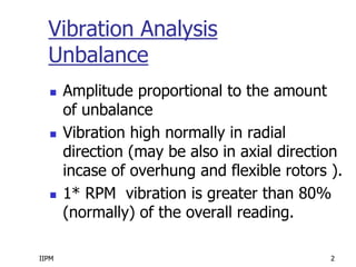
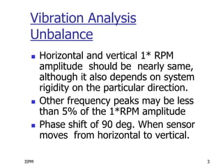
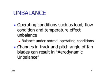
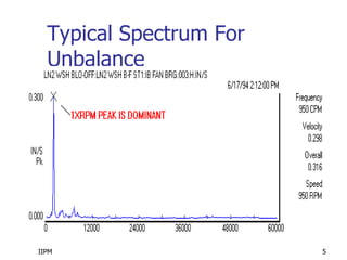
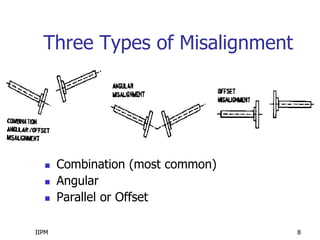
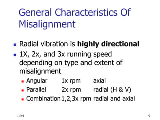
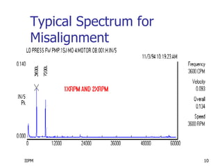
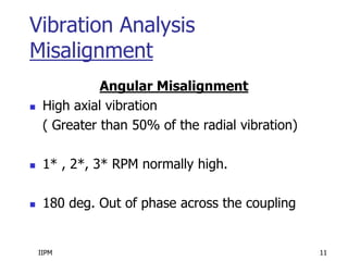
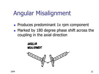
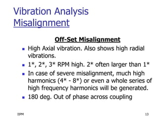
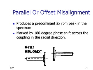
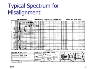
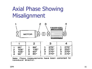
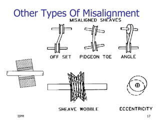
1) Unbalance causes 1x RPM vibration and can be identified by horizontal and vertical amplitudes being nearly the same. Misalignment produces 1x, 2x, or 3x RPM vibrations depending on the type and can be identified by directional radial vibration and phase shifts across couplings.
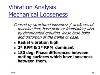
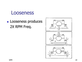
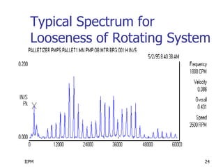
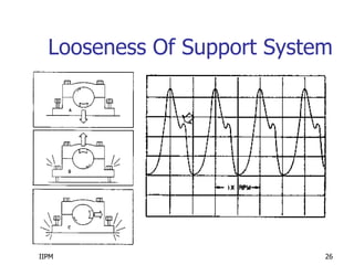
2) Mechanical looseness is caused by loose machine components or supports. Looseness of rotating parts causes multiple harmonics while loose supports produce 1x and 2x RPM vibrations. Looseness is identified by directional vibration and phase differences across loose interfaces.
3) The document provides details on identifying unbalance, the three types of misalignment, and looseness