Vhdlbputspdas
•Download as DOC, PDF•
2 likes•733 views

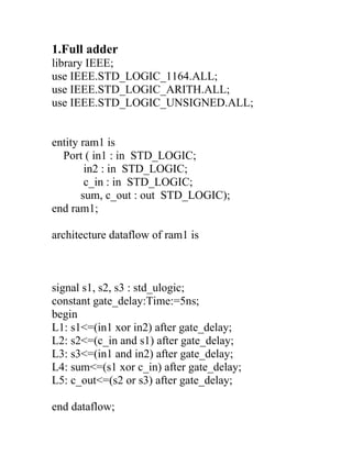
The document contains code for several basic digital logic components including: 1. A full adder described using signals and delays. 2. A 4:1 multiplexer using elsif statements to select the output. 3. A 4:1 multiplexer using a when statement to select the output. 4. A 1:4 demultiplexer using if/elsif statements to activate one output. 5. A full adder described behaviorally using boolean expressions. 6. A D latch with an output that follows the input on the positive clock edge. 7. A D flip-flop with an output that follows the input on the positive clock edge.
Report
Share
Report
Share

Recommended
Vhdl lab manual
The document describes 8 experiments involving VHDL code implementations of various digital logic circuits. Experiment 1 implements 4:1 and 8:1 multiplexers. Experiment 2 implements 1:4 and 1:8 demultiplexers. Experiment 3 implements a 3:8 decoder. Experiment 4 implements a 4-bit adder. Experiment 5 implements a 4-bit comparator. Experiment 6 implements a 2-bit ALU. Experiment 7 and 8 both implement a D flip-flop. The document provides the full VHDL code for each circuit implementation.
Digital to analog -Sqaure waveform generator in VHDL
The document contains VHDL code for generating a square wave signal. It includes an entity that defines the ports and architecture for a square_wave module. The module uses a counter and flip-flop to toggle a signal on each clock cycle, producing a square wave output. A testbench is provided to simulate the module and check its output waveform.
Digital system design practical file
The document describes VHDL programs for implementing half adder and full adder circuits using behavioral modeling. It includes the VHDL code, RTL schematic, technology schematic, truth tables, and test benches for each circuit. The half adder program uses an XOR gate for the sum output and AND gate for the carry output. The full adder program uses XOR gates and AND gates to calculate the sum and carry outputs from three inputs of A, B, and a carry in. Test benches are provided to simulate and test the behavior of each design.
Dsd lab Practical File
This document provides VHDL code for implementing various logic gates and basic digital circuits. It includes code for AND, OR, NOT, NAND, NOR, XOR and XNOR gates. It also provides code for half adder, full adder, multiplexer, demultiplexer, decoder, encoder, comparator, BCD to binary converter, JK flip-flop, and an n-bit counter. For each circuit, the VHDL code and a sample waveform output is given. The purpose is to design these basic digital components using VHDL and simulate their behavior.
Programs of VHDL
The document contains 7 VHDL programs with the following objectives:
1) Implement a 3:8 decoder using behavioral modeling.
2) Implement an 8:1 multiplexer using behavioral modeling.
3) Implement a 1:8 demultiplexer using behavioral modeling.
4) Implement 4-bit addition/subtraction.
5) Implement a 4-bit comparator.
6) Generate a MOD-10 up counter.
7) Generate a 1010 sequence detector.
Each program contains the VHDL code, RTL logic diagram and output waveform to achieve the given objective.
Reporte vhd10
The document describes a digital clock design project implemented in VHDL. The clock displays hours and minutes in 24-hour format using 7-segment displays. Key components include a clockSecond module to generate clock pulses, a counter7seg module to count the time, an anodeController module to multiplex the displays, and a sevenSelect module to select the correct display digit based on the anode lines. The design was tested and able to correctly count and display the time in hours and minutes.
VHDL PROGRAMS FEW EXAMPLES
This document contains 18 VHDL code examples that implement various digital logic circuits including basic gates, full adders, multiplexers, flip-flops, counters, encoders, decoders, and a state machine. The examples range from simple combinational logic to more complex sequential circuits. Taken together, the document provides a overview of how to model fundamental building blocks of digital systems using VHDL.
Experiment write-vhdl-code-for-realize-all-logic-gates
The document describes an experiment to write VHDL code for basic logic gates. It includes the truth tables, logic diagrams, and VHDL code for AND, OR, NOT, NAND, NOR, and EXOR gates. Waveform diagrams are provided to simulate the behavior of each gate.
Data Flow Modeling
The document describes data flow modeling in VHDL. It discusses how data flow style architecture models hardware in terms of the movement of data over continuous time between combinational logic components. It also describes how concurrent signal assignment statements can be used to model simple combinational logic. Examples provided include half adder, full adder, comparator, multiplexer, decoder, and arithmetic logic unit designs modeled using data flow style and concurrent signal assignments.
VHdl lab report
The document describes the implementation of various digital logic circuits like D latch, D flip flop, JK flip flop, multiplexers, decoders, counters etc. using VHDL. It includes the VHDL code, test benches and synthesis reports for each circuit. The aim is to design the circuits in behavioral and structural modeling and verify their functionality.
Reporte vhdl9
The document describes a VHDL implementation of a 2-digit countdown timer using Aldec HDL and a Basys2 kit. It includes the VHDL code for the timer modules: clockSecond generates the clock signal, counter7seg controls the counting, binary7decoder decodes the digits to 7-segment displays, and sevenSelect multiplexes which digit is displayed. The top-level diagram shows how the modules are connected to implement the 2-digit timer functionality.
Vhdl programs
The document contains VHDL code for several basic digital logic components including a parallel-in parallel-out shift register, serial-in parallel-out shift register, 4-bit binary counter, 4-bit ring counter, RS latch, D latch, SR flip-flop, and D flip-flop. The code uses processes, signals, ports, and architectures to model the behavior and dataflow of each component.
radix_4 fft dif with mdc and mdf
radix_4 fft processor can be determine to creating for four channel and if it is from how moving the data from one stage to another stage and how get correct output equal to input.
the main advantage:creating for multiple channel from group of channel and analysis how moving of data from stage by stage,
increasing for data processing speed,
Writing more complex models
Modeling more complicated logic using sequential statements
Skills gained:
1- Identify sequential environment in VHDL
2- Model simple sequential logic
This is part of VHDL 360 course
DHow2 - L6 VHDL
The document describes processes in VHDL. It defines a process as a concurrent statement that contains sequential logic. Processes run in parallel and can be conditioned by a sensitivity list or wait statement. Local variables retain their values between executions. It provides an example of a process with a sensitivity list and one with a wait statement. It also summarizes the general structure of a VHDL program and describes different types of process control including if-then-else, case statements, and decoders. Additional topics covered include flip-flops, counters, and finite state machines.
Dsd prac1
The document describes the source code and waveforms for several digital logic gates and circuits implemented using VHDL, including AND, OR, NOT, XOR, and XNOR gates using both data flow and behavioral modeling styles. Multiplexers, half adders, full adders, decoders, and 1-bit and 4-bit comparators are also implemented and their functionality demonstrated with waveforms.
94257825 bao-cao-pld
This document provides VHDL code for several digital logic circuits including decoders, counters, multiplexers and demultiplexers. It includes 4 sections: 1) decoder circuits for 2-to-4 and 3-to-8 decoding, 2) a 4-bit counter, 3) combinational logic circuits including decoders, encoders and a 74138 decoder, and 4) multiplexer circuits including 4-to-1 and 8-to-1 multiplexers and a 74151 demultiplexer. The VHDL code and test simulations are provided for each circuit.
VHDL Behavioral Description
This presentation discusses the sequential statements in VHDL and other aspects of VHDL behavioral description. All codes in simulated in Xilinx ISE.
Home automation system
This document summarizes an EE-323 semester project on a home automation system. It includes sections that describe the project plan involving fan speed control using temperature sensors, indoor light control using IR sensors, outdoor light dimming using LDR sensors, and automatic and manual control modules. It provides schematics, flow charts, code explanations, and simulations for each module. The document aims to provide details on implementing a home automation system by concatenating different control modules together using a microcontroller.
Digital system design lab manual
The document contains the list of experiments for the Digital System Design lab at Sri Venkateswara College of Engineering & Technology. The experiments include simulation and verification of logic gates, modeling of adders like half adder, full adder, ripple carry adder, carry look ahead adder and serial adder. Other experiments involve modeling of decoders, multiplexers, encoders and flip-flops. Additional experiments are design of counters, registers, sequence detectors, multipliers and ALU. The document also lists experiments on RAM operations and implementation of stacks and queues.
Appsec obfuscator reloaded
This document summarizes an obfuscation technique called function merging. It describes creating a single merge function that acts as a dispatcher for other functions via a switch statement. The merge function loads arguments, replaces returns, and moves function content. Wrappers are created to call the merge function and avoid API breakage.
Device Modeling of Oscillator using PSpice
This document describes a PSpice model of an oscillator circuit. The model includes an equivalent circuit with resistors, capacitors, voltage sources and switches to simulate the oscillator. The document provides parameters for the high and low voltage levels and output current of the oscillator that can be set in the simulation.
Arduino Workshop 2011.05.31
This document contains code snippets for controlling an LED or reading sensor values using an Arduino board. The snippets demonstrate basic digital input/output functions like turning an LED on and off, fading an LED brightness over time, reading the state of a push button to control an LED, reading analog sensor values to control LED brightness, receiving serial data to set LED brightness, and sending mouse position data over serial.
Programming arduino makeymakey
This document provides information about the Arduino workshop. It discusses Arduino boards and their components. It describes the Arduino IDE and basic code structure using functions like pinMode(), digitalWrite(), and delay(). It also explains programming concepts like variables, loops, and using sensors and actuators with digital and analog input/output pins.
VLSI Anna University Practical Examination
The document outlines an examination for a VLSI design lab course. It contains 24 questions to be completed in 3 hours. For each question, students are instructed to either simulate a digital circuit using Xilinx ISE 9.1i software or implement the circuit using an XC3S400 FPGA trainer kit. The circuits include adders, encoders, decoders, multipliers, flip-flops, and basic logic gates.
Fpga creating counter with external clock
The document describes the design and implementation of a seven segment counter on an FPGA. It includes the implementation of a prescaler, debouncing circuit, binary coded decimal (BCD) counter, and seven segment decoder. The prescaler was initially generating a warning about excessive skew, which was resolved by adding a clock buffer to the prescaler output. The design components are instantiated and connected in the top level system counter entity.
JavaFest. Виктор Полищук. Legacy: как победить в гонке
У вас древний проект? Все зовут его «Legacy», а вас «неудачник»? Возможно они даже смеются над вами.
Давайте взглянем на ситуацию с другого ракурса. Все (все, Карл!) успешные проекты рано или поздно превращаются в Legacy-проекты.
Я затрону тему Legacy не просто как явление, а как возможность быть постоянно в тренде, прослыть супер-спецом (даже если ты знаешь всего два фреймворка), сделать карьеру, как делать, то что ты хочешь, а не то что тебя просят. Ладно, ладно, я наврал про два фреймворка, но все остальное чистая правда. Я покажу, что вы можете творить, имея правильный подход к Legacy коду.
Суть в том, что Legacy — это не грустно/уныло/немодно, это просто/клево/весело, если с умом подойти к задаче!
correctionTD-1-vhdl2947.pptx
This document contains VHDL code for multiplexer circuits and corrections for exercises on VHDL code. It includes:
1. Four ways to write VHDL code for a 2-to-1 multiplexer using different assignment methods.
2. Corrections for an exercise involving VHDL code for a circuit with 4 inputs and 2 outputs based on different input patterns.
3. The corrections provide 4 different ways to write the VHDL code using selective assignment, conditional assignment, if-then-else structure, and case-when structure.
4. VHDL code for a simple circuit with 2 inputs, 1 select line, and 1 output using an if-then process.
vhdll.docx
The document describes VHDL code for 5 exercises:
1. Code to control 8 LEDs blinking in a circle.
2. Code for a down counter module from 8 to 0.
3. Code for a BCD down counter displaying on 7-segment LEDs from 59 to 00.
4. Code for a 1-of-16 decoder with enable.
5. Code for a JK flip-flop circuit and its testbench.
correctionTD-2-vhdl2949.pptx
The document contains code for multiple VHDL programs. The first program defines an entity with ports for two 8-bit inputs, a 2-bit selector, and an 8-bit output. Based on the selector value, the output will be the sum, difference, AND, or OR of the two inputs. The second program defines a circuit with inputs A, B, a selector, a clock, and an output. It uses the inputs to compute two signals based on the selector, and outputs the selected signal on the clock edge. The third program defines an entity with 4 8-bit inputs, a selector, and a sum output. Based on the selector, it assigns the first two inputs to signals and adds them,
More Related Content
What's hot
Data Flow Modeling
The document describes data flow modeling in VHDL. It discusses how data flow style architecture models hardware in terms of the movement of data over continuous time between combinational logic components. It also describes how concurrent signal assignment statements can be used to model simple combinational logic. Examples provided include half adder, full adder, comparator, multiplexer, decoder, and arithmetic logic unit designs modeled using data flow style and concurrent signal assignments.
VHdl lab report
The document describes the implementation of various digital logic circuits like D latch, D flip flop, JK flip flop, multiplexers, decoders, counters etc. using VHDL. It includes the VHDL code, test benches and synthesis reports for each circuit. The aim is to design the circuits in behavioral and structural modeling and verify their functionality.
Reporte vhdl9
The document describes a VHDL implementation of a 2-digit countdown timer using Aldec HDL and a Basys2 kit. It includes the VHDL code for the timer modules: clockSecond generates the clock signal, counter7seg controls the counting, binary7decoder decodes the digits to 7-segment displays, and sevenSelect multiplexes which digit is displayed. The top-level diagram shows how the modules are connected to implement the 2-digit timer functionality.
Vhdl programs
The document contains VHDL code for several basic digital logic components including a parallel-in parallel-out shift register, serial-in parallel-out shift register, 4-bit binary counter, 4-bit ring counter, RS latch, D latch, SR flip-flop, and D flip-flop. The code uses processes, signals, ports, and architectures to model the behavior and dataflow of each component.
radix_4 fft dif with mdc and mdf
radix_4 fft processor can be determine to creating for four channel and if it is from how moving the data from one stage to another stage and how get correct output equal to input.
the main advantage:creating for multiple channel from group of channel and analysis how moving of data from stage by stage,
increasing for data processing speed,
Writing more complex models
Modeling more complicated logic using sequential statements
Skills gained:
1- Identify sequential environment in VHDL
2- Model simple sequential logic
This is part of VHDL 360 course
DHow2 - L6 VHDL
The document describes processes in VHDL. It defines a process as a concurrent statement that contains sequential logic. Processes run in parallel and can be conditioned by a sensitivity list or wait statement. Local variables retain their values between executions. It provides an example of a process with a sensitivity list and one with a wait statement. It also summarizes the general structure of a VHDL program and describes different types of process control including if-then-else, case statements, and decoders. Additional topics covered include flip-flops, counters, and finite state machines.
Dsd prac1
The document describes the source code and waveforms for several digital logic gates and circuits implemented using VHDL, including AND, OR, NOT, XOR, and XNOR gates using both data flow and behavioral modeling styles. Multiplexers, half adders, full adders, decoders, and 1-bit and 4-bit comparators are also implemented and their functionality demonstrated with waveforms.
94257825 bao-cao-pld
This document provides VHDL code for several digital logic circuits including decoders, counters, multiplexers and demultiplexers. It includes 4 sections: 1) decoder circuits for 2-to-4 and 3-to-8 decoding, 2) a 4-bit counter, 3) combinational logic circuits including decoders, encoders and a 74138 decoder, and 4) multiplexer circuits including 4-to-1 and 8-to-1 multiplexers and a 74151 demultiplexer. The VHDL code and test simulations are provided for each circuit.
VHDL Behavioral Description
This presentation discusses the sequential statements in VHDL and other aspects of VHDL behavioral description. All codes in simulated in Xilinx ISE.
Home automation system
This document summarizes an EE-323 semester project on a home automation system. It includes sections that describe the project plan involving fan speed control using temperature sensors, indoor light control using IR sensors, outdoor light dimming using LDR sensors, and automatic and manual control modules. It provides schematics, flow charts, code explanations, and simulations for each module. The document aims to provide details on implementing a home automation system by concatenating different control modules together using a microcontroller.
Digital system design lab manual
The document contains the list of experiments for the Digital System Design lab at Sri Venkateswara College of Engineering & Technology. The experiments include simulation and verification of logic gates, modeling of adders like half adder, full adder, ripple carry adder, carry look ahead adder and serial adder. Other experiments involve modeling of decoders, multiplexers, encoders and flip-flops. Additional experiments are design of counters, registers, sequence detectors, multipliers and ALU. The document also lists experiments on RAM operations and implementation of stacks and queues.
Appsec obfuscator reloaded
This document summarizes an obfuscation technique called function merging. It describes creating a single merge function that acts as a dispatcher for other functions via a switch statement. The merge function loads arguments, replaces returns, and moves function content. Wrappers are created to call the merge function and avoid API breakage.
Device Modeling of Oscillator using PSpice
This document describes a PSpice model of an oscillator circuit. The model includes an equivalent circuit with resistors, capacitors, voltage sources and switches to simulate the oscillator. The document provides parameters for the high and low voltage levels and output current of the oscillator that can be set in the simulation.
Arduino Workshop 2011.05.31
This document contains code snippets for controlling an LED or reading sensor values using an Arduino board. The snippets demonstrate basic digital input/output functions like turning an LED on and off, fading an LED brightness over time, reading the state of a push button to control an LED, reading analog sensor values to control LED brightness, receiving serial data to set LED brightness, and sending mouse position data over serial.
Programming arduino makeymakey
This document provides information about the Arduino workshop. It discusses Arduino boards and their components. It describes the Arduino IDE and basic code structure using functions like pinMode(), digitalWrite(), and delay(). It also explains programming concepts like variables, loops, and using sensors and actuators with digital and analog input/output pins.
VLSI Anna University Practical Examination
The document outlines an examination for a VLSI design lab course. It contains 24 questions to be completed in 3 hours. For each question, students are instructed to either simulate a digital circuit using Xilinx ISE 9.1i software or implement the circuit using an XC3S400 FPGA trainer kit. The circuits include adders, encoders, decoders, multipliers, flip-flops, and basic logic gates.
Fpga creating counter with external clock
The document describes the design and implementation of a seven segment counter on an FPGA. It includes the implementation of a prescaler, debouncing circuit, binary coded decimal (BCD) counter, and seven segment decoder. The prescaler was initially generating a warning about excessive skew, which was resolved by adding a clock buffer to the prescaler output. The design components are instantiated and connected in the top level system counter entity.
JavaFest. Виктор Полищук. Legacy: как победить в гонке
У вас древний проект? Все зовут его «Legacy», а вас «неудачник»? Возможно они даже смеются над вами.
Давайте взглянем на ситуацию с другого ракурса. Все (все, Карл!) успешные проекты рано или поздно превращаются в Legacy-проекты.
Я затрону тему Legacy не просто как явление, а как возможность быть постоянно в тренде, прослыть супер-спецом (даже если ты знаешь всего два фреймворка), сделать карьеру, как делать, то что ты хочешь, а не то что тебя просят. Ладно, ладно, я наврал про два фреймворка, но все остальное чистая правда. Я покажу, что вы можете творить, имея правильный подход к Legacy коду.
Суть в том, что Legacy — это не грустно/уныло/немодно, это просто/клево/весело, если с умом подойти к задаче!
What's hot (19)
JavaFest. Виктор Полищук. Legacy: как победить в гонке
JavaFest. Виктор Полищук. Legacy: как победить в гонке
Similar to Vhdlbputspdas
correctionTD-1-vhdl2947.pptx
This document contains VHDL code for multiplexer circuits and corrections for exercises on VHDL code. It includes:
1. Four ways to write VHDL code for a 2-to-1 multiplexer using different assignment methods.
2. Corrections for an exercise involving VHDL code for a circuit with 4 inputs and 2 outputs based on different input patterns.
3. The corrections provide 4 different ways to write the VHDL code using selective assignment, conditional assignment, if-then-else structure, and case-when structure.
4. VHDL code for a simple circuit with 2 inputs, 1 select line, and 1 output using an if-then process.
vhdll.docx
The document describes VHDL code for 5 exercises:
1. Code to control 8 LEDs blinking in a circle.
2. Code for a down counter module from 8 to 0.
3. Code for a BCD down counter displaying on 7-segment LEDs from 59 to 00.
4. Code for a 1-of-16 decoder with enable.
5. Code for a JK flip-flop circuit and its testbench.
correctionTD-2-vhdl2949.pptx
The document contains code for multiple VHDL programs. The first program defines an entity with ports for two 8-bit inputs, a 2-bit selector, and an 8-bit output. Based on the selector value, the output will be the sum, difference, AND, or OR of the two inputs. The second program defines a circuit with inputs A, B, a selector, a clock, and an output. It uses the inputs to compute two signals based on the selector, and outputs the selected signal on the clock edge. The third program defines an entity with 4 8-bit inputs, a selector, and a sum output. Based on the selector, it assigns the first two inputs to signals and adds them,
Basic-VHDL-Constructs1.ppt
The document discusses VHDL including:
1. Keywords like entities, architectures, ports and components for building basic logic gates and a 2:1 multiplexer using structural, behavioral and test bench modeling.
2. Finite state machines including examples of Mealy and Moore models for asynchronous and synchronous state machines.
3. Generic clauses to customize delays in designs.
Fpga creating counter with internal clock
This document describes a design for a counter seven segment display using an FPGA. The author implemented a counter component and a decoder component, then wired them together in a top-level systemSeg entity using port mapping. The counter counts from 0 to 9 and outputs a 4-bit binary coded decimal value. The decoder converts the 4-bit input to a 7-segment display output based on a case statement. The author notes that port mapping is useful for wiring components together in HDL and that designs need to be synchronous with a clock.
hdl timer ppt.pptx
The timer project uses a FPGA board to display elapsed time on a seven segment display. It is implemented using VHDL with hardware blocks that include a BCD counter, HEX decoder, and finite state machine (FSM). The BCD counter counts the time in binary coded decimal format. The HEX decoder converts the BCD output to the hexadecimal display format for the seven segment display. The FSM controls the different states of the timer for the start, stop, and reset functions using the button inputs.
Vhdl
The VHDL code implements a 4-input priority encoder with one hot encoding. It uses an if-else conditional statement to assign a 2-bit binary code to the output y based on the highest priority input bit set in w. It also assigns z to 0 if no inputs are set in w, and 1 otherwise.
Sequence detector for "111"
The document contains VHDL code that implements a Moore finite state machine (FSM) with 3 states (s1, s2, s3) to detect a sequence of 3 ones. The FSM has an input x, a clock clk, a reset rst, and an output z. It transitions between states and sets z based on the current state and value of x on each clock edge. A testbench simulates the FSM by applying a repeating sequence of ones to x over multiple clock cycles while monitoring z.
Presentation1.pdf
This document contains VHDL code for several digital logic components including:
- A 4-bit register module with inputs for the data and enable/clock signals and outputs for the registered data.
- Full adder modules using both structural and behavioral modeling with inputs for two bits to add and a carry in and outputs for the sum and carry out.
- Half adder and full adder components used as building blocks for the structural full adder.
- Basic D flip-flop with inputs for data and clock and an output for the registered data.
Digital System Design Lab Report - VHDL ECE
The document describes the implementation of 16-bit and 64-bit shift registers using VHDL in data flow modeling. It includes the VHDL code, test bench, and simulation results for shift registers that shift the values in the input register right by 1 bit position on the positive edge of the clock. The 16-bit shift register outputs the shifted value on q1 and the 64-bit shift register outputs the shifted value on q2. The design and functionality of both shift registers are verified through simulation.
Vhdl
Data flow modeling describes hardware using the movement of data between combinational logic components over time. It models circuits at the register transfer level using logical and relational operators and concurrent signal assignments. This style is best for modeling data-driven circuits like arithmetic logic units. Examples shown include half adders, full adders, decoders, multiplexers, and an 8-bit adder modeled using data flow and concurrent assignments.
Design of Mux and decoder using VHDL
The document describes a VHDL code for an 8-to-1 multiplexer. The multiplexer has 8 inputs, 3 select lines, and 1 output. The VHDL code uses a case statement to select the appropriate input pin to connect to the output pin based on the value on the select lines.
W8_2: Inside the UoS Educational Processor
In this unit we provide more details to the UoS educational, in particular it's implementation in VHDL.
Unit duration: 50mn.
License: LGPL 2.1
selected input/output - sensors and actuators
Selected Input/Output - Sensors & Actuators
LDR Laser Receiver, PIR Sensor, LM35, DHT11, Ultrasonic Sensor HC SR04
Local Input/Output with Processing.org
Timer ppt
This document describes a group project to design a stopwatch using VHDL on an FPGA board. The stopwatch will use switches as inputs to start, stop, and reset and will display the elapsed time on seven-segment displays. The design is broken into blocks - a clock module, binary-coded decimal counter, finite-state machine to control states, and hex decoder. The blocks are implemented using structural modeling in VHDL files and interconnected in a main file to realize the stopwatch functionality.
32 bit ALU Chip Design using IBM 130nm process technology
- Implemented a 32 bit Arithmetic/Logic unit in VHDL using behavioral Modeling which involves all basic ALU operations including special functionality like binary-to-grey code conversion, parity check, sum of first N numbers. Simulation is performed in ModelSim IDE.
- Involved design using Cadence (Virtuoso Layout/Schematic) and Hspice simulation of standard library cell.
- Involved library characterization using NCX, RTL synthesis of VHDL code using Synopsys Design Vision, auto placement & routing using Encounter, static timing analysis using Synopsys Primetime.
Vhdl programming
This document provides examples of VHDL code for modeling basic logic gates and multiplexers. It begins with syntax for VHDL programs and then provides behavioral VHDL code for modeling common logic gates like AND, OR, NOR, NAND, XOR and XNOR gates. It also provides code for half adder, full adder, half subtractor and full subtractor. The document further contains VHDL code examples to model a 4-to-1 multiplexer and 1-to-4 demultiplexer using different types of statements like if-else, case, when-else and with-select.
VLSI Lab manual PDF
The document describes the design and simulation of half adders, full adders, multiplexers, and demultiplexers using VHDL. It includes block diagrams, truth tables, and VHDL code for implementing these circuits using dataflow, behavioral, and structural modeling in Xilinx ISE. Code examples and output waveforms are provided for half adders, full adders, 4-to-1 multiplexers, and 1-to-4 demultiplexers. The aim is to learn how to design and simulate basic digital circuits using different VHDL modeling approaches.
Pipeline stalling in vhdl
This document describes a VLSI design project to implement pipeline stalling using VHDL. It includes modules for registers, multiplexers, an ALU, and a pipelined multiplier. The coding technique uses registers to move data between pipeline stages on a common clock. Simulation waveforms show the pipeline functioning as intended. Pipelining is commonly used to increase throughput in multicore computers, operating system design, superscalar processors, and firmware.
Java Bytecode Crash Course [Code One 2019]
Java bytecode lies at the foundation of the the entire Java ecosystem. Regardless of what language and tools you use, if you run on the JVM, you’re using Java bytecode. Although understanding bytecode is not a requirement for all developers, a deeper understanding of how your code runs on the JVM can make understanding and resolving certain types of issues much easier. Understanding bytecode also opens the door to more-advanced techniques such as bytecode instrumentation via JVMTI and writing your own Java agent. This session starts at the very beginning and covers all the basics, with a heavy emphasis on examples.
Similar to Vhdlbputspdas (20)
32 bit ALU Chip Design using IBM 130nm process technology
32 bit ALU Chip Design using IBM 130nm process technology
More from GIET,Bhubaneswar
Dct and adaptive filters
The document discusses the discrete cosine transform (DCT) and compares it to the discrete Fourier transform (DFT). Some key points:
- DCT provides better energy compaction than DFT, making it useful for image/signal compression applications. It transforms a signal from the spatial domain to the frequency domain.
- DCT is a real-valued transform derived from DFT, but is more computationally efficient as it avoids redundant complex calculations for real input data.
- The one-dimensional and two-dimensional DCT transforms are defined. DCT has properties like separability and invertibility like DFT.
- DCT coefficients represent the signal's frequency content, with low frequencies concentrated in
Lead a better life
This document discusses living a better life through making deliberate choices and having a positive impact on others. It suggests living with kindness by helping others each day and keeping promises to build trust. Examples are given of individuals who overcame difficulties through hard work and determination to achieve career success, with the goal of supporting their families. Videos are also referenced that provide additional perspectives on self-improvement and challenge. The overall message is about accepting life's challenges in a positive manner.
Stress management
This document discusses stress, its causes and effects, and various stress management techniques. It defines stress as the body's physical, mental or emotional response to events that cause tension. Both moderate and excessive stress can impact health, with moderate levels possibly improving performance but too much leading to negative physical and mental symptoms. The document outlines common stressors like work, family, health issues and the environment. It also lists potential stress symptoms and debunks some myths about stress. Finally, it recommends various stress management strategies like exercise, relaxation, time management, positive thinking and making lifestyle changes.
Four squares
The document presents a series of questions that involve dividing the white space in four squares (A, B, C, D) into equal pieces. It asks the reader to divide square A into two pieces, square B into three pieces, square C into four pieces, and square D into seven pieces. It then provides the answers to each question, with the division of square D into seven pieces being posed as the most challenging. The document encourages readers not to overcomplicate problems and solutions.
Positive thinking
The document discusses principles of positive youth development and education programs. It emphasizes focusing on desired positive outcomes for youth rather than preventing negative ones. Effective programs provide safety, belonging, competence-building experiences, independence, self-awareness, self-worth, and opportunities to contribute through relationships and support in families, schools, and communities. The goal is developing the whole person through intentional processes that promote positive youth participation and development.
Vlsi giet
The document discusses VLSI (Very Large Scale Integration) and the history and trends in integrated circuit technology. It explains the progression from SSI to VLSI from the 1950s to present day, with increasing numbers of transistors per chip. It also defines different integration levels and provides examples of processor sizes for different silicon process technologies.
Spdas2 vlsibput
VHDL is a hardware description language used to model and design digital circuits. It can be used for simulation, synthesis, and verification of circuits. VHDL has different language elements like entities, architectures, processes, and packages that allow modeling at different levels of abstraction like behavioral, dataflow, and structural. Common data types in VHDL include std_logic, std_logic_vector, and integers. VHDL supports modeling concurrency using processes and signal assignments.
Spdas1 vlsibput
VLSI stands for Very Large Scale Integration and refers to integrated circuits with over 100,000 transistors. The document discusses the history and progression of integration levels from SSI to VLSI to ULSI. It also describes the photolithography process used to etch circuit designs onto silicon wafers at the microscopic level needed for modern integrated circuits.
More from GIET,Bhubaneswar (8)
Vhdlbputspdas
- 1. 1.Full adder library IEEE; use IEEE.STD_LOGIC_1164.ALL; use IEEE.STD_LOGIC_ARITH.ALL; use IEEE.STD_LOGIC_UNSIGNED.ALL; entity ram1 is Port ( in1 : in STD_LOGIC; in2 : in STD_LOGIC; c_in : in STD_LOGIC; sum, c_out : out STD_LOGIC); end ram1; architecture dataflow of ram1 is signal s1, s2, s3 : std_ulogic; constant gate_delay:Time:=5ns; begin L1: s1<=(in1 xor in2) after gate_delay; L2: s2<=(c_in and s1) after gate_delay; L3: s3<=(in1 and in2) after gate_delay; L4: sum<=(s1 xor c_in) after gate_delay; L5: c_out<=(s2 or s3) after gate_delay; end dataflow;
- 2. 2. 4:1 MUX (elsif) library IEEE; use IEEE.STD_LOGIC_1164.ALL; use IEEE.STD_LOGIC_ARITH.ALL; use IEEE.STD_LOGIC_UNSIGNED.ALL; entity mux1 is Port ( i : in STD_LOGIC_VECTOR (03 downto 0); s : in STD_LOGIC_VECTOR (01 downto 0); out1 : out STD_LOGIC); end mux1; architecture Behavioral of mux1 is begin process (s) begin if s="00" then out1<=i(0); elsif s="01" then out1<=i(1); elsif s="10" then out1<=i(2); elsif s="11" then out1<=i(3); end if; end process; end Behavioral;
- 3. 3. 4:1MUX using “when” library IEEE; use IEEE.STD_LOGIC_1164.ALL; use IEEE.STD_LOGIC_ARITH.ALL; use IEEE.STD_LOGIC_UNSIGNED.ALL; entity mux1 is Port ( i : in STD_LOGIC_VECTOR (03 downto 0); s : in STD_LOGIC_VECTOR (01 downto 0); out1 : out STD_LOGIC); end mux1; architecture Behavioral of mux1 is begin out1<= i(0) when (s=”00”) else out1<= i(1) when (s=”01”) else out1<= i(2) when (s=”10”) else out1<= i(3) when (s=”11”) ; end behavioral; 4. 1:4 DeMUX Entity demux_4 is Port (En: in std_logic;
- 4. Y0,Y1,Y2,Y3: out std_logic; i: in std_logic_vector (01 downto 00)); end demux_4; architecture of demux_4 is begin if i=”00” then Y0<=En; Y1<=’0’; Y2<=’0’; Y3<=’0’; elsif i=”01” then Y0<=’0’; Y1<=’En’; Y2<=’0’; Y3<=’0’; elsif i=”10” then Y0<=’0’; Y1<=’0’; Y2<=’En’; Y3<=’0’; elsif i=”11” then Y0<=’0’; Y1<=’0’; Y2<=’0’; Y3<=’En’; end behavioral;
- 5. 5. Full Adder (Behavioral) entity Add is port(a,b,ci:in std_logic; s,co: out std_logic); end add; architecture behavioral of Add is begin s<= ‘1’ when (a=’0’ and b=’1’ and ci=’0’) else ‘1’ when (a=’1’ and b=’0’ and ci=’0’) else ‘1’ when (a=’0’ and b=’0’ and ci=’1’) else ‘1’ when (a=’1’ and b=’1’ and ci=’1’) else ‘0’; c0<= ‘1’ when (a=’1’ and b=’1’ and ci=’0’) else ‘1’ when (a=’0’ and b=’1’ and ci=’1’) else ‘1’ when (a=’1’ and b=’0’ and ci=’1’) else ‘1’ when (a=’1’ and b=’1’ and ci=’1’) else ‘0’; end Add;
- 6. 6. D Latch entity D_latch is port (D: in std_logic; Q: out std_logic); end D_latch; architecture behavioral of D_latch is begin process(clk , D) begin if (clk=’1’) then Q<= D; end if; end process; end behavioral;
- 7. 7. D F/F (positive and negative edge trigger) entity DFF is port (D: in std_logic; Q: out std_logic); end DFF; architecture behavioral of DFF is begin process(clk , D) begin if (clk ‘event and clk=’1’) then Q<= D; end if; end process; end behavioral;