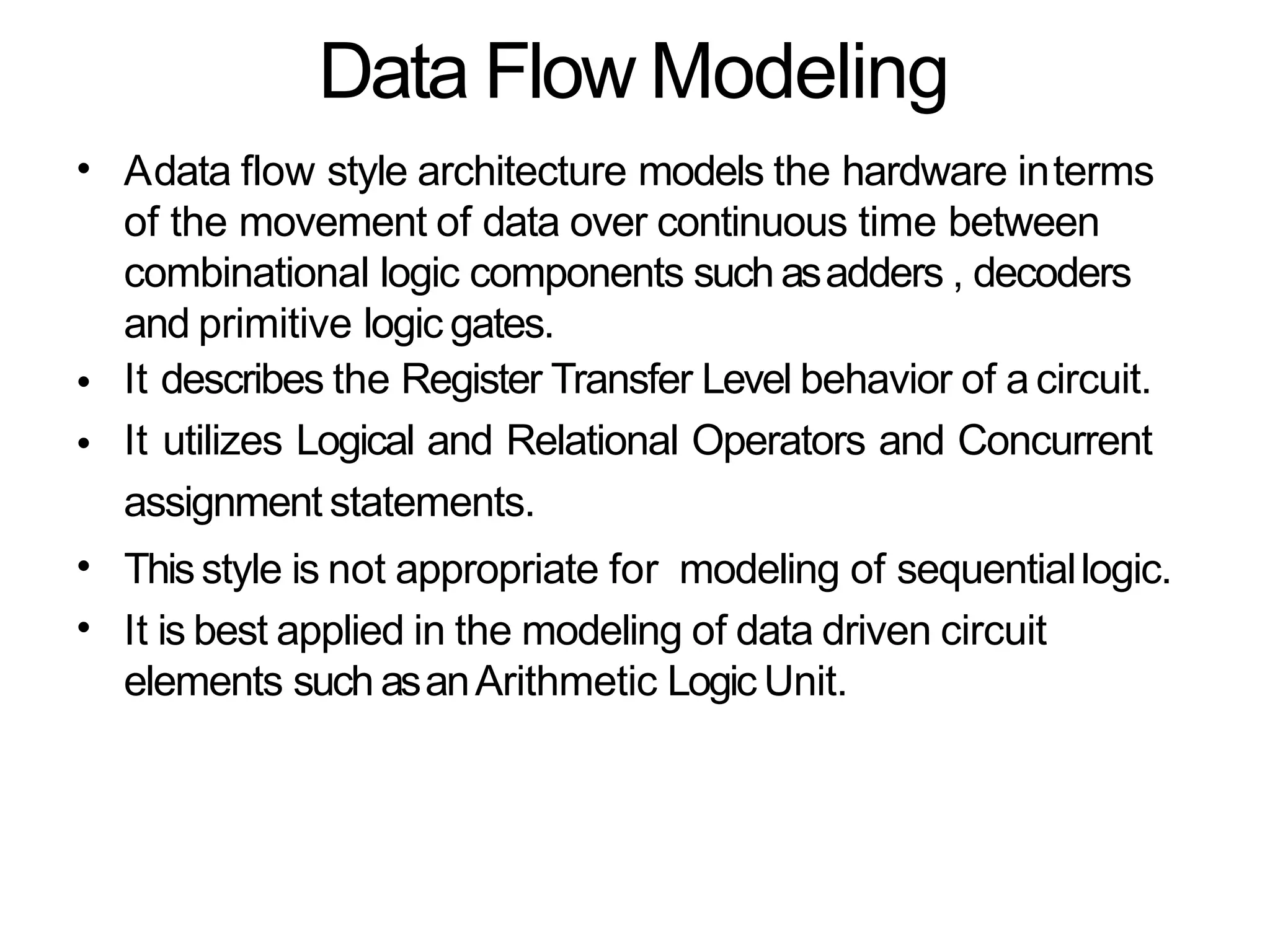
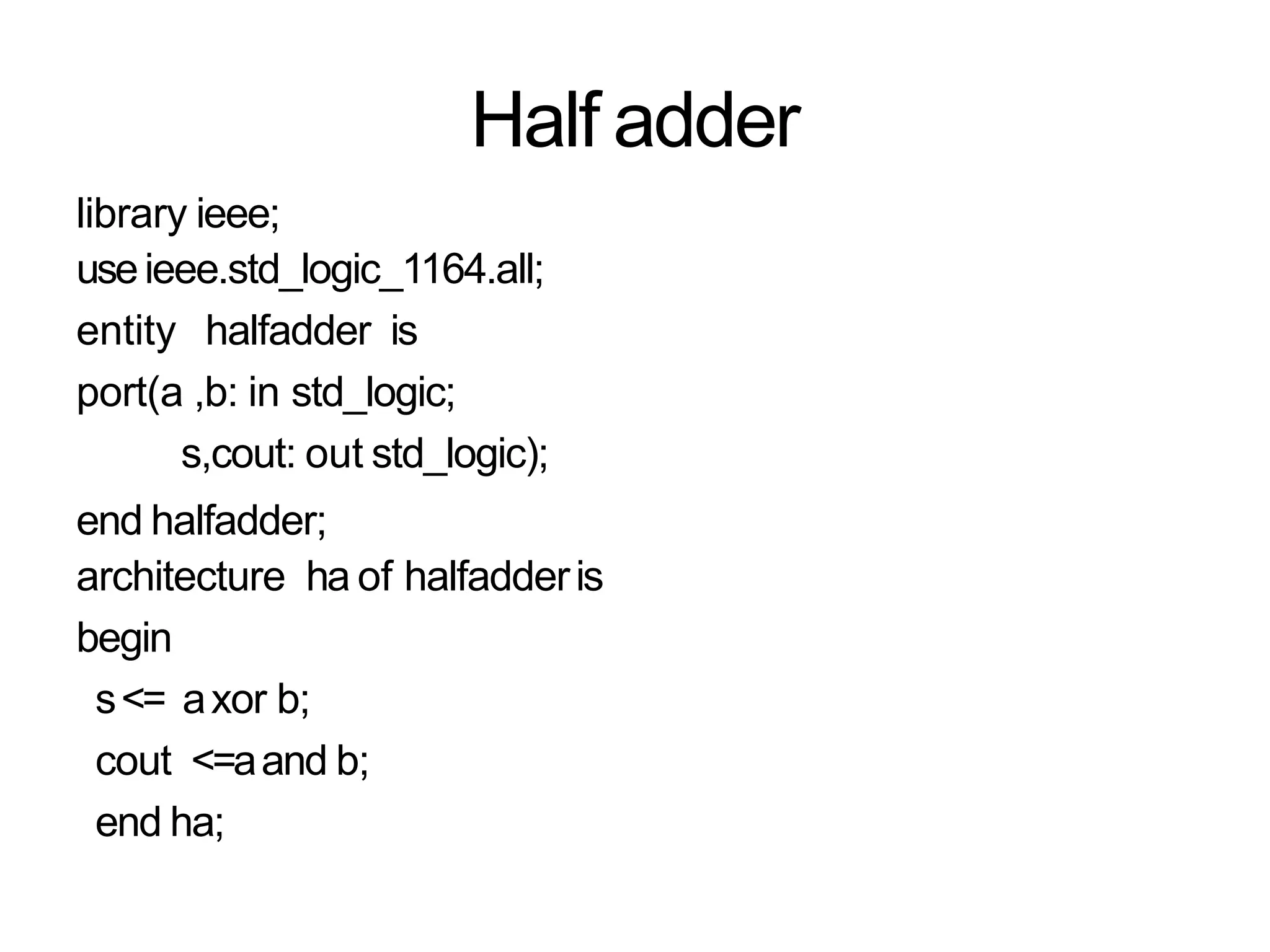
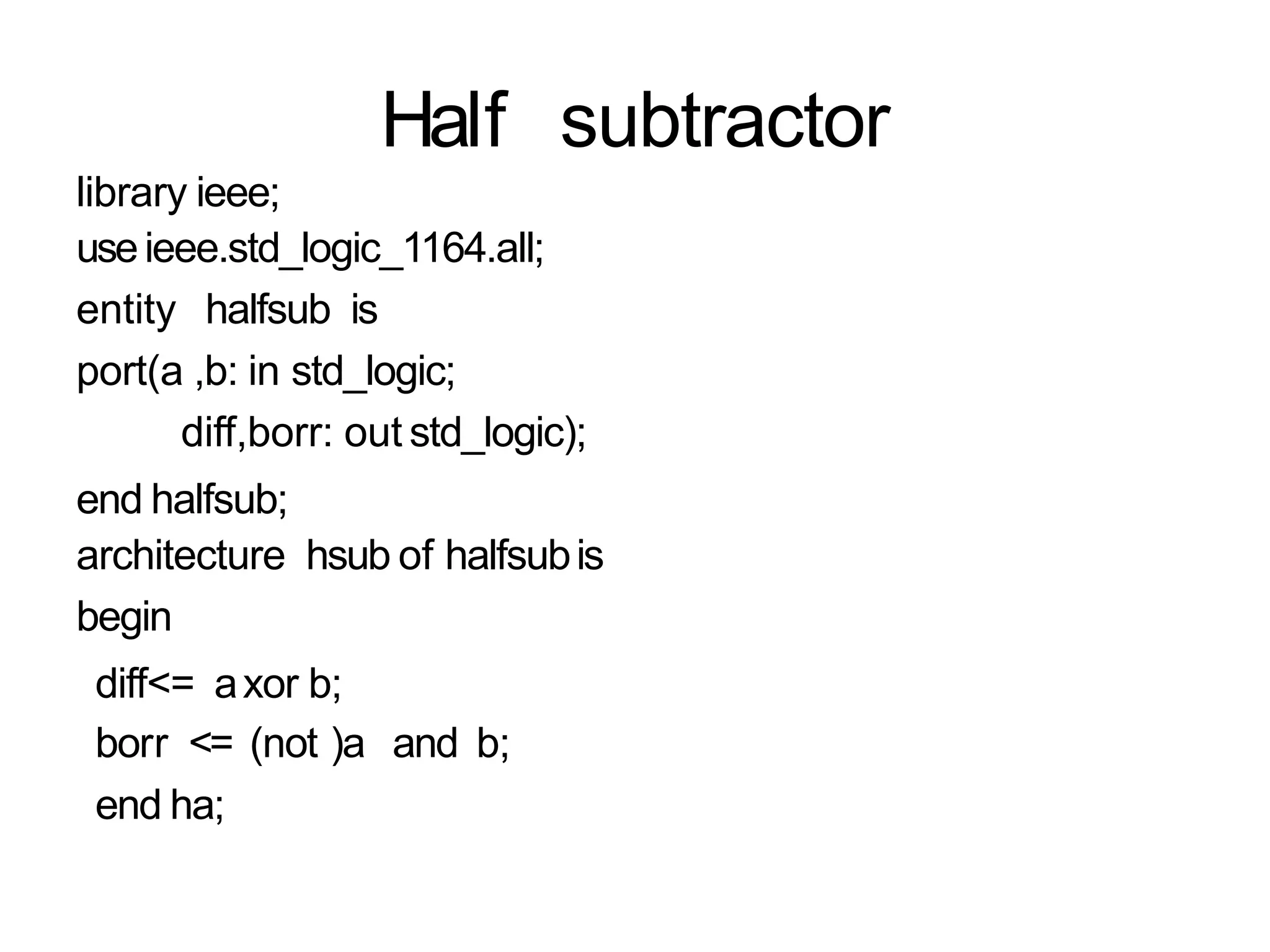
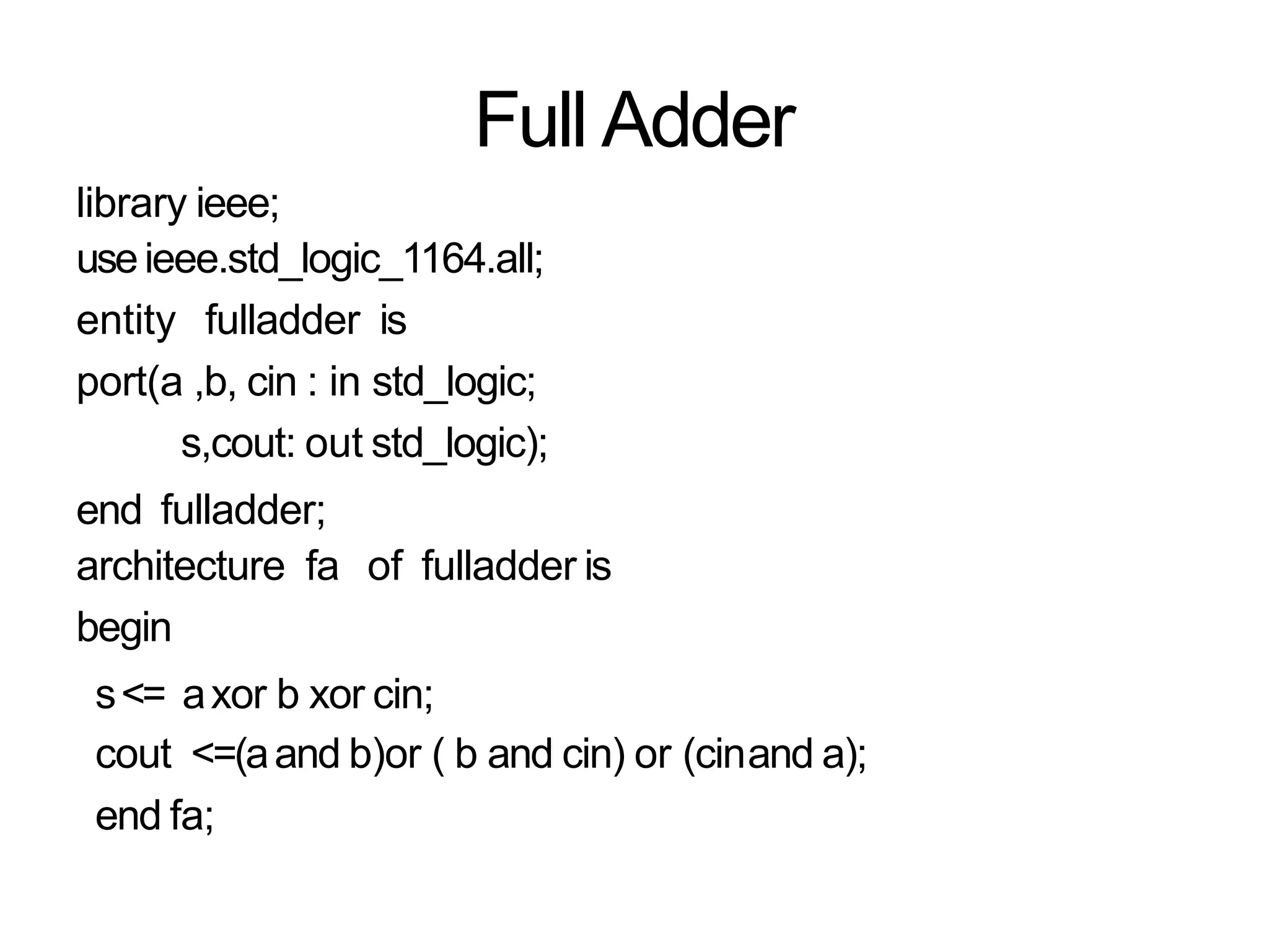
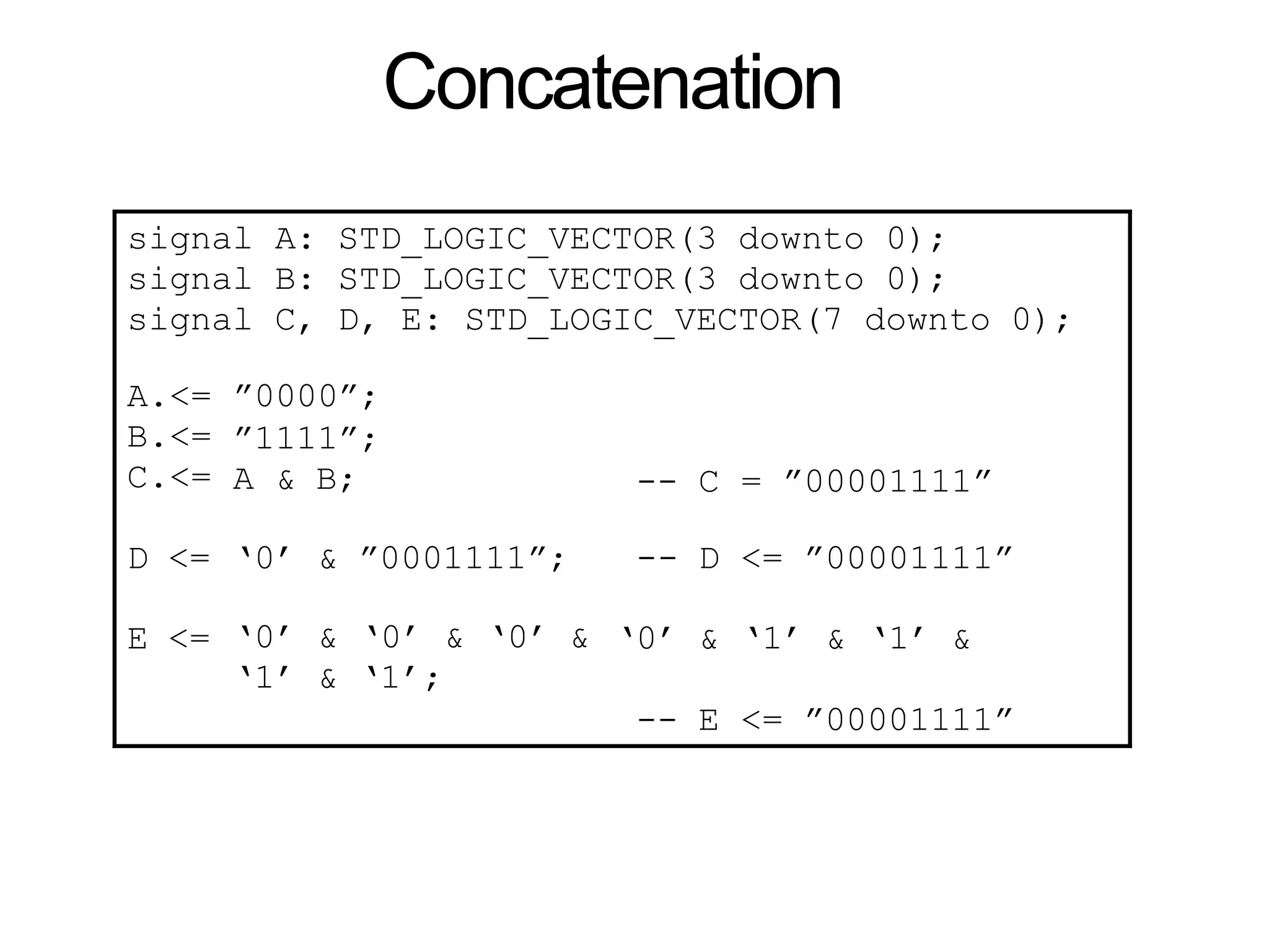
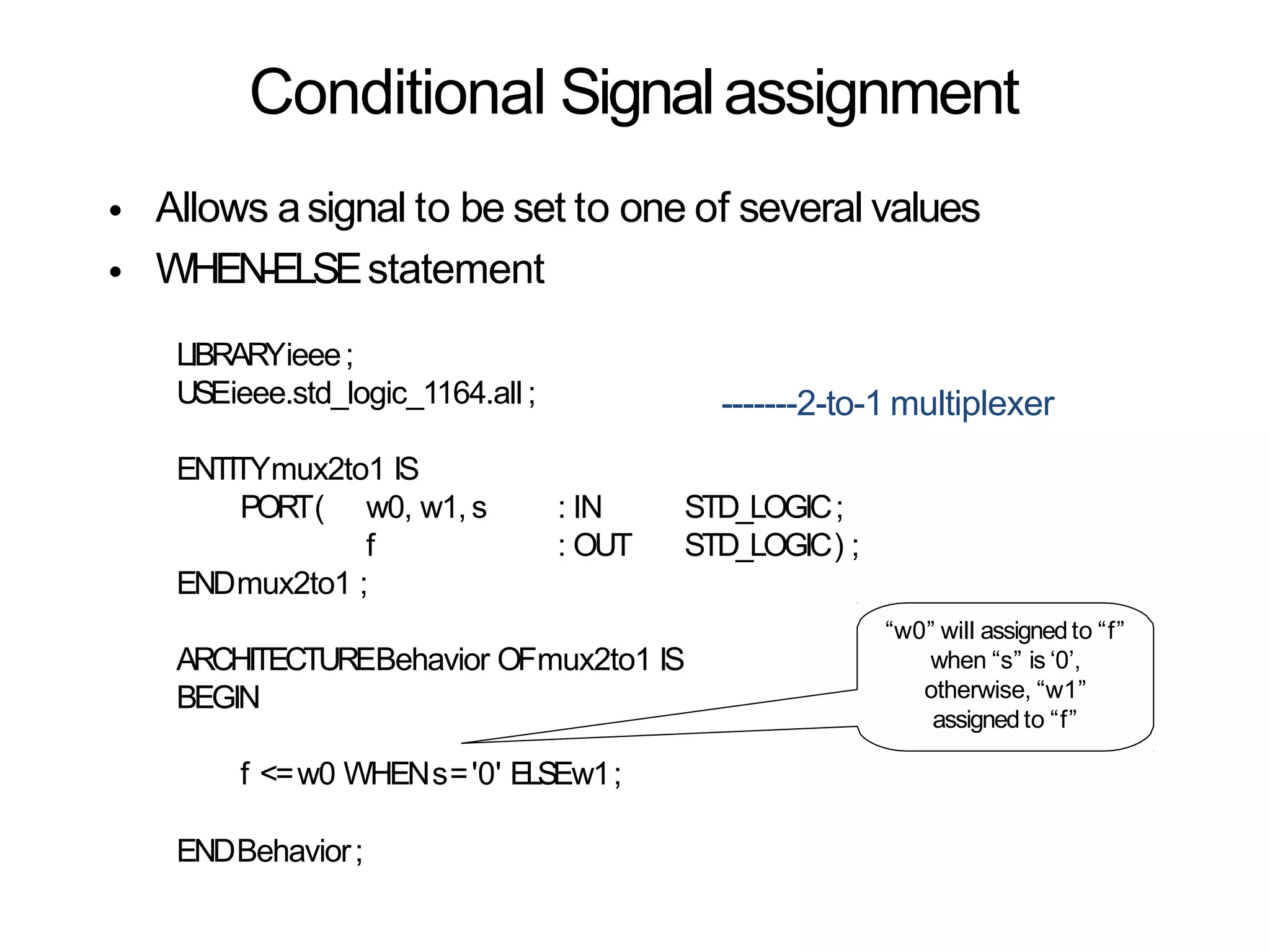
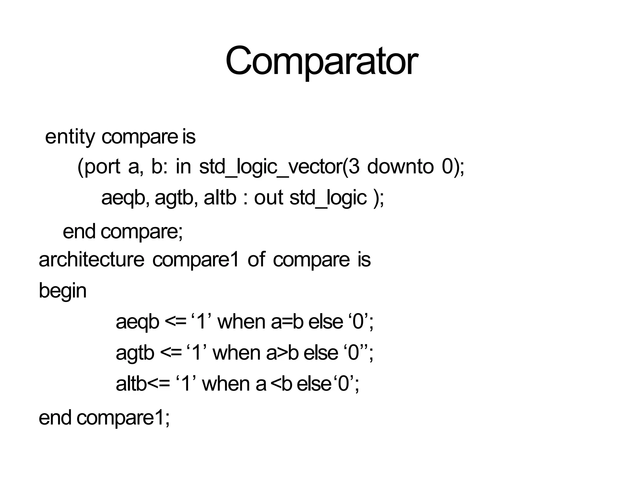
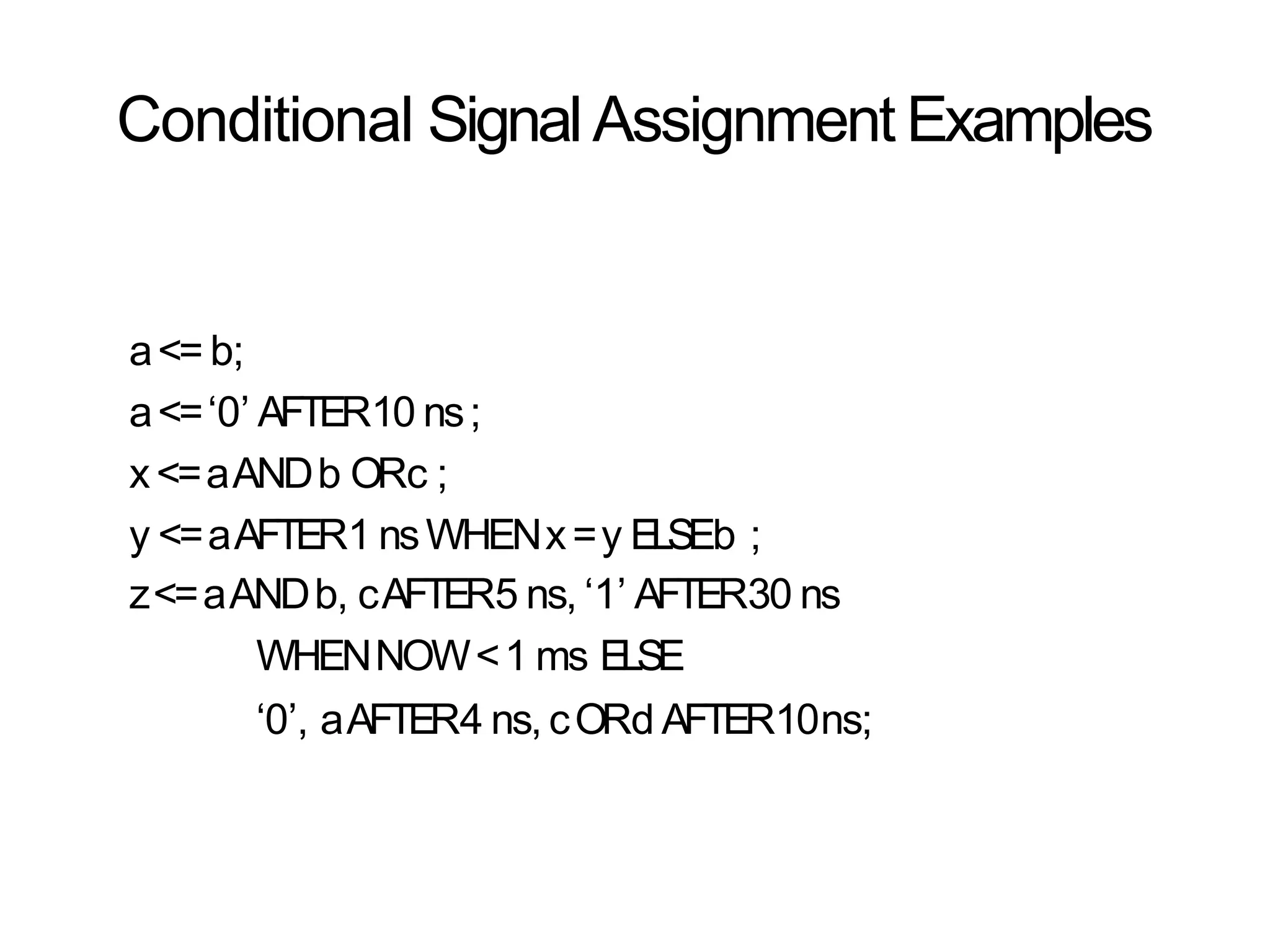
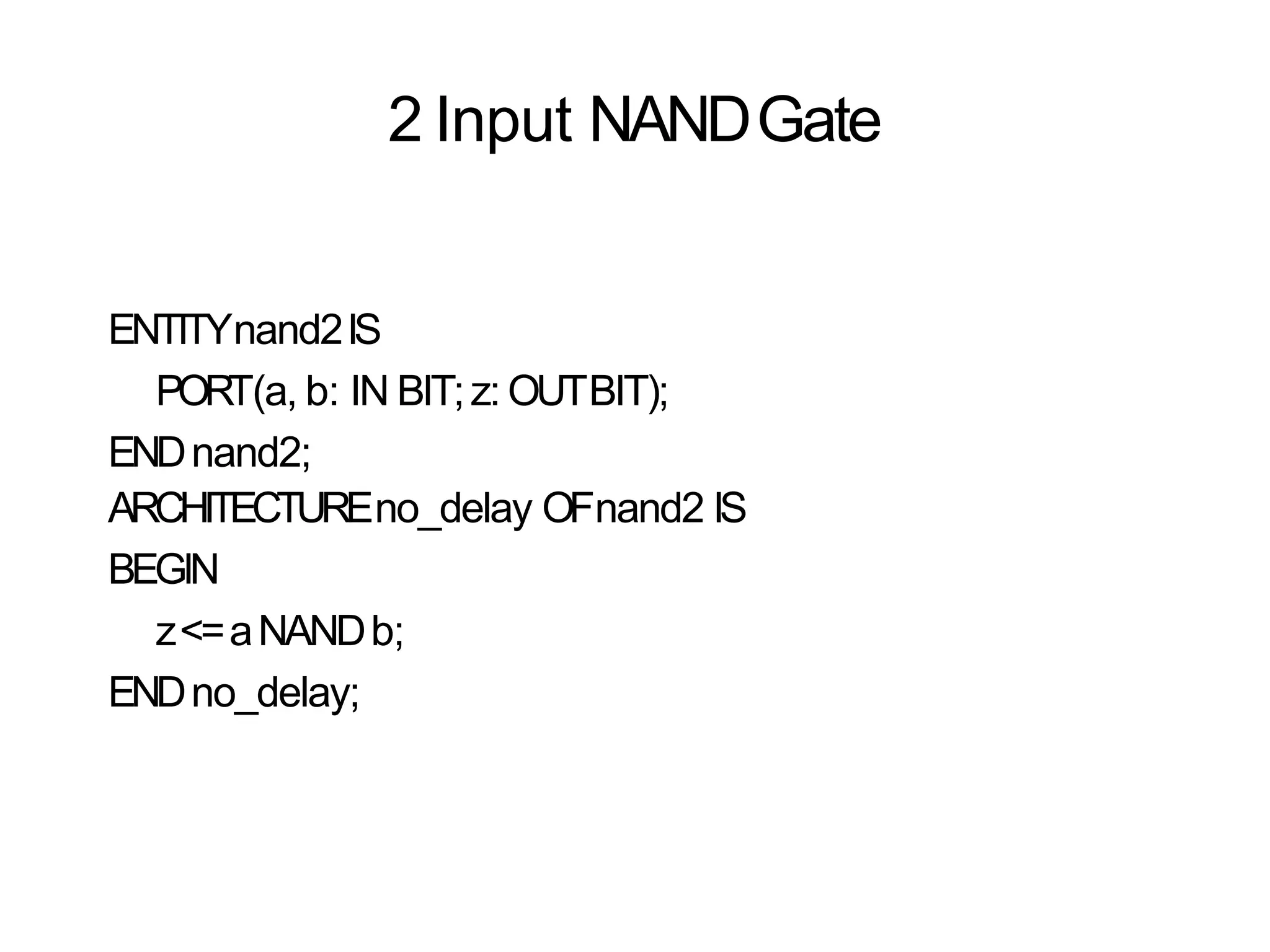
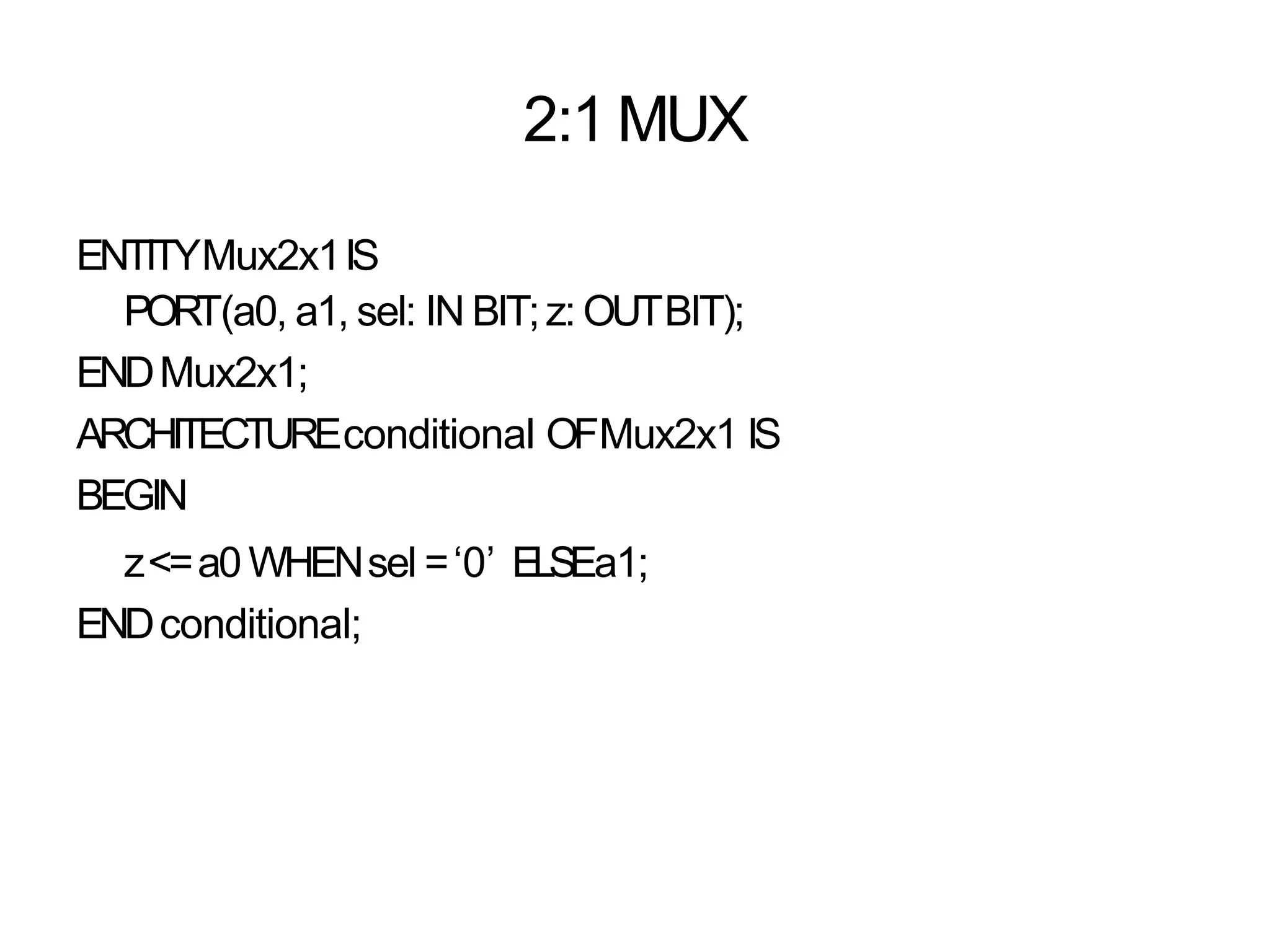
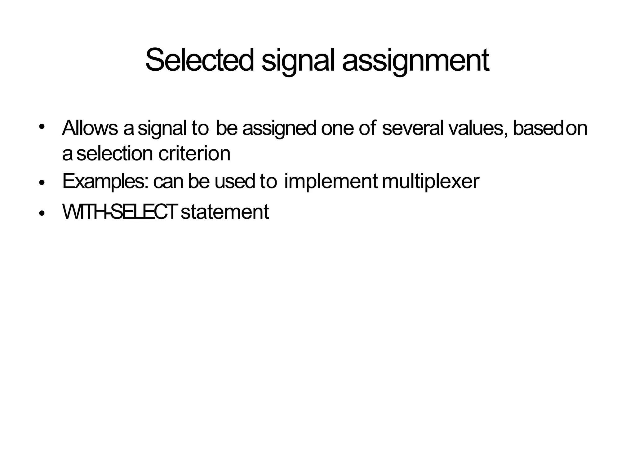
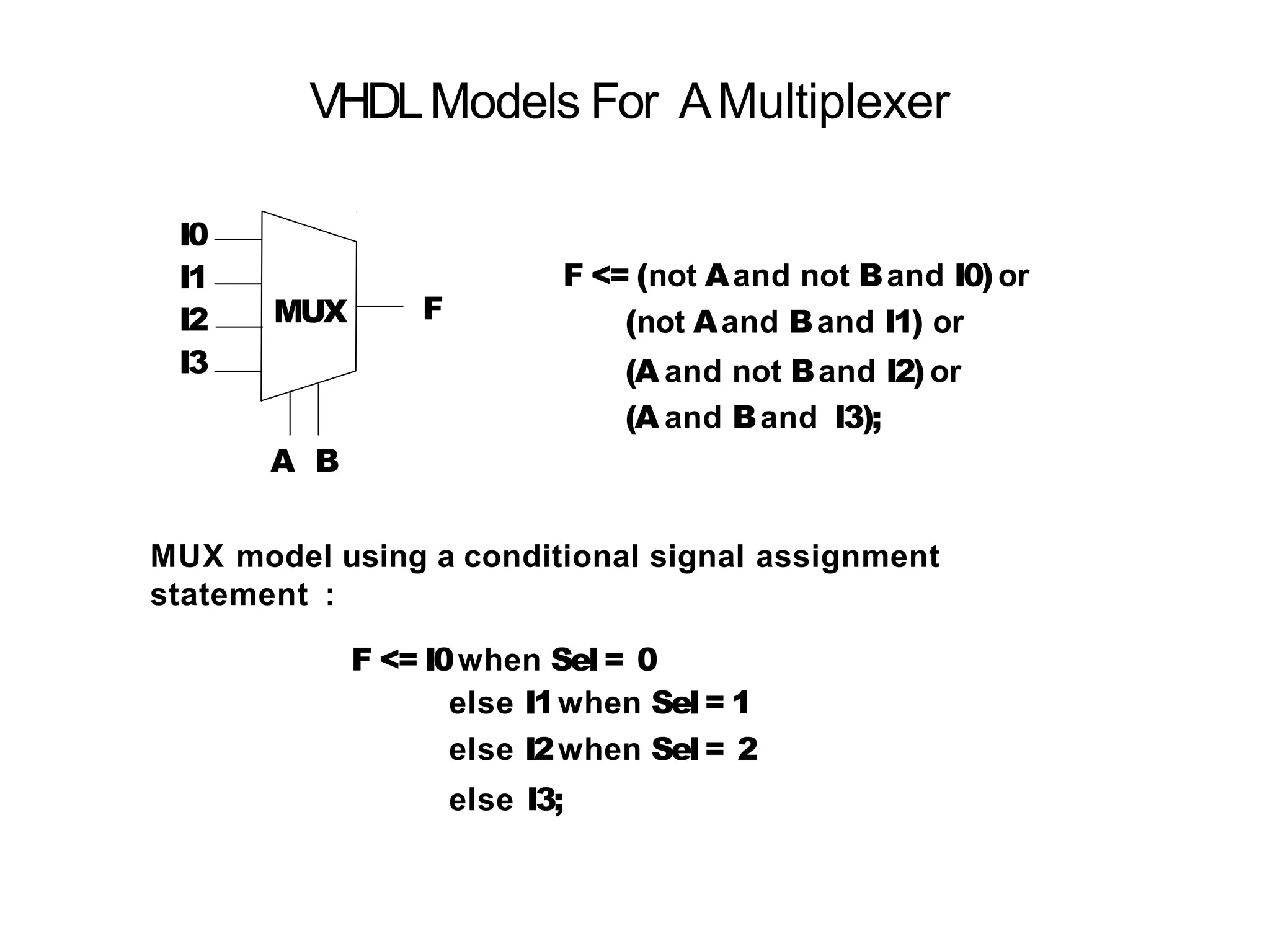
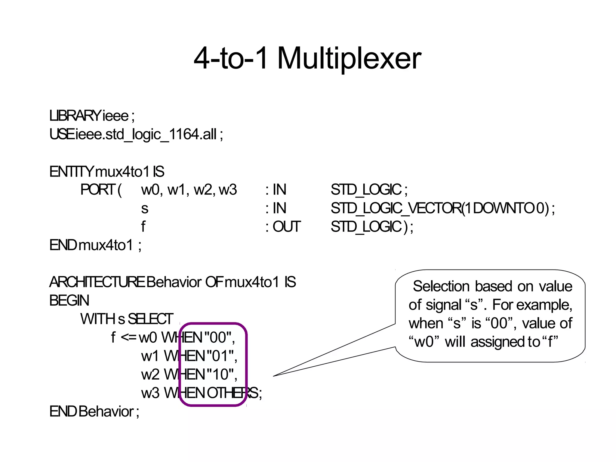
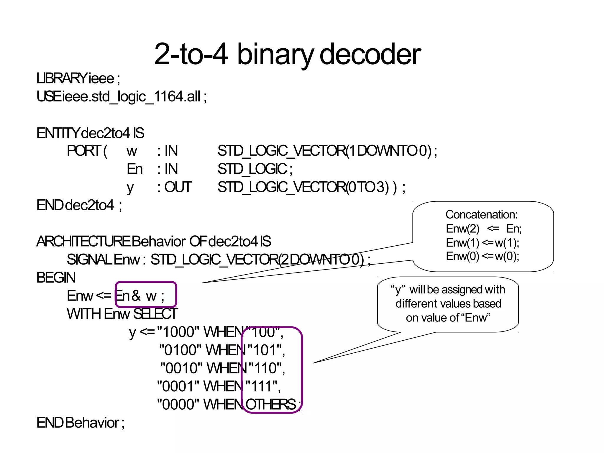
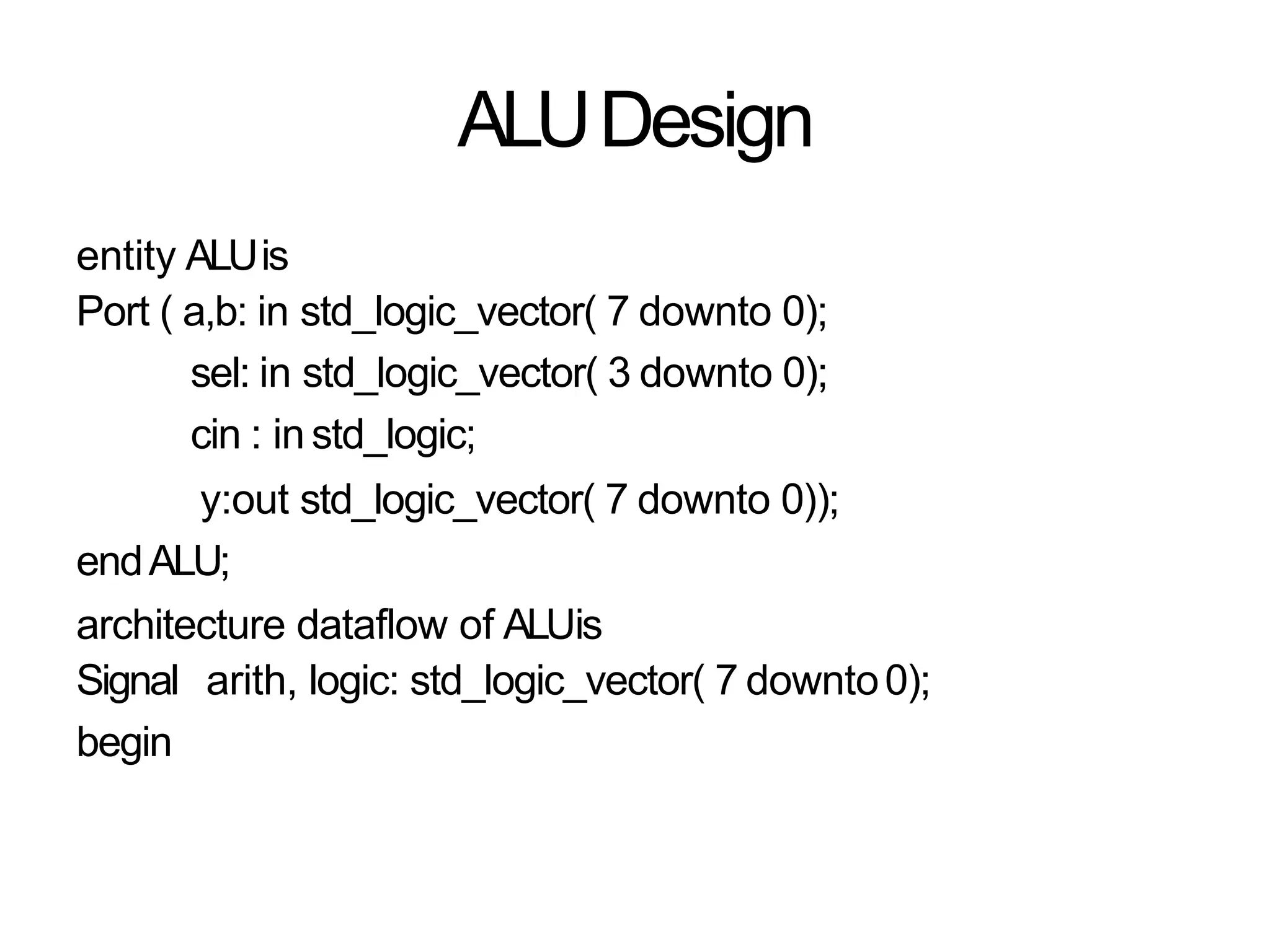
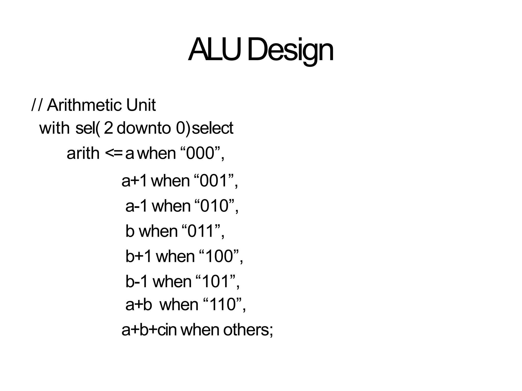
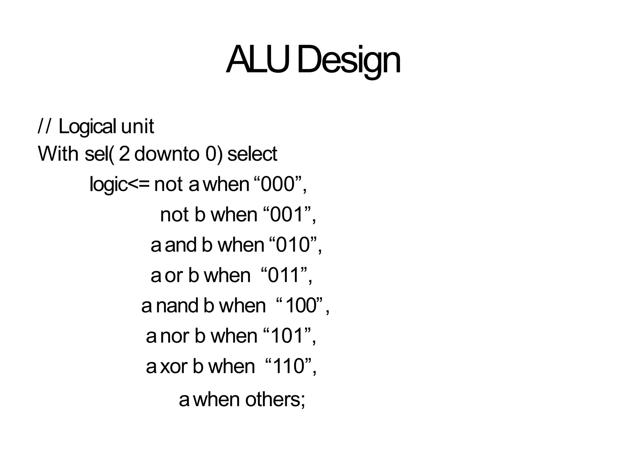
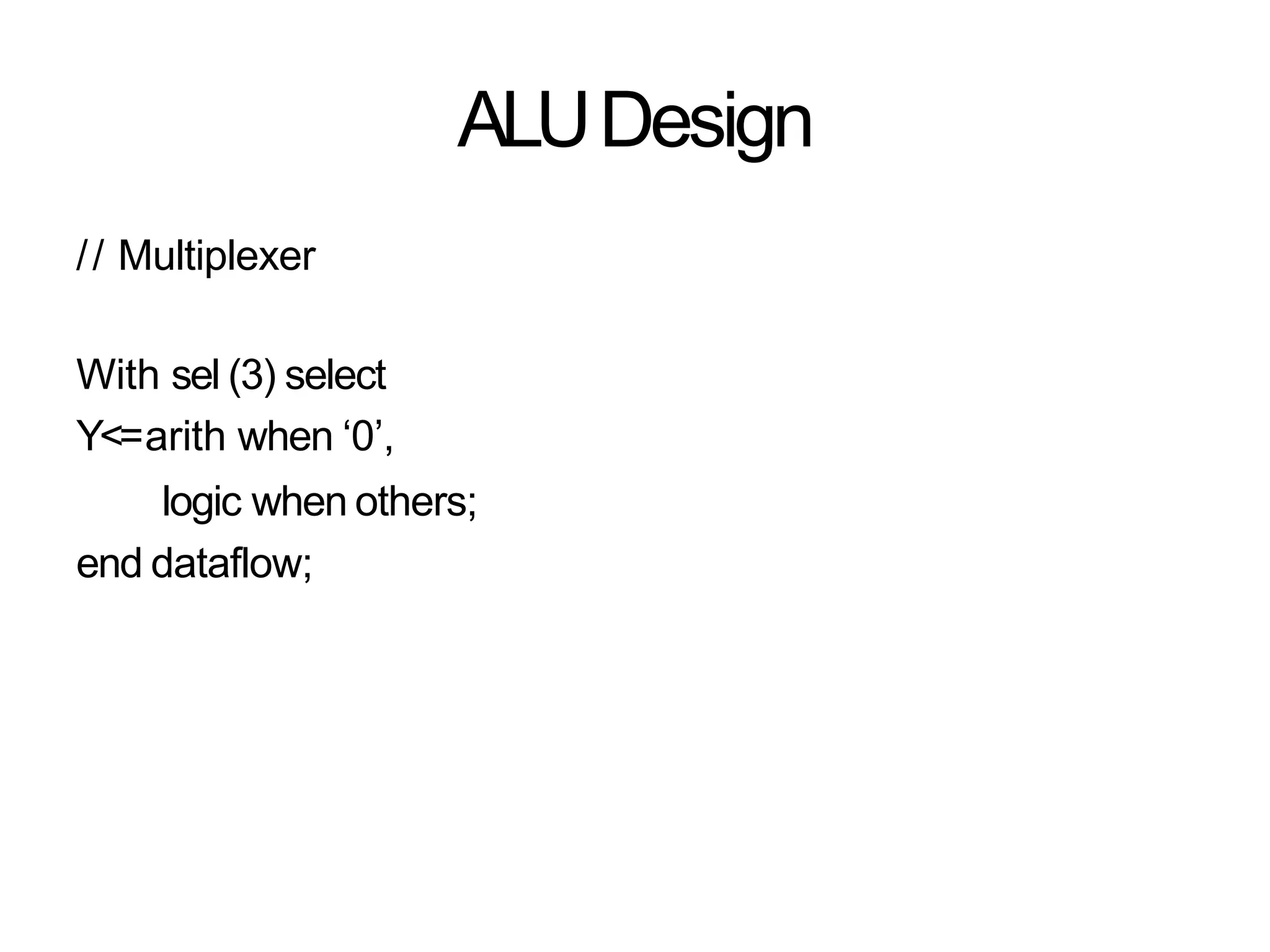
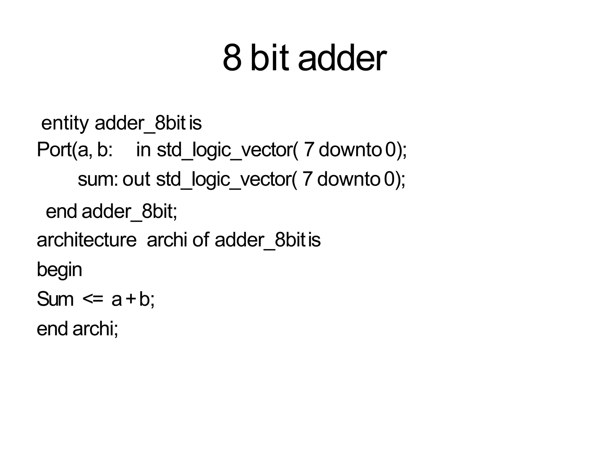
Data Flow Modeling in VHDL
PadmanabanK
Data Flow Modeling
• Adata flow style architecture models the hardware interms
of the movement of data over continuous time between
combinational logic components such asadders , decoders
and primitive logic gates.
It describes the Register Transfer Level behavior of a circuit.
It utilizes Logical and Relational Operators and Concurrent
assignment statements.
Thisstyle is not appropriate for modeling of sequentiallogic.
It is best applied in the modeling of data driven circuit
elements such asanArithmetic Logic Unit.
•
•
•
•
Half adder
library ieee;
useieee.std_logic_1164.all;
entity halfadder is
port(a ,b: in std_logic;
s,cout: out std_logic);
end halfadder;
architecture ha of halfadderis
begin
s<= axor b;
cout <=aand b;
end ha;
Half subtractor
library ieee;
useieee.std_logic_1164.all;
entity halfsub is
port(a ,b: in std_logic;
diff,borr: out std_logic);
end halfsub;
architecture hsub of halfsubis
begin
diff<= axor b;
borr <= (not )a and b;
end ha;
Full Adder
library ieee;
useieee.std_logic_1164.all;
entity fulladder is
port(a ,b, cin : in std_logic;
s,cout: out std_logic);
end fulladder;
architecture fa of fulladder is
begin
s<= axor b xor cin;
cout <=(aand b)or ( b and cin) or (cinand a);
end fa;
RulesFor Logical Operators
LogicOperators
• Logicoperators
• Logic operators precedence
and or nand nor xor not xnor
Highest
not
and or nand nor xor xnor
Lowest
Wanted: Y = ab +
cd
Incorrect
Y<=aand b or cand
d equivalent to
Y<=((a and b) or c) and
d equivalent to
Y=(ab + c)d
Correct
Y<=(a and b) or (c and d)
No Implied Precedence
Concatenation
signal A: STD_LOGIC_VECTOR(3 downto 0);
signal B: STD_LOGIC_VECTOR(3 downto 0);
signal C, D, E: STD_LOGIC_VECTOR(7 downto 0);
A.<=
B.<=
C.<=
”0000”;
”1111”;
A & B; -- C = ”00001111”
D <= ‘0’ & ”0001111”; -- D <= ”00001111”
E <= ‘0’ & ‘0’ & ‘0’ &
‘1’ & ‘1’;
‘0’
--
&
E
‘1’ & ‘1’ &
<= ”00001111”
Concurrent Signal AssignmentStatements
•
•
Functional Modeling Implements Simple CombinationalLogic
Concurrent SignalAssignment StatementsAre anAbbreviated
Form of Processes
– Conditional signal assignmentstatements
– SelectedSignalAssignment Statements
Conditional Signalassignment
•
•
Allows asignal to be set to one of several values
WHEN-ELSEstatement
-------2-to-1 multiplexer
LIBRARYieee;
USEieee.std_logic_1164.all ;
ENTITYmux2to1 IS
PORT( w0, w1, s
f
: IN STD_LOGIC;
: OUT STD_LOGIC) ;
ENDmux2to1 ;
ARCHITECTUREBehavior OFmux2to1 IS
BEGIN
f <=w0 WHENs='0' ELSEw1;
ENDBehavior;
“w0” will assignedto “f”
when “s” is ‘0’,
otherwise, “w1”
assignedto “f”
Comparator
entity compareis
(port a, b: in std_logic_vector(3 downto 0);
aeqb, agtb, altb : out std_logic );
end compare;
architecture compare1 of compare is
begin
aeqb <= ‘1’ when a=b else ‘0’;
agtb <= ‘1’ when a>b else ‘0’’;
altb<= ‘1’ when a<b else‘0’;
end compare1;
Conditional Signal Assignment Examples
a<= b;
a<=‘0’ AFTER10 ns;
x<=aANDb ORc ;
y <=aAFTER1 nsWHENx=y ELSEb ;
z<=aANDb, cAFTER5 ns, ‘1’ AFTER30 ns
WHENNOW<1 ms ELSE
‘0’, aAFTER4 ns, cORd AFTER10ns;
2 Input NANDGate
ENTITYnand2IS
PORT(a, b: IN BIT;z: OUTBIT);
ENDnand2;
ARCHITECTUREno_delay OFnand2 IS
BEGIN
z<=aNANDb;
ENDno_delay;
2:1 MUX
ENTITYMux2x1IS
PORT(a0, a1, sel: IN BIT;z: OUTBIT);
ENDMux2x1;
ARCHITECTUREconditional OFMux2x1 IS
BEGIN
z<=a0WHENsel =‘0’ ELSEa1;
ENDconditional;
Selected signal assignment
• Allows asignal to be assigned one of several values, basedon
aselection criterion
Examples: can be used to implement multiplexer
WITH-SELECTstatement
•
•
Selected Signal Assignment
WITHexpression SELECT
target <=selected_waveforms ;
selected_waveforms ::=
{ waveform WHENchoices,}
waveform WHENchoices
choices ::= choice { | choice }
choice ::= expression | range | simple_name | OTHERS
VHDLModels For AMultiplexer
F <= (not Aand not Band I0)or
(not Aand Band I1) or
(A and not Band I2) or
(A and Band I3);
A B
MUX model using a conditional signal assignment
statement :
F <= I0when Sel = 0
else I1when Sel= 1
else I2when Sel= 2
else I3;
MUX
I0
I1
I2
I3
F
4-to-1 Multiplexer
LIBRARYieee;
USEieee.std_logic_1164.all ;
ENTITYmux4to1IS
PORT( w0, w1, w2, w3 : IN STD_LOGIC;
s : IN STD_LOGIC_VECTOR(1DOWNTO0);
f : OUT STD_LOGIC);
ENDmux4to1 ;
ARCHITECTUREBehavior OFmux4to1 IS
BEGIN
WITHsSELECT
f <=w0 WHEN"00",
w1 WHEN"01",
w2 WHEN"10",
w3 WHENOTHERS;
ENDBehavior;
Selection based on value
of signal “s”. For example,
when “s” is “00”, value of
“w0” will assignedto“f”
2-to-4 binarydecoder
LIBRARYieee;
USEieee.std_logic_1164.all ;
ENTITYdec2to4IS
PORT( w : IN STD_LOGIC_VECTOR(1DOWNTO0);
En : IN STD_LOGIC;
y : OUT STD_LOGIC_VECTOR(0TO3) ) ;
ENDdec2to4 ;
ARCHITECTUREBehavior OFdec2to4IS
SIGNALEnw: STD_LOGIC_VECTOR(2DOWNTO0) ;
BEGIN
Enw<=En& w ;
WITHEnw SELECT
y <="1000" WHEN"100",
"0100" WHEN"101",
"0010" WHEN"110",
"0001" WHEN"111",
"0000" WHENOTHERS;
ENDBehavior;
“y” willbe assignedwith
different values based
on value of“Enw”
Concatenation:
Enw(2) <= En;
Enw(1) <=w(1);
Enw(0) <=w(0);
ALUDesign
entity ALUis
Port ( a,b: in std_logic_vector( 7 downto 0);
sel: in std_logic_vector( 3 downto 0);
cin : in std_logic;
y:out std_logic_vector( 7 downto 0));
endALU;
architecture dataflow of ALUis
Signal arith, logic: std_logic_vector( 7 downto0);
begin
ALUDesign
// Arithmetic Unit
with sel( 2 downto 0)select
arith <=awhen “000”,
a+1when “001”,
a-1 when “010”,
b when “011”,
b+1 when “100”,
b-1 when “101”,
a+b when “110”,
a+b+cin when others;
ALUDesign
// Logical unit
With sel( 2 downto 0) select
logic<= not awhen “000”,
not b when “001”,
aand b when “010”,
aor b when “011”,
anand b when “100”,
anor b when “101”,
axor b when “110”,
awhen others;
ALUDesign
// Multiplexer
With sel (3) select
Y<=arith when ‘0’,
logic when others;
end dataflow;
8 bit adder
entity adder_8bitis
Port(a, b: in std_logic_vector( 7 downto0);
sum: out std_logic_vector( 7 downto0);
end adder_8bit;
architecture archi of adder_8bitis
begin
Sum <= a+b;
end archi;

Vhdl

  • 1.
    Data Flow Modelingin VHDL PadmanabanK
  • 2.
    Data Flow Modeling •Adata flow style architecture models the hardware interms of the movement of data over continuous time between combinational logic components such asadders , decoders and primitive logic gates. It describes the Register Transfer Level behavior of a circuit. It utilizes Logical and Relational Operators and Concurrent assignment statements. Thisstyle is not appropriate for modeling of sequentiallogic. It is best applied in the modeling of data driven circuit elements such asanArithmetic Logic Unit. • • • •
  • 3.
    Half adder library ieee; useieee.std_logic_1164.all; entityhalfadder is port(a ,b: in std_logic; s,cout: out std_logic); end halfadder; architecture ha of halfadderis begin s<= axor b; cout <=aand b; end ha;
  • 4.
    Half subtractor library ieee; useieee.std_logic_1164.all; entityhalfsub is port(a ,b: in std_logic; diff,borr: out std_logic); end halfsub; architecture hsub of halfsubis begin diff<= axor b; borr <= (not )a and b; end ha;
  • 5.
    Full Adder library ieee; useieee.std_logic_1164.all; entityfulladder is port(a ,b, cin : in std_logic; s,cout: out std_logic); end fulladder; architecture fa of fulladder is begin s<= axor b xor cin; cout <=(aand b)or ( b and cin) or (cinand a); end fa;
  • 6.
  • 7.
    LogicOperators • Logicoperators • Logicoperators precedence and or nand nor xor not xnor Highest not and or nand nor xor xnor Lowest
  • 8.
    Wanted: Y =ab + cd Incorrect Y<=aand b or cand d equivalent to Y<=((a and b) or c) and d equivalent to Y=(ab + c)d Correct Y<=(a and b) or (c and d) No Implied Precedence
  • 9.
    Concatenation signal A: STD_LOGIC_VECTOR(3downto 0); signal B: STD_LOGIC_VECTOR(3 downto 0); signal C, D, E: STD_LOGIC_VECTOR(7 downto 0); A.<= B.<= C.<= ”0000”; ”1111”; A & B; -- C = ”00001111” D <= ‘0’ & ”0001111”; -- D <= ”00001111” E <= ‘0’ & ‘0’ & ‘0’ & ‘1’ & ‘1’; ‘0’ -- & E ‘1’ & ‘1’ & <= ”00001111”
  • 10.
    Concurrent Signal AssignmentStatements • • FunctionalModeling Implements Simple CombinationalLogic Concurrent SignalAssignment StatementsAre anAbbreviated Form of Processes – Conditional signal assignmentstatements – SelectedSignalAssignment Statements
  • 11.
    Conditional Signalassignment • • Allows asignalto be set to one of several values WHEN-ELSEstatement -------2-to-1 multiplexer LIBRARYieee; USEieee.std_logic_1164.all ; ENTITYmux2to1 IS PORT( w0, w1, s f : IN STD_LOGIC; : OUT STD_LOGIC) ; ENDmux2to1 ; ARCHITECTUREBehavior OFmux2to1 IS BEGIN f <=w0 WHENs='0' ELSEw1; ENDBehavior; “w0” will assignedto “f” when “s” is ‘0’, otherwise, “w1” assignedto “f”
  • 12.
    Comparator entity compareis (port a,b: in std_logic_vector(3 downto 0); aeqb, agtb, altb : out std_logic ); end compare; architecture compare1 of compare is begin aeqb <= ‘1’ when a=b else ‘0’; agtb <= ‘1’ when a>b else ‘0’’; altb<= ‘1’ when a<b else‘0’; end compare1;
  • 13.
    Conditional Signal AssignmentExamples a<= b; a<=‘0’ AFTER10 ns; x<=aANDb ORc ; y <=aAFTER1 nsWHENx=y ELSEb ; z<=aANDb, cAFTER5 ns, ‘1’ AFTER30 ns WHENNOW<1 ms ELSE ‘0’, aAFTER4 ns, cORd AFTER10ns;
  • 14.
    2 Input NANDGate ENTITYnand2IS PORT(a,b: IN BIT;z: OUTBIT); ENDnand2; ARCHITECTUREno_delay OFnand2 IS BEGIN z<=aNANDb; ENDno_delay;
  • 15.
    2:1 MUX ENTITYMux2x1IS PORT(a0, a1,sel: IN BIT;z: OUTBIT); ENDMux2x1; ARCHITECTUREconditional OFMux2x1 IS BEGIN z<=a0WHENsel =‘0’ ELSEa1; ENDconditional;
  • 16.
    Selected signal assignment •Allows asignal to be assigned one of several values, basedon aselection criterion Examples: can be used to implement multiplexer WITH-SELECTstatement • •
  • 17.
    Selected Signal Assignment WITHexpressionSELECT target <=selected_waveforms ; selected_waveforms ::= { waveform WHENchoices,} waveform WHENchoices choices ::= choice { | choice } choice ::= expression | range | simple_name | OTHERS
  • 18.
    VHDLModels For AMultiplexer F<= (not Aand not Band I0)or (not Aand Band I1) or (A and not Band I2) or (A and Band I3); A B MUX model using a conditional signal assignment statement : F <= I0when Sel = 0 else I1when Sel= 1 else I2when Sel= 2 else I3; MUX I0 I1 I2 I3 F
  • 19.
    4-to-1 Multiplexer LIBRARYieee; USEieee.std_logic_1164.all ; ENTITYmux4to1IS PORT(w0, w1, w2, w3 : IN STD_LOGIC; s : IN STD_LOGIC_VECTOR(1DOWNTO0); f : OUT STD_LOGIC); ENDmux4to1 ; ARCHITECTUREBehavior OFmux4to1 IS BEGIN WITHsSELECT f <=w0 WHEN"00", w1 WHEN"01", w2 WHEN"10", w3 WHENOTHERS; ENDBehavior; Selection based on value of signal “s”. For example, when “s” is “00”, value of “w0” will assignedto“f”
  • 20.
    2-to-4 binarydecoder LIBRARYieee; USEieee.std_logic_1164.all ; ENTITYdec2to4IS PORT(w : IN STD_LOGIC_VECTOR(1DOWNTO0); En : IN STD_LOGIC; y : OUT STD_LOGIC_VECTOR(0TO3) ) ; ENDdec2to4 ; ARCHITECTUREBehavior OFdec2to4IS SIGNALEnw: STD_LOGIC_VECTOR(2DOWNTO0) ; BEGIN Enw<=En& w ; WITHEnw SELECT y <="1000" WHEN"100", "0100" WHEN"101", "0010" WHEN"110", "0001" WHEN"111", "0000" WHENOTHERS; ENDBehavior; “y” willbe assignedwith different values based on value of“Enw” Concatenation: Enw(2) <= En; Enw(1) <=w(1); Enw(0) <=w(0);
  • 21.
    ALUDesign entity ALUis Port (a,b: in std_logic_vector( 7 downto 0); sel: in std_logic_vector( 3 downto 0); cin : in std_logic; y:out std_logic_vector( 7 downto 0)); endALU; architecture dataflow of ALUis Signal arith, logic: std_logic_vector( 7 downto0); begin
  • 22.
    ALUDesign // Arithmetic Unit withsel( 2 downto 0)select arith <=awhen “000”, a+1when “001”, a-1 when “010”, b when “011”, b+1 when “100”, b-1 when “101”, a+b when “110”, a+b+cin when others;
  • 23.
    ALUDesign // Logical unit Withsel( 2 downto 0) select logic<= not awhen “000”, not b when “001”, aand b when “010”, aor b when “011”, anand b when “100”, anor b when “101”, axor b when “110”, awhen others;
  • 24.
    ALUDesign // Multiplexer With sel(3) select Y<=arith when ‘0’, logic when others; end dataflow;
  • 25.
    8 bit adder entityadder_8bitis Port(a, b: in std_logic_vector( 7 downto0); sum: out std_logic_vector( 7 downto0); end adder_8bit; architecture archi of adder_8bitis begin Sum <= a+b; end archi;