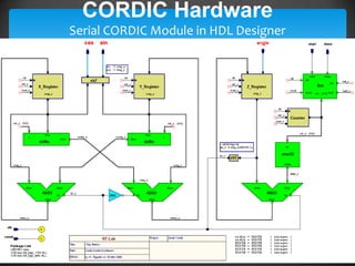
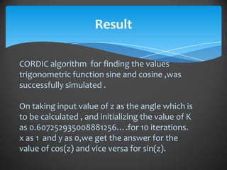
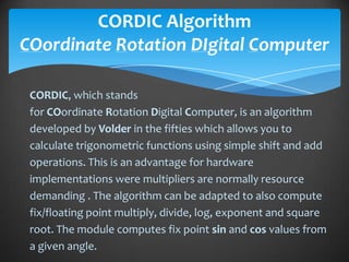
The document discusses a project focused on the implementation of the CORDIC algorithm for calculating trigonometric functions using VHDL in digital circuit design. It outlines the history and basics of VHDL, the structure of design units, and details the CORDIC algorithm's operation, including its iterations and applications in computing sine and cosine values. The conclusion emphasizes the algorithm's efficiency in hardware implementations despite not being the fastest for multiplications or logarithmic calculations.


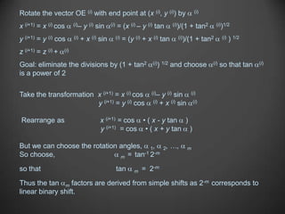
![Whereas a real rotation does not change the length R(i) of the vector, a
pseudorotation step increases its length to:
R(i+1) = R(i) (1 + tan2 (i))1/2
The coordinates of the new end point E (i+1) after pseudorotation is derived
by multiplying the coordinates of E(i+1) by the expansion factor
x (i+1) = x (i) – y (i) tan (i)
y (i+1) = y (i) + x (i) tan (i) [Pseudorotation]
z (i+1) = z (i) + (i)
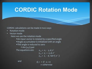
Now the ith step, calculating (xi+1, yi+1) from (xi, yi)
can be written
xi+1 = Ki ( xi - yi di 2-i )
yi+1 = Ki ( yi - xi di 2-i )
1
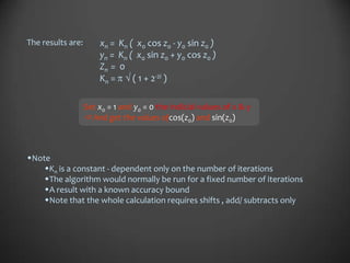
Where Ki = cos( tan-1 2-i ) =
( 1 + 2-2i )
And di = 1
which is determined by the direction of the necessary correction
Now the product, Ki = ( ( 1 + 2-2i )-1 0.6073
is a constant depending on the number of iterations](https://image.slidesharecdn.com/vhdlcordicsr-120812235210-phpapp02/85/VHDL-and-Cordic-Algorithim-14-320.jpg)
![Basic CORDIC Iterations
Pick (i) such that tan (i) = di 2 –i, di Î {–1, 1}
x(i+1) = x(i) – di y(i)2–i
y (i+1) = y (i) + di x(i)2–I [CORDIC iteration]
z (i+1) = z (i) – di tan–1 2–i
If we always pseudo rotate by the same set of angles
(with + or – signs), then the expansion factor K is a
constant that can be pre-computed
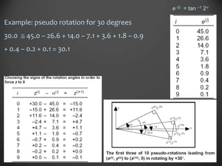
e (i) = tan –1 2-i](https://image.slidesharecdn.com/vhdlcordicsr-120812235210-phpapp02/85/VHDL-and-Cordic-Algorithim-15-320.jpg)