Download to read offline
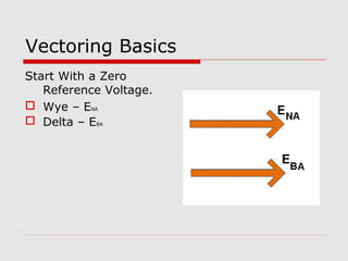
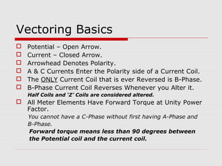
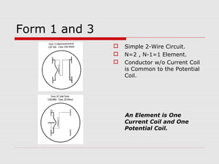
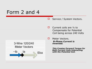
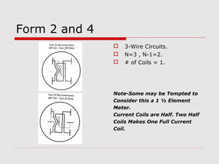
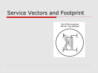
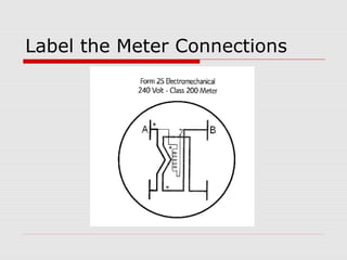
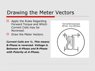
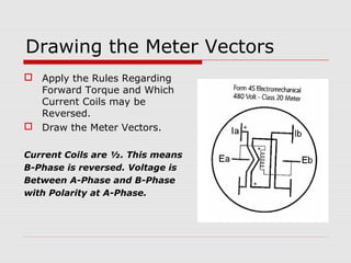
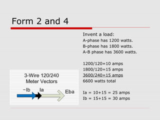
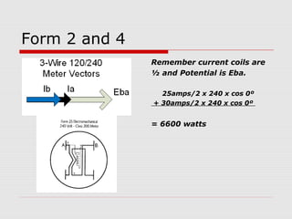
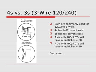

This document provides an overview of vectoring basics for electricity meters. It discusses the different meter forms, including forms 1 and 3 which have one element and conforming vectors, and forms 2 and 4 which have one element but non-conforming vectors where the B-phase current coil is reversed. The document outlines the steps for drawing meter vectors, including applying rules about forward torque and reversed current coils. It provides an example of drawing vectors for a form 2 meter with a hypothetical 3-wire load.


![Incomplete PPT on first topic.pptx [Autosaved] [Autosaved].ppt](https://cdn.slidesharecdn.com/ss_thumbnails/incompletepptonfirsttopic-230311215449-64eb2ec5-thumbnail.jpg?width=640&height=640&fit=bounds)


