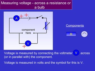
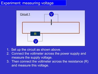
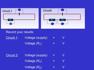
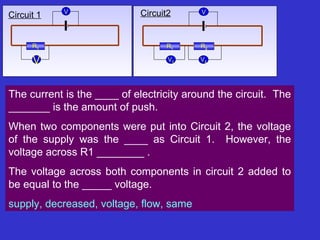
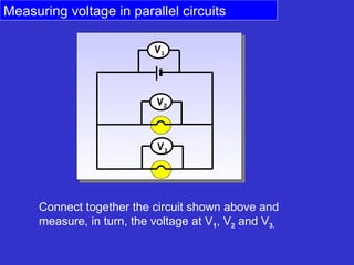
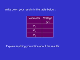
A V component here R Voltage is measured by connecting the voltmeter  across   (or in parallel with )  the component. Voltage is measured in volts and the symbol for this is V. V Components Measuring voltage -  across a resistance or a bulb
1.  Set up the circuit as shown above. Connect the voltmeter across the power supply and measure the supply voltage.  3. Then connect the voltmeter across the resistance (R) and measure this voltage. Experiment: measuring voltage R V V Circuit 1
Add another resistance ( R 2 ) to the circuit as shown. Connect the voltmeter across the power supply and measure the supply voltage.  Then measure the voltage across each of the resistances. R 1 R 2 V V 1 V 2 Circuit 2 Experiment: measuring voltage
Record your results: Circuit 1 :  Voltage (supply)  = V Voltage (R 1 ) =  V Circuit 2 : Voltage (supply) = V Voltage (R 1 )   =  V Voltage (R 2 ) = V R 1 R 2 V V 1 V 2 R 1 V V Circuit 1 Circuit2
The current is the ____ of electricity around the circuit.  The _______ is the amount of push. When two components were put into Circuit 2, the voltage of the supply was the ____ as Circuit 1.  However, the voltage across R1 ________ .  The voltage across both components in circuit 2 added to be equal to the _____ voltage. supply, decreased, voltage, flow, same   Circuit2 Circuit2 R 1 R 2 V V 1 V 2 R 1 V V Circuit 1
Measuring voltage in parallel circuits Connect together the circuit shown above and measure, in turn, the voltage at V 1 , V 2  and V 3.   V 1 V 2 V 3
Write down your results in the table below : Explain anything you notice about the results. V 3 V 2 V 1 Voltage (V) Voltmeter
Parallel and series circuits

Measuring Voltage

  • 1.
    A V componenthere R Voltage is measured by connecting the voltmeter across (or in parallel with ) the component. Voltage is measured in volts and the symbol for this is V. V Components Measuring voltage - across a resistance or a bulb
  • 2.
    1. Setup the circuit as shown above. Connect the voltmeter across the power supply and measure the supply voltage. 3. Then connect the voltmeter across the resistance (R) and measure this voltage. Experiment: measuring voltage R V V Circuit 1
  • 3.
    Add another resistance( R 2 ) to the circuit as shown. Connect the voltmeter across the power supply and measure the supply voltage. Then measure the voltage across each of the resistances. R 1 R 2 V V 1 V 2 Circuit 2 Experiment: measuring voltage
  • 4.
    Record your results:Circuit 1 : Voltage (supply) = V Voltage (R 1 ) = V Circuit 2 : Voltage (supply) = V Voltage (R 1 ) = V Voltage (R 2 ) = V R 1 R 2 V V 1 V 2 R 1 V V Circuit 1 Circuit2
  • 5.
    The current isthe ____ of electricity around the circuit. The _______ is the amount of push. When two components were put into Circuit 2, the voltage of the supply was the ____ as Circuit 1. However, the voltage across R1 ________ . The voltage across both components in circuit 2 added to be equal to the _____ voltage. supply, decreased, voltage, flow, same Circuit2 Circuit2 R 1 R 2 V V 1 V 2 R 1 V V Circuit 1
  • 6.
    Measuring voltage inparallel circuits Connect together the circuit shown above and measure, in turn, the voltage at V 1 , V 2 and V 3. V 1 V 2 V 3
  • 7.
    Write down yourresults in the table below : Explain anything you notice about the results. V 3 V 2 V 1 Voltage (V) Voltmeter
  • 8.