Download to read offline
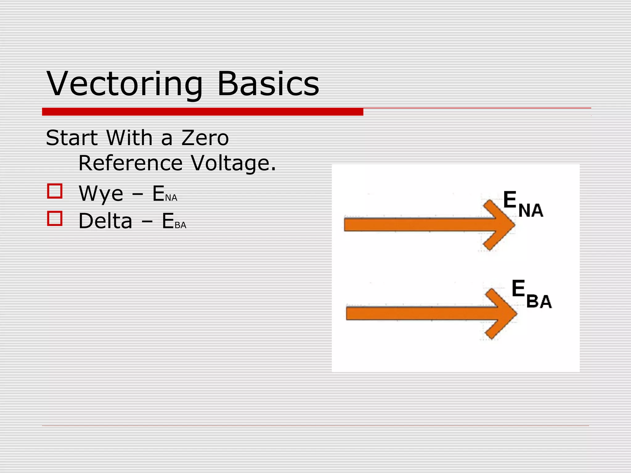
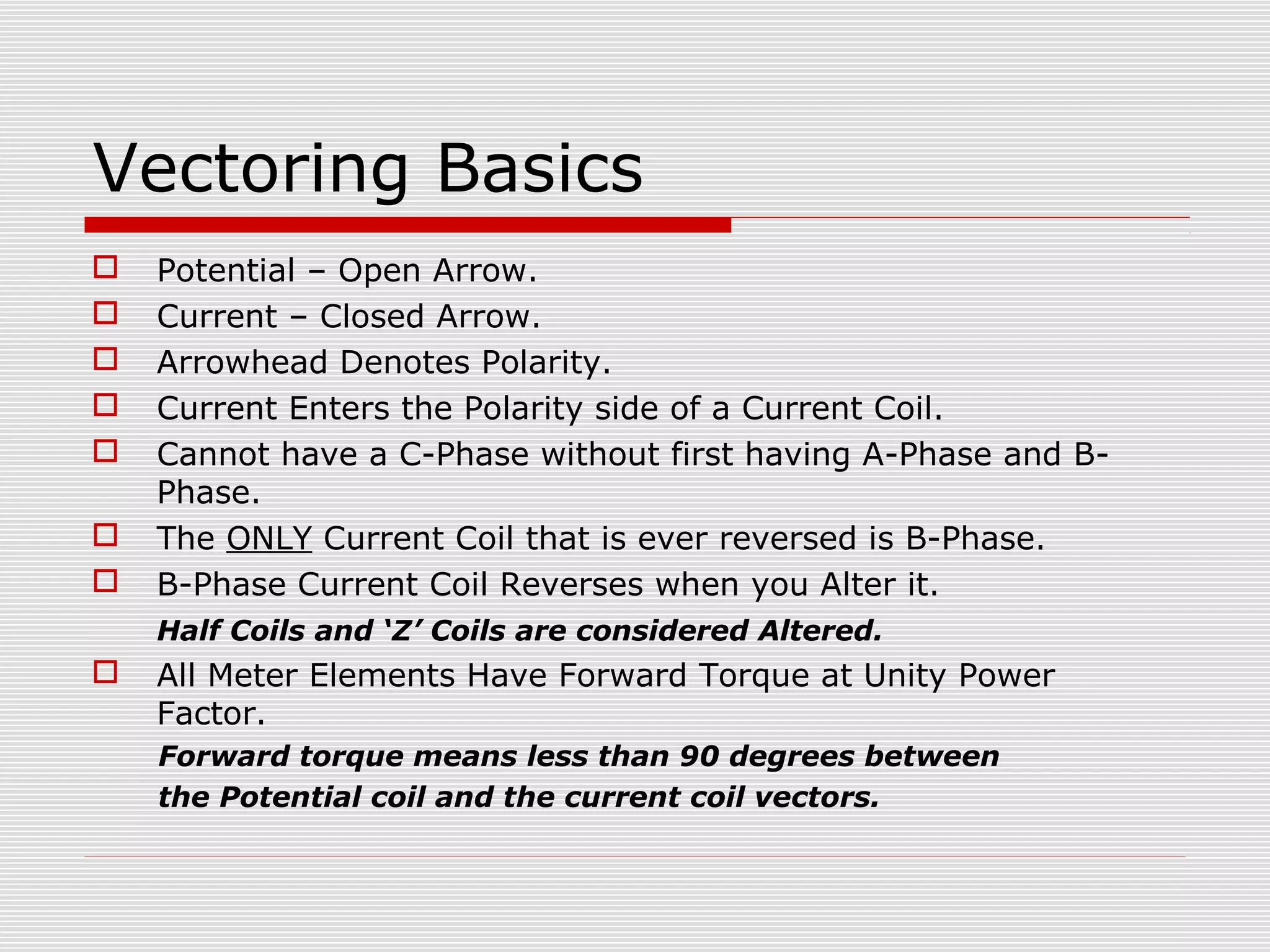
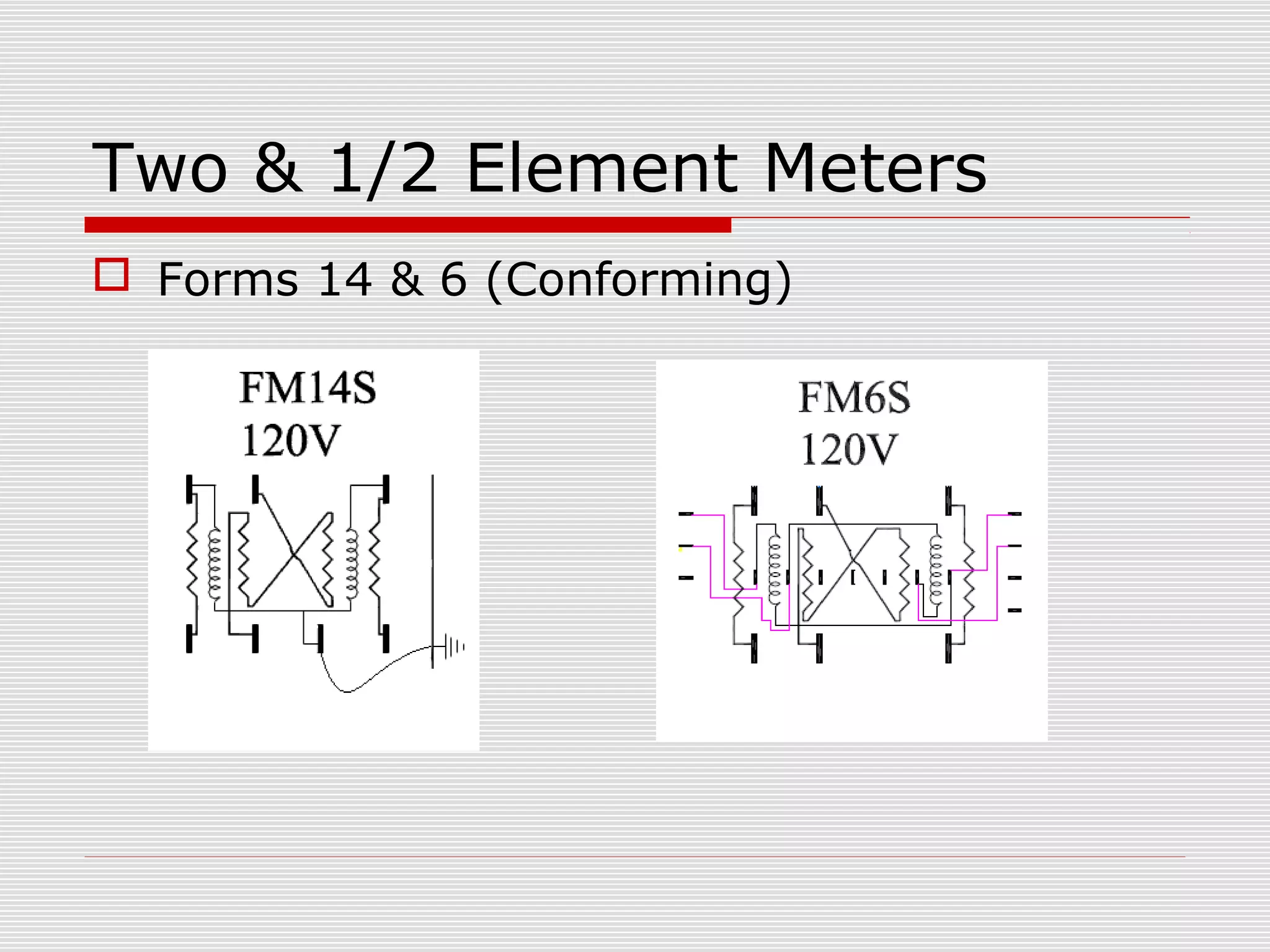
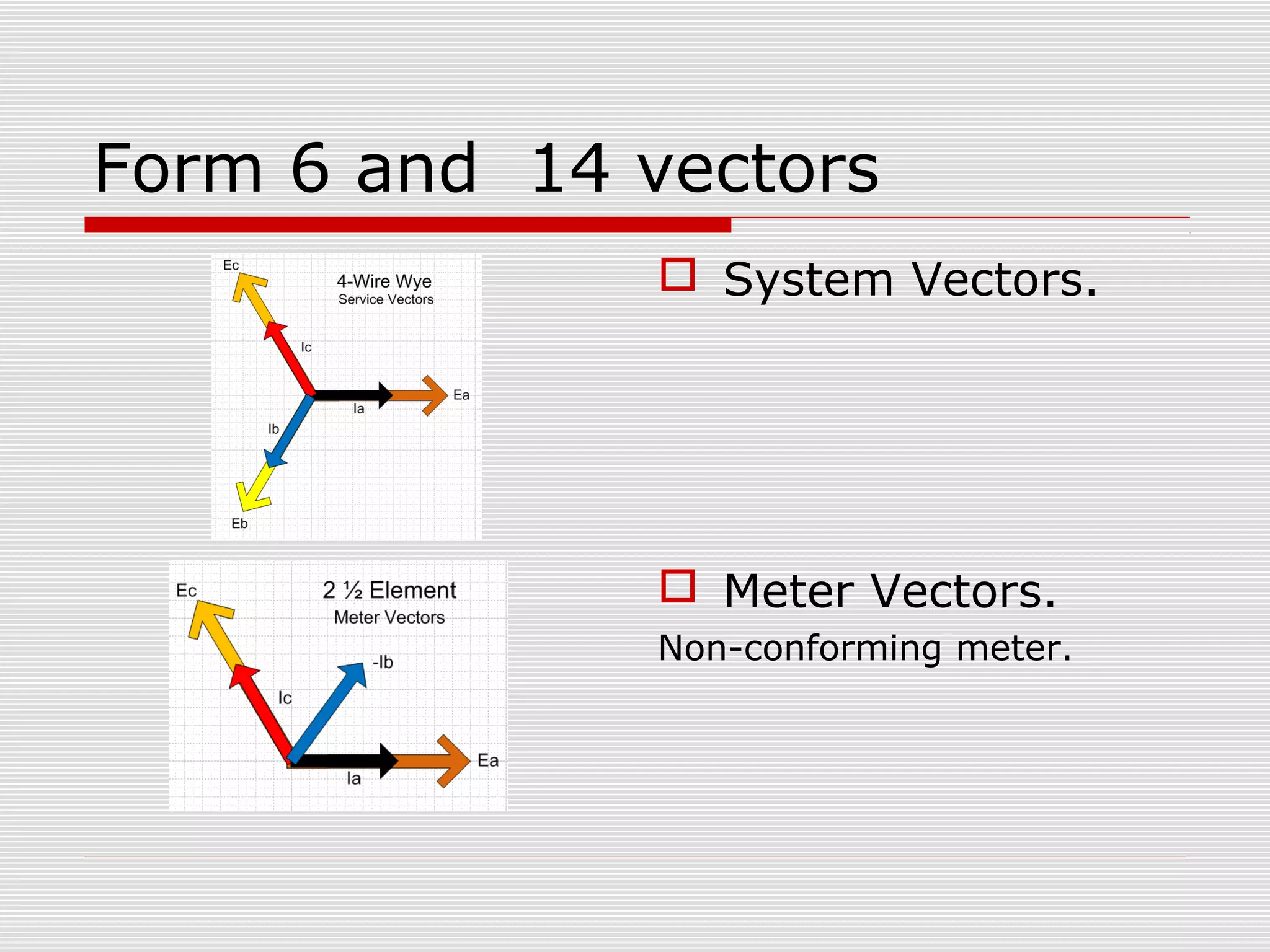

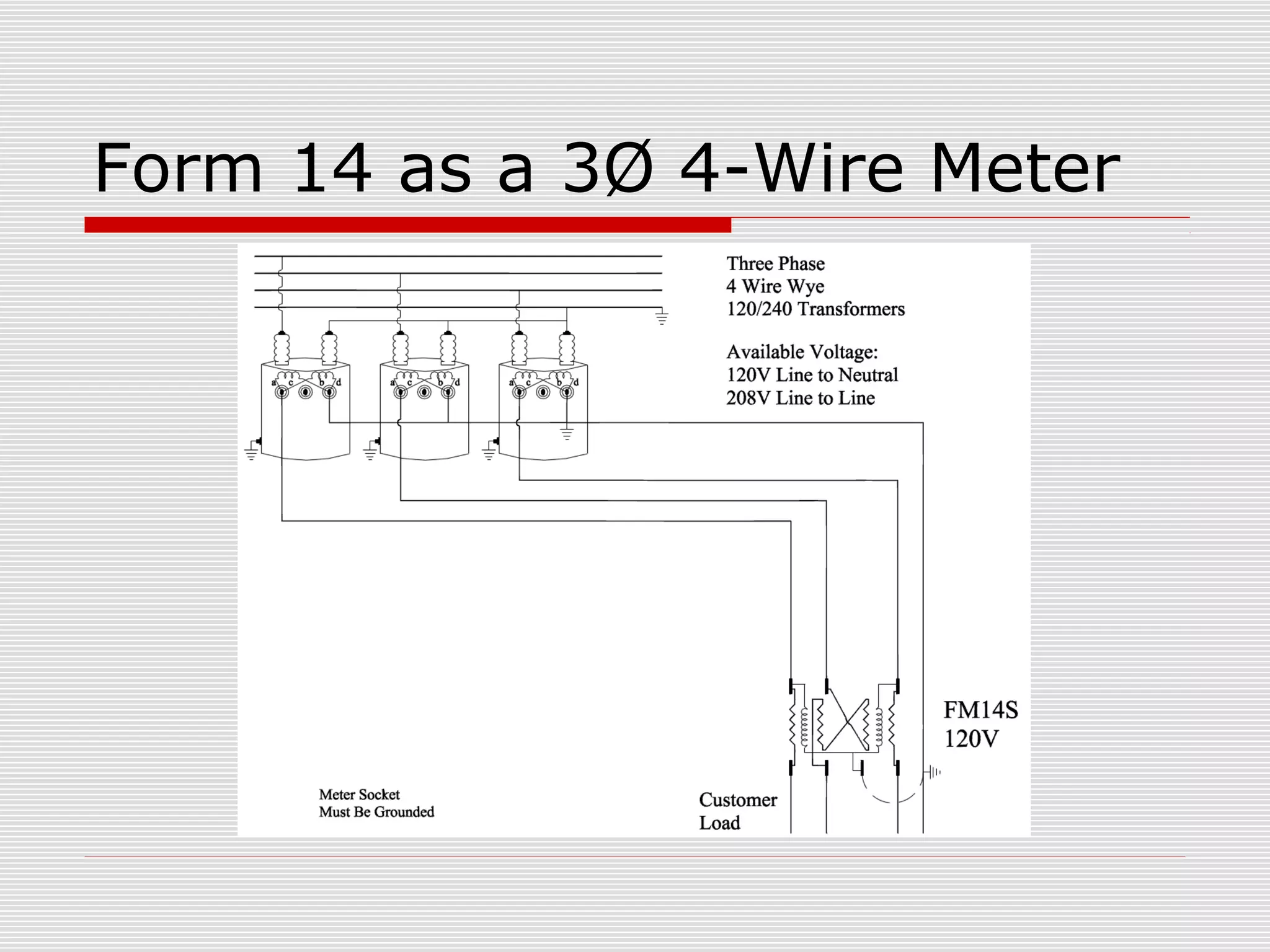
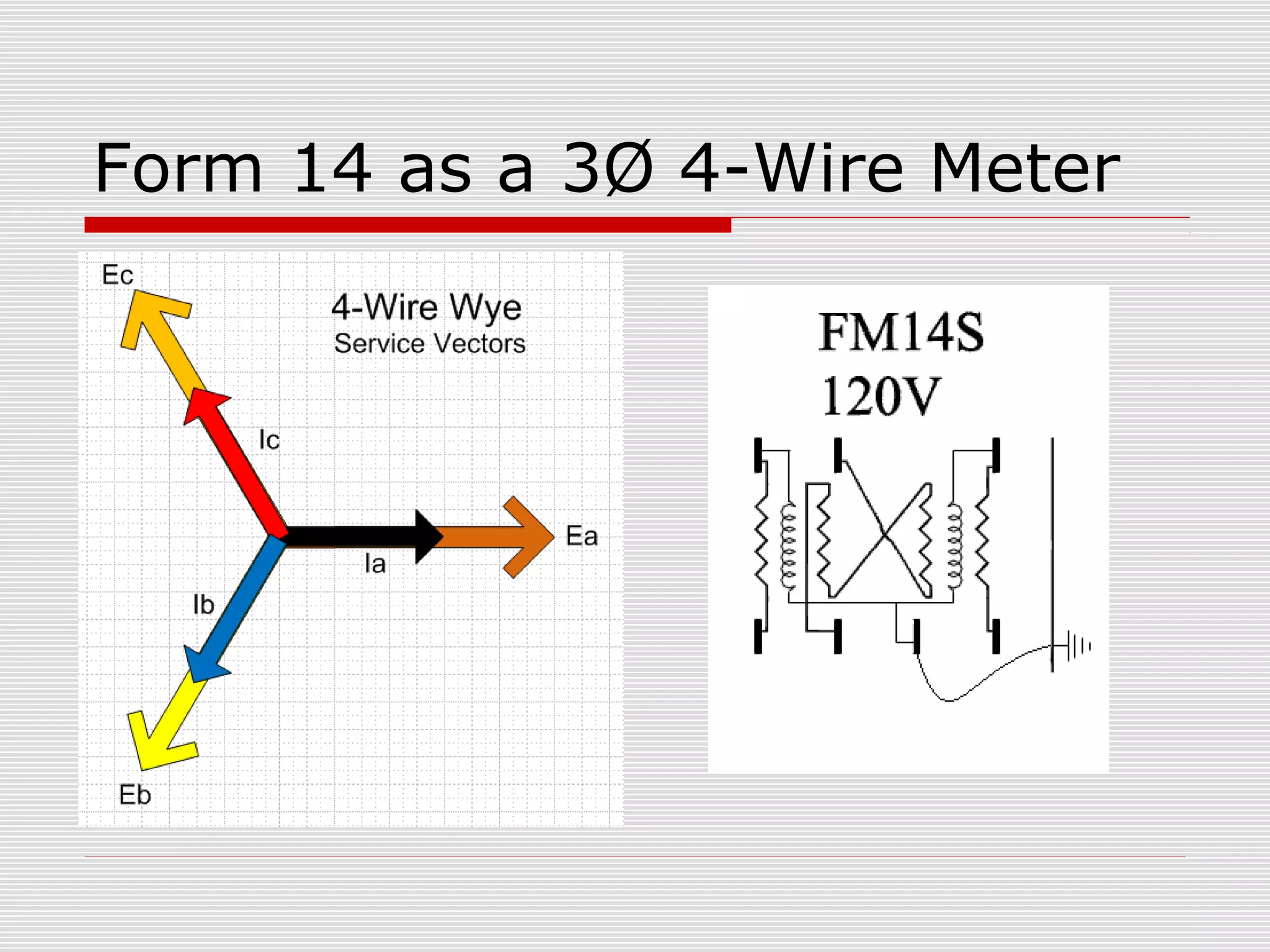
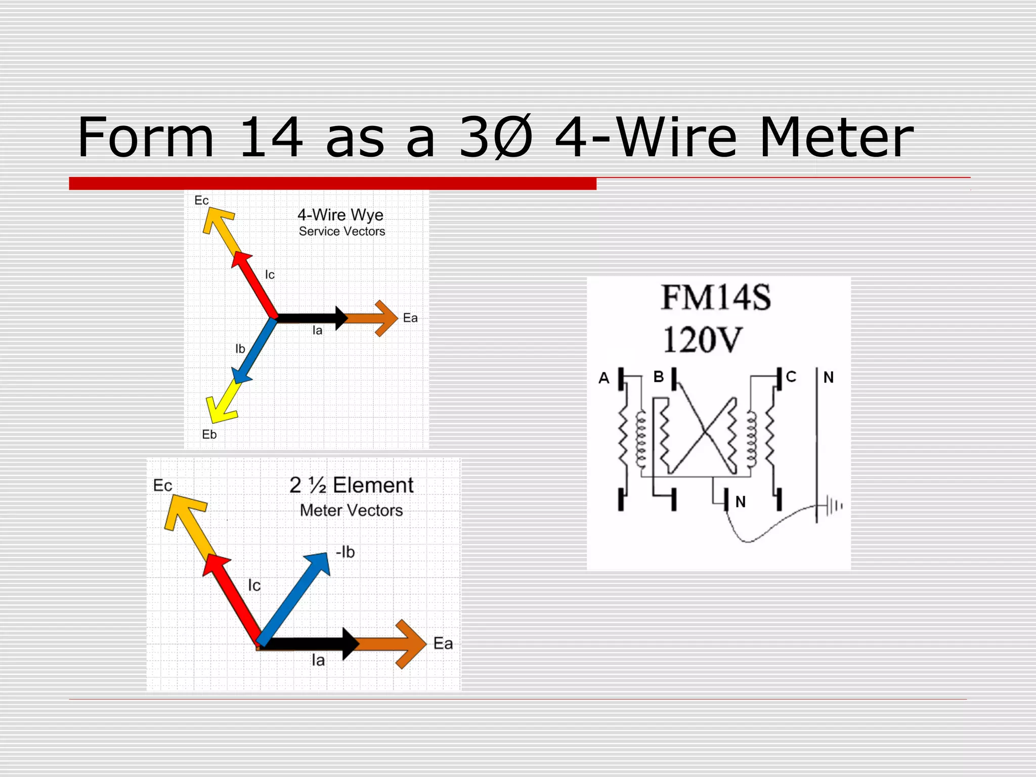
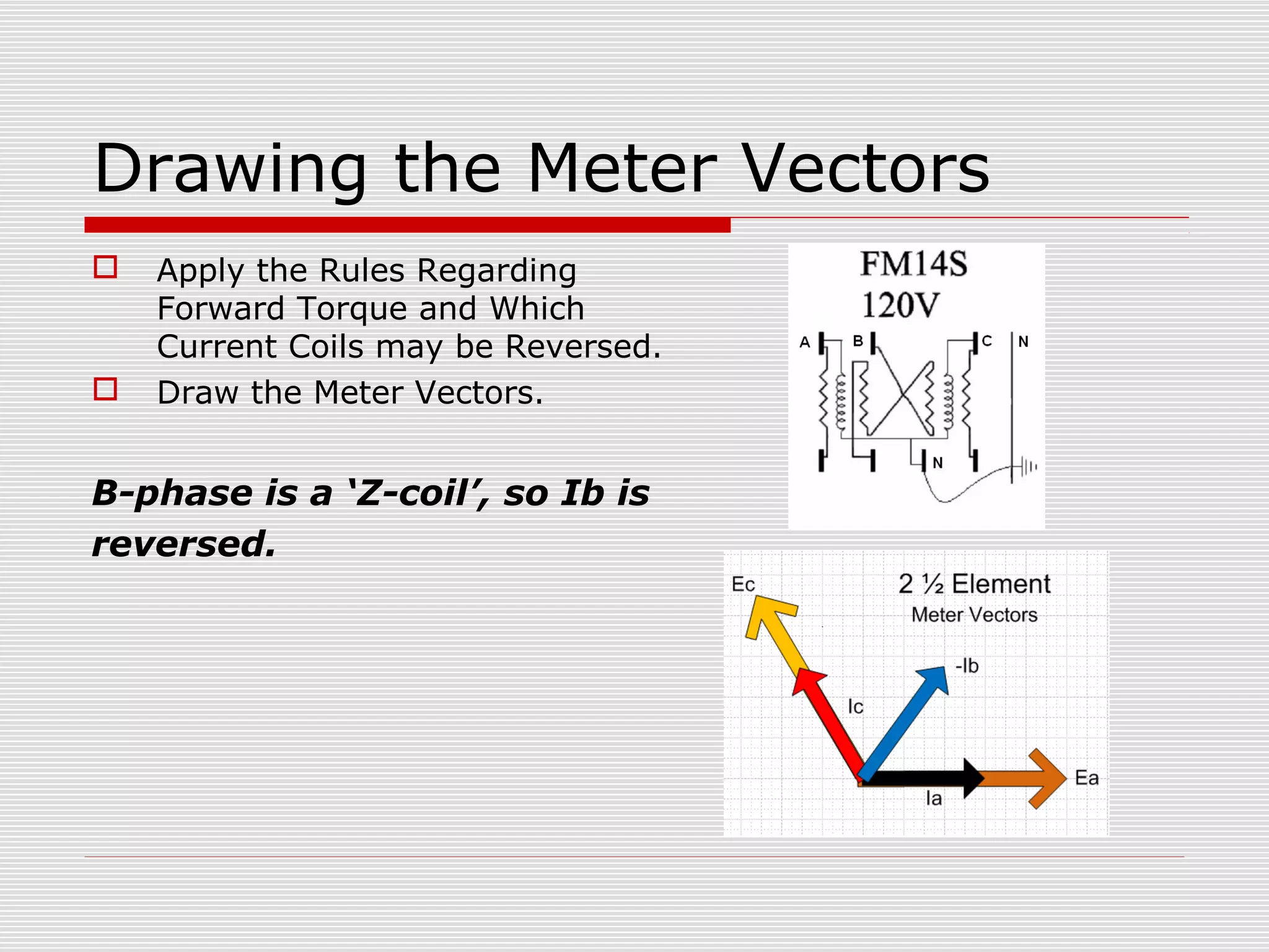
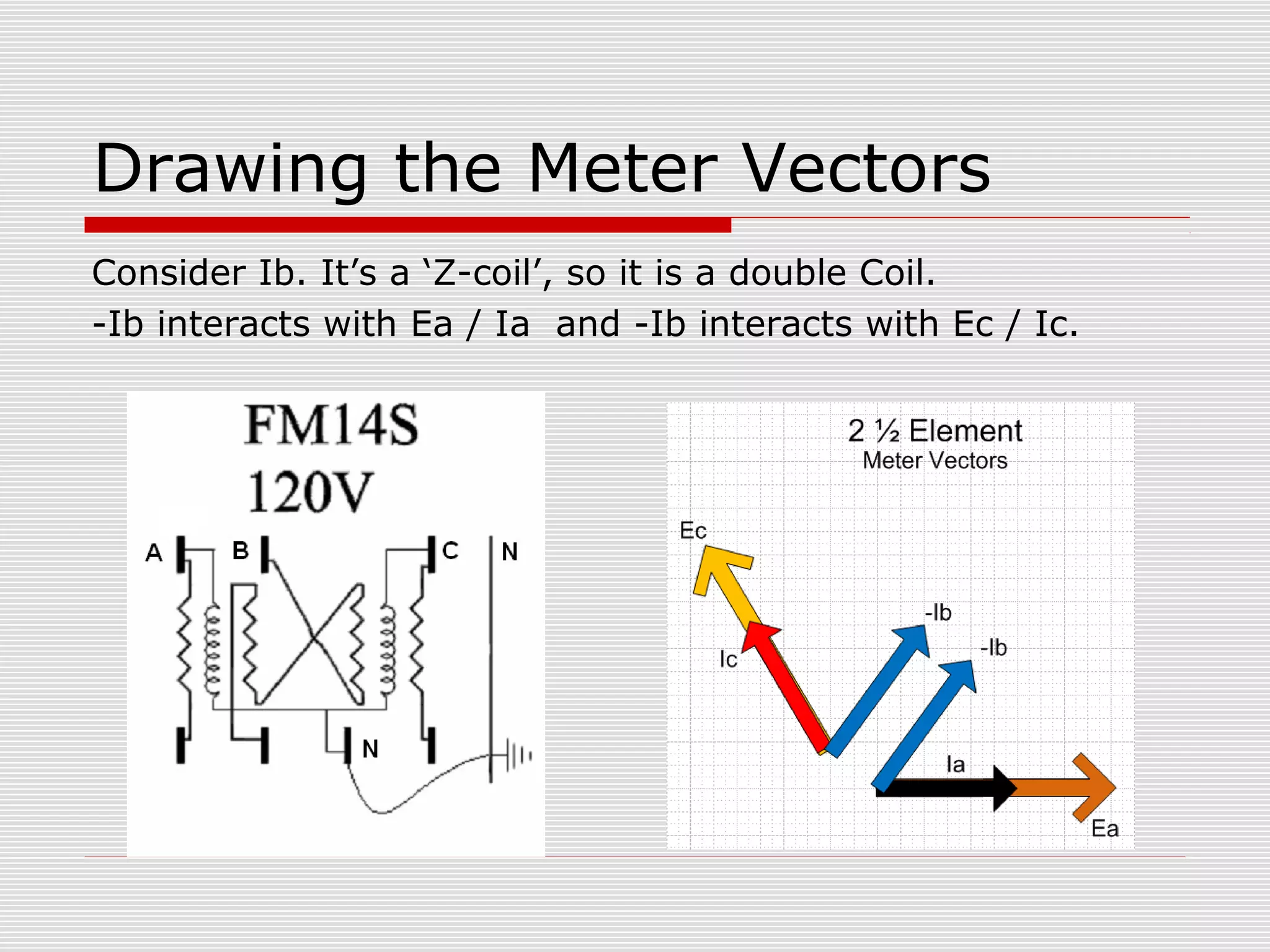
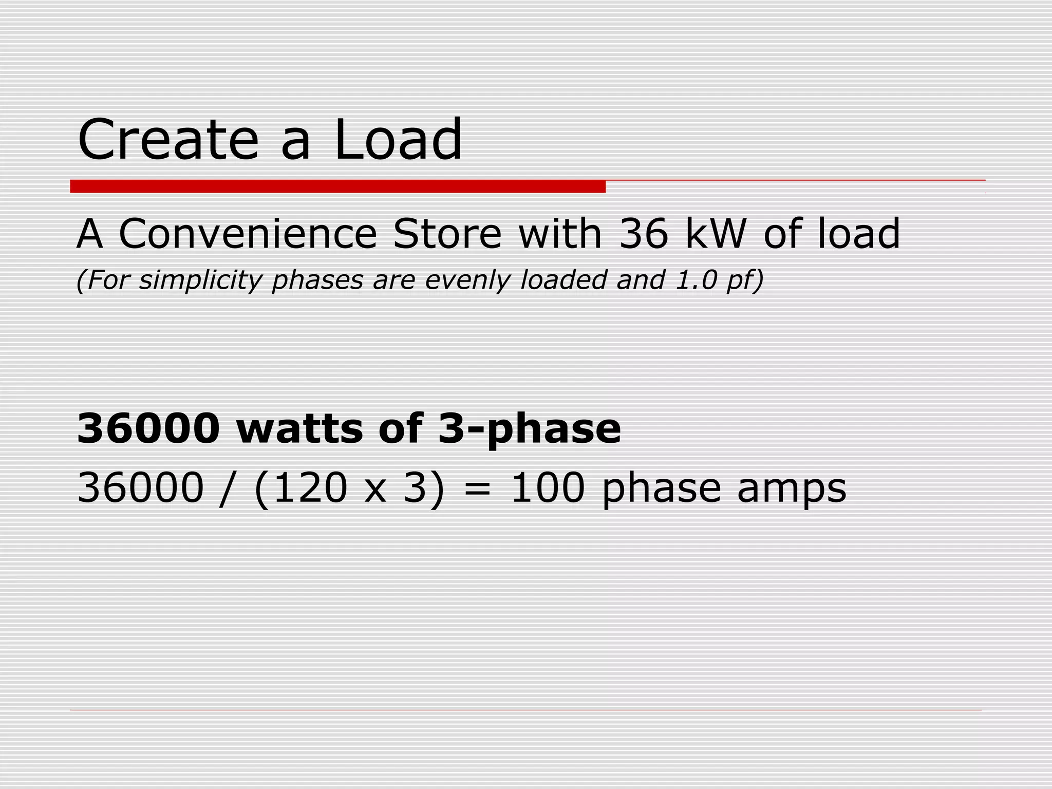
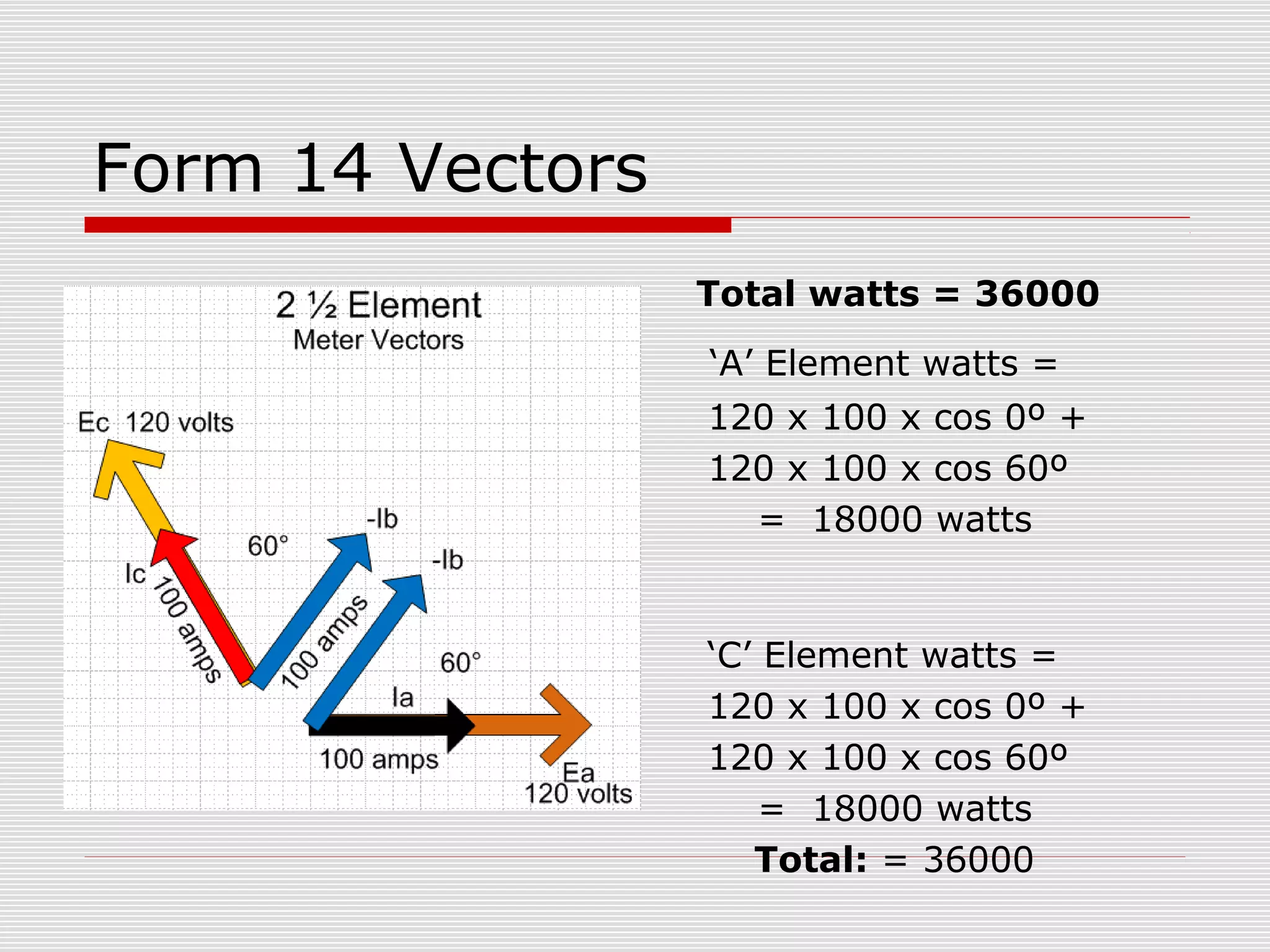
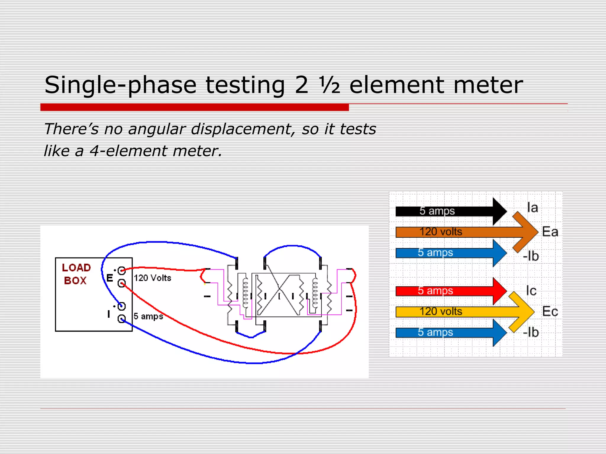
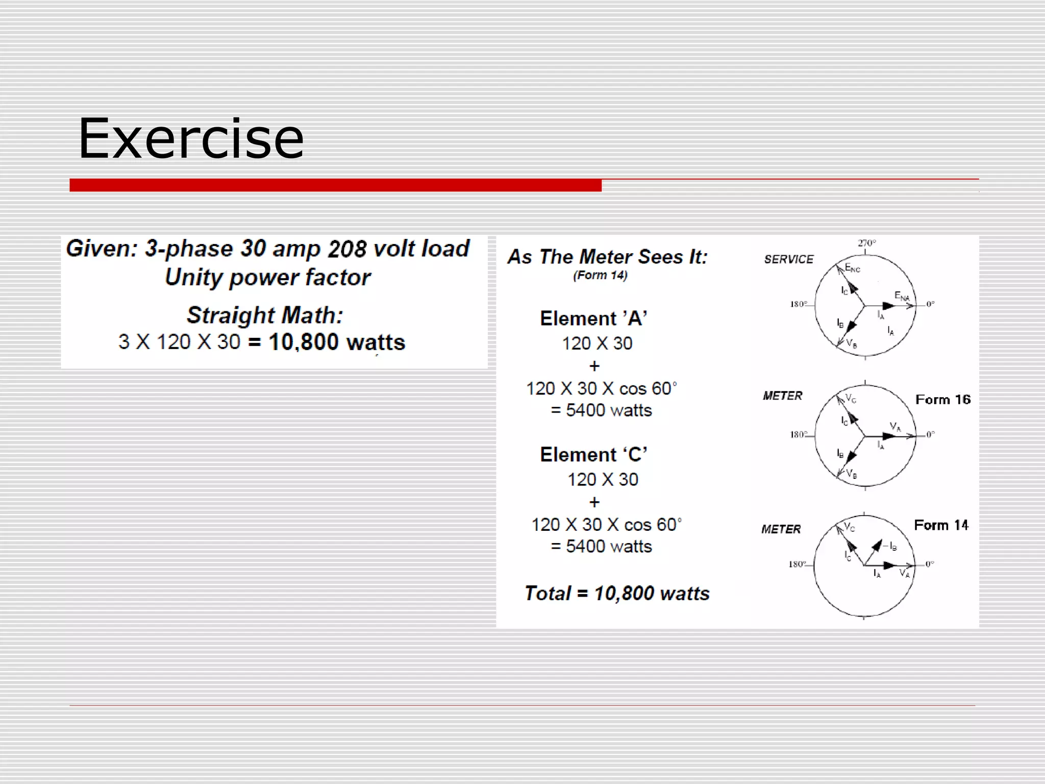
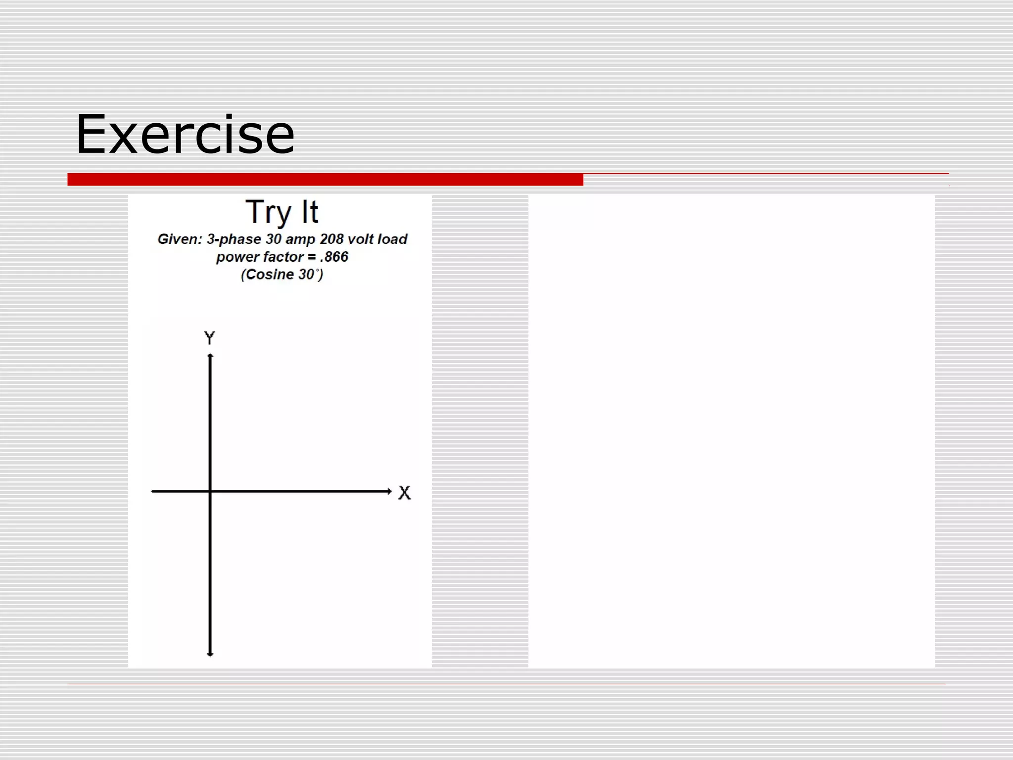


This document provides an overview of vectoring basics for electricity meters. It discusses the key principles of vectoring including starting with a zero reference voltage, the meanings of potential and current arrows, which current coils can be reversed, and that all meter elements have forward torque at unity power factor. It then covers the sequence for vectoring a meter, examples of vector diagrams for different meter types and wiring configurations (including 2 1/2 element meters), and provides an example problem of calculating load for a convenience store.


![Incomplete PPT on first topic.pptx [Autosaved] [Autosaved].ppt](https://cdn.slidesharecdn.com/ss_thumbnails/incompletepptonfirsttopic-230311215449-64eb2ec5-thumbnail.jpg?width=640&height=640&fit=bounds)