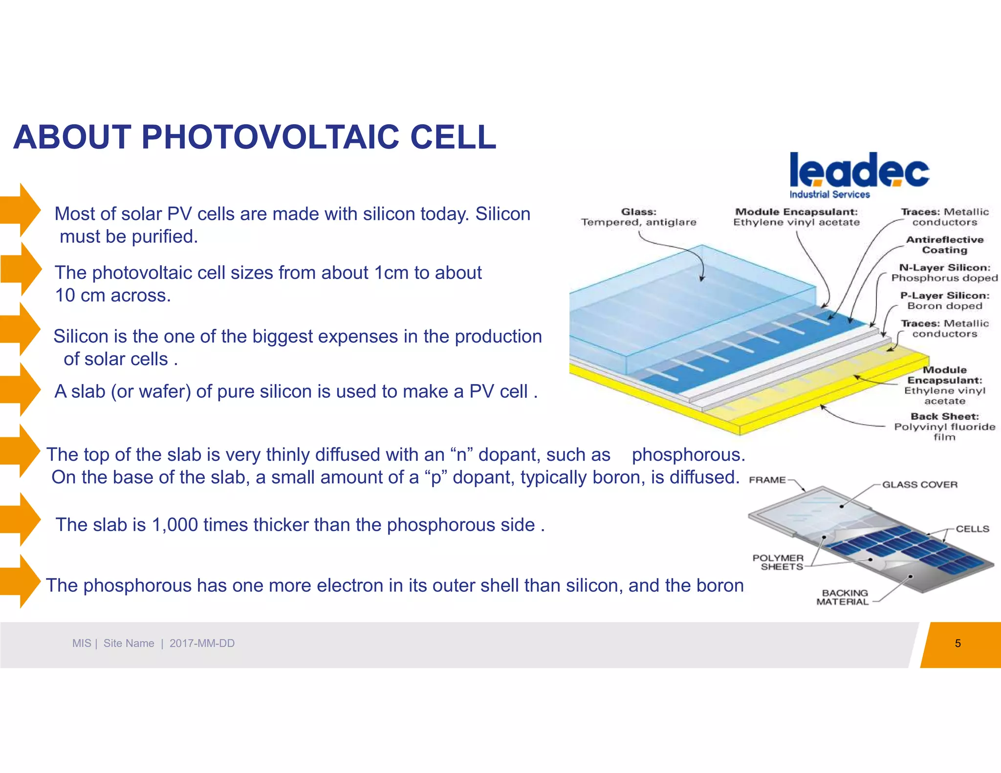
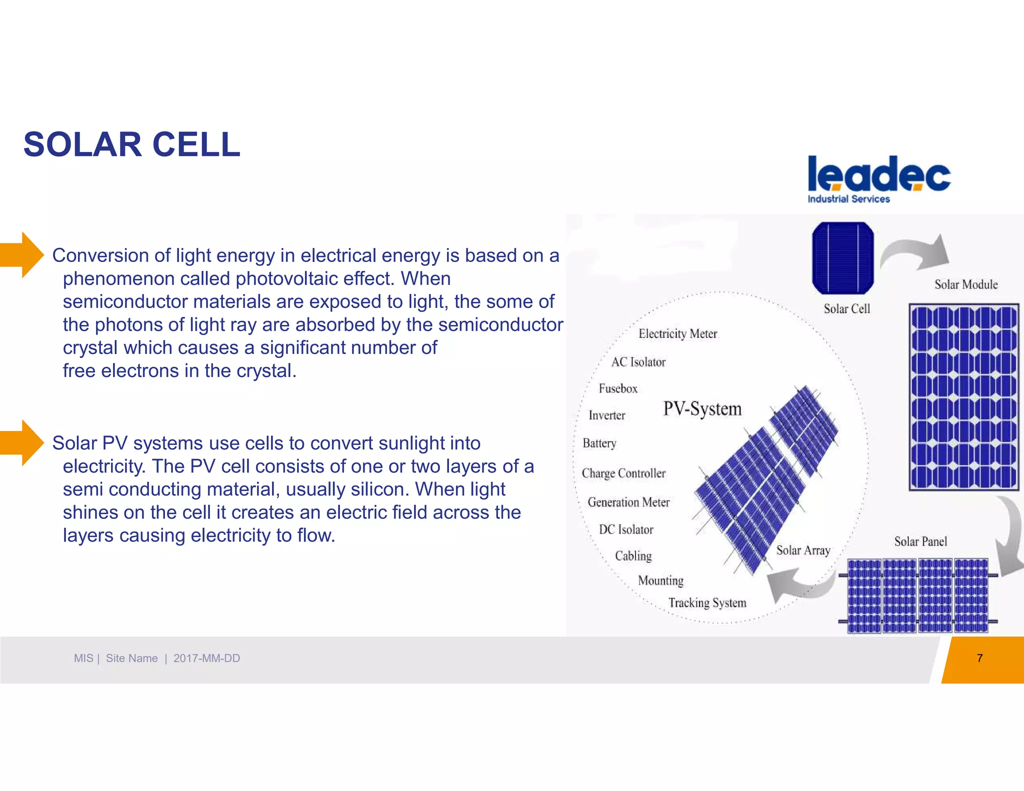
PLANT SOLAR PPT
APL KHANDALA
1MIS | Site Name | 2017-MM-DD
WHAT IS SOLAR POWER PLANT
2MIS | Site Name | 2017-MM-DD
Solar energy is the energy that is available from the sun in abundance. Solar power is the conversion of
sunlight into electricity .
As electricity plays a key role in our day to day life we need it in abundance, as sunlight is clean,
and is available for free solar power is created from it .
Solar powers plants that are being for some time now, helps in supplying energy. They act as a source of
energy which is total pollution free and environment friendly.
These solar power plants are huge and hence require lots of pace. Thus the perfect place for their
setup would be desserts and other barren unoccupied lands.
Apart from the solar power plant that makes use of tracking mirrors we have the photovoltaic cells
that help in converting the sunlight into electricity directly. These cells are made of
semiconductors i.e. crystalline silicon which are cheap and work effectively.
3MIS | Site Name | 2017-MM-DD
ATOMIC STRUCTURE
THREE PARTICLES:- The atom is made of three particles: Protons, which are positively charged;
Neutrons, which have no electrical charge (neutral); and Electrons, which are negatively charged. The
neutron is the largest particle, being ever so slightly more massive than the proton .
NUCLES :- The nucleus is the location of the protons and neutrons. It is the place where
the mass of the atom is concentrated, and has an overall positive charge.
ELECTROSTATIC FORCE :- The electrons are moving at nearly the
speed of light. They are bound to the atom because of the
electrostatic attraction between them and the protons in the nucleus.
Their momentum keeps them from crashing into the center of the
atom.
STRONGE NUCLEAR FORCE :- . The nucleus stays together in
spite of the electrostatic repulsion between the protons. This is
because of a fundamental force, called strong nuclear force, that is
associated with neutrons. It keeps the nucleus together.
4MIS | Site Name | 2017-MM-DD
RADIENT ENERGY
5MIS | Site Name | 2017-MM-DD
ABOUT PHOTOVOLTAIC CELL
A slab (or wafer) of pure silicon is used to make a PV cell .
The phosphorous has one more electron in its outer shell than silicon, and the boron has one less.
Most of solar PV cells are made with silicon today. Silicon
must be purified.
The photovoltaic cell sizes from about 1cm to about
10 cm across.
Silicon is the one of the biggest expenses in the production
of solar cells .
The top of the slab is very thinly diffused with an “n” dopant, such as phosphorous.
On the base of the slab, a small amount of a “p” dopant, typically boron, is diffused.
The slab is 1,000 times thicker than the phosphorous side .
6MIS | Site Name | 2017-MM-DD
WORKING OF PHOTOVOLTAIC CELL
1. Where the n-type silicon and p-type silicon meet, free electrons from the
n-type flow into the p-type for a split second, then form a barrier to
prevent more electrons from moving between the two sides. This point
of contact and barrier is called the p-n junction
2. When both sides of the silicon wafer are doped, there is a negative
charge in the p-type section of the junction and a positive charge in the
n-type section of the junction due to movement of the electrons and
“holes” at the junction of the two types of materials. This imbalance in
electrical charge at the p-n junction produces an electric field between
the p-type and n-type.
3.The PV cell is placed in the sun, photons of light strike the electrons in
the p-n junction and energize them, knocking them free of their atoms.
These electrons are attracted to the positive charge in the n-type silicon
and repelled by the negative charge in the p-type silicon.
7MIS | Site Name | 2017-MM-DD
SOLAR CELL
Solar PV systems use cells to convert sunlight into
electricity. The PV cell consists of one or two layers of a
semi conducting material, usually silicon. When light
shines on the cell it creates an electric field across the
layers causing electricity to flow.
Conversion of light energy in electrical energy is based on a
phenomenon called photovoltaic effect. When
semiconductor materials are exposed to light, the some of
the photons of light ray are absorbed by the semiconductor
crystal which causes a significant number of
free electrons in the crystal.
PV ARREY COMPONENTS
8MIS | Site Name | 2017-MM-DD
• PV Cells
• Modules
• String
• Arrays
CONVERTING SOLAR ENERGY INTO
ELECTRICITY
9MIS | Site Name | 2017-MM-DD
Photovoltaic cell panels consist of semiconductors . Photovoltaic cell semiconductors
positively and negatively charged .
When light shines on the semiconductor, the electric
field across the junction between these two layers
causes an electric current.
The greater the intensity of light the greater the generation of electricity .
The photovoltaic effect involving conversion of solar energy
into electrical energy in semiconductor element. Electrons
goes to the semiconductor N and holes goes to the
semiconductor P.
TYPES OF SOLAR POWER PLANT
10MIS | Site Name | 2017-MM-DD
This is a method that makes use of the energy of the sun for providing electricity for the working of
different appliances.
Photovoltaic Solar Energy Plant:- This as mentioned before makes use of photovoltaic cells or solar cells as it is
called for generating power. It is used for house wiring and powering electrical
appliances.
Thermal Energy Solar Power Plant:- This can be used for heating water and drying clothes. Also this system
is used for heating houses during cold days.
Concentrating Solar Power Plant:- This type of solar power plant is very similar to the photovoltaic one.
However, the only difference is it makes use of mirrors and lenses for
trapping sunlight. The trapped sunlight will then be directed to the
photovoltaic cells that will convert into heat energy. These plans are used
by big companies and industries.
SOLAR PHOTOVOLATIC MODULE COMPARISON
11MIS | Site Name | 2017-MM-DD
Cell Type Efficiency of Cell Construction Area Required/
MW
Remarks
Mono
Crystalline
Around 18 - 24% Silicon wafer used to make them is
cut from a SINGLE CRYSTAL silicon.
3-4 Acres Benefit- Highest Efficiency, less area required
compared with others
Drawback-High Cost, Problem at higher
temperature compared with other technology
Poly/Multi
Crystalline
Around 14-18% Molten silicon is cast into ingots of
polycrystalline silicon, then saw-cut
in to very thin wafers and assembled
into complete cells.
4-5 Acres Benefit- Cheaper than Mono, better temperature
de-rating co-efficient compared with Mono
Drawback- Slightly less efficient compared with
mono, more space required compared with Mono
Thin Films
(different
types)
1. Amorphous Silicon 6-10%
2. Cadmium Telluride 10-
11%
3. Copper Indium Gallium
Dieseline 12-14%
Thin film, amorphous silicon cells
are made up of silicon atoms in thin
layer rather than a crystal structure. It
can absorb light more readily than
crystalline silicon, so cells can be
thinner.
7.5-9 Acres Benefits- Best shade tolerance, Best under
hotter temperature compared with all other
technology.
Drawback-Lowest efficiency, higher space
requirement, product is not environment friendly.
12MIS | Site Name | 2017-MM-DD
SOLAR PHOTOVOLATIC MODULE
COMPARISON
MONO CRYSTALLINE POLY CRYSTALLINE THIN FILM
Poly Crystalline solar modules as Poly modules are widely used for optimum
performance in Indian conditions , economical and need lesser area.
SOLAR PANEL
13MIS | Site Name | 2017-MM-DD
PV cells are made of special materials called semiconductors and in this case, silicon.
When a photon (a light particle) hits the panel, it has enough energy to knock an electron loose, allowing it
to flow freely.
The panel then has several electrical fields to force the electrons to move in a certain direction, creating a
current which can be used to do work.
To complete the PV module, several layers are added.
A - Cover Glass
B - Antireflective Coating
C - Contact Grid
D - N-type Silicon
E - P-type Silicon
F - Back Contact
BENEFITS OF SOLAR POWER PLANT
14MIS | Site Name | 2017-MM-DD
As solar power is a renewable source of energy it available free of cost everywhere .
It is a great way to save money as most of the electricity is consumed from the power plants it can help
you to reduce bills .
It help in keeping the environment pollution free and generating electricity easily .
When there is no power you can use the electricity generated from solar power plant .
A solar power plant requires very low maintenance and at the same time have long life span
Using photovoltaic system helps in increasing the value of your home .
Solar power plants help in supplying huge amount of electricity.
It can be used for lighting, mobile charging, security cameras, park lighting , domestic appliances and
industrial purposes.
DEFINATIONS
15MIS | Site Name | 2017-MM-DD
SPV = Solar Photovoltaic .
AJB = Array Junction Box has fuse and surge protection inside , Isolation switch between
inverter and solar array .
PR = Performance Ratio is ratio of actual energy output vs. theoretical energy output for the
particular period . It is Represented in % .
SOLAR ARRAY = A Number of module string ( solar panel string ) connected in parallel to produce
the Required current .
MODULE STRING = A number of module string (solar panels ) connected in series to produce the
required operating voltage .
ACDB = AC Distribution Board is used to connect the output of inverter .
SOLAR INVERTER
16MIS | Site Name | 2017-MM-DD
Two types of inverters are available for the solar DC power conversion in to AC power.
Central Inverters are widely used in Utility scale Ground mounted or MW scale roof top installation in
following condition.
1. All solar modules facing is similar. (Ground mount or large roofs)
2. Inverter installation is near to the Solar panels. (as central inverter are ground mounted)
3. MW scale solar plants.
4. Central inverters are cheaper compared with string inverter.
String Inverters are widely used in Roof top Solar installation.
1. Different Facing of the solar Panels. (Distributed Roofs)
2. When wall mounting installation is required to avoid extra cable cost.
3. When smooth controlling of the solar power is required.
4. String inverter is more reliable as in case of maintenance or
failure of the Inverter only small section of the system will affect.
String
Central
CENTRAL VS STRING INVERTER
17MIS | Site Name | 2017-MM-DD
PHOTOVOLATIC SOLAR PLANT SLD
18MIS | Site Name | 2017-MM-DD
K.S P.P
ABOUT KHANDALA SOLAR PLANT
19MIS | Site Name | 2017-MM-DD
Total number of installed module in Plant = 12753 .
Total plant capacity = 4 MW .
Total number of inverter Installed in plant = 59 .
Ratting of all inverters = 60KVA .
Voltage rating of one plate is 45V ideally.
Three types of solar plates according to their power rating:
1. 310W, 2. 315W, 3. 320W.
Input voltage of inverter is between: 565 Vdc-1000 Vdc.
As per voltage requirement connect solar plates in series and parallel.
Total number of ACDB Installed in plant = 16 .
SOLAR ACDB
20MIS | Site Name | 2017-MM-DD
Alternating Current Distribution board is used to receives the AC power
from the solar inverter and directs it to AC loads through the
distribution board.
Alternating Current Distribution board is always used to connect
the solar inverter output side .
It is used to monitor all electrical parameters like incoming
Voltage , current , frequency , power factor etc.
All the 415 AC or 230 volt devices and other equipment's like bus
support insulator ,Circuit Breaker ,VTs are mounted inside the
switchgear for continuous operation as per following conditions.
1. Supply voltage variation +/ - 10% .
2. Frequency Variation + /- 3% .
SOLAR ARRAY JUNCTION BOX ( AJB )
21MIS | Site Name | 2017-MM-DD
The PV array junction box enables the bundling of the necessary
number of PV strings for the inverter. Each inverter requires a
PV array junction box.
Solar Array junction box used for Photovoltaic protection
equipment's .
Solar Array Junction Box has fuses & surge protection inside &
works as an isolator between Inverter and Solar Array.
One isolator switch is used for disconnection the Photovoltaic
string and inverter .
SMA INVERTER ( MLX-60 )
22MIS | Site Name | 2017-MM-DD
LIVE PARTS:-
A = AC Terminals .
E = PV Terminals .
Protected Extra Low Voltage
B = Device Grounding .
G= Ethernet Interface x 2 .
H= RS485 Interface .
Miscellaneous
C = Ac overvoltage Protection SPDs .
D = Dc overvoltage Protection SPDs .
F = PV load Break switch .
23MIS | Site Name | 2017-MM-DD
SMA INVERTER ( MLX 60 )
The SMA Inverter MLX-60 model is only used for Grid-connected
Photovoltaic System .
The inverter converts direct current from Photovoltaic modules into
Grid-complaint three phase alternating current .
This inverter must be connected to a utility grid and with a sufficient
number of PV modules .it is not suitable for other applications .
This inverter plays very important role for Grid connected PV solar
generation System .
SMA inverter manager must be connected for operation and
communication between the inverters up to 42 inverter
can connect with single SMA communication manager .
PLANT SOLAR SLD
24MIS | Site Name | 2017-MM-DD
AJB AJB
INVERTER
FIELD
ACDB ACDB AT PCC
PCC BREAKER
PV STRING
PV STRING
HOW TO CALCULATE SOLAR PR%
25MIS | Site Name | 2017-MM-DD
Performance Ratio (PR) = Actual Energy Genration KWH .
Calculated Nominal Generation KWH
X Grid Uptime
Actual generation kwh = Actual energy output at LT panel .
Calculated Nominal Generation KWH = Cumulative solar radiation in kWh/m2 × solar plant capacity in KWp (DC side)
= ( 1.94 X Radiation Level X Total number of modules X Module Efficiency .)
For example
Actual energy generation, kWh = 8031
Cumulative solar radiation is =4.1 kWh/m2
Grid up time = 100%
Formula = Total unit KWH / Calculated nominal generation KWH .
= 8031 / ( 1.94 x 4.1 x 6460 x 0.1594 ) + ( 1.94 x 4.1 x 6293 x 0.16 )
= 8031 / ( 8190 + 8008 )
= 8031 / 16198
In above case, PR =
%
= 49.98% Plant module
HOW TO CALCULATE SOLAR MODULE
EFFICENCY
26MIS | Site Name | 2017-MM-DD
1. Solar module efficiency is as below.
Solar module efficiency (%) = x 100
Where,
Ideal area= 1 m2, as standard radiation received on earth is 1000 watt/m2
Actual area= Solar module carpet area required for 1000 watt installation
For example, if the module capacity is 300 watt and size is 2m2(2 mtr x 1 mtr) than
area required for 1000 watt = = 6.66 m2.
In above case solar module efficiency,
=
.
x 100 = 15.01%
SOLAR MODULE LIFE AND LOSSES
27MIS | Site Name | 2017-MM-DD
Performance ratio of the plant is always below 100% because
of the following typical losses.
1. Temperature loss (10%)- As module efficiency decrease with increase in
the temperature
2. Module quality and array mismatch loss (4%)- As all the modules are not
100% identical and solar radiation on each modules vary because of the
installation mismatch.
3. Soiling loss (2%)- Min dust related loss.
4. Ohmic loss (2.6%)- DC resistance loss .
5. Inverter loss (1.9%)-DC to AC conversion loss .
Solar modules have degradation as per curve
shown, 20% degradation at the end of 25th
year.
First year degradation 3% and 0.7%
degradation every subsequent year.
SPB ( PACKING + RCC ) AREA SOLAR PLANT
28MIS | Site Name | 2017-MM-DD
Total installed capacity at SPB = 352.29 KW
Total inverter = 5 Nos ( 60 kva ) .
AC Capacity of
Inverter (KW)
Solar (DC) Capacity
on Inverter (KVA) AJB Strings
Modules/
string
Module
rating
60KW 60KVA AJB1 12 20 310W
60KW 60KVA AJB2 12 20 310W
60KW 60KVA AJB3 11 20 315W
60KW 60KVA AJB4 11 20 315W
60KW 60KVA AJB5 12 20 315W
Total ACDB = 2 Nos .
Inverter Manager at SPB PCC Room
Total Installed Module = 1126 Nos .
FG SOUTH AREA SOLAR PLANT
29MIS | Site Name | 2017-MM-DD
Total installed capacity at FG South = 446.4 KW
Total inverter = 6 Nos ( 60 kva ) .
Total ACDB = 1 Nos .
Inverter Manager at SPB PCC Room
AC Capacity of
Inverter (KW)
Solar (DC)
Capacity on
Inverter
(KVA)
AJB Strings
Modules
/string
Module
rating
60KW 60KVA AJB1 12 20 310W
60KW 60KVA AJB2 12 20 310W
60KW 60KVA AJB3 12 20 310W
60KW 60KVA AJB4 12 20 310W
60KW 60KVA AJB5 12 20 310W
60KW 60KVA AJB6 12 20 310W
Total Installed Module = 1440 Nos.
FG NORTH AREA SOLAR PLANT
30MIS | Site Name | 2017-MM-DD
Total installed capacity at FG North = 440.2 KW
Total inverter = 6 Nos ( 60 kva ) .
Total ACDB = 1 Nos .
Inverter Manager at WPB PCC Room
AC Capacity of
Inverter (KW)
Solar (DC)
Capacity on
Inverter
(KVA)
AJB Strings
Modules
/string
Module
rating
60KW 60KVA AJB7 12 20 310W
60KW 60KVA AJB8 12 20 310W
60KW 60KVA AJB9 12 20 310W
60KW 60KVA AJB10 12 20 310W
60KW 60KVA AJB11 11 20 310W
60KW 60KVA AJB12 12 20 310W
Total Installed Module = 1420 Nos.
WPB ( PACKING + RCC ) AREA SOLAR PLANT
31MIS | Site Name | 2017-MM-DD
Total installed capacity at WPB = 557.1 KW
Total inverter = 8 Nos ( 60 kva ) .
Total ACDB = 1 Nos .
Inverter Manager at WPB PCC Room
AC Capacity of
Inverter (KW)
Solar (DC)
Capacity on
Inverter (KVA)
AJB Strings
Modules
/string
Module
rating
60KW 60KVA AJB1 12 20 310W
60KW 60KVA AJB2 12 20 310W
60KW 60KVA AJB3 12 20 310W
60KW 60KVA AJB4 12 20 310W
60KW 60KVA AJB5 10 20 310W
60KW 60KVA AJB6 11 20 315W
60KW 60KVA AJB7 11 20 315W
60KW 60KVA AJB8 11 20 315W
Total Installed Module = 1787 Nos.
RMG-1 AREA SOLAR PLANT
32MIS | Site Name | 2017-MM-DD
Total installed capacity at SPB = 334.8 KW
Total inverter = 5 Nos ( 60 kva ) .
AC Capacity of
Inverter (KW)
Solar (DC) Capacity
on Inverter (KVA) AJB Strings
Modules/
string
Module
rating
60KW 60KVA AJB1 10 20 310W
60KW 60KVA AJB2 10 20 310W
60KW 60KVA AJB3 11 20 310W
60KW 60KVA AJB4 11 20 310W
60KW 60KVA AJB5 12 20 310W
Total ACDB = 1 Nos .
Inverter Manager at U-3 PCC Room
Total Installed Module = 1080 Nos.
BG-1 AREA SOLAR PLANT
33MIS | Site Name | 2017-MM-DD
Total installed capacity at SPB = 136.4 KW
Total inverter = 2 Nos ( 60 kva ) .
AC Capacity
of Inverter
(KW)
Solar (DC)
Capacity on
Inverter (KVA) AJB Strings
Modules/
string
Module
rating
60KW 60KVA AJB1 10 20 310W
60KW 60KVA AJB2 12 20 310W
Total ACDB = 2 Nos .
Inverter Manager at WPB PCC Room
Total Installed Module = 440 Nos.
ENGG STORE AREA SOLAR PLANT
34MIS | Site Name | 2017-MM-DD
Total installed capacity at SPB = 136.4 KW
Total inverter = 2 Nos ( 60 kva ) .
AC Capacity
of Inverter
(KW)
Solar (DC)
Capacity on
Inverter (KVA) AJB Strings
Modules/st
ring
Module
rating
60KW 60KVA AJB1 12 20 310W
60KW 60KVA AJB2 12 20 310W
Total ACDB = 1 Nos .
Inverter Manager at U-3 PCC Room
Total Installed Module = 440 Nos.
PMG LOW BAY AREA SOLAR PLANT
35MIS | Site Name | 2017-MM-DD
Total installed capacity at FG South = 457.8 KW
Total inverter = 7 Nos ( 60 kva ) .
Total ACDB = 2 Nos .
Inverter Manager at SPB PCC Room
AC Capacity of
Inverter (KW)
Solar (DC)
Capacity on
Inverter
(KVA)
AJB Strings
Modules
/string
Module
rating
60KW 60KVA AJB1 10 20 320W
60KW 60KVA AJB2 10 20 320W
60KW 60KVA AJB3 10 20 320W
60KW 60KVA AJB4 10 20 320W
60KW 60KVA AJB5 11 20 320W
60KW 60KVA AJB6 11 20 320W
60KW 60KVA AJB7 11 20 320W
Total Installed Module = 1430 Nos.
PMG HIGH BAY AREA SOLAR PLANT
36MIS | Site Name | 2017-MM-DD
Total installed capacity at FG South = 435.2 KW
Total inverter = 6 Nos ( 60 kva ) .
Total ACDB = 2 Nos .
Inverter Manager at SPB PCC Room
AC Capacity of
Inverter (KW)
Solar (DC)
Capacity on
Inverter
(KVA)
AJB Strings
Modules/
string
Module
rating
60KW 60KVA AJB1 10 20 320W
60KW 60KVA AJB2 10 20 320W
60KW 60KVA AJB3 10 20 320W
60KW 60KVA AJB4 10 20 320W
60KW 60KVA AJB5 11 20 320W
60KW 60KVA AJB6 11 20 320W
Total Installed Module = 1360 Nos.
FG HIGH BAY SOLAR PLANT
37MIS | Site Name | 2017-MM-DD
Total installed capacity at FG North = 332.8 KW
Total inverter = 6 Nos ( 60 kva ) .
Total ACDB = 1 Nos .
Inverter Manager at WPB PCC Room
AC Capacity of
Inverter (KW)
Solar (DC)
Capacity on
Inverter
(KVA)
AJB Strings
Modules
/string
Module
rating
60KW 60KVA AJB1 10 20 320W
60KW 60KVA AJB2 10 20 320W
60KW 60KVA AJB3 10 20 320W
60KW 60KVA AJB4 10 20 320W
60KW 60KVA AJB5 10 20 320W
60KW 60KVA AJB6 10 20 320W
Total Installed Module = 1040 Nos.
BG-2 AREA SOLAR PLANT
38MIS | Site Name | 2017-MM-DD
Total installed capacity at SPB = 192 KW
Total inverter = 3 Nos ( 60 kva ) .
AC Capacity
of Inverter
(KW)
Solar (DC)
Capacity on
Inverter (KVA) AJB Strings
Modules/
string
Module
rating
60KW 60KVA AJB1 10 20 320W
60KW 60KVA AJB2 10 20 320W
60KW 60KVA AJB3 10 20 320W
Total ACDB = 1 Nos .
Inverter Manager at SPB PCC Room
Total Installed Module = 600 Nos.
FWRW AREA SOLAR PLANT
39MIS | Site Name | 2017-MM-DD
Total installed capacity at SPB = 188.8 KW
Total inverter = 3 Nos ( 60 kva ) .
AC Capacity
of Inverter
(KW)
Solar (DC)
Capacity on
Inverter (KVA) AJB Strings
Modules/
string
Module
rating
60KW 60KVA AJB1 10 20 320W
60KW 60KVA AJB2 10 20 320W
60KW 60KVA AJB3 10 20 320W
Total ACDB = 2 Nos .
Inverter Manager at WPB PCC Room
Total Installed Module = 590 Nos.
AGC MASTER CONTROLLER
40MIS | Site Name | 2017-MM-DD
1 2 3 4
5
6
7
8
16
10 11 12 13 14 15 9
17
18
19
20
21
1. Setup Menu.
2. LED for Pf control . (Green fixed for Import/export)
3. LED Voltage support Active.
4. For Event and Alarm List.
5. LED for Auxiliary supply .
6. LED Indication for Unit is ok .
7. LED for Plant communication ok.
8. LED indication of Auto mode ok .
9. LED Indication for Semi Mode .
10. LED Main Bus Voltage Present .
11. LED Indicate Main Breaker Closed
12. Manual activation of breaker .
13. LED Indicate Main is Present .
14. Select Semi Mode/ Local Operation.
15. Select Auto Mode For Operation .
16. Jump one step back of menu .
17. LED flash indication for any Alarm .
18. Alarm List .
19. Enter Specific Menu .
20. Start Plant If Auto Mode Selected.
21. Stop Plant If Auto Mode Selected .
AUTOMATIC SOLAR CONTROLLER (ASC )
41MIS | Site Name | 2017-MM-DD
1 2 3 4
5
6
7
8
9 10 11 12 13 14 9 16
17
18
19
20
21
1. Setup Menu.
2. LED for Pf control . (Green fixed for Import/export)
3. LED Voltage support Active.
4. For Event and Alarm List.
5. LED for Auxiliary supply .
6. LED Indication for Unit is ok .
7. LED for Plant communication ok.
8. LED indication of Auto mode ok .
9. LED for generation of solar plant.
10. LED Main Voltage is present .
11. LED Indicate Main Breaker is Closed .
12.. LED indicate Bus Voltage Present .
13. Select Auto Mode For Operation .
14. Select Semi Mode/ Local Operation.
15. Manual Activation of Breaker (semi mode)
16. Jump one step back of menu .
17. LED flash indication for any Alarm .
18. Alarm List .
19. Enter Specific Menu .
20. Start Plant If Semi Mode Selected.
21. Stop Plant If Semi Mode Selected .
15
DEIF COMMUNICATION
42MIS | Site Name | 2017-MM-DD
HMI COMMUNICATION
43MIS | Site Name | 2017-MM-DD
SOLAR COMMUNICATION
44MIS | Site Name | 2017-MM-DD
There are three types of communication used in Plant solar system.
1. DEIF communication .
2. HMI communication .
3. Inverter communication .
For communication of solar system one master controller is at utility-3 and other all
AGC controller put in utility-3, SPB PCC, WPB PCC room.
This DEIF communication is done by CAN cable.
For laying down the cable from utility-3 to WPB , SPB PCC Room are CAN to OFC converter.
For inverter communication there is requirement of LAN cable from utility to WPB , SPB PCC
Room is LAN to OFC converter.
45MIS | Site Name | 2017-MM-DD
AUTOMATIC SOLAR CONTROLLER (ASC )
The Automatic Solar controller (ASC PM) is a controller design to serve
as a link between Solar plant and Power Grid.
It is used to combine the solar system and Power grid
System into one common control system .
The Main concept of ASC PM system in plant is to
Maximise the Number of PV Penetrations .
The main purpose of Automatic solar controller is to Minimise the grid
demand in plant and maximum utilization of PV system .
The ASC PM can not generate any type of voltage and
frequency .it is only used for control the Plant Solar
and Grid power management.
Total Four ASC used in our Plant .
Utility 3 PCC = 1 Nos.
WPB PCC = 2 Nos.
SPB PCC = 1Nos.
46MIS | Site Name | 2017-MM-DD
AGC MASTER CONTROLLER
AGC controller is a Plant control system installed at HT side .
AGC is Power management system for Synchronisation .
Total Three AGC used in our Plant .
Utility-3 PCC = 1 Nos.
WPB PCC = 2 Nos.
AGC system designed to detect Grid abnormalities .
AGC system can reduce the amount of power
produces in case the grid frequency increases .
Mainly AGC Designed For :-
1. Island Mode .
2. Automatic main Failure .
3. Fixed Power .
4. Peak saving .
5. Load Takeover.
6. Main Power Export.
7. Remote maintenance
INVERTER COMMUNICATION
47MIS | Site Name | 2017-MM-DD
AGC MAIN ASC PM
INVERTER MANAGERCONVERTER
INVERTER
DEIF Power
Management System
RS 485 to
TCP/ IP converter
ARRAY JUNCTION BOARD
48MIS | Site Name | 2017-MM-DD
+ -
+ -
+ -
DC POSITIVE SIDE PROTECTIONS
49MIS | Site Name | 2017-MM-DD
1
2
1. Surge Arrestor :-
Arresting capacity 40 kA (8/20) per pole.
3
4
5
6
2. Dc Positive Bus bar .
3. Dc Positive Bus Bar Output for inverter .
4. Dc fuse Frame32A and fuse15A
5. Dc incoming from Photovoltaic .
6. Earthing .
HMI AGI 100
50MIS | Site Name | 2017-MM-DD
AGI 100 Series network HMI panel equipped with virtual network computing server function .
AGI panels feature a built-in FTP/VNC server for data file transfer and for remote access
to the application of the terminal from a PC with a virtual network computing viewer.
The AGI 100 series will provide you with a full graphical overview and touch
screen control of the connected controllers through TCP/IP or Modbus.
Advantages of HMI AGI 100
1. Virtual Network computing server functionality.
2. Up to 32 IP addresses (4 x 8 sub IP).
3. Easy programming and design tool (DEIF Screen Designer) .
4. Real-time and trending curves with data logging .
5. Multiple driver communication capacity.
6. Display dynamic data in multiple formats: numerical, text, bar-graph,
slider, gauge and graphic image formats
7. Multiple image formats supported: Bitmap, JPEG and dynamic GIF
8. Pop-up screens and windows.
9. Alarms and historical alarm log. Alarm and event information can be
printed or transferred to a host computer .
HMI AGI 315
51
MIS | Site Name | 2017-MM-DD
AGI 315 series connects to all DEIF Multi-line controllers and third party controllers via
standard communication protocols, featuring functionalities .
it provides full graphical overviews and user-friendly touch screen control
with a quality display
Monitor or control multiple setups simultaneously, or share data via
Ethernet connections, effectively enabling the DEIF HMI to be used
as a small SCADA system.
The AGI 315 series is intended for visualisation and active control in multiple applications
managed on board maritime vessels or platforms .
Advantages of HMI AGI 315 .
1. Energy monitoring system (EMS)
2. Alarm handling and monitoring
3. Power management systems - control and supervision
4. Graphical interface - mechanical and electrical systems
5. Resistive touch screen
6. 2 Ethernet ports with switch function .
7. USB host ports (1 USB AGI 304 )
8. Optional plug-in module for CAN open communication .
MTR
52MIS | Site Name | 2017-MM-DD
The MTR-3 is intended for measuring and monitoring single-phase or three-phase
electrical power Network.
The MTR-3 measures RMS value by means of fast sampling of voltage and current
signals, which makes the instrument suitable for acquisition of transient events .
A built-in microcontroller calculates measurements (voltage, current, frequency,
energy, power, power factor, THD phase angles, etc.) from the measured signals.
Advantages of MTR-3
1. Measurements of instantaneous values of more than 50 quantities
(V, A, kW, kVA, kVAr, kWh, kVArh, PF, Hz, MD thermal, THD, etc.)
2. Power accuracy class 0.5 (0.3)
3. Serial communication, RS485 up to 115,200 bit/s
4. Automatic range of nominal current and voltage (max.
12.5 A and 600 VL-N) .
5. Modbus communication protocol.
6. Up to four analogue outputs, and two fast analogue outputs .
POWER SUPPLY / BATTERY CHARGER DCP2
53MIS | Site Name | 2017-MM-DD
The DCP2 can be applied as battery charger or stabilized network component
as a universal DC voltage supply.
As battery charger parallel operation with other DC consumers is possible.
As battery charger the DCP2 is applied to charge and to maintain
the full-charge condition of closed or gastight 24V (12V) Pb batteries.
In parallel operation with a battery and other consumers
the nominal power for the consumers is given until interruption
from the battery, e.g. for the reason of recharging/maintenance .
1. Easy installation DIN-rail mounting
2. Automatic recovery from overload conditions
3. 5-10-20-40A types
4. Switch mode power technology
5. Extremely low ripple <100mV
FEATURES :-
PV STRING GROUND FAULT (TROUBLESHOOTING)
54MIS | Site Name | 2017-MM-DD
1.It is noticed when you find Inverter is tripped, not generating
2.Connect laptop to the Inverter Manager, run LCS tool
3.Open the concerned Inverter Event log
4.“PV string resistance too low”, such message is displayed
5.On Field, check for volt between positive and ground for all strings
6.Check for volt between negative and ground for all strings
7.All strings must be isolated from positive and negative bus-bars before checking
8.Healthy string will show fluctuation in volts measurement
9.Faulty string will show constant value, record the value
10.Divide the value by Voc of the module from P or N side
11.You will hence close-in on the fault location
12.Clear the earth fault visible
INVERTER MCCB TRIPPED (TROUBLESHOOTING)
55MIS | Site Name | 2017-MM-DD
1. Inverter performs accordingly but trips on peak generation time
2. Fault 30 displayed in Inverter
3. If run on LCS, no particular Error Message is displayed
4. Check AC output of Inverter to ACDB
5. MCCB is tripped
6. Perform Meggar and if found ok
7. Check the ACDB MCCB and Inverter terminations
8. Improper lugging is the case of MCCB tripping
9. Crimp the lugs properly or re-lug them
10.Fault cleared
INVERTER COMMUNICATION LOOP (TROUBLESHOOTING)
56MIS | Site Name | 2017-MM-DD
1. More than one inverters is found tripped in series
2. Check for address and host on all tripped inverters
3. If not displayed then there is communication breakdown
4. Check for Ethernet communication up till last generating inverter in the
loop from inverter manager
5. Check for the Ethernet to OFC media converters in loop
6. If all LED of media converter is ok then it is ok else replace
7. Also check for both LAN ports to be ok in Inverters
8. Place LAN cable in Laptop and see if icon appears for LAN for port to
be ok
9. You are bound to find some error among these in communication
breakdown hence rectify accordingly
OFC BROKEN (TROUBLESHOOTING)
57MIS | Site Name | 2017-MM-DD
1. Media converters OFC might be broken and there will be communication
breakdown
2. Inverter manager cannot communicate with the inverters and address
and host not displayed on inverter hence no generation
3. Use laser pen to check the OFC cable
4. Light initiated at one end should be seen at the other, if not then OFC is
broken
5. If the termination is broken then new splicing is to be done with the help
of splicing tool subject to the availability of sufficient core left within the
panel
6. Hence OFC communication can be restored
STRING OPEN (TROUBLESHOOTING)
58MIS | Site Name | 2017-MM-DD
1. Periodic inspection of string currents need to be carried out
2. If 0 A is displayed
3. Check the 15 A dc fuse
4. If fuse ok then check the particular string for open circuit
5. You will find string open mostly at MC4 connector terminations
6. Restore by installing new connectors making string healthy again
Contact
59MIS | Site Name | 2017-MM-DD
Deepak Singh
Team Leader
Tel. +91 9634844138

Solar sYSTEM

  • 1.
    PLANT SOLAR PPT APLKHANDALA 1MIS | Site Name | 2017-MM-DD
  • 2.
    WHAT IS SOLARPOWER PLANT 2MIS | Site Name | 2017-MM-DD Solar energy is the energy that is available from the sun in abundance. Solar power is the conversion of sunlight into electricity . As electricity plays a key role in our day to day life we need it in abundance, as sunlight is clean, and is available for free solar power is created from it . Solar powers plants that are being for some time now, helps in supplying energy. They act as a source of energy which is total pollution free and environment friendly. These solar power plants are huge and hence require lots of pace. Thus the perfect place for their setup would be desserts and other barren unoccupied lands. Apart from the solar power plant that makes use of tracking mirrors we have the photovoltaic cells that help in converting the sunlight into electricity directly. These cells are made of semiconductors i.e. crystalline silicon which are cheap and work effectively.
  • 3.
    3MIS | SiteName | 2017-MM-DD ATOMIC STRUCTURE THREE PARTICLES:- The atom is made of three particles: Protons, which are positively charged; Neutrons, which have no electrical charge (neutral); and Electrons, which are negatively charged. The neutron is the largest particle, being ever so slightly more massive than the proton . NUCLES :- The nucleus is the location of the protons and neutrons. It is the place where the mass of the atom is concentrated, and has an overall positive charge. ELECTROSTATIC FORCE :- The electrons are moving at nearly the speed of light. They are bound to the atom because of the electrostatic attraction between them and the protons in the nucleus. Their momentum keeps them from crashing into the center of the atom. STRONGE NUCLEAR FORCE :- . The nucleus stays together in spite of the electrostatic repulsion between the protons. This is because of a fundamental force, called strong nuclear force, that is associated with neutrons. It keeps the nucleus together.
  • 4.
    4MIS | SiteName | 2017-MM-DD RADIENT ENERGY
  • 5.
    5MIS | SiteName | 2017-MM-DD ABOUT PHOTOVOLTAIC CELL A slab (or wafer) of pure silicon is used to make a PV cell . The phosphorous has one more electron in its outer shell than silicon, and the boron has one less. Most of solar PV cells are made with silicon today. Silicon must be purified. The photovoltaic cell sizes from about 1cm to about 10 cm across. Silicon is the one of the biggest expenses in the production of solar cells . The top of the slab is very thinly diffused with an “n” dopant, such as phosphorous. On the base of the slab, a small amount of a “p” dopant, typically boron, is diffused. The slab is 1,000 times thicker than the phosphorous side .
  • 6.
    6MIS | SiteName | 2017-MM-DD WORKING OF PHOTOVOLTAIC CELL 1. Where the n-type silicon and p-type silicon meet, free electrons from the n-type flow into the p-type for a split second, then form a barrier to prevent more electrons from moving between the two sides. This point of contact and barrier is called the p-n junction 2. When both sides of the silicon wafer are doped, there is a negative charge in the p-type section of the junction and a positive charge in the n-type section of the junction due to movement of the electrons and “holes” at the junction of the two types of materials. This imbalance in electrical charge at the p-n junction produces an electric field between the p-type and n-type. 3.The PV cell is placed in the sun, photons of light strike the electrons in the p-n junction and energize them, knocking them free of their atoms. These electrons are attracted to the positive charge in the n-type silicon and repelled by the negative charge in the p-type silicon.
  • 7.
    7MIS | SiteName | 2017-MM-DD SOLAR CELL Solar PV systems use cells to convert sunlight into electricity. The PV cell consists of one or two layers of a semi conducting material, usually silicon. When light shines on the cell it creates an electric field across the layers causing electricity to flow. Conversion of light energy in electrical energy is based on a phenomenon called photovoltaic effect. When semiconductor materials are exposed to light, the some of the photons of light ray are absorbed by the semiconductor crystal which causes a significant number of free electrons in the crystal.
  • 8.
    PV ARREY COMPONENTS 8MIS| Site Name | 2017-MM-DD • PV Cells • Modules • String • Arrays
  • 9.
    CONVERTING SOLAR ENERGYINTO ELECTRICITY 9MIS | Site Name | 2017-MM-DD Photovoltaic cell panels consist of semiconductors . Photovoltaic cell semiconductors positively and negatively charged . When light shines on the semiconductor, the electric field across the junction between these two layers causes an electric current. The greater the intensity of light the greater the generation of electricity . The photovoltaic effect involving conversion of solar energy into electrical energy in semiconductor element. Electrons goes to the semiconductor N and holes goes to the semiconductor P.
  • 10.
    TYPES OF SOLARPOWER PLANT 10MIS | Site Name | 2017-MM-DD This is a method that makes use of the energy of the sun for providing electricity for the working of different appliances. Photovoltaic Solar Energy Plant:- This as mentioned before makes use of photovoltaic cells or solar cells as it is called for generating power. It is used for house wiring and powering electrical appliances. Thermal Energy Solar Power Plant:- This can be used for heating water and drying clothes. Also this system is used for heating houses during cold days. Concentrating Solar Power Plant:- This type of solar power plant is very similar to the photovoltaic one. However, the only difference is it makes use of mirrors and lenses for trapping sunlight. The trapped sunlight will then be directed to the photovoltaic cells that will convert into heat energy. These plans are used by big companies and industries.
  • 11.
    SOLAR PHOTOVOLATIC MODULECOMPARISON 11MIS | Site Name | 2017-MM-DD Cell Type Efficiency of Cell Construction Area Required/ MW Remarks Mono Crystalline Around 18 - 24% Silicon wafer used to make them is cut from a SINGLE CRYSTAL silicon. 3-4 Acres Benefit- Highest Efficiency, less area required compared with others Drawback-High Cost, Problem at higher temperature compared with other technology Poly/Multi Crystalline Around 14-18% Molten silicon is cast into ingots of polycrystalline silicon, then saw-cut in to very thin wafers and assembled into complete cells. 4-5 Acres Benefit- Cheaper than Mono, better temperature de-rating co-efficient compared with Mono Drawback- Slightly less efficient compared with mono, more space required compared with Mono Thin Films (different types) 1. Amorphous Silicon 6-10% 2. Cadmium Telluride 10- 11% 3. Copper Indium Gallium Dieseline 12-14% Thin film, amorphous silicon cells are made up of silicon atoms in thin layer rather than a crystal structure. It can absorb light more readily than crystalline silicon, so cells can be thinner. 7.5-9 Acres Benefits- Best shade tolerance, Best under hotter temperature compared with all other technology. Drawback-Lowest efficiency, higher space requirement, product is not environment friendly.
  • 12.
    12MIS | SiteName | 2017-MM-DD SOLAR PHOTOVOLATIC MODULE COMPARISON MONO CRYSTALLINE POLY CRYSTALLINE THIN FILM Poly Crystalline solar modules as Poly modules are widely used for optimum performance in Indian conditions , economical and need lesser area.
  • 13.
    SOLAR PANEL 13MIS |Site Name | 2017-MM-DD PV cells are made of special materials called semiconductors and in this case, silicon. When a photon (a light particle) hits the panel, it has enough energy to knock an electron loose, allowing it to flow freely. The panel then has several electrical fields to force the electrons to move in a certain direction, creating a current which can be used to do work. To complete the PV module, several layers are added. A - Cover Glass B - Antireflective Coating C - Contact Grid D - N-type Silicon E - P-type Silicon F - Back Contact
  • 14.
    BENEFITS OF SOLARPOWER PLANT 14MIS | Site Name | 2017-MM-DD As solar power is a renewable source of energy it available free of cost everywhere . It is a great way to save money as most of the electricity is consumed from the power plants it can help you to reduce bills . It help in keeping the environment pollution free and generating electricity easily . When there is no power you can use the electricity generated from solar power plant . A solar power plant requires very low maintenance and at the same time have long life span Using photovoltaic system helps in increasing the value of your home . Solar power plants help in supplying huge amount of electricity. It can be used for lighting, mobile charging, security cameras, park lighting , domestic appliances and industrial purposes.
  • 15.
    DEFINATIONS 15MIS | SiteName | 2017-MM-DD SPV = Solar Photovoltaic . AJB = Array Junction Box has fuse and surge protection inside , Isolation switch between inverter and solar array . PR = Performance Ratio is ratio of actual energy output vs. theoretical energy output for the particular period . It is Represented in % . SOLAR ARRAY = A Number of module string ( solar panel string ) connected in parallel to produce the Required current . MODULE STRING = A number of module string (solar panels ) connected in series to produce the required operating voltage . ACDB = AC Distribution Board is used to connect the output of inverter .
  • 16.
    SOLAR INVERTER 16MIS |Site Name | 2017-MM-DD Two types of inverters are available for the solar DC power conversion in to AC power. Central Inverters are widely used in Utility scale Ground mounted or MW scale roof top installation in following condition. 1. All solar modules facing is similar. (Ground mount or large roofs) 2. Inverter installation is near to the Solar panels. (as central inverter are ground mounted) 3. MW scale solar plants. 4. Central inverters are cheaper compared with string inverter. String Inverters are widely used in Roof top Solar installation. 1. Different Facing of the solar Panels. (Distributed Roofs) 2. When wall mounting installation is required to avoid extra cable cost. 3. When smooth controlling of the solar power is required. 4. String inverter is more reliable as in case of maintenance or failure of the Inverter only small section of the system will affect. String Central
  • 17.
    CENTRAL VS STRINGINVERTER 17MIS | Site Name | 2017-MM-DD
  • 18.
    PHOTOVOLATIC SOLAR PLANTSLD 18MIS | Site Name | 2017-MM-DD K.S P.P
  • 19.
    ABOUT KHANDALA SOLARPLANT 19MIS | Site Name | 2017-MM-DD Total number of installed module in Plant = 12753 . Total plant capacity = 4 MW . Total number of inverter Installed in plant = 59 . Ratting of all inverters = 60KVA . Voltage rating of one plate is 45V ideally. Three types of solar plates according to their power rating: 1. 310W, 2. 315W, 3. 320W. Input voltage of inverter is between: 565 Vdc-1000 Vdc. As per voltage requirement connect solar plates in series and parallel. Total number of ACDB Installed in plant = 16 .
  • 20.
    SOLAR ACDB 20MIS |Site Name | 2017-MM-DD Alternating Current Distribution board is used to receives the AC power from the solar inverter and directs it to AC loads through the distribution board. Alternating Current Distribution board is always used to connect the solar inverter output side . It is used to monitor all electrical parameters like incoming Voltage , current , frequency , power factor etc. All the 415 AC or 230 volt devices and other equipment's like bus support insulator ,Circuit Breaker ,VTs are mounted inside the switchgear for continuous operation as per following conditions. 1. Supply voltage variation +/ - 10% . 2. Frequency Variation + /- 3% .
  • 21.
    SOLAR ARRAY JUNCTIONBOX ( AJB ) 21MIS | Site Name | 2017-MM-DD The PV array junction box enables the bundling of the necessary number of PV strings for the inverter. Each inverter requires a PV array junction box. Solar Array junction box used for Photovoltaic protection equipment's . Solar Array Junction Box has fuses & surge protection inside & works as an isolator between Inverter and Solar Array. One isolator switch is used for disconnection the Photovoltaic string and inverter .
  • 22.
    SMA INVERTER (MLX-60 ) 22MIS | Site Name | 2017-MM-DD LIVE PARTS:- A = AC Terminals . E = PV Terminals . Protected Extra Low Voltage B = Device Grounding . G= Ethernet Interface x 2 . H= RS485 Interface . Miscellaneous C = Ac overvoltage Protection SPDs . D = Dc overvoltage Protection SPDs . F = PV load Break switch .
  • 23.
    23MIS | SiteName | 2017-MM-DD SMA INVERTER ( MLX 60 ) The SMA Inverter MLX-60 model is only used for Grid-connected Photovoltaic System . The inverter converts direct current from Photovoltaic modules into Grid-complaint three phase alternating current . This inverter must be connected to a utility grid and with a sufficient number of PV modules .it is not suitable for other applications . This inverter plays very important role for Grid connected PV solar generation System . SMA inverter manager must be connected for operation and communication between the inverters up to 42 inverter can connect with single SMA communication manager .
  • 24.
    PLANT SOLAR SLD 24MIS| Site Name | 2017-MM-DD AJB AJB INVERTER FIELD ACDB ACDB AT PCC PCC BREAKER PV STRING PV STRING
  • 25.
    HOW TO CALCULATESOLAR PR% 25MIS | Site Name | 2017-MM-DD Performance Ratio (PR) = Actual Energy Genration KWH . Calculated Nominal Generation KWH X Grid Uptime Actual generation kwh = Actual energy output at LT panel . Calculated Nominal Generation KWH = Cumulative solar radiation in kWh/m2 × solar plant capacity in KWp (DC side) = ( 1.94 X Radiation Level X Total number of modules X Module Efficiency .) For example Actual energy generation, kWh = 8031 Cumulative solar radiation is =4.1 kWh/m2 Grid up time = 100% Formula = Total unit KWH / Calculated nominal generation KWH . = 8031 / ( 1.94 x 4.1 x 6460 x 0.1594 ) + ( 1.94 x 4.1 x 6293 x 0.16 ) = 8031 / ( 8190 + 8008 ) = 8031 / 16198 In above case, PR = % = 49.98% Plant module
  • 26.
    HOW TO CALCULATESOLAR MODULE EFFICENCY 26MIS | Site Name | 2017-MM-DD 1. Solar module efficiency is as below. Solar module efficiency (%) = x 100 Where, Ideal area= 1 m2, as standard radiation received on earth is 1000 watt/m2 Actual area= Solar module carpet area required for 1000 watt installation For example, if the module capacity is 300 watt and size is 2m2(2 mtr x 1 mtr) than area required for 1000 watt = = 6.66 m2. In above case solar module efficiency, = . x 100 = 15.01%
  • 27.
    SOLAR MODULE LIFEAND LOSSES 27MIS | Site Name | 2017-MM-DD Performance ratio of the plant is always below 100% because of the following typical losses. 1. Temperature loss (10%)- As module efficiency decrease with increase in the temperature 2. Module quality and array mismatch loss (4%)- As all the modules are not 100% identical and solar radiation on each modules vary because of the installation mismatch. 3. Soiling loss (2%)- Min dust related loss. 4. Ohmic loss (2.6%)- DC resistance loss . 5. Inverter loss (1.9%)-DC to AC conversion loss . Solar modules have degradation as per curve shown, 20% degradation at the end of 25th year. First year degradation 3% and 0.7% degradation every subsequent year.
  • 28.
    SPB ( PACKING+ RCC ) AREA SOLAR PLANT 28MIS | Site Name | 2017-MM-DD Total installed capacity at SPB = 352.29 KW Total inverter = 5 Nos ( 60 kva ) . AC Capacity of Inverter (KW) Solar (DC) Capacity on Inverter (KVA) AJB Strings Modules/ string Module rating 60KW 60KVA AJB1 12 20 310W 60KW 60KVA AJB2 12 20 310W 60KW 60KVA AJB3 11 20 315W 60KW 60KVA AJB4 11 20 315W 60KW 60KVA AJB5 12 20 315W Total ACDB = 2 Nos . Inverter Manager at SPB PCC Room Total Installed Module = 1126 Nos .
  • 29.
    FG SOUTH AREASOLAR PLANT 29MIS | Site Name | 2017-MM-DD Total installed capacity at FG South = 446.4 KW Total inverter = 6 Nos ( 60 kva ) . Total ACDB = 1 Nos . Inverter Manager at SPB PCC Room AC Capacity of Inverter (KW) Solar (DC) Capacity on Inverter (KVA) AJB Strings Modules /string Module rating 60KW 60KVA AJB1 12 20 310W 60KW 60KVA AJB2 12 20 310W 60KW 60KVA AJB3 12 20 310W 60KW 60KVA AJB4 12 20 310W 60KW 60KVA AJB5 12 20 310W 60KW 60KVA AJB6 12 20 310W Total Installed Module = 1440 Nos.
  • 30.
    FG NORTH AREASOLAR PLANT 30MIS | Site Name | 2017-MM-DD Total installed capacity at FG North = 440.2 KW Total inverter = 6 Nos ( 60 kva ) . Total ACDB = 1 Nos . Inverter Manager at WPB PCC Room AC Capacity of Inverter (KW) Solar (DC) Capacity on Inverter (KVA) AJB Strings Modules /string Module rating 60KW 60KVA AJB7 12 20 310W 60KW 60KVA AJB8 12 20 310W 60KW 60KVA AJB9 12 20 310W 60KW 60KVA AJB10 12 20 310W 60KW 60KVA AJB11 11 20 310W 60KW 60KVA AJB12 12 20 310W Total Installed Module = 1420 Nos.
  • 31.
    WPB ( PACKING+ RCC ) AREA SOLAR PLANT 31MIS | Site Name | 2017-MM-DD Total installed capacity at WPB = 557.1 KW Total inverter = 8 Nos ( 60 kva ) . Total ACDB = 1 Nos . Inverter Manager at WPB PCC Room AC Capacity of Inverter (KW) Solar (DC) Capacity on Inverter (KVA) AJB Strings Modules /string Module rating 60KW 60KVA AJB1 12 20 310W 60KW 60KVA AJB2 12 20 310W 60KW 60KVA AJB3 12 20 310W 60KW 60KVA AJB4 12 20 310W 60KW 60KVA AJB5 10 20 310W 60KW 60KVA AJB6 11 20 315W 60KW 60KVA AJB7 11 20 315W 60KW 60KVA AJB8 11 20 315W Total Installed Module = 1787 Nos.
  • 32.
    RMG-1 AREA SOLARPLANT 32MIS | Site Name | 2017-MM-DD Total installed capacity at SPB = 334.8 KW Total inverter = 5 Nos ( 60 kva ) . AC Capacity of Inverter (KW) Solar (DC) Capacity on Inverter (KVA) AJB Strings Modules/ string Module rating 60KW 60KVA AJB1 10 20 310W 60KW 60KVA AJB2 10 20 310W 60KW 60KVA AJB3 11 20 310W 60KW 60KVA AJB4 11 20 310W 60KW 60KVA AJB5 12 20 310W Total ACDB = 1 Nos . Inverter Manager at U-3 PCC Room Total Installed Module = 1080 Nos.
  • 33.
    BG-1 AREA SOLARPLANT 33MIS | Site Name | 2017-MM-DD Total installed capacity at SPB = 136.4 KW Total inverter = 2 Nos ( 60 kva ) . AC Capacity of Inverter (KW) Solar (DC) Capacity on Inverter (KVA) AJB Strings Modules/ string Module rating 60KW 60KVA AJB1 10 20 310W 60KW 60KVA AJB2 12 20 310W Total ACDB = 2 Nos . Inverter Manager at WPB PCC Room Total Installed Module = 440 Nos.
  • 34.
    ENGG STORE AREASOLAR PLANT 34MIS | Site Name | 2017-MM-DD Total installed capacity at SPB = 136.4 KW Total inverter = 2 Nos ( 60 kva ) . AC Capacity of Inverter (KW) Solar (DC) Capacity on Inverter (KVA) AJB Strings Modules/st ring Module rating 60KW 60KVA AJB1 12 20 310W 60KW 60KVA AJB2 12 20 310W Total ACDB = 1 Nos . Inverter Manager at U-3 PCC Room Total Installed Module = 440 Nos.
  • 35.
    PMG LOW BAYAREA SOLAR PLANT 35MIS | Site Name | 2017-MM-DD Total installed capacity at FG South = 457.8 KW Total inverter = 7 Nos ( 60 kva ) . Total ACDB = 2 Nos . Inverter Manager at SPB PCC Room AC Capacity of Inverter (KW) Solar (DC) Capacity on Inverter (KVA) AJB Strings Modules /string Module rating 60KW 60KVA AJB1 10 20 320W 60KW 60KVA AJB2 10 20 320W 60KW 60KVA AJB3 10 20 320W 60KW 60KVA AJB4 10 20 320W 60KW 60KVA AJB5 11 20 320W 60KW 60KVA AJB6 11 20 320W 60KW 60KVA AJB7 11 20 320W Total Installed Module = 1430 Nos.
  • 36.
    PMG HIGH BAYAREA SOLAR PLANT 36MIS | Site Name | 2017-MM-DD Total installed capacity at FG South = 435.2 KW Total inverter = 6 Nos ( 60 kva ) . Total ACDB = 2 Nos . Inverter Manager at SPB PCC Room AC Capacity of Inverter (KW) Solar (DC) Capacity on Inverter (KVA) AJB Strings Modules/ string Module rating 60KW 60KVA AJB1 10 20 320W 60KW 60KVA AJB2 10 20 320W 60KW 60KVA AJB3 10 20 320W 60KW 60KVA AJB4 10 20 320W 60KW 60KVA AJB5 11 20 320W 60KW 60KVA AJB6 11 20 320W Total Installed Module = 1360 Nos.
  • 37.
    FG HIGH BAYSOLAR PLANT 37MIS | Site Name | 2017-MM-DD Total installed capacity at FG North = 332.8 KW Total inverter = 6 Nos ( 60 kva ) . Total ACDB = 1 Nos . Inverter Manager at WPB PCC Room AC Capacity of Inverter (KW) Solar (DC) Capacity on Inverter (KVA) AJB Strings Modules /string Module rating 60KW 60KVA AJB1 10 20 320W 60KW 60KVA AJB2 10 20 320W 60KW 60KVA AJB3 10 20 320W 60KW 60KVA AJB4 10 20 320W 60KW 60KVA AJB5 10 20 320W 60KW 60KVA AJB6 10 20 320W Total Installed Module = 1040 Nos.
  • 38.
    BG-2 AREA SOLARPLANT 38MIS | Site Name | 2017-MM-DD Total installed capacity at SPB = 192 KW Total inverter = 3 Nos ( 60 kva ) . AC Capacity of Inverter (KW) Solar (DC) Capacity on Inverter (KVA) AJB Strings Modules/ string Module rating 60KW 60KVA AJB1 10 20 320W 60KW 60KVA AJB2 10 20 320W 60KW 60KVA AJB3 10 20 320W Total ACDB = 1 Nos . Inverter Manager at SPB PCC Room Total Installed Module = 600 Nos.
  • 39.
    FWRW AREA SOLARPLANT 39MIS | Site Name | 2017-MM-DD Total installed capacity at SPB = 188.8 KW Total inverter = 3 Nos ( 60 kva ) . AC Capacity of Inverter (KW) Solar (DC) Capacity on Inverter (KVA) AJB Strings Modules/ string Module rating 60KW 60KVA AJB1 10 20 320W 60KW 60KVA AJB2 10 20 320W 60KW 60KVA AJB3 10 20 320W Total ACDB = 2 Nos . Inverter Manager at WPB PCC Room Total Installed Module = 590 Nos.
  • 40.
    AGC MASTER CONTROLLER 40MIS| Site Name | 2017-MM-DD 1 2 3 4 5 6 7 8 16 10 11 12 13 14 15 9 17 18 19 20 21 1. Setup Menu. 2. LED for Pf control . (Green fixed for Import/export) 3. LED Voltage support Active. 4. For Event and Alarm List. 5. LED for Auxiliary supply . 6. LED Indication for Unit is ok . 7. LED for Plant communication ok. 8. LED indication of Auto mode ok . 9. LED Indication for Semi Mode . 10. LED Main Bus Voltage Present . 11. LED Indicate Main Breaker Closed 12. Manual activation of breaker . 13. LED Indicate Main is Present . 14. Select Semi Mode/ Local Operation. 15. Select Auto Mode For Operation . 16. Jump one step back of menu . 17. LED flash indication for any Alarm . 18. Alarm List . 19. Enter Specific Menu . 20. Start Plant If Auto Mode Selected. 21. Stop Plant If Auto Mode Selected .
  • 41.
    AUTOMATIC SOLAR CONTROLLER(ASC ) 41MIS | Site Name | 2017-MM-DD 1 2 3 4 5 6 7 8 9 10 11 12 13 14 9 16 17 18 19 20 21 1. Setup Menu. 2. LED for Pf control . (Green fixed for Import/export) 3. LED Voltage support Active. 4. For Event and Alarm List. 5. LED for Auxiliary supply . 6. LED Indication for Unit is ok . 7. LED for Plant communication ok. 8. LED indication of Auto mode ok . 9. LED for generation of solar plant. 10. LED Main Voltage is present . 11. LED Indicate Main Breaker is Closed . 12.. LED indicate Bus Voltage Present . 13. Select Auto Mode For Operation . 14. Select Semi Mode/ Local Operation. 15. Manual Activation of Breaker (semi mode) 16. Jump one step back of menu . 17. LED flash indication for any Alarm . 18. Alarm List . 19. Enter Specific Menu . 20. Start Plant If Semi Mode Selected. 21. Stop Plant If Semi Mode Selected . 15
  • 42.
    DEIF COMMUNICATION 42MIS |Site Name | 2017-MM-DD
  • 43.
    HMI COMMUNICATION 43MIS |Site Name | 2017-MM-DD
  • 44.
    SOLAR COMMUNICATION 44MIS |Site Name | 2017-MM-DD There are three types of communication used in Plant solar system. 1. DEIF communication . 2. HMI communication . 3. Inverter communication . For communication of solar system one master controller is at utility-3 and other all AGC controller put in utility-3, SPB PCC, WPB PCC room. This DEIF communication is done by CAN cable. For laying down the cable from utility-3 to WPB , SPB PCC Room are CAN to OFC converter. For inverter communication there is requirement of LAN cable from utility to WPB , SPB PCC Room is LAN to OFC converter.
  • 45.
    45MIS | SiteName | 2017-MM-DD AUTOMATIC SOLAR CONTROLLER (ASC ) The Automatic Solar controller (ASC PM) is a controller design to serve as a link between Solar plant and Power Grid. It is used to combine the solar system and Power grid System into one common control system . The Main concept of ASC PM system in plant is to Maximise the Number of PV Penetrations . The main purpose of Automatic solar controller is to Minimise the grid demand in plant and maximum utilization of PV system . The ASC PM can not generate any type of voltage and frequency .it is only used for control the Plant Solar and Grid power management. Total Four ASC used in our Plant . Utility 3 PCC = 1 Nos. WPB PCC = 2 Nos. SPB PCC = 1Nos.
  • 46.
    46MIS | SiteName | 2017-MM-DD AGC MASTER CONTROLLER AGC controller is a Plant control system installed at HT side . AGC is Power management system for Synchronisation . Total Three AGC used in our Plant . Utility-3 PCC = 1 Nos. WPB PCC = 2 Nos. AGC system designed to detect Grid abnormalities . AGC system can reduce the amount of power produces in case the grid frequency increases . Mainly AGC Designed For :- 1. Island Mode . 2. Automatic main Failure . 3. Fixed Power . 4. Peak saving . 5. Load Takeover. 6. Main Power Export. 7. Remote maintenance
  • 47.
    INVERTER COMMUNICATION 47MIS |Site Name | 2017-MM-DD AGC MAIN ASC PM INVERTER MANAGERCONVERTER INVERTER DEIF Power Management System RS 485 to TCP/ IP converter
  • 48.
    ARRAY JUNCTION BOARD 48MIS| Site Name | 2017-MM-DD + - + - + -
  • 49.
    DC POSITIVE SIDEPROTECTIONS 49MIS | Site Name | 2017-MM-DD 1 2 1. Surge Arrestor :- Arresting capacity 40 kA (8/20) per pole. 3 4 5 6 2. Dc Positive Bus bar . 3. Dc Positive Bus Bar Output for inverter . 4. Dc fuse Frame32A and fuse15A 5. Dc incoming from Photovoltaic . 6. Earthing .
  • 50.
    HMI AGI 100 50MIS| Site Name | 2017-MM-DD AGI 100 Series network HMI panel equipped with virtual network computing server function . AGI panels feature a built-in FTP/VNC server for data file transfer and for remote access to the application of the terminal from a PC with a virtual network computing viewer. The AGI 100 series will provide you with a full graphical overview and touch screen control of the connected controllers through TCP/IP or Modbus. Advantages of HMI AGI 100 1. Virtual Network computing server functionality. 2. Up to 32 IP addresses (4 x 8 sub IP). 3. Easy programming and design tool (DEIF Screen Designer) . 4. Real-time and trending curves with data logging . 5. Multiple driver communication capacity. 6. Display dynamic data in multiple formats: numerical, text, bar-graph, slider, gauge and graphic image formats 7. Multiple image formats supported: Bitmap, JPEG and dynamic GIF 8. Pop-up screens and windows. 9. Alarms and historical alarm log. Alarm and event information can be printed or transferred to a host computer .
  • 51.
    HMI AGI 315 51 MIS| Site Name | 2017-MM-DD AGI 315 series connects to all DEIF Multi-line controllers and third party controllers via standard communication protocols, featuring functionalities . it provides full graphical overviews and user-friendly touch screen control with a quality display Monitor or control multiple setups simultaneously, or share data via Ethernet connections, effectively enabling the DEIF HMI to be used as a small SCADA system. The AGI 315 series is intended for visualisation and active control in multiple applications managed on board maritime vessels or platforms . Advantages of HMI AGI 315 . 1. Energy monitoring system (EMS) 2. Alarm handling and monitoring 3. Power management systems - control and supervision 4. Graphical interface - mechanical and electrical systems 5. Resistive touch screen 6. 2 Ethernet ports with switch function . 7. USB host ports (1 USB AGI 304 ) 8. Optional plug-in module for CAN open communication .
  • 52.
    MTR 52MIS | SiteName | 2017-MM-DD The MTR-3 is intended for measuring and monitoring single-phase or three-phase electrical power Network. The MTR-3 measures RMS value by means of fast sampling of voltage and current signals, which makes the instrument suitable for acquisition of transient events . A built-in microcontroller calculates measurements (voltage, current, frequency, energy, power, power factor, THD phase angles, etc.) from the measured signals. Advantages of MTR-3 1. Measurements of instantaneous values of more than 50 quantities (V, A, kW, kVA, kVAr, kWh, kVArh, PF, Hz, MD thermal, THD, etc.) 2. Power accuracy class 0.5 (0.3) 3. Serial communication, RS485 up to 115,200 bit/s 4. Automatic range of nominal current and voltage (max. 12.5 A and 600 VL-N) . 5. Modbus communication protocol. 6. Up to four analogue outputs, and two fast analogue outputs .
  • 53.
    POWER SUPPLY /BATTERY CHARGER DCP2 53MIS | Site Name | 2017-MM-DD The DCP2 can be applied as battery charger or stabilized network component as a universal DC voltage supply. As battery charger parallel operation with other DC consumers is possible. As battery charger the DCP2 is applied to charge and to maintain the full-charge condition of closed or gastight 24V (12V) Pb batteries. In parallel operation with a battery and other consumers the nominal power for the consumers is given until interruption from the battery, e.g. for the reason of recharging/maintenance . 1. Easy installation DIN-rail mounting 2. Automatic recovery from overload conditions 3. 5-10-20-40A types 4. Switch mode power technology 5. Extremely low ripple <100mV FEATURES :-
  • 54.
    PV STRING GROUNDFAULT (TROUBLESHOOTING) 54MIS | Site Name | 2017-MM-DD 1.It is noticed when you find Inverter is tripped, not generating 2.Connect laptop to the Inverter Manager, run LCS tool 3.Open the concerned Inverter Event log 4.“PV string resistance too low”, such message is displayed 5.On Field, check for volt between positive and ground for all strings 6.Check for volt between negative and ground for all strings 7.All strings must be isolated from positive and negative bus-bars before checking 8.Healthy string will show fluctuation in volts measurement 9.Faulty string will show constant value, record the value 10.Divide the value by Voc of the module from P or N side 11.You will hence close-in on the fault location 12.Clear the earth fault visible
  • 55.
    INVERTER MCCB TRIPPED(TROUBLESHOOTING) 55MIS | Site Name | 2017-MM-DD 1. Inverter performs accordingly but trips on peak generation time 2. Fault 30 displayed in Inverter 3. If run on LCS, no particular Error Message is displayed 4. Check AC output of Inverter to ACDB 5. MCCB is tripped 6. Perform Meggar and if found ok 7. Check the ACDB MCCB and Inverter terminations 8. Improper lugging is the case of MCCB tripping 9. Crimp the lugs properly or re-lug them 10.Fault cleared
  • 56.
    INVERTER COMMUNICATION LOOP(TROUBLESHOOTING) 56MIS | Site Name | 2017-MM-DD 1. More than one inverters is found tripped in series 2. Check for address and host on all tripped inverters 3. If not displayed then there is communication breakdown 4. Check for Ethernet communication up till last generating inverter in the loop from inverter manager 5. Check for the Ethernet to OFC media converters in loop 6. If all LED of media converter is ok then it is ok else replace 7. Also check for both LAN ports to be ok in Inverters 8. Place LAN cable in Laptop and see if icon appears for LAN for port to be ok 9. You are bound to find some error among these in communication breakdown hence rectify accordingly
  • 57.
    OFC BROKEN (TROUBLESHOOTING) 57MIS| Site Name | 2017-MM-DD 1. Media converters OFC might be broken and there will be communication breakdown 2. Inverter manager cannot communicate with the inverters and address and host not displayed on inverter hence no generation 3. Use laser pen to check the OFC cable 4. Light initiated at one end should be seen at the other, if not then OFC is broken 5. If the termination is broken then new splicing is to be done with the help of splicing tool subject to the availability of sufficient core left within the panel 6. Hence OFC communication can be restored
  • 58.
    STRING OPEN (TROUBLESHOOTING) 58MIS| Site Name | 2017-MM-DD 1. Periodic inspection of string currents need to be carried out 2. If 0 A is displayed 3. Check the 15 A dc fuse 4. If fuse ok then check the particular string for open circuit 5. You will find string open mostly at MC4 connector terminations 6. Restore by installing new connectors making string healthy again
  • 59.
    Contact 59MIS | SiteName | 2017-MM-DD Deepak Singh Team Leader Tel. +91 9634844138