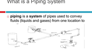
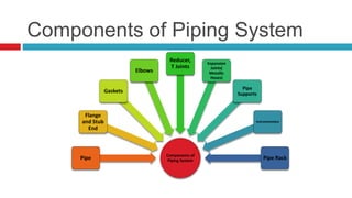
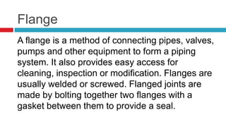
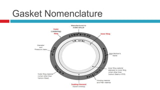
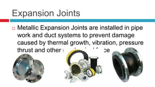
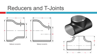
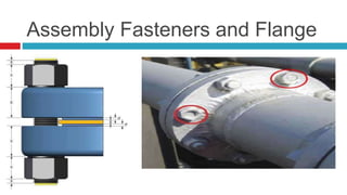
BASICS OF PIPING SYSTEM
INDEX
 What is Pipe System
 Pipe Components and Nomenclature
 Commonly Used MOCs
 References
What is a Piping System
 piping is a system of pipes used to convey
fluids (liquids and gases) from one location to
another.
Components of Piping System
Components of
Piping SystemPipe
Flange
and Stub
End
Gaskets
Elbows
Reducer,
T Joints
Expansion
Joints(
Metallic
Hoses)
Pipe
Supports
Instrumentation
Pipe Rack
Pipe
 Pipe is a hollow tube with round cross section
for the conveyance of products. The products
include fluids, gas, pellets, powders and more.
Nomenclature
 Nominal Pipe Size :
Nominal pipe size (NPS) is a dimensionless designator of pipe size. It indicates standard pipe size
when followed by the specific size designation number without an inch symbol. For example, NPS 6
indicates a pipe whose outside diameter is 168.3 mm.
 Schedule Number:
For a given NPS, the outside diameter stays constant and the wall thickness increases with larger
schedule number. The inside diameter will depend upon the pipe wall thickness specified by the
schedule number.
Schedule Number = 1,000 x (P/S)
where P = internal pressure, pounds-per-square-inch-gauge (psig)
S = allowable fiber stress (ultimate tensile strength of the steel in psi)
Stress Strain Curve
Type of Pipes
 LONGITUDINALLY WELDED SAW
 ELECTRIC RESISTANCE WELDED (ERW)
 SEAMLESS
Flange
A flange is a method of connecting pipes, valves,
pumps and other equipment to form a piping
system. It also provides easy access for
cleaning, inspection or modification. Flanges are
usually welded or screwed. Flanged joints are
made by bolting together two flanges with a
gasket between them to provide a seal.
Types of Flanges : Welded Neck, Slip On
1. Slip On flange 2. Filled weld outside
3. Filled weld inside 4. Pipe
1. Weld Neck flange 2. Butt Weld
3. Pipe or Fitting
Socket Welded and Lap Joint
Flange
1. Socket Weld flange 2. Filled weld 3. Pipe
X = Expansion gap
1. Lap Joint flange 2. Stub End
3. Butt weld 4. Pipe or Fitting
Threaded AND Blind Flange
1. Threaded flange 2. Thread 3.
Pipe or Fitting
1. Blind flange 2. Stud Bolt 3. Gasket 4.
Other flange
Gaskets
 Flange gaskets are used to create a static seal
between two flanges faces
 A gaskets fills the microscopic spaces and
irregularities of the flange faces, and then it
forms a seal that is designed to keep liquids
and gases
Semi Metallic
SEMI-METALLIC GASKETS are
composites of metal and non-metallic
materials.
• The metal is intended to offer strength
and resiliency, while the non-metallic
portion provides conformability and
sealability.
• Semi-metallic are designed for almost
all operating conditions and high-
temperature and pressure.
Non Metallic
• NON-METALLIC
GASKETS are usually
composite sheet materials
are used with flat-face and
raised-face flanges in low
Pressure Class applications.
• Non-metallic gaskets are
manufactured from arimid
fiber, glass fiber, elastomer,
Teflon® (PTFE), graphite etc.
Fasteners
ASME B1.1, included angle is 6
ASME B18.2.2,
Gasket Nomenclature
Expansion Joints
 Metallic Expansion Joints are installed in pipe
work and duct systems to prevent damage
caused by thermal growth, vibration, pressure
thrust and other mechanical forces.
Reducers and T-Joints
Assembly Fasteners and Flange
Material of Construction
 316 stainless has a unique chemical composition
which includes 16% chromium, 10% nickel and
2% molybdenum
 304 stainless has 18% chromium, 8% nickel and
no molybdenum
 Stainless steel certified to 316L or 304L will have
a maximum of 0.03% carbon, versus the 0.08%
maximum that regular 316 and 304 can have.
Pipe Racks
Racks shall be designed to give the piping shortest possible run and to provide clear head
rooms over main walkways, secondary walkways and platforms.
Predominantly process lines are to be kept at lower tier and utility & hot process lines on
upper tier.
Generally the top tier is to be kept for Electrical and Instrument cable trays.
Generally the hot lines and cold lines shall be kept apart in different groups on a tier.
Generally the bigger and heavier size lines shall be kept nearer to the column
References
ASME B31.1 Power piping.
ASME B31.3 Process piping.
API Std. 610 Centrifugal pumps for Petroleum, Heavy-duty chemical and gas Industry
service IBR Indian Boiler regulations
ASME SEC VII Rules for Construction of Pressure Vessels.
ASME B 16.5 Pipe Flanges
PIPING SYSTEM: Part 2
 Steam Piping
 Hot Oil Piping
 Pipe Supports
 Insulation, Radius of Insulation
 Heat Treatment of Metal
 Welding of Pipes
THANK YOU

Piping system presentation

  • 1.
  • 2.
    INDEX  What isPipe System  Pipe Components and Nomenclature  Commonly Used MOCs  References
  • 3.
    What is aPiping System  piping is a system of pipes used to convey fluids (liquids and gases) from one location to another.
  • 4.
    Components of PipingSystem Components of Piping SystemPipe Flange and Stub End Gaskets Elbows Reducer, T Joints Expansion Joints( Metallic Hoses) Pipe Supports Instrumentation Pipe Rack
  • 5.
    Pipe  Pipe isa hollow tube with round cross section for the conveyance of products. The products include fluids, gas, pellets, powders and more.
  • 6.
    Nomenclature  Nominal PipeSize : Nominal pipe size (NPS) is a dimensionless designator of pipe size. It indicates standard pipe size when followed by the specific size designation number without an inch symbol. For example, NPS 6 indicates a pipe whose outside diameter is 168.3 mm.  Schedule Number: For a given NPS, the outside diameter stays constant and the wall thickness increases with larger schedule number. The inside diameter will depend upon the pipe wall thickness specified by the schedule number. Schedule Number = 1,000 x (P/S) where P = internal pressure, pounds-per-square-inch-gauge (psig) S = allowable fiber stress (ultimate tensile strength of the steel in psi)
  • 7.
  • 8.
    Type of Pipes LONGITUDINALLY WELDED SAW  ELECTRIC RESISTANCE WELDED (ERW)  SEAMLESS
  • 9.
    Flange A flange isa method of connecting pipes, valves, pumps and other equipment to form a piping system. It also provides easy access for cleaning, inspection or modification. Flanges are usually welded or screwed. Flanged joints are made by bolting together two flanges with a gasket between them to provide a seal.
  • 10.
    Types of Flanges: Welded Neck, Slip On 1. Slip On flange 2. Filled weld outside 3. Filled weld inside 4. Pipe 1. Weld Neck flange 2. Butt Weld 3. Pipe or Fitting
  • 11.
    Socket Welded andLap Joint Flange 1. Socket Weld flange 2. Filled weld 3. Pipe X = Expansion gap 1. Lap Joint flange 2. Stub End 3. Butt weld 4. Pipe or Fitting
  • 12.
    Threaded AND BlindFlange 1. Threaded flange 2. Thread 3. Pipe or Fitting 1. Blind flange 2. Stud Bolt 3. Gasket 4. Other flange
  • 13.
    Gaskets  Flange gasketsare used to create a static seal between two flanges faces  A gaskets fills the microscopic spaces and irregularities of the flange faces, and then it forms a seal that is designed to keep liquids and gases
  • 14.
    Semi Metallic SEMI-METALLIC GASKETSare composites of metal and non-metallic materials. • The metal is intended to offer strength and resiliency, while the non-metallic portion provides conformability and sealability. • Semi-metallic are designed for almost all operating conditions and high- temperature and pressure.
  • 15.
    Non Metallic • NON-METALLIC GASKETSare usually composite sheet materials are used with flat-face and raised-face flanges in low Pressure Class applications. • Non-metallic gaskets are manufactured from arimid fiber, glass fiber, elastomer, Teflon® (PTFE), graphite etc.
  • 16.
    Fasteners ASME B1.1, includedangle is 6 ASME B18.2.2,
  • 17.
  • 18.
    Expansion Joints  MetallicExpansion Joints are installed in pipe work and duct systems to prevent damage caused by thermal growth, vibration, pressure thrust and other mechanical forces.
  • 19.
  • 20.
  • 21.
    Material of Construction 316 stainless has a unique chemical composition which includes 16% chromium, 10% nickel and 2% molybdenum  304 stainless has 18% chromium, 8% nickel and no molybdenum  Stainless steel certified to 316L or 304L will have a maximum of 0.03% carbon, versus the 0.08% maximum that regular 316 and 304 can have.
  • 22.
    Pipe Racks Racks shallbe designed to give the piping shortest possible run and to provide clear head rooms over main walkways, secondary walkways and platforms. Predominantly process lines are to be kept at lower tier and utility & hot process lines on upper tier. Generally the top tier is to be kept for Electrical and Instrument cable trays. Generally the hot lines and cold lines shall be kept apart in different groups on a tier. Generally the bigger and heavier size lines shall be kept nearer to the column
  • 23.
    References ASME B31.1 Powerpiping. ASME B31.3 Process piping. API Std. 610 Centrifugal pumps for Petroleum, Heavy-duty chemical and gas Industry service IBR Indian Boiler regulations ASME SEC VII Rules for Construction of Pressure Vessels. ASME B 16.5 Pipe Flanges
  • 24.
    PIPING SYSTEM: Part2  Steam Piping  Hot Oil Piping  Pipe Supports  Insulation, Radius of Insulation  Heat Treatment of Metal  Welding of Pipes
  • 25.