This document is a seminar report on intelligent variable valve timing and lift electronic control (i-VTEC) technology. It was submitted by a student to fulfill requirements for a bachelor's degree in mechanical engineering. The report provides background on i-VTEC, including its objectives, related terms, different VTEC systems, valve timing control, how the i-VTEC system works, advantages, disadvantages, and applications. It aims to explain this advanced internal combustion engine technology used in Honda vehicles.
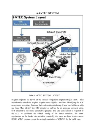
This pdf contains the multivalve engine description. the types of multivalve engine are also explain along with suitable pictures. the document gives idea the development in this technology today and market analysis
An i-VTEC is new technology introduce by the honda in the field of automobile. This technology is most famous and installed in all cars of the honda. In this presentation on i-VTEC you will find all about it like its working principle, its performance, its advantages and disadvantages and further development in this technology. A complete illustration about this technolgy is given in this presentation.
Electronic Power Steering (EPS) by Gaurav RaikarGauravRaikar3
This presentations describes electronic power steering types.
1.Hydraulic power steering system(HPS)
2.Electro-hydraulic power steering system(EHPS)
3.Electronic power system(EPS)
The heart of an automobile is its engine, and the heart requires a constant and ingenuous supply of blood, fuel in this case. There had been carburetors faithfully doing this holy work, but technology never seizes to move up. Therefore, the latest offering is the fuel injector for petrol engin es. Though it all started with a simple objective of supplying a controlled amount of fuel at proper intervals of time, it’s, as of now, not as simple as that. With emission norms getting stricter and changing trends in engine technology – high-speed engines, Variable displacement engines, Hybrid engines, etc – it became more and more of a necessity than a luxury to improve the fuel supply system.
Today’s fuel injection unit not only improves engine performance, but also helps in giving a cleaner exhaust that too with a increased fuel economy. The objectives can be attained using a microprocessor that directs the injector using a number of various input parameters. These parameters include manifold temperatures, throttle position, ignition timing, engine speed, load, and a lot more of other factors. The various strategically placed sensors measures these physical quantities and convey the same to the processor in electronic signals. The paper deals with the brief functionality and basic concept of operation of a modern fuel injector used in petrol engines.
Electronic Brake force distribution (EBFD)Felis Goja
EBD is an automobile brake technology that automatically varies the amount of force applied to each of a vehicle's wheels based on road conditions, speed, loading on wheel etc.
This presentation is made as per Dr. Babasaheb Ambedkar Technological University, lonere,Raigadh,Maharashtra. syllabus.
Useful for mechanical,automobile engineering students.
Electronic fuel injection vs carburettorsSalman Ahmed
These slides give you an idea of the different types of fuel injection systems that have been used throughout time.
A comparison between carburettors and EFI has been also looked on.
Our presentation attributes complete info regarding the three types of Drive by wire system i.e. Brake by wire, Electronic throttle control and Steer by wire system. Let’s find out how these 3 system works and what are the feasibilities & loopholes of Drive by wire system?
Introduction : Basic Feature of an Automobile
Car Body Details
Types of Vehicle
Body Engineering Terminology
Morphology of Vehicle Body ( Structural ) Design
Design Considerations
Rack And Pinion Mechanism for Continuous Variable Valve Timing of IC EnginesIJERA Editor
The valve timing is a very closely studied event and effects the performance of an IC Engine greatly with
respect to the Brake Power Produced, Volumetric Efficiency and Emissions etc. The valve event if varied and
experimented with, can result in higher efficiencies and overall improved performance of the Engine. Hence,
various researchers have attempted to temper with the valve timing and thus many Variable Valve Timing
systems have been proposed till date with many of them being implemented by various manufacturers.
However, on reviewing the presently employed systems, the lack of existence of a single system capable of
independently altering both the timing and the lift of the valves was recognized. Thus, a single system capable
of achieving the above was thought of and designed. A rack and pinion mechanism powered by a programmed
servo motor mounted vertically seemed most practical in achieving this within the size and space constraints. A
single cylinder diesel Engine was simulated with „Lotus Engine Simulation‟ software to derive the optimum
valve angles and lifts for a range of the Engine operating speed and the system was accordingly programmed
and designed to achieve them. The system was designed in „Creo‟ software and analysed correspondingly in
„Ansys‟ software and then finally assembled on a Diesel Engine in the lab.
it is a ppt on koenigsegg camless valves which are new inventions in ic engine here its principle and working have been explaned.and also working of conventional engine habe been explained.
This ppt is on evolution of vtec engines, also explains about the working of an engine along with explanation of an vtec engine.
This ppt on evolution of vtec engine published by HECTIC also briefs about the versions of vtec engines.
With the development of technologies such as VVT (Variable Valve Timing) and VVL (Variable Valve lift) controlled by ECU resulted in the development of modern ivtec, multiair and other advance engines which not only improved performance but also were energy efficient with less NOx emissions.
Saudi Arabia stands as a titan in the global energy landscape, renowned for its abundant oil and gas resources. It's the largest exporter of petroleum and holds some of the world's most significant reserves. Let's delve into the top 10 oil and gas projects shaping Saudi Arabia's energy future in 2024.
About
Indigenized remote control interface card suitable for MAFI system CCR equipment. Compatible for IDM8000 CCR. Backplane mounted serial and TCP/Ethernet communication module for CCR remote access. IDM 8000 CCR remote control on serial and TCP protocol.
• Remote control: Parallel or serial interface.
• Compatible with MAFI CCR system.
• Compatible with IDM8000 CCR.
• Compatible with Backplane mount serial communication.
• Compatible with commercial and Defence aviation CCR system.
• Remote control system for accessing CCR and allied system over serial or TCP.
• Indigenized local Support/presence in India.
• Easy in configuration using DIP switches.
Technical Specifications
Indigenized remote control interface card suitable for MAFI system CCR equipment. Compatible for IDM8000 CCR. Backplane mounted serial and TCP/Ethernet communication module for CCR remote access. IDM 8000 CCR remote control on serial and TCP protocol.
Key Features
Indigenized remote control interface card suitable for MAFI system CCR equipment. Compatible for IDM8000 CCR. Backplane mounted serial and TCP/Ethernet communication module for CCR remote access. IDM 8000 CCR remote control on serial and TCP protocol.
• Remote control: Parallel or serial interface
• Compatible with MAFI CCR system
• Copatiable with IDM8000 CCR
• Compatible with Backplane mount serial communication.
• Compatible with commercial and Defence aviation CCR system.
• Remote control system for accessing CCR and allied system over serial or TCP.
• Indigenized local Support/presence in India.
Application
• Remote control: Parallel or serial interface.
• Compatible with MAFI CCR system.
• Compatible with IDM8000 CCR.
• Compatible with Backplane mount serial communication.
• Compatible with commercial and Defence aviation CCR system.
• Remote control system for accessing CCR and allied system over serial or TCP.
• Indigenized local Support/presence in India.
• Easy in configuration using DIP switches.
Hybrid optimization of pumped hydro system and solar- Engr. Abdul-Azeez.pdffxintegritypublishin
Advancements in technology unveil a myriad of electrical and electronic breakthroughs geared towards efficiently harnessing limited resources to meet human energy demands. The optimization of hybrid solar PV panels and pumped hydro energy supply systems plays a pivotal role in utilizing natural resources effectively. This initiative not only benefits humanity but also fosters environmental sustainability. The study investigated the design optimization of these hybrid systems, focusing on understanding solar radiation patterns, identifying geographical influences on solar radiation, formulating a mathematical model for system optimization, and determining the optimal configuration of PV panels and pumped hydro storage. Through a comparative analysis approach and eight weeks of data collection, the study addressed key research questions related to solar radiation patterns and optimal system design. The findings highlighted regions with heightened solar radiation levels, showcasing substantial potential for power generation and emphasizing the system's efficiency. Optimizing system design significantly boosted power generation, promoted renewable energy utilization, and enhanced energy storage capacity. The study underscored the benefits of optimizing hybrid solar PV panels and pumped hydro energy supply systems for sustainable energy usage. Optimizing the design of solar PV panels and pumped hydro energy supply systems as examined across diverse climatic conditions in a developing country, not only enhances power generation but also improves the integration of renewable energy sources and boosts energy storage capacities, particularly beneficial for less economically prosperous regions. Additionally, the study provides valuable insights for advancing energy research in economically viable areas. Recommendations included conducting site-specific assessments, utilizing advanced modeling tools, implementing regular maintenance protocols, and enhancing communication among system components.
Student information management system project report ii.pdfKamal Acharya
Our project explains about the student management. This project mainly explains the various actions related to student details. This project shows some ease in adding, editing and deleting the student details. It also provides a less time consuming process for viewing, adding, editing and deleting the marks of the students.
NO1 Uk best vashikaran specialist in delhi vashikaran baba near me online vas...Amil Baba Dawood bangali
Contact with Dawood Bhai Just call on +92322-6382012 and we'll help you. We'll solve all your problems within 12 to 24 hours and with 101% guarantee and with astrology systematic. If you want to take any personal or professional advice then also you can call us on +92322-6382012 , ONLINE LOVE PROBLEM & Other all types of Daily Life Problem's.Then CALL or WHATSAPP us on +92322-6382012 and Get all these problems solutions here by Amil Baba DAWOOD BANGALI
#vashikaranspecialist #astrologer #palmistry #amliyaat #taweez #manpasandshadi #horoscope #spiritual #lovelife #lovespell #marriagespell#aamilbabainpakistan #amilbabainkarachi #powerfullblackmagicspell #kalajadumantarspecialist #realamilbaba #AmilbabainPakistan #astrologerincanada #astrologerindubai #lovespellsmaster #kalajaduspecialist #lovespellsthatwork #aamilbabainlahore#blackmagicformarriage #aamilbaba #kalajadu #kalailam #taweez #wazifaexpert #jadumantar #vashikaranspecialist #astrologer #palmistry #amliyaat #taweez #manpasandshadi #horoscope #spiritual #lovelife #lovespell #marriagespell#aamilbabainpakistan #amilbabainkarachi #powerfullblackmagicspell #kalajadumantarspecialist #realamilbaba #AmilbabainPakistan #astrologerincanada #astrologerindubai #lovespellsmaster #kalajaduspecialist #lovespellsthatwork #aamilbabainlahore #blackmagicforlove #blackmagicformarriage #aamilbaba #kalajadu #kalailam #taweez #wazifaexpert #jadumantar #vashikaranspecialist #astrologer #palmistry #amliyaat #taweez #manpasandshadi #horoscope #spiritual #lovelife #lovespell #marriagespell#aamilbabainpakistan #amilbabainkarachi #powerfullblackmagicspell #kalajadumantarspecialist #realamilbaba #AmilbabainPakistan #astrologerincanada #astrologerindubai #lovespellsmaster #kalajaduspecialist #lovespellsthatwork #aamilbabainlahore #Amilbabainuk #amilbabainspain #amilbabaindubai #Amilbabainnorway #amilbabainkrachi #amilbabainlahore #amilbabaingujranwalan #amilbabainislamabad
Automobile Management System Project Report.pdfKamal Acharya
The proposed project is developed to manage the automobile in the automobile dealer company. The main module in this project is login, automobile management, customer management, sales, complaints and reports. The first module is the login. The automobile showroom owner should login to the project for usage. The username and password are verified and if it is correct, next form opens. If the username and password are not correct, it shows the error message.
When a customer search for a automobile, if the automobile is available, they will be taken to a page that shows the details of the automobile including automobile name, automobile ID, quantity, price etc. “Automobile Management System” is useful for maintaining automobiles, customers effectively and hence helps for establishing good relation between customer and automobile organization. It contains various customized modules for effectively maintaining automobiles and stock information accurately and safely.
When the automobile is sold to the customer, stock will be reduced automatically. When a new purchase is made, stock will be increased automatically. While selecting automobiles for sale, the proposed software will automatically check for total number of available stock of that particular item, if the total stock of that particular item is less than 5, software will notify the user to purchase the particular item.
Also when the user tries to sale items which are not in stock, the system will prompt the user that the stock is not enough. Customers of this system can search for a automobile; can purchase a automobile easily by selecting fast. On the other hand the stock of automobiles can be maintained perfectly by the automobile shop manager overcoming the drawbacks of existing system.
Quality defects in TMT Bars, Possible causes and Potential Solutions.PrashantGoswami42
Maintaining high-quality standards in the production of TMT bars is crucial for ensuring structural integrity in construction. Addressing common defects through careful monitoring, standardized processes, and advanced technology can significantly improve the quality of TMT bars. Continuous training and adherence to quality control measures will also play a pivotal role in minimizing these defects.
TECHNICAL TRAINING MANUAL GENERAL FAMILIARIZATION COURSEDuvanRamosGarzon1
AIRCRAFT GENERAL
The Single Aisle is the most advanced family aircraft in service today, with fly-by-wire flight controls.
The A318, A319, A320 and A321 are twin-engine subsonic medium range aircraft.
The family offers a choice of engines
Water scarcity is the lack of fresh water resources to meet the standard water demand. There are two type of water scarcity. One is physical. The other is economic water scarcity.
CFD Simulation of By-pass Flow in a HRSG module by R&R Consult.pptxR&R Consult
CFD analysis is incredibly effective at solving mysteries and improving the performance of complex systems!
Here's a great example: At a large natural gas-fired power plant, where they use waste heat to generate steam and energy, they were puzzled that their boiler wasn't producing as much steam as expected.
R&R and Tetra Engineering Group Inc. were asked to solve the issue with reduced steam production.
An inspection had shown that a significant amount of hot flue gas was bypassing the boiler tubes, where the heat was supposed to be transferred.
R&R Consult conducted a CFD analysis, which revealed that 6.3% of the flue gas was bypassing the boiler tubes without transferring heat. The analysis also showed that the flue gas was instead being directed along the sides of the boiler and between the modules that were supposed to capture the heat. This was the cause of the reduced performance.
Based on our results, Tetra Engineering installed covering plates to reduce the bypass flow. This improved the boiler's performance and increased electricity production.
It is always satisfying when we can help solve complex challenges like this. Do your systems also need a check-up or optimization? Give us a call!
Work done in cooperation with James Malloy and David Moelling from Tetra Engineering.
More examples of our work https://www.r-r-consult.dk/en/cases-en/
Forklift Classes Overview by Intella PartsIntella Parts
Discover the different forklift classes and their specific applications. Learn how to choose the right forklift for your needs to ensure safety, efficiency, and compliance in your operations.
For more technical information, visit our website https://intellaparts.com
Explore the innovative world of trenchless pipe repair with our comprehensive guide, "The Benefits and Techniques of Trenchless Pipe Repair." This document delves into the modern methods of repairing underground pipes without the need for extensive excavation, highlighting the numerous advantages and the latest techniques used in the industry.
Learn about the cost savings, reduced environmental impact, and minimal disruption associated with trenchless technology. Discover detailed explanations of popular techniques such as pipe bursting, cured-in-place pipe (CIPP) lining, and directional drilling. Understand how these methods can be applied to various types of infrastructure, from residential plumbing to large-scale municipal systems.
Ideal for homeowners, contractors, engineers, and anyone interested in modern plumbing solutions, this guide provides valuable insights into why trenchless pipe repair is becoming the preferred choice for pipe rehabilitation. Stay informed about the latest advancements and best practices in the field.
The Benefits and Techniques of Trenchless Pipe Repair.pdf
I vtec report
1. i
A
SEMINAR REPORT
ON
“INTELLIGENT VARIABLE VALVE TIMING
AND LIFT ELECTRONIC CONTROL”
In Partial Fulfillment of the Requirements for the Degree of
Bachelor of Technology
In
Mechanical Engineering
Submitted by:
JABBAR
(1473640020)
Under the Supervision of
Mr. Savendra Pratap Singh
Department of Mechanical Engineering
RAJKIYA ENGINEERING COLLEGE,
AZAMGARH
(Affiliated to Dr. APJ Abdul Kalam Technical University, Lucknow & Approved by AICTE)
March, 2018
2. ii
CERTIFICATE
This is to certify that the report work entitled “INTELLIGENT VARIABLE
VALVE TIMING AND LIFT ELECTRONIC CONTROL” submitted in partial
fulfillment of the requirement for the degree of Bachelor of Technology in
“MECHANICAL ENGINEERING”, is a bonafide seminar work carried out by
JABBAR under my supervision and guidance.
Date: Mr. Savendra Pratap Singh
Mechanical Engineering department
REC, AZAMGARH
3. iii
ACKNOWLEDGEMENT
It is indeed a great pleasure to express our sincere thanks to our Seminar Guide
(Mr. Savendra Pratap Singh), Department of Mechanical Engineering of Rajkiya
Engineering College, Azamgarh for his continuous support in this project. He was
always there to listen and to give advice. He showed us different ways to approach a
research problem and the need to be persistent to accomplish any goal. He taught us
how to write academic paper, had confidence in us when we doubted ourselves, and
brought out the good ideas in us. He was always there to meet and talk about our ideas,
to proofread and mark up our paper, and to ask us good questions to help us think
through our problems. Without his encouragement and constant guidance, we could
not have finished this project.
Prof. S.P. Pandey, Director of Rajkiya Engineering College, Azamgarh, really
deserves our heartiest honour for providing us all the administrative support.
We are also indebted to our colleagues for their friendship, encouragement and
hard questions. Without their support and co-operation, this project could not have
been finished.
We are thankful to our family whose unfailing love, affection, sincere prayers and
best wishes had been a constant source of strength and encouragement.
4. ABSTRACT
The most important challenge facing car manufacturers today is to offer vehicles that
deliver excellent fuel efficiency and superb performance while maintaining cleaner
emissions and driving comfort. This paper deals with I-VTEC (intelligent-Variable
valve Timing and lift Electronic Control) engine technology which is one of the
advanced technology in the IC engine. I-VTEC is the new trend in Honda’s latest large
capacity four cylinder petrol engine family. The name is derived from ‘intelligent’
combustion control technologies that match outstanding fuel economy, cleaner
emissions and reduced weight with high output and greatly improved torque
characteristics in all speed range. The design cleverly combines the highly renowned
VTEC system - which varies the timing and amount of lift of the valves - with Variable
Timing Control. VTC is able to advance and retard inlet valve opening by altering the
phasing of the inlet camshaft to best match the engine load at any given moment. The
two systems work in concern under the close control of the engine management system
delivering improved cylinder charging and combustion efficiency, reduced intake
resistance, and improved exhaust gas recirculation among the benefits. I-VTEC
technology offers tremendous flexibility since it is able to fully maximize engine
potential over its complete range of operation. In short Honda's I-VTEC technology
gives us the best in vehicle performance.
5. CONTENTS
SR NO TOPIC NAME PAGE NO.
1. INDRODUCTION 1
2 OBJECTIVE 2
3. TERMS RELATED TO i-VTEC
3.1 Volumetric Efficiency
3.2 Torque
3.3 Power
3.4 Camshaft
3.5 Electronic ControlUnit (ECU)
3
4. VTEC
4.1 Basic VTEC Mechanism
4.2 DOHC VTEC
4.3 SOHC VTEC
4.4 3-Stage VTEC
5
5. VALVE TIMING CONTROL(VTC) 11
6. i-VTEC SYSTEM 12
7. ADVANTAGES OF i-VTEC SYSTEM 15
8. DISADVANTAGES OF i-VTEC 15
9. APPLICATIONS OF i-VTEC SYSTEM 15
10. CONCLUSION 16
11. REFERENCES 17
6. LIST OF FIGURES
FIGURE NO. DETAIL PAGE
NO.
Fig No:-2.1 ACTUAL DIAGRAM OF VALVE IN I-VTEC 3
Fig No:-4.1 VTEC OPERATION WITH GRAPH 6
Fig No:-4.2 BASIC VTEC PRINCIPLE 7
Fig No:-4.4 VTEC-E 9
Fig No:-4.5 THREE STAGES OF ACTUATION OF VALVES 10
Fig No:-6.1 I-VTEC SYSTEM LAYOUT 13
Fig No:-6.2 VALVE ACTUATION DIAGRAM 14
Fig No:-6.3 ACTUATION OF HIGH SPEED CAM 15
7. 1. INTRODUCTION
1.1 Definition
An internal combustion is defined “as an engine in which the chemical energy of
the fuel is released inside the engine and used directly for mechanical work‟. The
internal combustion engine was first conceived and developed in the late 1800‘s. The
man who is considered the inventor of the modern IC engine and the founder of the
industry is Nikolaus Otto (1832-1891).
1.2 Discovery
Over a century has elapsed since the discovery of IC engines. Excluding a few
development of rotary combustion engine the IC engines has still retained its basic
anatomy. As our knowledge of engine processes has increased, these engines have
continued to develop on a scientific basis. The present day engines have advances to
satisfy the strict environmental constraints and fuel economy standards in addition to
meeting in competitiveness of the world market.
With the availability of sophisticated computer and electronic, instrumentation have
added new refinement to the engine design. From the past few decades, automobile
industry has implemented many advance technologies to improve the efficiency and
fuel economy of the vehicle and i-VTEC engine introduced by Honda in its 2002
Acura RSX Type S is one of such recent trend in automobile industry. The VTEC
system provides the engine with multiple cam lobe profiles optimized for both low
and high RPM operations.
In basic form, the single barring shaft-lock of a conventional engine is replaced
with two profiles: one optimized for low-RPM stability and fuel efficiency, and the
other designed to maximize high-RPM power output. The switching operation
between the two cam lobes is controlled by the ECU which takes account of engine oil
pressure, engine temperature, vehicle speed, engine speed and throttle position. Using
these inputs, the ECU is programmed to switch from the low lift to the high lift cam
lobes when the conditions mean that engine output will be improved. At the switch
point a solenoid is actuated which allows oil pressure from a spool valve to operate a
locking pin which binds the high RPM cam follower to the low RPM ones. From this
point on, the valves open and close according to the high-lift profile, which opens the
valve further and for a longer time.
8. 2. OBJECTIVE
The objective of seminar report is;
1) To know the VTC system
2) To know the components
3) To understand the construction & working
4) Operations
9. i-VTEC SYSTEM
The latest and most sophisticated VTEC development is i-VTEC ("intelligent"
VTEC), which combines features of all the various previous VTEC systems for even
greater power band width and cleaner emissions. With the latest i-VTEC setup, at low
rpm the timing of the intake valves is now staggered and their lift is asymmetric,
which creates a swirl effect within the combustion chambers. At high rpm, the VTEC
transitions as previously into a high-lift, long-duration cam profile. The i-VTEC
system utilizes Honda's proprietary VTEC system and adds VTC (Variable Timing
Control), which allows for dynamic/continuous intake valve timing and overlap
control. The demanding aspects of fuel economy, ample torque, and clean emissions
can all be controlled and provided at a higher level with VTEC (intake valve timing
and lift control) and VTC (valve overlap control) combined. The i stands for
intelligent: i-VTEC is intelligent-VTEC. Honda introduced many new innovations in
i-VTEC, but the most significant one is the addition of a variable valve opening
overlap mechanism to the VTEC system. Named VTC for Variable Timing Control,
the current (initial) implementation is on the intake camshaft and allows the valve
opening overlap between the intake and exhaust valves to be continuously varied
during engine operation.
FIG.2.1-ACTUAL DIAGRAM OF VALVE IN I-VTEC
10. 3. TERMS RELATED TO i-VTEC:
3.1 Volumetric Efficiency
The engine produces a certain force from every power stroke as a result of burning
air/fuel expanding. This force generally gets less for every power stroke as the engine
revolves faster, as the air/fuel mixture has less time to get sucked into the cylinder.
The volumetric efficiency of a engine at a certain speed is the pressure of air/fuel
mixture inside the cylinder when the piston has finished sucking in the mixture, as a
percentage of the atmospheric pressure. Thus an engine with 80% volumetric
efficiency at a certain speed will have a mixture pressure of 80% of atmospheric
pressure when the piston is at bottom dead centre after the intake stroke.
3.2 Torque
The torque of an engine is the total force the engine produces at a certain speed.
This is a rotating force, but the easiest way to think of torque is to imagine an engine
with a drum attached to it, winching up a weight vertically. The torque of the engine is
the force that raises the weight The torque of an engine will increase as the engine
rotates faster, because the number of power strokes per time period increases.
However, the volumetric efficiency of an engine will drop after a certain speed, so
each power stroke has less force. The point where the increase in force (from the
increased number of power strokes) is equal to the drop in force (because of less
efficiency) is the point of peak torque. This occurs anywhere from 2000 - 7000 rpm,
depending on the engine. A higher performance engine will generally have a higher
efficiency and maintain this longer, so will have peak torque at higher revs. In the case
of my B16A VTEC engine, the torque peak is at about 7000 rpm, which is one of the
highest of any mass produced vehicle engine.
3.3 Power
The gearbox modifies torque from the engine to torque at the wheels. If one engine
produces the same torque as another, but at a higher engine speed, then force at the
wheels will be higher for the first engine one the engine speed is converted by the
gearbox to the same wheel speed. The power of an engine is the measurement of the
torque of an engine at different engine speeds. Going back to our engine winching
analogy, it is easy to see that if the engine is geared down so that the drum rotates half
as fast, then weight will be raised slower be more weight can be lifted. The peak
power point for an engine is the point where, ideally geared, the most force will be
available at the wheels. The peak power point will always be above the peak torque
point. In my B16A engine, the peak power occurs at about 7800 rpm
11. 3.4 The Camshaft
The camshaft has a very big influence on engine breathing. The camshaft controls
how long the intake and exhaust valves are open, and how high they open. The intake
valves always open before the piston is at the top of the cylinder (and started sucking)
and close after the piston is at the bottom of the cylinder (and stopped sucking). The
shape of the cam lobes limits the valve opening and closing to a gradual opening from
closed to fully open, then a gradual closing to fully shut. (Otherwise the value train
will destroy itself at high speeds) So while the value opens before the cylinder is
sucking, it is not open that much. There is a trade off in terms of efficiency with the
camshaft. It is possible to open the values earlier, and have the valve open further for a
longer period while the engine is sucking in mixture (it works the same for the
exhaust). The valve will be open before the piston has reached the top of the cylinder,
and some of the mixture will be pushed out of the cylinder but the piston. Because of
the momentum effect of the intake mixture, this loss is less at higher revs, and more at
lower speeds, when the intake mixture has not much momentum to overcome mixture
being forced out of the cylinder. A camshaft that opens the values early and closes
them late (called long duration, or wild or lumpy) will be more efficient at higher
engine speeds and less efficient at lower engine speeds. A camshaft that opens later
and closes earlier (called short duration, or mild) will be more efficient at lower
engine speeds and less efficient at higher engine speeds.
3.5 ECU
The ECU (electronic control unit = the fuel injection computer) is the heart of the
engine. Basically the purpose of the ECU is to control fuel injection and ignition for
the engine, for all the conditions which the engine can be expected to run under. This
is a fairly complicated job considering the number of external factors that can
influence the amount of fuel that needs to be injected into the engine, and the rate at
which events happen. At 8500 rpm the ECU has to control 280 injector
openings/closing per second and 280 ignition signals per second, while coping with
2400 signals from the distributor per second. Plus there are another 16-odd signals and
sensor reading from the engine and outside world that ECU needs to know about.
12. 4. VTEC ENGINE
VTEC (standing for Variable valve Timing and lift Electronic Control) does Honda
Motor Co., Ltd. develop a system. The principle of the VTEC system is to optimize
the amount of air-fuel charge entering, and the amount of exhaust gas leaving, the
cylinders over the complete range of engine speed to provide good top-end output
together with low and mid-range flexibility. VTEC system is a simple and fairly
elegant method of endowing the engine with multiple camshaft profiles optimized for
low and high RPM operations. Instead of only one cam lobe actuating each valve,
there are two - one optimized for low RPM smoothness and one to maximize high
RPM power output. Switching between the two cam lobes is controlled by the
engine's management computer. As the engine speed is increased, more air/fuel
mixture needs to be "inhaled" and "exhaled" by the engine. Thus to sustain high
engine speeds, the intake and exhaust valves needs to open nice and wide. As engine
RPM increases, a locking pin is pushed by oil pressure to bind the high RPM cam
follower for operation. From this point on, the valve opens and closes according to the
high-speed profile, which opens the valve further and for a longer time.
4.1 BASIC V-TEC MECHANISM
The basic mechanism used by the VTEC technology is a simple hydraulically
actuated pin. This pin is hydraulically pushed horizontally to link up adjacent rocker
arms. A spring mechanism is used to return the pin back to its original position. To
start on the basic principle, examine the simple diagram below. It comprises a
camshaft with two cam-lobes side-by-side. These lobes drive two side-by-side valve
rocker arms.
FIG.4.1 VTEC OPERATION WITH GRAPH
13. The two cam/rocker pairs operates independently of each other. One of the two cam-
lobes are intentionally drawn to be different. The one on the left has a "wilder" profile,
it will open its valve earlier, open it more, and close it later, compared to the one on
the right. Under normal operation, each pair of cam-lobe/rocker-arm assembly will
work independently of each other. VTEC uses the pin actuation mechanism to link the
mild-cam rocker arm to the wild-cam rocker arm. This effectively makes the two
rocker arms operate as one. This "composite" rocker arm(s) now clearly follows the
wild-cam profile of the left rocker arm. This in essence is the basic working principle
of all of Honda's VTEC engines. VTEC, the original Honda variable valve control
system, originated from REV (Revolution-modulated valve control) introduced on the
CBR400 in 1983 known as HYPER VTEC. In the regular four-stroke automobile
engine, the intake and exhaust valves are actuated by lobes on a camshaft. The shape
of the lobes determines the timing, lift and duration of each valve. Timing refers to an
angle measurement of when a valve is opened or closed with respect to the piston
position (BTDC or ATDC). Lift refers to how much the valve is opened. Duration
refers to how long the valve is kept open. Due to the behavior of the working fluid (air
and fuel mixture) before and after combustion, which have physical limitations on
their flow, as well as their interaction with the ignition spark, the optimal valve
timing, lift and duration settings under low RPM engine operations are very different
from those under high RPM. Optimal low RPM valve timing, lift and duration settings
would result in insufficient filling of the cylinder with fuel and air at high RPM, thus
greatly limiting engine power output. Conversely, optimal high RPM valve timing, lift
and duration settings would result in very rough low RPM operation and difficult
idling. The ideal engine would have fully variable valve timing, lift and duration, in
which the valves would always open at exactly the right point, lift high enough and
stay open just the right amount of time for the engine speed in use.
FIG. 4.2-BASIC VTEC PRINCIPLE
14. 4.2 DOHC VTEC
Introduced as a DOHC (Double overhead camshaft) system in Japan in the 1989
Honda Integra XSi this used the 160 bhp (120 kW) B16A engine. The same year,
Europe saw the arrival of VTEC in the Honda CRX 1.6i-VT, using a 150 bhp variant
(B16A1). The United States market saw the first VTEC system with the introduction
of the 1991 Acura NSX, which used a 3-litre DOHC VTEC V6 with 270 bhp (200
kW). DOHC VTEC engines soon appeared in other vehicles, such as the 1992 Acura
Integra GS-R (B17A1 1.7-litre engine), and later in the 1993 Honda Prelude VTEC
(H22A 2.2-litre engine with 195 hp) and Honda Del Sol VTEC (B16A3 1.6-litre
engine). The Integra Type R (1995–2000) available in the Japanese market produces
197 bhp (147 kW; 200 PS) using a B18C5 1.8-litre engine, producing more
horsepower per liter than most super-cars at the time. Honda has also continued to
develop other varieties and today offers several varieties of VTEC, such as i-VTEC
and i-VTEC Hybrid.
4.3 SOHC VTEC
As popularity and marketing value of the VTEC system grew, Honda applied the
system to SOHC (single overhead camshaft) engines, which share a common camshaft
for both intake and exhaust valves. The trade-off was that Honda's SOHC engines
benefitted from the VTEC mechanism only on the intake valves. This is because
VTEC requires a third center rocker arm and cam lobe (for each intake and exhaust
side), and, in the SOHC engine, the spark plugs are situated between the two exhaust
rocker arms, leaving no room for the VTEC rocker arm. Additionally, the center lobe
on the camshaft cannot be utilized by both the intake and the exhaust, limiting the
VTEC feature to one side.
However, beginning with the J37A4 3.7L SOHC V6 engine introduced on all 2009
Acura TL SH-AWD models, SOHC VTEC was incorporated for use with intake and
exhaust valves. The intake and exhaust rocker shafts contain primary and secondary
intake and exhaustrocker arms, respectively. The primary rocker arm contains the
VTEC switching piston, while the secondary rocker arm contains the return spring.
The term "primary" does not refer to which rocker arm forces the valve down during
low-RPM engine operation. Rather, it refers to the rocker arm which contains the
VTEC switching piston and receives oil from the rocker shaft.
The primary exhaust rocker arm contacts a low-profile camshaft lobe during low
RPM engine operation. Once VTEC engagement occurs, the oil pressure flowing from
the exhaust rocker shaft into the primary exhaust rocker arm forces the VTEC
switching piston into the secondary exhaust rocker arm, thereby locking both exhaust
rocker arms together. The high profile camshaft lobe which normally contacts the
15. secondary exhaust rocker arm alone during low-RPM engine operation is able to move
both exhaust rocker arms together which are locked as a unit. The same occurs for the
intake rocker shaft, except that the high-profile camshaft lobe operates the primary
rocker arm.
The difficulty of incorporating VTEC for both the intake and exhaust valves in a
SOHC engine has been removed on the J37A4 by a novel design of the intake rocker
arm. Each exhaust valve on the J37A4 corresponds to one primary and one secondary
exhaust rocker arm. Therefore, there are a total of twelve primary exhaust rocker arms
and twelve secondary exhaust rocker arms. However, each secondary intake rocker
arm is shaped similar to a "Y" which allows it to contact two intake valves at once.
One primary intake rocker arm corresponds to each secondary intake rocker arm. As a
result of this design, there are only six primary intake rocker arms and six secondary
intake rocker arms.
4.4 VTEC-E
FIG.4.4 VTEC-E
The earliest VTEC-E implementation is a variation of SOHC VTEC which is used to
increase combustion efficiency at low RPM while maintaining the mid range
performance of non-VTEC engines. VTEC-E is the first version of VTEC to employ
the use of roller rocker arms and because of that, it forgoes the need for having 3
intake lobes for actuating the two valves—
two identical lobes for non-VTEC operation and one lobe for VTEC operation.
Instead, there are two different intake cam profiles per cylinder—a very mild cam lobe
with little lift and a normal cam lobe with moderate lift. Because of this, at low RPM,
when VTEC is not engaged, one of the two intake valves is allowed to open only a
very small amount due to the mild cam lobe, forcing most of the intake charge through
the other open intake valve with the normal cam lobe. This induces swirl of the intake
16. charge which improves air/fuel atomization in the cylinder and allows for a leaner fuel
mixture to be used. As the engine's speed and load increase, both valves are needed to
supply a sufficient mixture. When engaging VTEC mode, a pre-defined threshold for
MPH (must be moving), RPM and load must be met before the computer actuates a
solenoid which directs pressurized oil into a sliding pin, just like with the original
VTEC. This sliding pin connects the intake rocker arm followers together so that now,
both intake valves are now following the "normal" camshaft lobe instead of just one of
them. When in VTEC, since the "normal" cam lobe has the same timing and lift as the
intake cam lobes of the SOHC non-VTEC engines, both engines have identical
performance in the upper power band assuming everything else is the same.
With the later VTEC-E implementations, the only difference it has with the earlier
VTEC-E is that the second "normal" cam profile has been replaced with a "wild" cam
profile which is identical to the original VTEC "wild" cam profile. This in essence
supersedes VTEC and the earlier VTEC-E implementations since the fuel and low
RPM torque benefits of the earlier VTEC-E are combined with the high performance
of the original VTEC.
4.5 3-STAGES VTEC
FIG. 4.5 THREE STAGES OF ACTUATION OF VALVES
3-Stage VTEC is a version that employs three different cam profiles to control intake
valve timing and lift. Due to this version of VTEC being designed around a SOHC
valve head, space was limited and so VTEC can only modify the opening and closing
of the intake valves. The low-end fuel economy improvements of VTEC-E and the
performance of conventional VTEC are combined in this application. From idle to
2500-3000 RPM, depending on load conditions, one intake valve fully opens while
the other opens just slightly, enough to prevent pooling of fuel behind the valve, also
called 12-valve mode. This 12 Valve mode results in swirl of the intake charge which
17. increases combustion efficiency, resulting in improved low end torque and better fuel
economy. At 3000-5400 RPM, depending on load, one of the VTEC solenoids
engages, which causes the second valve to lock onto the first valve's camshaft lobe.
Also called 4-valve mode, this method resembles a normal engine operating mode and
improves the mid-range power curve. At 5500-7000 RPM, the second VTEC solenoid
engages (both solenoids now engaged) so that both intake valves are using a middle,
third camshaft lobe. The third lobe is tuned for high-performance and provides peak
power at the top end of the RPM range.
VTEC system which combines the standard VTEC and VTEC-E concepts to
create a high power, fuel efficient valve train.
Utilizes 3 separate Camshaft Profiles. This system operates like VTEC-E
closing one valve at low speeds and then opening both valves at a standard lift
and duration at a midrange rpm. It then has a high rpm cam which opens both
valves aggressively as in standard VTEC.
Like standard VTEC one rocker arm, usually on the highest lift profile, is not
attached to a valve so that the highest lift is only used when the system is in
operational VTEC range.
In the illustration below the three significant camshaft profiles can be seen.
And the sliding pins for each stage are shown as well.
18. 5. VARIABLE TIMING CONTROL (VTC)
VTC operating principle is basically that of the generic variable valve timing
implementation (this generic implementation is also used by Toyota in their VVT-i
and BMW in their VANOS/double-VANOS system). The generic variable valve
timing implementation makes use of a mechanism attached between the cam sprocket
and the camshaft. This mechanism has a helical gear link to the sprocket and can be
moved relative the sprocket via hydraulic means. When moved, the helical gearing
effectively rotates the gear in relation to the sprocket and thus the camshaft as well.
The drawing above serves to illustrate the basic operating principle of VTC (and
generic variable valve timing). A labels the cam sprocket (or cam gear) which the
timing belt drives. Normally the camshaft is bolted directly to the sprocket. However
in VTC, an intermediate gear is used to connect the sprocket to the camshaft. This
gear, labeled B has helical gears on its outside. As shown in the drawing, this gear
links to the main sprocket which has matching helical gears on the inside. The cam
shaft, labeled C attaches to the intermediate gear. The supplementary diagram on the
right shows what happens when we move the intermediate gear along its holder in the
cam sprocket. Because of the interlinking helical gears, the intermediate gear will
rotate along its axis if moved. Now, since the camshaft is attached to this gear, the
camshaft will rotate on its axis too. What we have achieved now is that we have move
the relative alignment between the camshaft and the driving cam-sprocket - we have
changed the cam timing.
19. 6. i-VTEC SYSTEM
FIG.6.1 I-VTEC SYSTEM LAYOUT
Diagram explains the layout of the various components implementing i-VTEC. I have
intentionally edited the original diagram very slightly - the lines identifying the VTC
components are rather faint and their orientation confusing. I have overlaid them with
red lines. They identify the VTC actuator as well as the oil pressure solenoid valve,
both attached to the intake camshaft's sprocket. The VTC cam sensor is required by
the ECU to determine the current timing of the intake camshaft. The VTEC
mechanism on the intake cam remains essentially the same as those in the current
DOHC VTEC engines except for an implementation of VTEC-E for the 'mild' cam.
20. FIG.6.2-VALVE ACTUATION DIAGRAM
The diagrams show that VTEC is implemented only on the intake cam. Now, note that
there is an annotation indicating a 'mostly resting (intake) cam' in variations 1 to 3.
This is the 'approximately 1-valve' operating principle of VTEC-E. i.e. one intake
valve is hardly driven while the other opens in its full glory. This instills a swirl effect
on the air-flow which helps in air-fuel mixture and allows the use of the crazy 20+ to
1 air-to-fuel ratio in lean-burn or economy mode during idle running conditions. On
first acquaintance, variations 1 and 3 seem identical. However, in reality they
represent two different engine configurations - electronic-wise. Variation 1 is lean
burn mode, the state in which the ECU uses >20:1 air-fuel ratio. VTC closes the
intake/exhaust valve overlap to a minimal. Note that lean-burn mode or variation 1 is
used only for very light throttle operations as identified by the full load Torque curve
overlaid on the VTC/RPM graph. During heavy throttle runs, the ECU goes into
variation 3 Lean-burn mode is contained within variation-2 as a dotted area probably
for the reason that the ECU bounces to and-fro between the two modes depending on
engine rpm, throttle pressure and engine load, just like the 3-stage VTEC D15B and
D17A. In variation-2, the ECU pops out of lean-burn mode, goes back to 14.7 or 12 to
1 air-fuel ratios and brings the intake/exhaust overlap right up to maximum. This as
Honda explains will induce the EGR effect, which makes use of exhaust gases to
reduce emissions. Variation-3 is the mode where the ECU varies intake/exhaust
opening overlap dynamically based on engine rpm for heavy throttle runs but low
engine revs. Note also that variations 1 to 3 are used in what Honda loosely terms the
idle rpm. For 3-stage VTEC engines, idle rpms take on a much broader meaning. It is
no longer the steady 750 rpm or so for an engine at rest. For 3-stage VTEC, idle rpm
21. also means low running rpm during ideal operating conditions, i.e. closed or very
narrow throttle positions, flat even roads, steady speed, etc. It is an idle rpm range.
The K20A engine implements this as well.
FIG.6.3-ACTUATION OF HIGH SPEED CAM
Variation-4 is activated whenever rpm rises and throttle pressure increases, indicating
a sense of urgency as conveyed by the driver's right foot. This mode sees the wild
cams of the intake camshaft being activated, the engine goes into 16-valve mode now
and VTC dynamically varies the intake camshaft to provide optimum intake/exhaust
valve overlap for power.
On i-VTEC engines, the engine computer also monitors cam position, intake
manifold pressure, and engine rpm, then commands the VTC (variable timing control)
actuator to advance or retard the cam. At idle, the intake cam is almost fully retarded
to deliver a stable idle and reduce oxides of nitrogen (NOX) emissions. The intake
cam is progressively advanced as rpm builds, so the intake valves open sooner and
valve overlap increases. This reduces pumping losses, increasing fuel economy while
further reducing exhaust emissions due to the creation of an internal exhaust gas
recirculation (EGR) effect.
i-VTEC introduced continuously variable timing, which allowed it to have more
than two profiles for timing and lift, which was the limitation of previous systems.
The valve lift is still a 2-stage setup as before, but the camshaft is now rotated via
hydraulic control to advance or retard valve timing. The effect is further optimization
of torque output, especially at low RPMs.
Increased performance is one advantage of the i-VTEC system. The torque curve is
"flatter" and does not exhibit any dips in torque that previous VTEC engines had
22. without variable camshaft timing. Horsepower output is up, but so is fuel economy.
Optimizing combustion with high swirl induction makes these engines even more
efficient. Finally, one unnoticed but major advantage of i-VTEC is the reduction in
engine emissions. High swirl intake and better combustion allows more precise air-
fuel ratio control. This results in substantially reduced emissions, particularly NOx.
Variable control of camshaft timing has allowed Honda to eliminate the EGR system.
Exhaust gases are now retained in the cylinder when necessary by changing camshaft
timing. This also reduces emissions without hindering performance.
7. ADVANTAGES OF i-VTEC
1) Better Fuel Efficiency.
2) High initial torque and relevant high power.
3) Lower emission.
4) Strong performance.
8. DISADVANRAGES OF i-VTEC
1) Cost is high.
2) Available in Honda Models only.
9. APPLICATIONS
Currently i-VTEC technology is available In Honda products;
1) Honda CRV
2) Honda CITY
3) Honda Civic
4) Honda Amaze
5) Honda Accord
23. 10.CONCLUSION
1. i-VTEC system is more sophisticated than earlier variable-valve-timing systems,
which could only change the time both valves are open during the intake/exhaust
overlap period on the transition between the exhaust and induction strokes.
2. By contrast, the i-VTEC setup can alter both camshaft duration and valve lift. i-
VTEC Technology gives us the best in vehicle performance.
3. Fuel economy is increased, emissions are reduced, derivability is enhanced and
power is improved.
24. 11. REFERENCES
Deccan Honda, Service Centre, Waluj Aurangabad.
Mr. Santosh Gade (service manager Deccan Honda)
Mr. Bodkhe Sir (worker) d. Wikipedia,
(www.wikipedia.com/ivtec)
Street Magazine, (www.streetmagazine.com)
Delphi Variable Cam Phases. 2014. 1 May 2014
http://www.delphi.com/manufacturers/auto/powertrain/gas/valvetrain/vcp/ i.
VANOS. 2007. 1 May 2007. http://www.bmw.dk/teknisk/en_artikkel.asp?id=5
Different Types of VVT. 2005. 3 May 2014.
http://www.autozine.org/technical_school/engine/vvt_2.htm
Honda Worldwide. 2014. 1 May 2014.
http://world.honda.com/motorcycletechnology/vtec/img/p3_04.jpg
VTEC 2014. 1 May
2014.http://www.lukkorbmacher.de/Autos/Technik/vtec.html