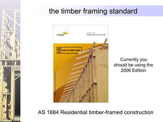
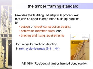
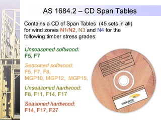
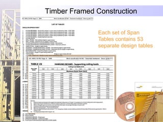
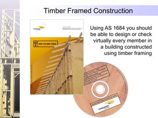
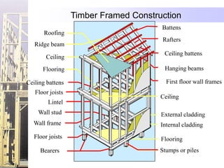
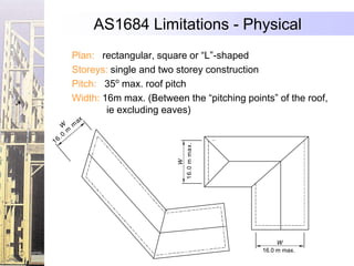
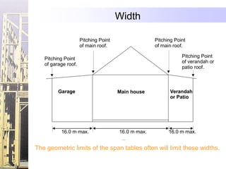
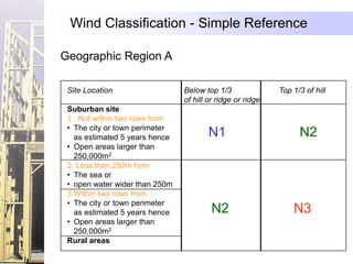
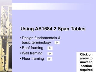
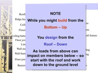
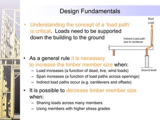
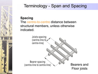
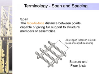
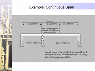
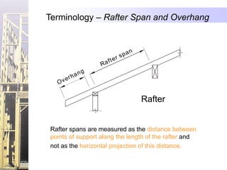
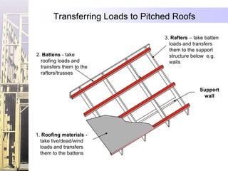
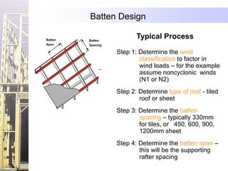
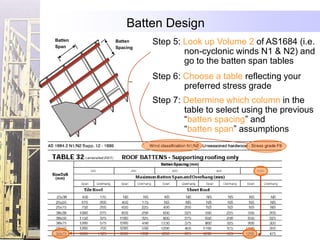
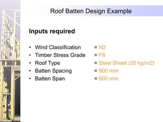
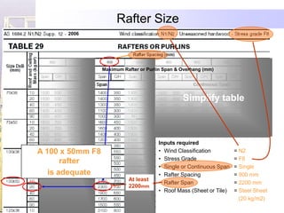
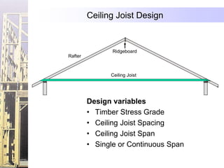
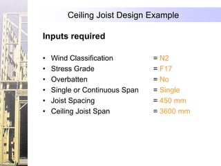
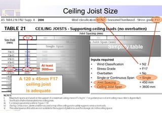
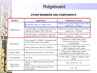
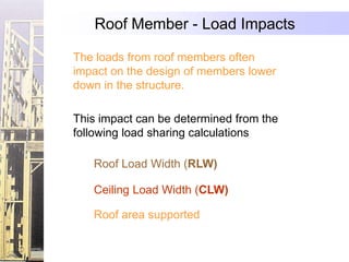
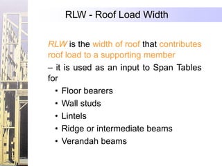
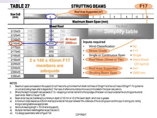
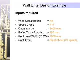
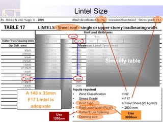
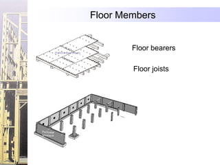
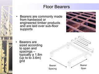
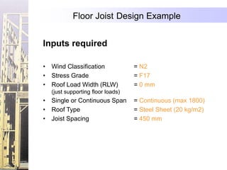
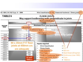
AS1684 provides guidance for timber framed construction in non-cyclonic areas. It contains span tables to help size timber members for roofs, walls, and floors based on wind zone and timber grade. Designers should start at the roof and work down, considering load paths and increasing member sizes for longer spans or indirect loads. Span refers to the distance between supports, while spacing is the distance between member centerlines.
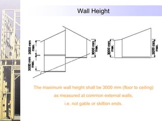
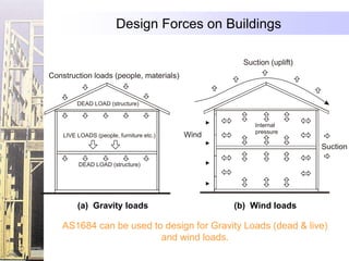
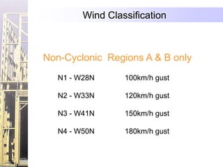
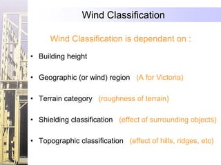
Timber Design to AS1720.1 (+Amdt 3, 2010) Webinar - ClearCalcsClearCalcs
Understanding the complete timber design process and the
key differences with wood design using AS 1720.1 or AS 1684.
ClearCalcs engineering development lead Brooks Smith gave this free engineering webinar covering Timber Design to AS1720.1, including a discussion of common design parameters and considerations, a comparison with the residentially geared AS1720.3 and AS1684, as well as worked examples using the AS 1720.1 calculator in ClearCalcs.
Long a mainstay in residential construction due to its versatility, cost, and environmental friendliness, timber is now seeing growing demand in mid rise structures thanks to growing understanding of how to utilise the material, as well as the continued rise in availability of engineered wood products (EWP) such as glue laminated and cross laminated timbers.
However, unlike steel whose properties tend to remain fairly constant over time, timber has a range of factors that need to be considered by engineers including moisture content, creep, and load duration factors.
Wind Design to AS/NZ 1170.2 Webinar Slides - ClearCalcsClearCalcs
Technical webinar discussing wind design to Australian and New Zealand Wind Standard 1170.2-2011 including a discussion of key design parameters, modification factors, notable clauses, and worked examples for a simple omni-directional design and a complex multi-directional terrain design.
Try out the AS1170.2 Wind Calculator now available at ClearCalcs.com
Webinar recording available at:
https://vimeo.com/350649576
Worked Examples for Timber Beam Design to AS1720.1 WebinarClearCalcs
Supporting worked examples for the ClearCalcs timber beam design webinar. Included examples cover a simply supported and complex wood beam designed using the ClearCalcs AS1720.1 calculator.
Designing a Concrete Beam Using the New AS3600:2018 - Webinar Slides - ClearC...ClearCalcs
The 2018 revision of the AS3600 Concrete standard includes major revisions for areas including phi factors, shear, deflection, rectangular stress block, and shrinkage/creep.
In this webinar, ClearCalcs lead engineering developer Brooks Smith discusses some of these key changes, and runs through the design process for a concrete beam design before demonstrating a few worked examples using AS3600:2018 in the newly released rectangular concrete beam calculator on ClearCalcs.com.
Watch the recorded webinar: https://vimeo.com/295532300
Explore all of our concrete, timber, and steel calculations at clearcalcs.com.
AS4100 Steel Design Webinar Worked ExamplesClearCalcs
Worked examples from the ClearCalcs AS4100 Steel Design Webinar - slides: https://www.slideshare.net/clearcalcs/steel-design-to-as4100-1998-a12016-webinar-clearcalcs
Designing a Cold-Formed Steel Beam Using AS4600:2018 and 2005 - WebinarClearCalcs
Recording: https://vimeo.com/318370452
Cold-formed and light gauge steel are rapidly growing in use across residential and commercial projects thanks to their cost-effective and customisable nature.
In this presentation, ClearCalcs engineer Brooks Smith discusses what makes CFS unique, how to design a cold-formed beam to the newly released AS4600:2018, and key differences between the older 2005 version of the standard - most notably the new preference for the use of the Direct Strength Method over the Effective Width Method.
• A retaining wall construction method in which walls are constructed with small gaps between adjacent piles. The size of the space is determined by the nature of the soils.
• الخوازيق الساندة بيتم تنفيذها قبل حفر الموقع لأن وظيفتها سند جوانب الحفر
ولايتم الحفر قبل مرور 28 يوم على تنفيذ آخر خازوق ساند
• وبيتم استخدام الخوازيق البنتونيت فى حالة وجود مياة جوفية بمنسوب أعلى ممنسوب الحفرن
• وبيتم تنفيذ الخوازيق البنتونيت أولا ثم بين كل خازوقين بنتونيت يتم تنفيذ خازوق خرسانى بحيث يتداخل بالخوازيق البنتونيت أثناءالتنفي ولا تأثير انشائي له سواء الاملاء وسند التربة
This document presents an example of analysis design of slab using ETABS. This example examines a simple single story building, which is regular in plan and elevation. It is examining and compares the calculated ultimate moment from CSI ETABS & SAFE with hand calculation. Moment coefficients were used to calculate the ultimate moment. However it is good practice that such hand analysis methods are used to verify the output of more sophisticated methods.
Also, this document contains simple procedure (step-by-step) of how to design solid slab according to Eurocode 2.The process of designing elements will not be revolutionised as a result of using Eurocode 2. Due to time constraints and knowledge, I may not be able to address the whole issues.
ANALYSIS AND DESIGN OF HIGH RISE BUILDING BY USING ETABSila vamsi krishna
RESULT OF ANALYSIS:
https://www.slideshare.net/ilavamsikrishna/results-of-etabs-on-high-rise-residential-buildings
ANALYSIS AND DESIGN OF BUILDING BY USING STAAD PRO PPT link :
https://www.slideshare.net/ilavamsikrishna/analysis-and-design-of-mutistoried-residential-building-by-using-staad-pro
FOR FULL REPORT:
vamsiila@gmail.com
In order to view this Chapter 3 Building Construction Jeopardy in game format, you must download and then view as Slide Show in PowerPoint format. If you do not have PowerPoint, you can download PowerPoint Viewer by going to www.microsoft.com, under Microsoft "Home and Office" choose PowerPoint Viewer 2003
different types of paint, 10 different types of paint, acrylic paint , automotive paint, epoxy paint, emulsion paint, enamel paint, concrete paint, eggshell paint, latex paint, metallic paint, texture paint, who introduced acrylic paint, types of automotive paint, ingredients used in concrete paint, paint types in India, paint types in US
While Designing a High rise Load & Structural Analysis is major factor to consider. Here we analyzed some data and try to describe briefly. We hope that it will help you lot :) Done by Neeti Lamic, Bayezid, Sykot Hasan
Retaining walls are a fantastic way to add a visual impact to your home garden or office surroundings. choose the best suitable retaining wall design for your garden or any other site.
1. Understanding Residential Timber
AS1684 Framed Construction
Timber Framing
Using AS 1684.2 Span Tables
2. the timber framing standard
Currently you
should be using the
2006 Edition
AS 1684 Residential timber-framed construction
3. the timber framing standard
Provides the building industry with procedures
that can be used to determine building practice,
to
• design or check construction details,
• determine member sizes, and
• bracing and fixing requirements
for timber framed construction
in non-cyclonic areas (N1 – N4)
AS 1684 Residential timber-framed construction
4. AS 1684.2 – CD Span Tables
Contains a CD of Span Tables (45 sets in all)
for wind zones N1/N2, N3 and N4 for the
following timber stress grades:
Unseasoned softwood:
F5, F7
Seasoned softwood:
F5, F7, F8,
MGP10, MGP12, MGP15,
Unseasoned hardwood:
F8, F11, F14, F17
Seasoned hardwood:
F14, F17, F27
6. Timber Framed Construction
Using AS 1684 you should
be able to design or check
virtually every member in
a building constructed
using timber framing
9. AS1684 Limitations - Physical
Plan: rectangular, square or “L”-shaped
Storeys: single and two storey construction
Pitch: 35o max. roof pitch
Width: 16m max. (Between the “pitching points” of the roof,
ie excluding eaves)
16.0 m max.
W
W
16.0 m max.
10. Width
Pitching Point Pitching Point
of main roof. of main roof.
Pitching Point
Pitching Point
of verandah or
of garage roof.
patio roof.
Garage Main house Verandah
or Patio
16.0 m max. 16.0 m max. 16.0 m max.
The geometric limits of the span tables often will limit these widths.
11. Wall Height
The maximum wall height shall be 3000 mm (floor to ceiling)
as measured at common external walls,
i.e. not gable or skillion ends.
12. Design Forces on Buildings
Suction (uplift)
Construction loads (people, materials)
DEAD LOAD (structure)
Internal
pressure
LIVE LOADS (people, furniture etc.) Wind
Suction
DEAD LOAD (structure)
(a) Gravity loads (b) Wind loads
AS1684 can be used to design for Gravity Loads (dead & live)
and wind loads.
14. Wind Classification
Wind Classification is dependant on :
• Building height
• Geographic (or wind) region (A for Victoria)
• Terrain category (roughness of terrain)
• Shielding classification (effect of surrounding objects)
• Topographic classification (effect of hills, ridges, etc)
15. Wind Classification - Simple Reference
Geographic Region A
Site Location Below top 1/3 Top 1/3 of hill
of hill or ridge or ridge
Suburban site
1. Not within two rows from
• The city or town perimeter
as estimated 5 years hence N1 N2
• Open areas larger than
250,000m2
2. Less than 250m from
• The sea or
• open water wider than 250m
3.Within two rows from
• The city or town perimeter
as estimated 5 years hence N2 N3
• Open areas larger than
250,000m2
Rural areas
16. Using AS1684.2 Span Tables
• Design fundamentals &
basic terminology
• Roof framing
• Wall framing Click on
• Floor framing arrow to
move to
section
required
18. Design Fundamentals
Battens
Roofing NOTE
Rafters
Ridge beam
While you might build from the
Ceiling battens
Ceiling
Bottom – Up
Flooring Hanging beams
Ceiling battens First floor wall frames
You design from the
Floor joists
Ceiling
Lintel Roof – Down
Wall stud
As loads from aboveExternal cladding
can
Wall frame Internal cladding
impact on members below – so
Floor joists start with the roof andFlooring
work
Bearers down to the ground level or piles
Stumps
19. Design Fundamentals
Roof
• Understanding the concept of a „load path‟
Load
is critical. Loads need to be supported
down the building to the ground Indirect Load path
due to cantilever
• As a general rule it is necessary
to increase the timber member size when:
– Load increases (a function of dead, live, wind loads) Ground level
– Span increases (a function of load paths across openings)
– Indirect load paths occur (e.g. cantilevers and offsets)
• It is possible to decrease timber member size
when:
– Sharing loads across many members
– Using members with higher stress grades
21. Loads distributed
Loads distributed equally between Points of support.
Of the total load on MEMBER X, half (2000mm) will
be supported by the beam or wall at A and half
(2000mm) will be supported by the beam or wall at B.
MEMBER X
A B
22. If MEMBER X is supported at 3 or more points, it is
assumed that half the load carried by the spans
either side of supports will be equally distributed.
MEMBER X
A B C
Beam B will carry 3000mm
Beam AC will carry 2000 mm load
Beam will carry 1000 mm of
(1000 mm plus the 2000 mm on the other side)
24. Terminology - Span and Spacing
Spacing
The centre-to-centre distance between
structural members, unless otherwise
indicated.
Joists spacing Joists span (between
(centre-line to faces of support mem
centre-line)
Bearer spacing
(centre-line to centre-line) Bearers and
Floor joists
25. Terminology - Span and Spacing
Span
The face-to-face distance between points
capable of giving full support to structural
members or assemblies.
Joists spacing Joists span (between internal
(centre-line to faces of support members)
centre-line)
Bearers and
Bearer spacing Floor joists
(centre-line to centre-line)
26. Terminology - Single Span
The span of a member supported at or near both ends with
no immediate supports.
Single span
This includes the case where members are partially cut
through over intermediate supports to remove spring.
Saw cut Joint or lap
Single span Single span
Joint or saw cut over supports
27. Terminology - Continuous Span
The term applied to members supported at or near
both ends and at one or more intermediate points
such that no span is greater than twice another.
Continuous Continuous
span span
NOTE: The design span is the average span unless
one span is more than 10% longer than another, in
which case the design span is the longest span.
28. Example: Continuous Span
6000mm
1/3 (2000mm) 1/3 (2000mm) 1/3 (2000mm)
The centre support
must be wholly within
the middle third.
•Span 1 (2000mm) Span 2 (3925mm)
75mm 75mm 75mm
Span 2 is not to be greater than twice Span 1.
This span is used to determine the size using
the continuous span tables.
29. Terminology – Rafter Span and Overhang
n
r spa
ft e
Ra
n g
e r ha
Ov
Rafter
Rafter spans are measured as the distance between
points of support along the length of the rafter and
not as the horizontal projection of this distance.
30. Terminology – Wall Construction
Loadbearing wall
A wall that supports roof or floor loads, or both
roof and floor loads.
Non-loadbearing walls
A non-loadbearing internal wall does not support
roof or floor loads but may support ceiling loads
and act as a bracing wall.
The main consideration for a non-loadbearing
internal wall is its stiffness. i.e. resistance to
movement from someone leaning on the wall,
doors slamming shut etc.
31. Terminology – Roof Construction
Coupled roof
Ridge board
Rafter
Ceiling joist
otherwise there is nothing to stop
the walls from spreading
Rafters & Ceiling Joist must be and the roof from collapsing
fixed together at the pitching points
Ridge board
When the rafters are tied
Rafter together by ceiling joists so
that they cannot spread the
Ceiling joist roof is said to be coupled
(Collar Tie)
This method of roof construction
is not covered by AS1684
32. Terminology – Roof Construction
Non-coupled roof
A pitched roof that is not a coupled roof and includes
cathedral roofs and roofs constructed using ridge and
intermediate beams.
A non-coupled roof relies on ridge and intermediate beams to
support the centre of the roof. These ridge and intermediate
beams are supported by walls and/or posts at either end.
Ridge Beam
Rafter Intermediate Beam
34. Typical Basic Roof Shapes
• The footprint of a building generally
consists of a rectangular block or multiple
blocks joined together
• Roof shapes are made to Skillion
cover the footprint while also
providing sloping planes able
to shed water
Gable
(Cathedral or flat ceiling)
Hip
• Common roof shapes
Dutch Hip
(or Dutch Gable) used to cover the required
area are shown above
Hip and valley
35. Typical Roof Framing Members
Rafter Ridgeboard
Collar tie
Top plate Top plate
Underpurlin
Strut Strut
Ceiling joist Strutting
beam
36. Transferring Loads to Pitched Roofs
3. Rafters – take batten
loads and transfers
them to the support
2. Battens - take structure below e.g.
roofing loads and walls
transfers them to the
rafters/trusses
Support
wall
1. Roofing materials -
take live/dead/wind
loads and transfers
them to the battens
37. Batten Design
Batten Batten
Typical Process
Span Spacing
Step 1: Determine the wind
classification to factor in
wind loads – for the example
assume noncyclonic winds
(N1 or N2)
Step 2: Determine type of roof - tiled
roof or sheet
Step 3: Determine the batten
spacing – typically 330mm
for tiles, or 450, 600, 900,
1200mm sheet
Step 4: Determine the batten span –
this will be the supporting
rafter spacing
38. Batten Design
Batten
Span
Batten Step 5: Look up Volume 2 of AS1684 (i.e.
Spacing
non-cyclonic winds N1 & N2) and
go to the batten span tables
Step 6: Choose a table reflecting your
preferred stress grade
Step 7: Determine which column in the
table to select using the previous
“batten spacing” and
“batten span” assumptions
39. Roof Batten Design Example
Inputs required
• Wind Classification = N2
• Timber Stress Grade = F8
• Roof Type = Steel Sheet (20 kg/m2)
• Batten Spacing = 900 mm
• Batten Span = 900 mm
40. Roof Batten Size
2006
Simplify
table
Inputs required
A 38 x 75mm F8 • Wind Classification = N2
Batten Is adequate • Timber Stress Grade = F8
• Roof Type = Steel Sheet (20 kg/m2)
• Batten Spacing = 900 mm
• Batten Span = 900 mm
41. Rafter Design
Scenario - Rafters for a
Ridge beam
Cathedral Roof
Step 1: Determine the wind classification
to factor in wind loads – for the
example assume noncyclonic
winds (N1 or N2)
Step 2: Determine dead/live loads on
rafters – for the example
assume loads are as for a tiled
roof with battens e.g. 60kgs/m2
Step 3: Determine the rafter span – for Rafter
the example assume a 2100mm Spacing
single rafter span
Step 4: Determine the rafter overhang which creates a cantilever
span adding extra load – for the example assume a 500mm
overhang
Step 5: Determine the rafter spacing as this determines how much
roof loads are shared between rafters – for the example
assume a 600mm spacing
42. Step 6 Look up Volume 2 of
AS1684 (N1 & N2)
Step 7 Choose a table
reflecting your
preferred stress grade
Step 8 Determine which
column in the table to
select using the
previous “rafter
spacing” and “single
span” assumptions
Step 9 Go down the column
until reaching the
assumed rafter span
and overhang – 2100
and 500mm
Step 10 Check the spans
work with the
assumed roof load of
60kgs/m2
Step 11 Read off the rafter
size – 90x45mm
43. Rafter Design Example
Inputs required
• Wind Classification = N2
• Stress Grade = F8
• Rafter Spacing = 900 mm
• Rafter Span = 2200 mm
• Single or Continuous Span = Single
• Roof Mass (Sheet or Tile) = Steel Sheet
(20 kg/m2)
44. Rafter Size
2006
Maximum Rafter or Purlin Span & Overhang (mm)
Simplify table
Inputs required
A 100 x 50mm F8 • Wind Classification = N2
• Stress Grade = F8
rafter
• Single or Continuous Span = Single
is adequate • Rafter Spacing = 900 mm
At least
• Rafter Span = 2200 mm
2200mm
• Roof Mass (Sheet or Tile) = Steel Sheet
(20 kg/m2)
46. Ceiling Joist Design Example
Inputs required
• Wind Classification = N2
• Stress Grade = F17
• Overbatten = No
• Single or Continuous Span = Single
• Joist Spacing = 450 mm
• Ceiling Joist Span = 3600 mm
47. Ceiling Joist Size
2006
Simplify table
Inputs required
At least • Wind Classification = N2
3600mm • Stress Grade = F17
• Overbatten = No
A 120 x 45mm F17 • Single or Continuous Span = Single
• Joist Spacing = 450 mm
ceiling joist • Ceiling Joist Span = 3600 mm
is adequate
48. Ridgeboard
OTHER MEMBERS AND COMPONENTS
Member Application Minimum size (mm)
Depth not less than length of the rafter
Unstrutted ridge in coupled roof
plumb cut 19 thick
Strutted ridge in coupled roof with strut Depth not less than length of the rafter
Ridgeboards
spacing not greater than 1800 mm plumb cut 19 thick
Some members do not have to rafter Depth not less than length of the
Strutted ridge in coupled roof with strut
spacing greater than 1800 to 2300 mm plumb cut 35 thick
be designed using 50 greater in tables
Stress grade F11/MGP15 minimum and
span depth than rafters
19 thick (seasoned) or 25 thick
no lessthey aregrade
than rafter stress simply called up or
Hip rafters (unseasoned)
calculated based onmin. thickness asthan rafters
Stress grades less than F11/MGP15 members
50 greater in depth
for
rafters
Minimum stress grade, as for rafters into them
framing 50 greater in depth than rafters
Valley rafters
with thickness as for rafter (min. 35)
19 min. thick width to support valley
Valley boards See Note
gutter
Struts to 1500 mm long for all stress
90 45 or 70 70
Roof struts grades
(sheet roof) Struts 1500 to 2400 mm long for all
70 70
stress grades
49. Roof Member - Load Impacts
The loads from roof members often
impact on the design of members lower
down in the structure.
This impact can be determined from the
following load sharing calculations
Roof Load Width (RLW)
Ceiling Load Width (CLW)
Roof area supported
51. RLW - Roof Load Width
RLW is the width of roof that contributes
roof load to a supporting member
– it is used as an input to Span Tables
for
• Floor bearers
• Wall studs
• Lintels
• Ridge or intermediate beams
• Verandah beams
52. RLW - Roof Load Width
00 00
30 15
1 500
B
Roof Load Widths
A are measured on
the rake of the
roof.
54. RLW - Roof Load Width
x y x y
RLW wall A = a RLW wall B = b
2 2
LW RL
R W
x y
a b
The roof loads on trusses
are distributed equally
between walls 'A' and 'B'.
A B
Trusses
55. RLW - Roof Load Width
Without ridge struts
x y
RLW wall A = a RLW wall B = b
2 2
* For a pitched roof without * *
RL
ridge struts, it is assumed W RL
that some of the load from RLW RL
W RL
W W
the un-supported ridge will
travel down the rafter to x y
walls 'A' and 'B'. The RLW's a 1
2 b
for walls A & B are 3
increased accordingly.
A B
56. „RLW‟ - Roof Load Width
RL
With ridge struts W WR
RL LW
x y
a 1 2 b
3
A C B
x
Underpurlin 1 =
2
y
Underpurlin 2 =
3
y
Underpurlin 3 =
3
58. CLW - Ceiling Load Width
Ceiling load width (CLW)
is the width of ceiling that contributes
ceiling load to a supporting member
(it is usually measured
horizontally).
CLW
x
A B
59. CLW - Ceiling Load Width
CLW is used as an input to Span Tables
for
• hanging beams, and
• strutting/hanging beams
Ridgeboard
Hanging
beam
Ceiling joist
Roof strut
Hanging Strutting beam
beam span
'x' Strutting
beam span Underpurlin
Hanging Beam Strutting/Hanging Beam
60. CLW - Ceiling Load Width
x
CLW Hanging beam D =
2
D E
CLW CLW
x y
A B C
FIGURE 2.12 CEILING LOAD WIDTH (CLW)
61. CLW - Ceiling Load Width
y
CLW Strutting/Hanging beam E =
2
D E
CLW CLW
x y
A B C
FIGURE 2.12 CEILING LOAD WIDTH (CLW)
63. Roof Area Supported
EXAMPLE: The STRUTTING BEAM span table
requires a ‘Roof Area Supported (m2)’ input.
Underpurlin
The strutting beam shown A
supports a single strut that A/2
B
supports an underpurlin. B/2
The „area required‟, is
the roof area supported
by the strut. This is
calculated as follows:-
Strut
The sum of, half the
underpurlin spans either Strutting Beam Strutting Beam
Span
side of the strut (A/2),
multiplied by
the sum of half the A B
rafter spans either side Roof Area Supported =
of the underpurlin (B/2) 2 2
64. Strutting Beam Design Example
Inputs required
• Wind Classification = N2
• Stress Grade = F8
• Roof Area Supported = 6m2
• Strutting Beam Span = 2900 mm
• Single or Continuous Span = Single
• Roof Mass (Sheet or Tile) = Steel Sheet
(20 kg/m2)
65. F17
Simplify table
At least
2900mm Inputs required
• Wind Classification = N2
• Stress Grade = F17
• Single or Continuous Span = Single
2 x 140 x 45mm F17 • Roof Mass (Sheet or Tile) = Steel Sheet
(20 kg/m2)
members are
• Roof Area Supported = 6m2
adequate • Strutting Beam Span = 2900 mm
76. Floor Bearers
• Bearers are commonly made
from hardwood or
engineered timber products
and are laid over sub-floor
supports
• Bearers are
sized according
to span and
spacings –
typically a 1.8m
(up to to 3.6m)
grid Be
are an
rs
pa r sp
ci are
Bearer ng Be Bearer
Spacing Span
78. Example
„FLW‟ Floor If x = 2000mm
Load Width
y = 4000mm
a = 900mm
FLW A = (x/2) +a FLW A = 1900mm
FLW B =(x+y)/2 FLW B = 3000mm
FLW C =y/2 FLW C = 2000mm
80. Bearer Design Example
25o
roof load and Floor Joists
Bearer A supports both floor load at 450mm crs
1800
3600
Section
Floor Load Width (FLW)
Bearers at 1800mm crs
FLWA = 1800/2 = 900mm
81. Bearer Design Example
Roof Load Width (FLW)
x y
RLW wall A = a
2
W RL
RL W
x y
a b
A B
RLW = 1986 mm (say 2000 mm) + 496 mm (say 500 mm)
Total RLW On Wall A = 2500 mm
82. Bearer Design Example
Inputs required
• Wind Classification = N2
• Stress Grade = F17
• Floor Load Width (FLW) at A = 900 mm
Roof Load Width (RLW) = 2500 mm
• Single or Continuous Span = Continuous
• Roof Mass (Sheet or Tile) = Steel Sheet
(20 kg/m2)
• Bearer Span = 1800mm
83. Bearer Size
2006
Simplify table
2 x 90 x 35mm F17
members joined
Inputs required together are
• Wind Classification = N2 adequate
• Stress Grade = F17
• Floor Load Width (FLW) at A = 900 mm Use
• Roof Mass (Sheet or Tile) = Steel Sheet 1200mm
(20 kg/m2) table
Single or Continuous Span = Continuous
• Roof Load Width (RLW) = 2500 mm Use
• Bearer Span = 1800mm 4500mm
84. Floor Joist Design Example
Inputs required
• Wind Classification = N2
• Stress Grade = F17
• Roof Load Width (RLW) = 0 mm
(just supporting floor loads)
• Single or Continuous Span = Continuous (max 1800)
• Roof Type = Steel Sheet (20 kg/m2)
• Joist Spacing = 450 mm
85. Joist Size
2006
Simplify table
90 x 35mm F17 floor Inputs required
joists at 450mm crs • Wind Classification = N2
• Stress Grade = F17
are adequate
• Joist Spacing = 450 mm
• Roof Type = Steel Sheet (20 kg/m2)
• Single or Continuous Span = Continuous (max 1800)
At least • Roof Load Width (RLW) = 0 mm
1800mm • Joist span = 1800mm
86. Understanding Residential Timber
AS1684 Framed Construction
Timber Framing
Using AS 1684.2 Span Tables
Return to menu