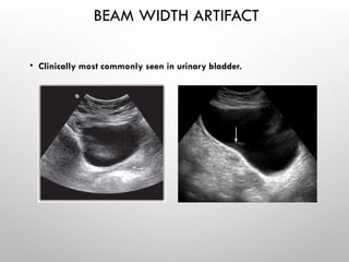
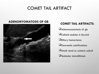
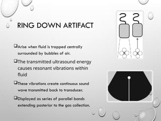
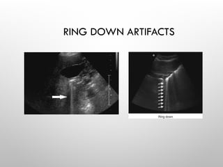
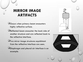
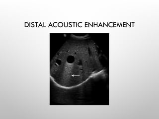
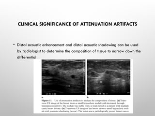
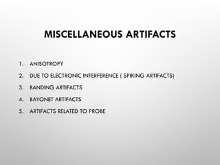
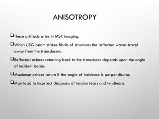
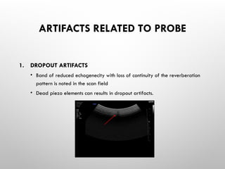
ARTIFACTS IN USG
ARTIFACTS
Any part of an image that doesn’t actually represent the anatomic
structures present within the subject being evaluated.
IN GENERAL ,USG ARTIFACTS MAY BE:
a. structures that appear in the display but anatomically not present.
b. structures that don’t appear in the display but anatomically present.
WHY DO ARTIFACTS ARISE?
WE MAKE FOLLOWING ASSUMPTIONS IN USG IMAGING:
a. Sound wave arise uniformly from the transducer.
b. Echoes return back after a single reflection.
c. Depth is simply the time taken for the round trip of the sound.
d. Speed of sound waves in human soft tissue is constant at 1540m/sec.
e. Echoes travel in straight path.
f. Acoustic energy of USG beam in uniformly attenuated.
ARTIFACTS ARISE FROM
INHERENT CHARACTERISTICS OF THE USG BEAM.
PRESENCE OF MULTIPLE ECHOES.
ERRORS IN VELOCITY.
ERRORS IN ATTENUATION.
1.ARTIFACTS ASSOCIATED WITH
ULTRASOUND BEAM CHARACTERISTICS
Two artifacts associated:
Beam width artifacts
Side lobe artifacts
• The ultrasound beam exits the transducer bowtie shape with additional off-
axis low-energy beams, which are referred to as side lobes and grating
lobes.
• A strong reflector located outside of the main ultrasound beam may
generate echoes that are detectable by the transducer.
• These echoes will be falsely displayed as having originated from within the
main beam.
BEAM WIDTH ARTIFACTS
 The main ultrasound beam exits the
transducer at approximately the same width
as the transducer, then narrows as it
approaches the focal zone and widens
again distal to the focal zone
 Artifacts occurs if structure lie in the
diverging width of the beam but out of the
line of the transducer.
 Artifact will be the display of that very
image combined with other image.
BEAM WIDTH ARTIFACT
• Clinically most commonly seen in urinary bladder.
• OVERCOME BY
• Adjusting focal length to level of
interest
• Placing the transducer at the center
of object of interest.
SIDE LOBE ARTIFACTS
 Are multiple beams of low-amplitude ultrasound energy that project radially
from the main beam axis.
 Produced by radial expansion of piezoelectric crystals.
 Mainly seen in linear array transducer
SIDE LOBE ARTIFACTS
• When a strong reflectors present in the
path of these low-energy, off-axis beams
may create echoes detectable by the
transducer.
• These echoes will be displayed as having
originated from within the main beam in the
side lobe artifact
SIDE LOBE ARTIFACT
2.Artifacts associated with multiple
echoes
System assumes echoes return after single reflection and the depth of
the structures imaged is the time taken for round travel.
TYPES:
a. Reverberation artifact
 Comet tail artifact
 Ring down artifact
b. Mirror image artifact
 In the presence of two parallel highly reflective
surfaces, the echoes generated from a primary
beam may be repeatedly reflected back and
forth before returning to the transducer.
 When this occurs, multiple echoes are recorded
and displayed.
 The echo that returns to the transducer after a
single reflection will be displayed in the proper
location.
 The sequential echoes will take longer to return
to the transducer, and the ultrasound processor
will place the delayed echoes at equidistance
Reverberation artifacts
REVERBERATION ARTIFACT
• MAINLY TWO TYPES
 Comet tail artifact
 Ring down artifact
Two reflective surfaces are very close.
Echoes from these surfaces are very
near and it is difficult for the system to
perceive individual signals.
Echoes that arrive late have reduced
amplitude.
Triangular tapered image is created
and displayed.
COMET TAIL ARTIFACT
COMET TAIL ARTIFACT
ADENOMYOMATOSIS OF GB
COMET TAIL ARTIFACTS:
Adenomyomatosis of gb
Colloid nodules in thyroid
Biliary hamartoma
Pancreatic calcifications
Small renal or ureteric calculi
Testicular microlithiasis
RING DOWN ARTIFACT
Arise when fluid is trapped centrally
surrounded by bubbles of air.
The transmitted ultrasound energy
causes resonant vibrations within
fluid
These vibrations create continuous sound
wave transmitted back to transducer.
Displayed as series of parallel bands
extending posterior to the gas collection.
RING DOWN ARTIFACTS
Occurs when primary beam encounters
highly reflective surface.
Reflected beam encounter the back side of
another structure and are reflected back to
the reflective interface.
Two mirror image structures equidistant
from the reflective interface are seen.
Diaphragm and pleural air interface is an
example.
MIRROR IMAGE
ARTIFACTS
MIRROR IMAGE ARTIFACTS
3.Artifacts associated with velocity
errors
Arise because velocity of sound wave differs in various parts of the body.
The average velocity in human body of the sound waves considered as
1540m/s.
Deviation from this causes these artifacts.
 Types:
a. speed displacement artifact.
b. refraction artifact.
SPEED DISPLACEMENT
ARTIFACT
Arise when the sound wave encounters two
medium with different velocities for the
wave.
If the encountered structure has lesser
velocity that the surrounding than the
resultant display of the structure of interest
will be farther than its actual anatomical
position.
SPEED DISPLACEMENT ARTIFACT
REFRACTION ARTIFACT
Arise when sound travels in medium with two different velocities and
sound wave changes its original course.
Refraction isn't read by the system and the images are displayed in a
single line.
Occur in pelvic structures deep to the rectus muscles and fat.
Structure may be wide and duplicated.
REFRACTION ARTIFACT
GHOSTING ARTIFACTS
Seen due to refraction
• Centrally, no refraction occurs and the true position
(black circle) of the object is obtained.
• Transverse US image of the liver shows ghosting artifact of the
aorta, which appears in duplicate (arrows) deep to the rectus abdominis musculature
EDGE SHADOWING
Diagram shows edge shadowing (defocusing) at the edge of a cystic structure with a different
speed of sound than that of the surrounding medium. Refraction is greatest at the edges,
resulting in shadowing due to the decreased beam intensity to deeper tissue
4.Artifacts associated with attenuation
errors
 Different structures attenuate sound beam differently.
 When the ultra- sound beam encounters a strongly attenuating or highly reflective
structure, the amplitude of the beam distal to this structure is diminished
 The echoes returning from structures beyond the highly attenuating structure will
also be diminished.
 In clinical imaging, this phenomenon is recognized as a dark or hypoechoic band.
 TYPES:
a. DISTAL ACOUSTIC SHADOWING
b. DISTAL ACOUSTIC ENHANCEMENT OR INCREASED THROUGH TRANSMISSION
When an us beam encounter focal material
that attenuates sound greater than the
surrounding tissue, strength of the beam distal
to this structure will be weak.
Arise from solid structures like bone, stone.
Also arise form air with dirty distal shadow.
DISTAL ACOUSTIC
SHADOWING
DISTAL ACOUSTIC SHADOWING
When an us beam encounter focal
material that attenuates sound lesser
than the surrounding tissue, strength of
the beam distal to this structure will be
strong.
Arise from cystic structures.
DISTAL ACOUSTIC
ENHANCEMENT
DISTAL ACOUSTIC ENHANCEMENT
CLINICAL SIGNIFICANCE OF ATTENUATION ARTIFACTS
• Distal acoustic enhancement and distal acoustic shadowing can be used
by radiologist to determine the composition of tissue to narrow down the
differential
MISCELLANEOUS ARTIFACTS
1. ANISOTROPY
2. DUE TO ELECTRONIC INTERFERENCE ( SPIKING ARTIFACTS)
3. BANDING ARTIFACTS
4. BAYONET ARTIFACTS
5. ARTIFACTS RELATED TO PROBE
ANISOTROPY
These artifacts arise in MSK imaging.
When USG beam strikes fibrils of structures the reflected waves travel
away from the transducers.
Reflected echoes returning back to the transducer depends upon the angle
of incident beam.
Maximum echoes return if the angle of incidence is perpendicular.
May lead to incorrect diagnosis of tendon tears and tendinosis.
ANISOTROPY
SPIKING ARTIFACTS
• If non-dedicated electrical outlet is used along with another piece of
equipment turned on , spurious electronic signals are detected by the US
system bands of noise are displayed.
BANDING ARTIFACTS
• Band of increased brightness is seen at the focal zone.
• Improper focal zone setting or time gain compensation settings can
create banding artifact
• Appearance:-
BAND OF INCREASED BRIGHTNESS.
BAYONET ARTIFACTS
• Seen in ultrasound guided needle techniques
• Results in apparent bending of needle as it passes into tissue with
different sound transmission speed.
ARTIFACTS RELATED TO PROBE
1. DROPOUT ARTIFACTS
• Band of reduced echogenecity with loss of continuity of the reverberation
pattern is noted in the scan field
• Dead piezo elements can results in dropout artifacts.
2. DELAMINATION
• Disrupted reverberation pattern without complete signal loss
• Due to weak piezo-element or manufacturing defect
CONCLUSION
Artifacts are commonly encountered in usg.
Often they are unavoidable.when done with proper technique, some
artifacts can be minimized.
Ability to recognize potentially correctable artifacts
a. improve image quality.
b. optimal patient care.
Artifacts may give clue to tissue composition
REFERENCE
• Diagnostic ultrasound, rumac & levine 5th
editions.
• US artifacts, volume 29 ,number 4, 2009 , RSNA
THANK YOU

USG Artifacts.........................................

  • 1.
  • 2.
    ARTIFACTS Any part ofan image that doesn’t actually represent the anatomic structures present within the subject being evaluated. IN GENERAL ,USG ARTIFACTS MAY BE: a. structures that appear in the display but anatomically not present. b. structures that don’t appear in the display but anatomically present.
  • 3.
    WHY DO ARTIFACTSARISE? WE MAKE FOLLOWING ASSUMPTIONS IN USG IMAGING: a. Sound wave arise uniformly from the transducer. b. Echoes return back after a single reflection. c. Depth is simply the time taken for the round trip of the sound. d. Speed of sound waves in human soft tissue is constant at 1540m/sec. e. Echoes travel in straight path. f. Acoustic energy of USG beam in uniformly attenuated.
  • 4.
    ARTIFACTS ARISE FROM INHERENTCHARACTERISTICS OF THE USG BEAM. PRESENCE OF MULTIPLE ECHOES. ERRORS IN VELOCITY. ERRORS IN ATTENUATION.
  • 5.
    1.ARTIFACTS ASSOCIATED WITH ULTRASOUNDBEAM CHARACTERISTICS Two artifacts associated: Beam width artifacts Side lobe artifacts • The ultrasound beam exits the transducer bowtie shape with additional off- axis low-energy beams, which are referred to as side lobes and grating lobes. • A strong reflector located outside of the main ultrasound beam may generate echoes that are detectable by the transducer. • These echoes will be falsely displayed as having originated from within the main beam.
  • 6.
    BEAM WIDTH ARTIFACTS The main ultrasound beam exits the transducer at approximately the same width as the transducer, then narrows as it approaches the focal zone and widens again distal to the focal zone  Artifacts occurs if structure lie in the diverging width of the beam but out of the line of the transducer.  Artifact will be the display of that very image combined with other image.
  • 7.
    BEAM WIDTH ARTIFACT •Clinically most commonly seen in urinary bladder.
  • 8.
    • OVERCOME BY •Adjusting focal length to level of interest • Placing the transducer at the center of object of interest.
  • 9.
    SIDE LOBE ARTIFACTS Are multiple beams of low-amplitude ultrasound energy that project radially from the main beam axis.  Produced by radial expansion of piezoelectric crystals.  Mainly seen in linear array transducer
  • 10.
    SIDE LOBE ARTIFACTS •When a strong reflectors present in the path of these low-energy, off-axis beams may create echoes detectable by the transducer. • These echoes will be displayed as having originated from within the main beam in the side lobe artifact
  • 11.
  • 12.
    2.Artifacts associated withmultiple echoes System assumes echoes return after single reflection and the depth of the structures imaged is the time taken for round travel. TYPES: a. Reverberation artifact  Comet tail artifact  Ring down artifact b. Mirror image artifact
  • 13.
     In thepresence of two parallel highly reflective surfaces, the echoes generated from a primary beam may be repeatedly reflected back and forth before returning to the transducer.  When this occurs, multiple echoes are recorded and displayed.  The echo that returns to the transducer after a single reflection will be displayed in the proper location.  The sequential echoes will take longer to return to the transducer, and the ultrasound processor will place the delayed echoes at equidistance Reverberation artifacts
  • 14.
    REVERBERATION ARTIFACT • MAINLYTWO TYPES  Comet tail artifact  Ring down artifact
  • 15.
    Two reflective surfacesare very close. Echoes from these surfaces are very near and it is difficult for the system to perceive individual signals. Echoes that arrive late have reduced amplitude. Triangular tapered image is created and displayed. COMET TAIL ARTIFACT
  • 16.
    COMET TAIL ARTIFACT ADENOMYOMATOSISOF GB COMET TAIL ARTIFACTS: Adenomyomatosis of gb Colloid nodules in thyroid Biliary hamartoma Pancreatic calcifications Small renal or ureteric calculi Testicular microlithiasis
  • 17.
    RING DOWN ARTIFACT Arisewhen fluid is trapped centrally surrounded by bubbles of air. The transmitted ultrasound energy causes resonant vibrations within fluid These vibrations create continuous sound wave transmitted back to transducer. Displayed as series of parallel bands extending posterior to the gas collection.
  • 18.
  • 19.
    Occurs when primarybeam encounters highly reflective surface. Reflected beam encounter the back side of another structure and are reflected back to the reflective interface. Two mirror image structures equidistant from the reflective interface are seen. Diaphragm and pleural air interface is an example. MIRROR IMAGE ARTIFACTS
  • 20.
  • 21.
    3.Artifacts associated withvelocity errors Arise because velocity of sound wave differs in various parts of the body. The average velocity in human body of the sound waves considered as 1540m/s. Deviation from this causes these artifacts.  Types: a. speed displacement artifact. b. refraction artifact.
  • 22.
    SPEED DISPLACEMENT ARTIFACT Arise whenthe sound wave encounters two medium with different velocities for the wave. If the encountered structure has lesser velocity that the surrounding than the resultant display of the structure of interest will be farther than its actual anatomical position.
  • 23.
  • 24.
    REFRACTION ARTIFACT Arise whensound travels in medium with two different velocities and sound wave changes its original course. Refraction isn't read by the system and the images are displayed in a single line. Occur in pelvic structures deep to the rectus muscles and fat. Structure may be wide and duplicated.
  • 25.
  • 26.
    GHOSTING ARTIFACTS Seen dueto refraction • Centrally, no refraction occurs and the true position (black circle) of the object is obtained. • Transverse US image of the liver shows ghosting artifact of the aorta, which appears in duplicate (arrows) deep to the rectus abdominis musculature
  • 27.
    EDGE SHADOWING Diagram showsedge shadowing (defocusing) at the edge of a cystic structure with a different speed of sound than that of the surrounding medium. Refraction is greatest at the edges, resulting in shadowing due to the decreased beam intensity to deeper tissue
  • 28.
    4.Artifacts associated withattenuation errors  Different structures attenuate sound beam differently.  When the ultra- sound beam encounters a strongly attenuating or highly reflective structure, the amplitude of the beam distal to this structure is diminished  The echoes returning from structures beyond the highly attenuating structure will also be diminished.  In clinical imaging, this phenomenon is recognized as a dark or hypoechoic band.  TYPES: a. DISTAL ACOUSTIC SHADOWING b. DISTAL ACOUSTIC ENHANCEMENT OR INCREASED THROUGH TRANSMISSION
  • 29.
    When an usbeam encounter focal material that attenuates sound greater than the surrounding tissue, strength of the beam distal to this structure will be weak. Arise from solid structures like bone, stone. Also arise form air with dirty distal shadow. DISTAL ACOUSTIC SHADOWING
  • 30.
  • 31.
    When an usbeam encounter focal material that attenuates sound lesser than the surrounding tissue, strength of the beam distal to this structure will be strong. Arise from cystic structures. DISTAL ACOUSTIC ENHANCEMENT
  • 32.
  • 33.
    CLINICAL SIGNIFICANCE OFATTENUATION ARTIFACTS • Distal acoustic enhancement and distal acoustic shadowing can be used by radiologist to determine the composition of tissue to narrow down the differential
  • 34.
    MISCELLANEOUS ARTIFACTS 1. ANISOTROPY 2.DUE TO ELECTRONIC INTERFERENCE ( SPIKING ARTIFACTS) 3. BANDING ARTIFACTS 4. BAYONET ARTIFACTS 5. ARTIFACTS RELATED TO PROBE
  • 35.
    ANISOTROPY These artifacts arisein MSK imaging. When USG beam strikes fibrils of structures the reflected waves travel away from the transducers. Reflected echoes returning back to the transducer depends upon the angle of incident beam. Maximum echoes return if the angle of incidence is perpendicular. May lead to incorrect diagnosis of tendon tears and tendinosis.
  • 36.
  • 37.
    SPIKING ARTIFACTS • Ifnon-dedicated electrical outlet is used along with another piece of equipment turned on , spurious electronic signals are detected by the US system bands of noise are displayed.
  • 38.
    BANDING ARTIFACTS • Bandof increased brightness is seen at the focal zone. • Improper focal zone setting or time gain compensation settings can create banding artifact • Appearance:- BAND OF INCREASED BRIGHTNESS.
  • 39.
    BAYONET ARTIFACTS • Seenin ultrasound guided needle techniques • Results in apparent bending of needle as it passes into tissue with different sound transmission speed.
  • 40.
    ARTIFACTS RELATED TOPROBE 1. DROPOUT ARTIFACTS • Band of reduced echogenecity with loss of continuity of the reverberation pattern is noted in the scan field • Dead piezo elements can results in dropout artifacts.
  • 41.
    2. DELAMINATION • Disruptedreverberation pattern without complete signal loss • Due to weak piezo-element or manufacturing defect
  • 42.
    CONCLUSION Artifacts are commonlyencountered in usg. Often they are unavoidable.when done with proper technique, some artifacts can be minimized. Ability to recognize potentially correctable artifacts a. improve image quality. b. optimal patient care. Artifacts may give clue to tissue composition
  • 43.
    REFERENCE • Diagnostic ultrasound,rumac & levine 5th editions. • US artifacts, volume 29 ,number 4, 2009 , RSNA
  • 44.

Editor's Notes

  • #19 Also seen in transcranial USG – Reflective surfaces being cranial vault and the transducer itself.