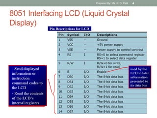
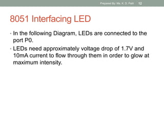
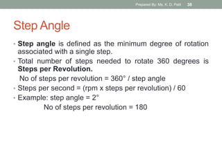
This document provides an overview of interfacing various devices with the 8051 microcontroller, including LCDs, LEDs, 7-segment displays, ADCs, DACs, temperature sensors, stepper motors, keyboards, and more. It includes diagrams of pin connections and code examples. The document was prepared by Ms. K. D. Patil and covers topics related to processor architecture and interfacing for a class.
Overview of Crystal Oscillator Circuit Working and Its Applicationelprocus
A crystal oscillator is an electronic oscillator circuit which is used for the mechanical resonance of a vibrating crystal of piezoelectric material. It will create an electrical signal with a given frequency. This frequency is commonly used to keep track of time.
This presentation is all about interfacing of a character LCD with 8051 micro-controller. It discusses various LCD commands, LCD pin description and a simple LCD working code in assembly for interfacing.
Optimum Receiver corrupted by AWGN ChannelAWANISHKUMAR84
Optimum Receiver corrupted by AWGN Channel
This topic is related to Advance Digital Communication Engineering. In this ppt, you will get all details explanations of the receiver how to get affected by white Noise.
A seven-segment display is a form of electronic display device for displaying decimal numerals that is an alternative to the more complex dot matrix displays. Seven-segment displays are widely used in digital clocks, electronic meters, basic calculators, and other electronic devices that display numerical information.
A Bioamplifier is an electrophysiological device, a variation of the instrumentation amplifier, used to gather and increase the signal integrity of physiologic electrical activity for output to various sources. It may be an independent unit, or integrated into the electrodes.
A Kelvin bridge, also called a Kelvin double bridge and in some countries a Thomson bridge, is a measuring instrument used to measure unknown electrical resistors below 1 ohm. It is specifically designed to measure resistors that are constructed as four terminal resistors.
An analog-to-digital converter (ADC, A/D, or A to D) is a device that converts a continuous physical quantity (usually voltage) to a digital number that represents the quantity's amplitude.
The conversion involves quantization of the input, so it necessarily introduces a small amount of error. Instead of doing a single conversion, an ADC often performs the conversions ("samples" the input) periodically. The result is a sequence of digital values that have been converted from a continuous-time and continuous-amplitude analog signal to a discrete-time and discrete-amplitude digital signal.
Digital voltmeter using 89c51 microcontrollerSaylee joshi
Voltmeter is a voltage measuring instrument.
We can measure the potential difference between any two points in an electrical network using voltmeter.
There are two types of voltmeter as analog voltmeter and digital voltmeter.
Analog voltmeter moves pointer on a scale but it has some limitations like accuracy of few percent of full scale.
Digital voltmeter can display numerical value of voltage on a display by use of analog to digital converter (ADC).
All the data processing and manipulating is in digital form, so it is very essential to use ADC.
We have used ADC0804 analog-to-digital converter IC. The range of input voltage is 0-15V. Here the input voltage should be DC voltage so as to get the steady output on the LCD display.
If you give the AC voltage as an input, it will display continuously running numbers as the nature of AC voltage.
final Year Projects, Final Year Projects in Chennai, Software Projects, Embedded Projects, Microcontrollers Projects, DSP Projects, VLSI Projects, Matlab Projects, Java Projects, .NET Projects, IEEE Projects, IEEE 2009 Projects, IEEE 2009 Projects, Software, IEEE 2009 Projects, Embedded, Software IEEE 2009 Projects, Embedded IEEE 2009 Projects, Final Year Project Titles, Final Year Project Reports, Final Year Project Review, Robotics Projects, Mechanical Projects, Electrical Projects, Power Electronics Projects, Power System Projects, Model Projects, Java Projects, J2EE Projects, Engineering Projects, Student Projects, Engineering College Projects, MCA Projects, BE Projects, BTech Projects, ME Projects, MTech Projects, Wireless Networks Projects, Network Security Projects, Networking Projects, final year projects, ieee projects, student projects, college projects, ieee projects in chennai, java projects, software ieee projects, embedded ieee projects, "ieee2009projects", "final year projects", "ieee projects", "Engineering Projects", "Final Year Projects in Chennai", "Final year Projects at Chennai", Java Projects, ASP.NET Projects, VB.NET Projects, C# Projects, Visual C++ Projects, Matlab Projects, NS2 Projects, C Projects, Microcontroller Projects, ATMEL Projects, PIC Projects, ARM Projects, DSP Projects, VLSI Projects, FPGA Projects, CPLD Projects, Power Electronics Projects, Electrical Projects, Robotics Projects, Solor Projects, MEMS Projects, J2EE Projects, J2ME Projects, AJAX Projects, Structs Projects, EJB Projects, Real Time Projects, Live Projects, Student Projects, Engineering Projects, MCA Projects, MBA Projects, College Projects, BE Projects, BTech Projects, ME Projects, MTech Projects, M.Sc Projects, Final Year Java Projects, Final Year ASP.NET Projects, Final Year VB.NET Projects, Final Year C# Projects, Final Year Visual C++ Projects, Final Year Matlab Projects, Final Year NS2 Projects, Final Year C Projects, Final Year Microcontroller Projects, Final Year ATMEL Projects, Final Year PIC Projects, Final Year ARM Projects, Final Year DSP Projects, Final Year VLSI Projects, Final Year FPGA Projects, Final Year CPLD Projects, Final Year Power Electronics Projects, Final Year Electrical Projects, Final Year Robotics Projects, Final Year Solor Projects, Final Year MEMS Projects, Final Year J2EE Projects, Final Year J2ME Projects, Final Year AJAX Projects, Final Year Structs Projects, Final Year EJB Projects, Final Year Real Time Projects, Final Year Live Projects, Final Year Student Projects, Final Year Engineering Projects, Final Year MCA Projects, Final Year MBA Projects, Final Year College Projects, Final Year BE Projects, Final Year BTech Projects, Final Year ME Projects, Final Year MTech Projects, Final Year M.Sc Projects, IEEE Java Projects, ASP.NET Projects, VB.NET Projects, C# Projects, Visual C++ Projects, Matlab Projects, NS2 Projects, C Projects, Microcontroller Projects, ATMEL Projects, PIC Projects, ARM Projects, DSP Projects, VLSI Projects, FPGA Projects, CPLD Projects, Power Electronics Projects, Electrical Projects, Robotics Projects, Solor Projects, MEMS Projects, J2EE Projects, J2ME Projects, AJAX Projects, Structs Projects, EJB Projects, Real Time Projects, Live Projects, Student Projects, Engineering Projects, MCA Projects, MBA Projects, College Projects, BE Projects, BTech Projects, ME Projects, MTech Projects, M.Sc Projects, IEEE 2009 Java Projects, IEEE 2009 ASP.NET Projects, IEEE 2009 VB.NET Projects, IEEE 2009 C# Projects, IEEE 2009 Visual C++ Projects, IEEE 2009 Matlab Projects, IEEE 2009 NS2 Projects, IEEE 2009 C Projects, IEEE 2009 Microcontroller Projects, IEEE 2009 ATMEL Projects, IEEE 2009 PIC Projects, IEEE 2009 ARM Projects, IEEE 2009 DSP Projects, IEEE 2009 VLSI Projects, IEEE 2009 FPGA Projects, IEEE 2009 CPLD Projects, IEEE 2009 Power Electronics Projects, IEEE 2009 Electrical Projects, IEEE 2009 Robotics Projects, IEEE 2009 Solor Projects, IEEE 2009 MEMS Projects, IEEE 2009 J2EE P
Temperature Based Fan Controller can be used for reducing the power consumption & also to assist people who are disabled and are unable to control the speed of fan.It may also be used for monitoring changes in environment.
The conventional lighting sources like incandescent and fluorescent lamps are replaced by High Brightness Light Emitting Diodes (HB-LEDs). In this paper, a HBLED driver using a Single Ended Primary Inductor Converter (SEPIC) with input Power Factor Correction (PFC) is presented. PFC is accomplished using a commercial inexpensive Peak Current Mode Controller (PCMC) IC UC3842 is newly combined with SEPIC converter. Extensive simulation results are carried out and a laboratory prototype to power 18W LED array from AC mains is implemented and the results are presented in detail.
Saudi Arabia stands as a titan in the global energy landscape, renowned for its abundant oil and gas resources. It's the largest exporter of petroleum and holds some of the world's most significant reserves. Let's delve into the top 10 oil and gas projects shaping Saudi Arabia's energy future in 2024.
Hierarchical Digital Twin of a Naval Power SystemKerry Sado
A hierarchical digital twin of a Naval DC power system has been developed and experimentally verified. Similar to other state-of-the-art digital twins, this technology creates a digital replica of the physical system executed in real-time or faster, which can modify hardware controls. However, its advantage stems from distributing computational efforts by utilizing a hierarchical structure composed of lower-level digital twin blocks and a higher-level system digital twin. Each digital twin block is associated with a physical subsystem of the hardware and communicates with a singular system digital twin, which creates a system-level response. By extracting information from each level of the hierarchy, power system controls of the hardware were reconfigured autonomously. This hierarchical digital twin development offers several advantages over other digital twins, particularly in the field of naval power systems. The hierarchical structure allows for greater computational efficiency and scalability while the ability to autonomously reconfigure hardware controls offers increased flexibility and responsiveness. The hierarchical decomposition and models utilized were well aligned with the physical twin, as indicated by the maximum deviations between the developed digital twin hierarchy and the hardware.
Welcome to WIPAC Monthly the magazine brought to you by the LinkedIn Group Water Industry Process Automation & Control.
In this month's edition, along with this month's industry news to celebrate the 13 years since the group was created we have articles including
A case study of the used of Advanced Process Control at the Wastewater Treatment works at Lleida in Spain
A look back on an article on smart wastewater networks in order to see how the industry has measured up in the interim around the adoption of Digital Transformation in the Water Industry.
NO1 Uk best vashikaran specialist in delhi vashikaran baba near me online vas...Amil Baba Dawood bangali
Contact with Dawood Bhai Just call on +92322-6382012 and we'll help you. We'll solve all your problems within 12 to 24 hours and with 101% guarantee and with astrology systematic. If you want to take any personal or professional advice then also you can call us on +92322-6382012 , ONLINE LOVE PROBLEM & Other all types of Daily Life Problem's.Then CALL or WHATSAPP us on +92322-6382012 and Get all these problems solutions here by Amil Baba DAWOOD BANGALI
#vashikaranspecialist #astrologer #palmistry #amliyaat #taweez #manpasandshadi #horoscope #spiritual #lovelife #lovespell #marriagespell#aamilbabainpakistan #amilbabainkarachi #powerfullblackmagicspell #kalajadumantarspecialist #realamilbaba #AmilbabainPakistan #astrologerincanada #astrologerindubai #lovespellsmaster #kalajaduspecialist #lovespellsthatwork #aamilbabainlahore#blackmagicformarriage #aamilbaba #kalajadu #kalailam #taweez #wazifaexpert #jadumantar #vashikaranspecialist #astrologer #palmistry #amliyaat #taweez #manpasandshadi #horoscope #spiritual #lovelife #lovespell #marriagespell#aamilbabainpakistan #amilbabainkarachi #powerfullblackmagicspell #kalajadumantarspecialist #realamilbaba #AmilbabainPakistan #astrologerincanada #astrologerindubai #lovespellsmaster #kalajaduspecialist #lovespellsthatwork #aamilbabainlahore #blackmagicforlove #blackmagicformarriage #aamilbaba #kalajadu #kalailam #taweez #wazifaexpert #jadumantar #vashikaranspecialist #astrologer #palmistry #amliyaat #taweez #manpasandshadi #horoscope #spiritual #lovelife #lovespell #marriagespell#aamilbabainpakistan #amilbabainkarachi #powerfullblackmagicspell #kalajadumantarspecialist #realamilbaba #AmilbabainPakistan #astrologerincanada #astrologerindubai #lovespellsmaster #kalajaduspecialist #lovespellsthatwork #aamilbabainlahore #Amilbabainuk #amilbabainspain #amilbabaindubai #Amilbabainnorway #amilbabainkrachi #amilbabainlahore #amilbabaingujranwalan #amilbabainislamabad
About
Indigenized remote control interface card suitable for MAFI system CCR equipment. Compatible for IDM8000 CCR. Backplane mounted serial and TCP/Ethernet communication module for CCR remote access. IDM 8000 CCR remote control on serial and TCP protocol.
• Remote control: Parallel or serial interface.
• Compatible with MAFI CCR system.
• Compatible with IDM8000 CCR.
• Compatible with Backplane mount serial communication.
• Compatible with commercial and Defence aviation CCR system.
• Remote control system for accessing CCR and allied system over serial or TCP.
• Indigenized local Support/presence in India.
• Easy in configuration using DIP switches.
Technical Specifications
Indigenized remote control interface card suitable for MAFI system CCR equipment. Compatible for IDM8000 CCR. Backplane mounted serial and TCP/Ethernet communication module for CCR remote access. IDM 8000 CCR remote control on serial and TCP protocol.
Key Features
Indigenized remote control interface card suitable for MAFI system CCR equipment. Compatible for IDM8000 CCR. Backplane mounted serial and TCP/Ethernet communication module for CCR remote access. IDM 8000 CCR remote control on serial and TCP protocol.
• Remote control: Parallel or serial interface
• Compatible with MAFI CCR system
• Copatiable with IDM8000 CCR
• Compatible with Backplane mount serial communication.
• Compatible with commercial and Defence aviation CCR system.
• Remote control system for accessing CCR and allied system over serial or TCP.
• Indigenized local Support/presence in India.
Application
• Remote control: Parallel or serial interface.
• Compatible with MAFI CCR system.
• Compatible with IDM8000 CCR.
• Compatible with Backplane mount serial communication.
• Compatible with commercial and Defence aviation CCR system.
• Remote control system for accessing CCR and allied system over serial or TCP.
• Indigenized local Support/presence in India.
• Easy in configuration using DIP switches.
1. 8051 Interfacing & Applications
Subject : Processor Architecture & Interfacing
Class : SEIT
Prepared By
Ms. K. D. Patil, AP
Department of IT, Sanjivani COE, Kopargaon.
Prepared By: Ms. K. D. Patil 1
9. LCD Program
• comm: ;SEND COMMAND TO LCD
• mov p0,a ;COPY REG A TO PORT0
• clr p2.2 ;RS=0 FOR COMMAND
• clr p2.1 ;R/W=0 FOR WRITE
• setb p2.0 ;E=1
• clr p2.0 ;E=0
ret
• data1: ;WRITE DATA TO LCD
• mov p0,a ;COPY REG A TO PORT0
• setb p2.2 ;RS=1 FOR DATA
• clr p2.1 ;R/W=0 FOR WRITE
• setb p2.0 ;E=1
• clr p2.0 ;E=0
ret
• delay: mov r1,#255
• here2: mov r2,#255
• here: djnz r2,here
• djnz r1,here2
• Ret
• end
Prepared By: Ms. K. D. Patil 9
10. 8051 Interfacing LED
• LED (Light Emitting Diode) is a P N
junction diode which emits light when
activated.
• It is activated when the PN junction
sustains a forward voltage (forward bias), a
current from P to N, called forward current.
• When this current is applied, electrons
recombine with electron holes within the
device thereby releasing energy in form of
light.
• LED finds application in traffic signals,
lighting, camera flashes etc.
• The way to distinguish between the
positive and negative terminal is, the
positive is longer than the negative in
length.
Prepared By: Ms. K. D. Patil 10
11. 8051 Interfacing LED
• While LEDs are interfaced
with 8051, Quartz crystals or
ceramic resonator that
determines the operating
frequency of 8051
microcontroller is needed.
• The XTAL1 and XTAL2 can
be configured in two ways;
• external clock drive configuration
• internal clock drive configuration.
• Two capacitors C1 and C2
are connected to the quartz
crystal. It can be a quartz
crystal or ceramic resonator.
• The crystal oscillator frequency is
from 1.2MHz to 12MHz. The crystal
oscillator is used to generate clock
pulses that provide the means for
timing calculation.
• Crystal pins are connected to the
ground through capacitors of 33pf.
Prepared By: Ms. K. D. Patil 11
12. 8051 Interfacing LED
• In the following Diagram, LEDs are connected to the
port P0.
• LEDs need approximately voltage drop of 1.7V and
10mA current to flow through them in order to glow at
maximum intensity.
Prepared By: Ms. K. D. Patil 12
14. 8051 Interfacing 7 Segment Display
• 7 segment display is a 10 pin electronic component
with eight led’s embedded inside it to displays number
from 0 to 9 even we can display few characters like A,
B, C, H, E, e, F, etc. .
• It is available in two configurations:
• common cathode
• common anode
• In Common Anode to light up any given segment the
corresponding Cathode pin should be connected to
ground or reference ,which completes the circuit and
LED will be in forward bias.
• In Common Cathode to corresponding LED Anode pin
the circuit will be completed and the particular LED will
be light up since it will be in forward bias.
Prepared By: Ms. K. D. Patil 14
15. 8051 Interfacing 7 Segment Display
• A seven segment display consists
of seven LEDs arranged in the
form of a “squarish eight”
slightly inclined to the right and a
single LED as the dot character.
Different characters can be
displayed by selectively glowing
the required LED segments.
Prepared By: Ms. K. D. Patil 15
17. 8051 Interfacing ADC
• Digital computers use binary
values but in physical world
everything is Analog
(continuous) eg. Temperature,
Pressure
• A physical quantity is converted
into electrical (voltage, current)
signals using a device called as
Transducer (also referred as
Sensors).
• We need Analog-to-Digital
converter (ADC) to translate
Analog signals to Digital number
so that Microcontroller can read
and process them.
• ADC0808 allows us to monitor
upto 8 different analog input
channels using single chip
Prepared By: Ms. K. D. Patil 17
19. Address Lines (A,B,C)
Selected ADC
channel
C B A
IN0 0 0 0
IN1 0 0 1
IN2 0 1 0
IN3 0 1 1
IN4 1 0 0
IN5 1 0 1
IN6 1 1 0
IN7 1 1 1
• ADC0808 has 8-bit
data output
• 8 analog input
channels are
multiplexed and
selected using three
address pins A, B & C.
Prepared By: Ms. K. D. Patil 19
20. Signals for A/D Conversion
• Address Latch Enable (ALE): A LOW-TO-HIGH signal at this
pin will latch the above-selected address and selected the
respective channel for ADC conversion.
• START Conversion (SC): The A/D converter‟s successive
approximation register (SAR) is reset on the positive edge of the
start conversion (SC) pulse. Thus we need to generate a LOW-
HIGH pulse for starting the ADC conversion.
• End of Conversion (EOC): Once the conversion is over, this
pin is pulled HIGH by ADC0808. This pin needs to be monitored
for the conversion to complete and then read the data.
• Output Enable(OE): ADC0808 does the A/D conversion and
holds the data in the internal registers. A HIGH signal on this pin
will bring the data on the output lines.
• D0-D7 are the digital Data output lines.
Prepared By: Ms. K. D. Patil 20
23. 8051 Interfacing Temperature Sensor
(LM34/LM35)
• Temperature is converted to electrical signals using a
transducer called as Thermistor.
• Simple and widely used Temperature sensors include
LM34 & LM35 from Semiconductor Corp
• LM34 does not require external calibration since it is
internally calibrated.
• LM35 are precision integrated circuit temperature sensors
whose output voltage is linearly proportional to Celsius
temp. It does not require external calibration since it is
internally calibrated. It outputs 10mV for each degree of
centigrade temperature.
Prepared By: Ms. K. D. Patil 23
24. Signal Conditioning
• Sensors produce the
output in the form of
voltage, current, charge,
resistance & capacitance.
• But, we need to convert
these signals to voltage in
order to send input to ADC.
• This conversion is called as
Signal conditioning.
• Signal conditioning can be
current to voltage
conversion or signal
amplification.
Analog World
(temperature, pressure)
Transducer (Sensor)
Signal Conditioning
ADC
Microcontroller
Prepared By: Ms. K. D. Patil 24
25. Connecting LM35 to ADC
Temp (C) Vin (mV) Vout
(D7-D0)
0 0 0000 0000
1 10 0000 0001
2 20 0000 0010
3 30 0000 0011
10 100 0000 1010
30 300 0001 1110
• Since ADC has 8 bit
resolution with a max
of 256 steps and LM35
produces 10mV for
every degree of
temperature change,
we can condition Vin of
the ADC to produce a
Vout of 2.56V for full
scale output. So
Vref= 2.56
Temperature Vs Vout for ADC
Prepared By: Ms. K. D. Patil 25
27. 8051 Interfacing DAC
• Microcontroller are used in wide variety of applications like for
measuring and control of physical quantity like temperature,
pressure, speed, distance, etc.
• In these systems microcontroller generates output which is in
digital form but the controlling system requires analog signal as
they don't accept digital data thus making it necessary to use
DAC which converts digital data into equivalent analog voltage
• Digital to Analog Converter is a device used to convert digital
pulses to analog signals.
• In the figure shown, we use 8-bit DAC 0808. This IC converts
digital data into equivalent analog Current. Hence we require an
I to V converter to convert this current into equivalent voltage.
• DAC0808 provides 256 discrete voltage (or current) levels of
output.
Prepared By: Ms. K. D. Patil 27
28. DAC0808
• In the MC1408 (DAC0808), the digital inputs are converted
to current (Iout), and by connecting a resistor to the Iout pin,
we convert the result to voltage.
• The total current provided by the Iout pin is a function of the
binary numbers at the D0 – D7 inputs of the DAC0808 and
the reference current (Iref), and is as follows:
• where D0 is the LSB, D7 is the MSB for the inputs, and Iref
is the input current that must be applied to pin 14. The Iref
current is generally set to 2.0 mA.
Prepared By: Ms. K. D. Patil 28
31. 8051 Interfacing Stepper Motor
Stepper motor is a widely
used device that
translates electrical pulses
into mechanical
movement
Stepper motor is used in
applications for position
control such as
disk drives
dot matrix printer
robotics etc.
Stepper motors commonly
have a permanent magnet
rotor (shaft) surrounded
by a stator
Prepared By: Ms. K. D. Patil 31
32. • Commonly used stepper
motors have four stator
windings that are paired
with a center – tapped
common. Such motors are
called as four-phase or
unipolar stepper motor.
• It has a permanent magnet
rotor (shaft) which is
surrounded by a stator.
• A practical PM stepper
motor will have 1.8 degrees
step angle and 50 tooth on
its rotor.
• There are 8 main poles on
the stator, each having 5
tooth in the pole face
Prepared By: Ms. K. D. Patil 32
37. 4 step Sequence
Step Windi
ng A
Windi
ng B
Windi
ng C
Windi
ng D
1 1 0 0 1
2 1 1 0 0
3 0 1 1 0
4 0 0 1 1
Prepared By: Ms. K. D. Patil 37
38. Step Angle
• Step angle is defined as the minimum degree of rotation
associated with a single step.
• Total number of steps needed to rotate 360 degrees is
Steps per Revolution.
No of steps per revolution = 360° / step angle
• Steps per second = (rpm x steps per revolution) / 60
• Example: step angle = 2°
No of steps per revolution = 180
Prepared By: Ms. K. D. Patil 38
40. 8051 Interfacing Keyboard
• Keyboards are organized in a matrix of rows and columns.
• The CPU processes both rows and columns through ports
• So, with two 8-bit ports, an 8X8 matrix of keys can be
connected to the controller.
• When a key is pressed, a row and a column make a
contact. Otherwise there is no connection
• In microcontroller, programs stored in EPROM scan the
keys continuously.
• In the following figure, 4 X 4 matrix connected to two ports.
rows are connected to output ports and columns are
connected to an input port.
Prepared By: Ms. K. D. Patil 40
42. Scanning & Identifying Key
• It is a function of microcontroller to scan the keyboard
continuously to detect and identify key pressed
• To detect Pressed key microcontroller grounds all rows by
providing 0 to output latch, then it reads the columns
• If the data read from columns is D3-D0 = 1111 , no key is pressed
and the process continues till key press is detected.
• If one of the column bits has a zero, means key press has
occurred.
• If D3-D0 = 1101 this means that key in the column D1 has been
pressed.
• After detecting a key press, microcontroller will go through the process
of identifying key.
Prepared By: Ms. K. D. Patil 42
43. Scanning & Identifying Key
• Starting with the top Row, the microcontroller grounds it by
providing a low to Row D0 only
• If reads a column if data read is all 1s, no key in that row is
activated and the process is moved to the next row.
• It grounds the next row, reads the columns, and checks for
any zero
• This process continues until row is identified
• After identification of the Row in which Key has been
pressed, find out column the key press belongs to
Prepared By: Ms. K. D. Patil 43
44. References:
• M. A. Mazidi, J. C. Mazidi, R. D. McKinlay, “The 8051
Microcontroller & Embedded Systems using Assembly and
C”, 2nd Edition, Pearson publication
Prepared By: Ms. K. D. Patil 44