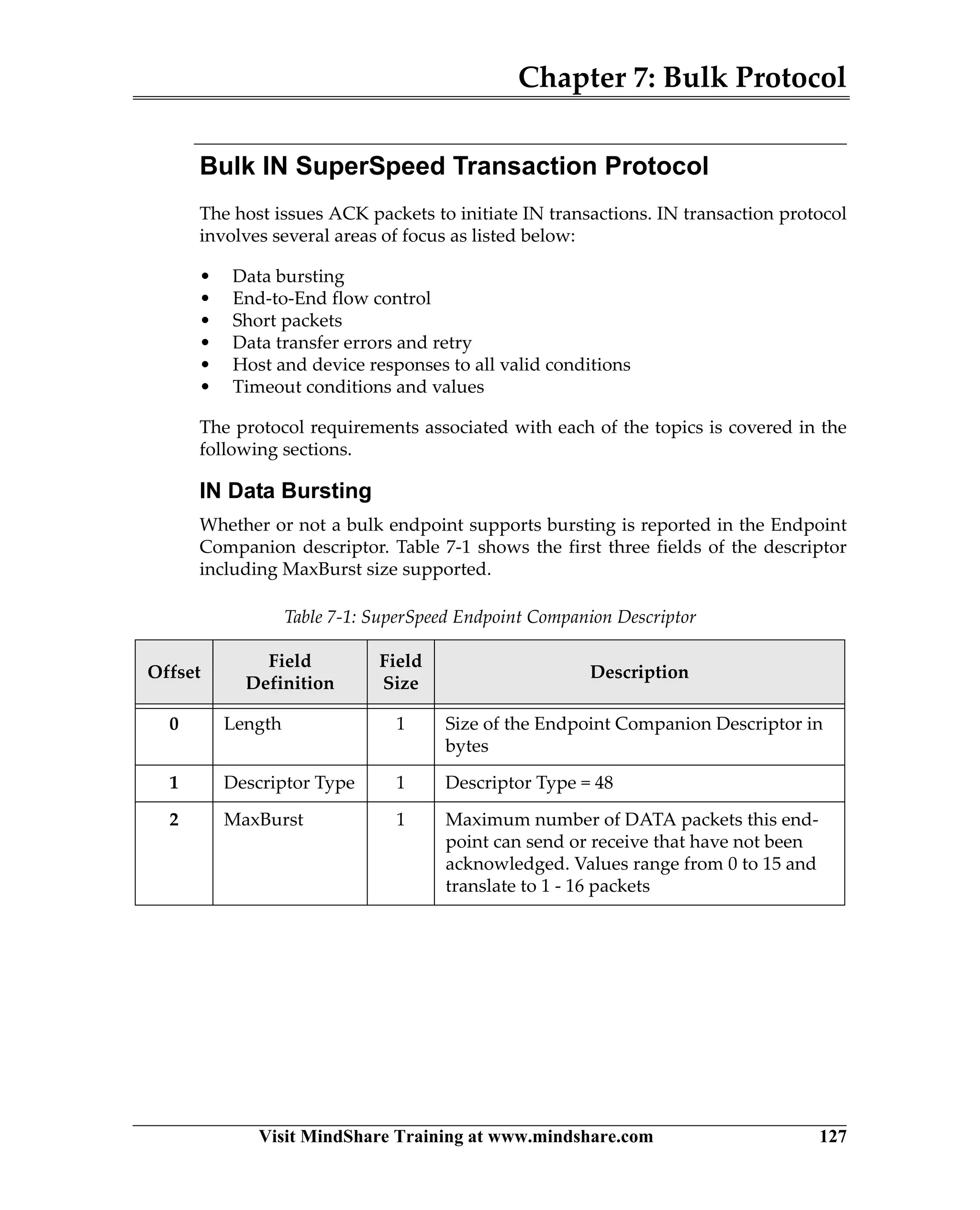
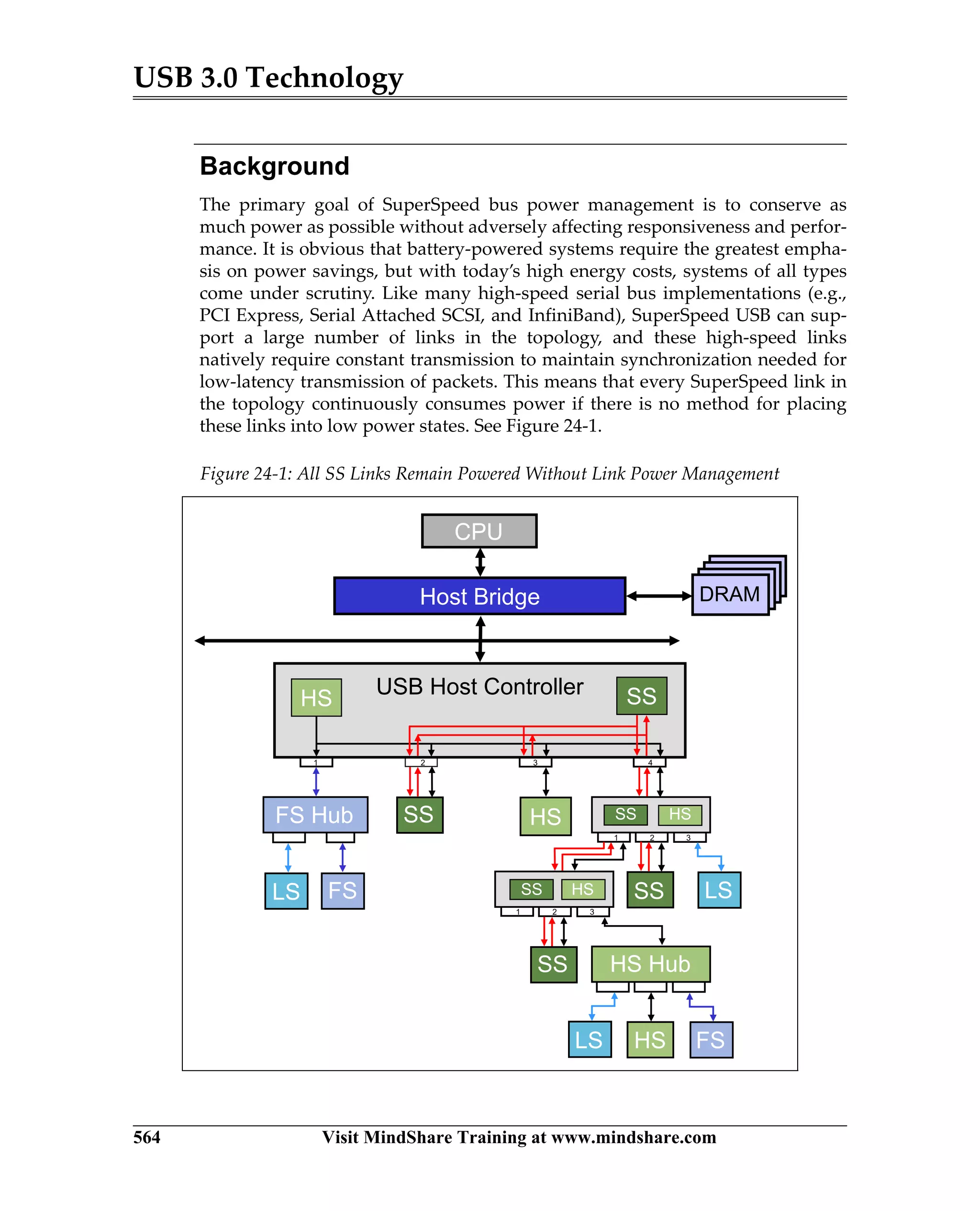
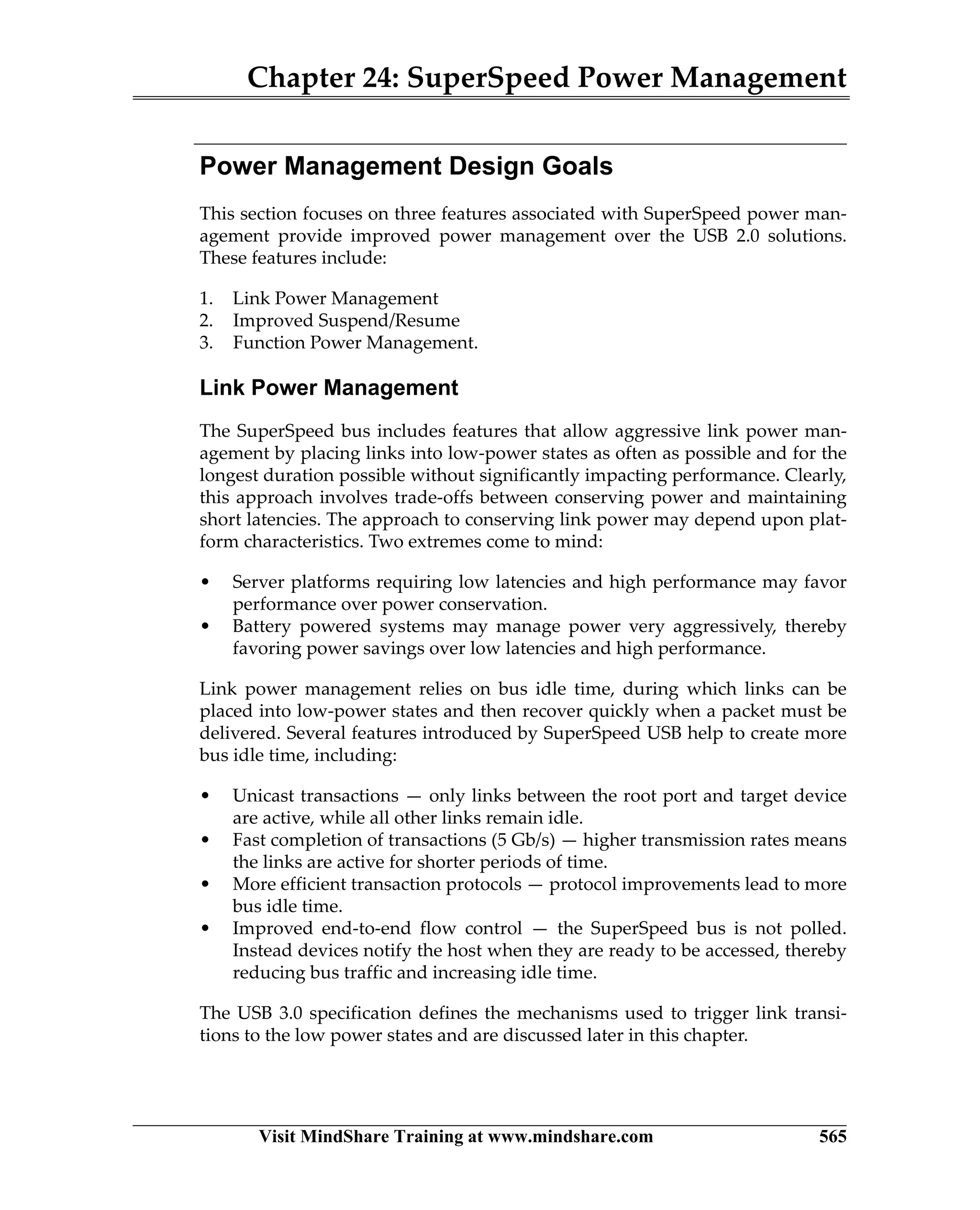
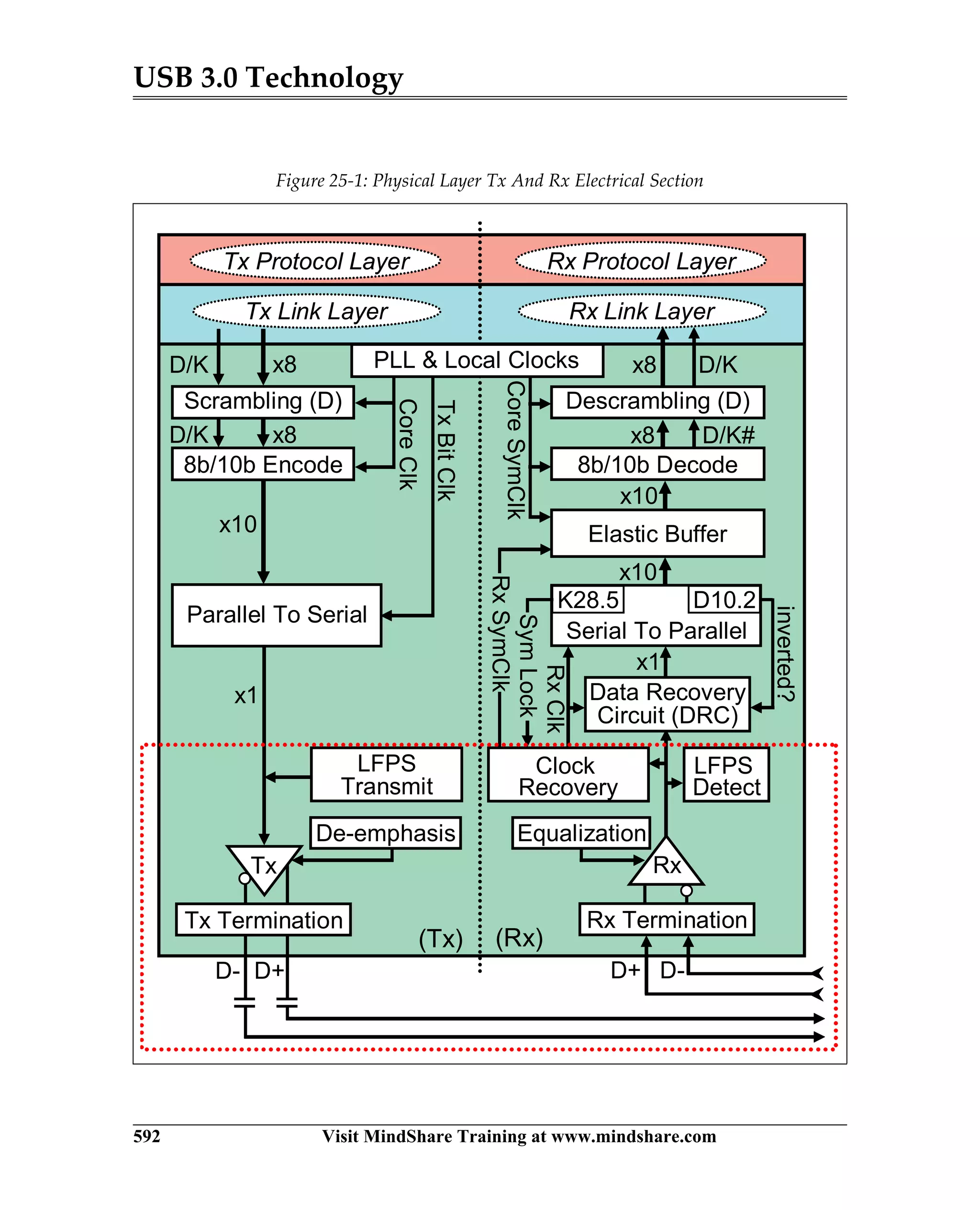
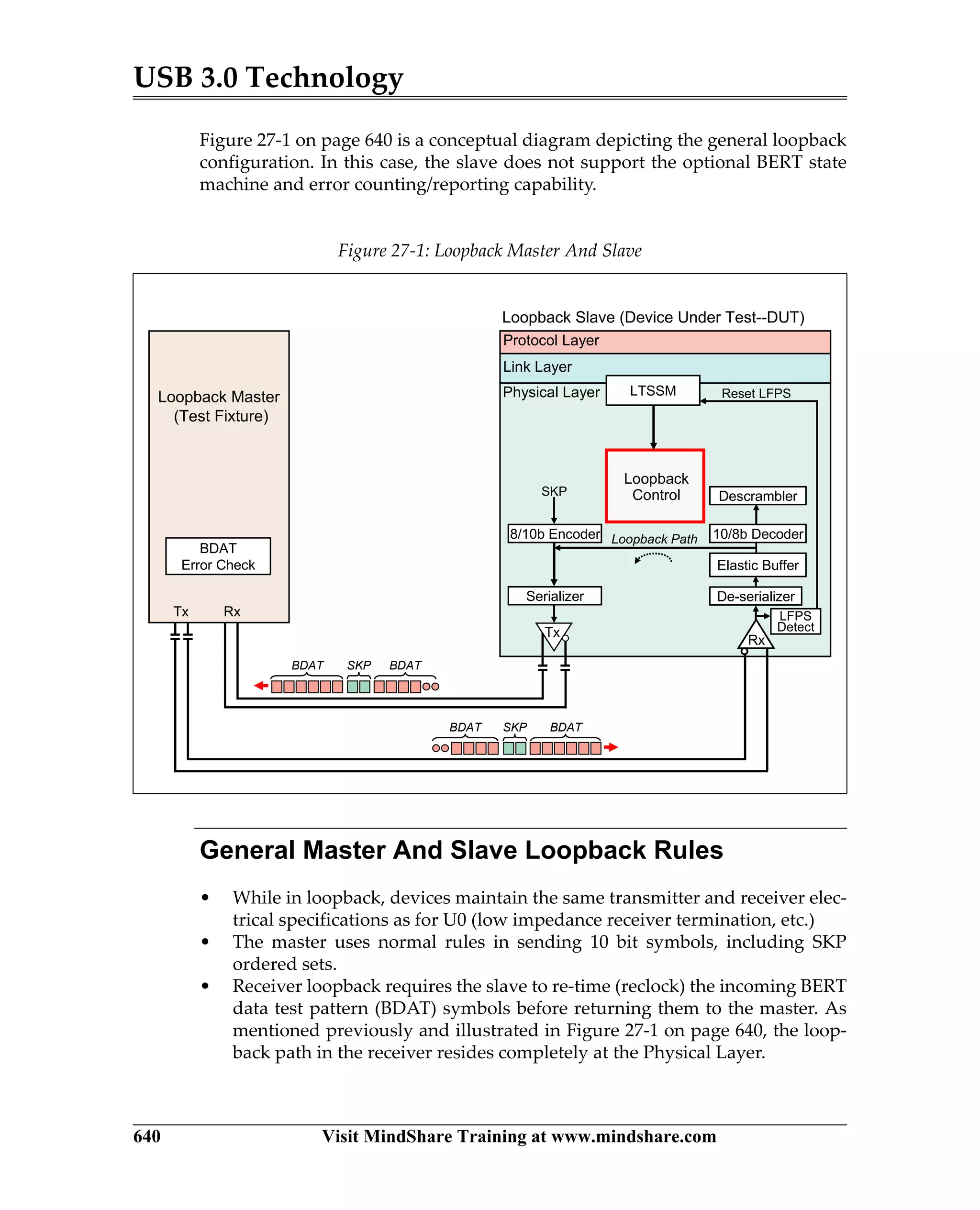
USB 3.0
TECHNOLOGY
MINDSHARE, INC.
Donovan (Don) Anderson
Jay Trodden
MindShare Training Courses
Click here to see a complete list of live and eLearning courses.
training@mindshare.com 1-800-633-1440 www.mindshare.com
Intel Architecture
• Intel Haswell Processor
• Intel 32/64 Bit x86 Architecture
• Intel QuickPath Interconnect (QPI)
• Computer Architecture
Big Data
• Hadoop
• Cassandra
• ElasticSearch
• MongoDB
Mobile Technology
• M-PCIe
• UFS
• MIPI M-PHY
• Intel-Based Mobile (Phone/Tablet)
• Intel Atom SoC
• Mobile DRAM (LPDDRx)
• High Speed/EMI for Mobile Platforms
IO Buses
• PCI Express 3.0
• PCIe IO Virtualization
• USB 3.0 / 2.0
• xHCI for USB
• USB 3.1 Update
AMD Architecture
• AMD Opteron Processor (Bulldozer)
• AMD64 Architecture
Virtualization Technology
• PC Virtualization
• IO Virtualization
• ARM Virtualization
Firmware Technology
• x86 Firmare (UEFI/BIOS) Architecture
• BIOS Essentials
Storage Technology
• SAS
• Serial ATA
• AHCI for SATA
• SATA 3.0
• NVMe
ARM Technology
• ARM Architecture
• ARM Virtualization
DRAM Technology
• DDRx & LPDDRx
• LPDDRx
Programming
• x86 Architecture Programming
• x86 Assembly Language Basics
• OpenCL Programming
High Speed Design
• High Speed Design
• EMI/EMC
The Ultimate Tool to
View, Edit and Verify
Configuration Settings
of Computers
MindShare Arbor is a computer system debug, validation, analysis and learning tool that allows
the user to read and write any memory, IO or configuration space address. The data from these
address spaces can be viewed in a clean and informative style. In addition, Arbor checks and
flags configuration errors and non-optimal settings.
Arbor’s Software Support
MindShare’s Arbor tool supports DOS, Windows and Linux 32- and 64-bit implementations and OS-X is near-
ing completion. In addition, Arbor supports Intel’s JTag debuggers.
View Reference Info
Arbor can quickly display standard PCI, PCI-X and PCIe configuration registers and memory structures. All the
register and field definitions are up-to-date with the PCI Express 3.0 implementation. Arbor also supports other
implementations such as the x86 MSRs, USB”s xHCI Host Controller and SATA’s AHCI Host Bus Adapter.
Other implementations are planned including, new x86 features and NVMe registers and data structures.
Decoding Standard and Custom Structures from a Live System
MindShare Arbor performs a system scan to record the PCI config space data, relevant memory and memory-
mapped structures as well as Model Specific Registers (MSRs) and shows them in a clean and intuitive
decoded format. MindShare Arbor also allows users to create their own decode files via XML.
Write Capability
MindShare Arbor provides a very simple interface to directly edit a register in PCI config space, memory
address space, IO address space or MSR. This can be done in the decoded view so you see what the mean-
ing of each bit, or by simply writing a hex value to the target location.
Scripting Capability
MindShare Arbor can also be used in a testing environment with compliance test suites, regression testing,
system setup for bug evaluation and more. Arbor can run Python scripts which allow users to automate any
functionality that can be performed manually from the graphical interface (and even more). MindShare pro-
vides several useful python scripts with the purchase of Arbor related to PCIe testing.
Run Rule Checks of Standard and Custom Structures
In addition to capturing and displaying headers and capability structures from PCI config space, Arbor can also
check the settings of each field for errors (e.g. violates the spec) and non-optimal values (e.g. a PCIe link
trained to something less than its max capability). MindShare Arbor has scores of these checks built in and
can be run on any system scan (live or saved). Any errors or warnings are flagged and displayed for easy
evaluation and debugging. Users can also define their own rule checks. These rule checks can be for any
structure, or set of structures, in PCI config space, memory space or IO space.
Saving System Scans (XML)
After a system scan has been performed, MindShare Arbor allows saving of that system's scanned data (PCI
config space, memory space and IO space) all in a single file to be looked at later or sent to a colleague. The
scanned data in these Arbor system scan files (.ARBSYS files) are XML-based and can be looked at with any
text editor or web browser. Even scans performed with other tools can be easily converted to the Arbor XML
format and evaluated with MindShare Arbor.
USB 3.0
TECHNOLOGY
MINDSHARE, INC.
Donovan (Don) Anderson
Jay Trodden
Many of the designations used by manufacturers and sellers to distinguish their prod-
ucts are claimed as trademarks. Where those designators appear in this book, and Mind-
Share was aware of the trademark claim, the designations have been printed in initial
capital letters or all capital letters.
The authors and publisher have taken care in preparation of this book, but make no
expressed or implied warranty of any kind and assume no responsibility for errors or
omissions. No liability is assumed for incidental or consequential damages in connec-
tion with or arising out of the use of the information or programs contained herein.
Library of Congress Cataloging-in-Publication Data
Anderson, Don and Trodden, Jay
USB 3.0 Technology / MindShare, Inc. Donovan Anderson, Jay Trodden....[et al.]
Includes index
ISBN: 978-0-9836465-1-8
1. Computer Architecture 2. Microcomputers - buses.
I. Anderson, Don II. MindShare, Inc. III. Title
Library of Congress Number:
ISBN: 978-0-9836465-1-8
Copyright ©2013 by MindShare, Inc.
All rights reserved. No part of this publication may be reproduced, stored in a retrieval
system, or transmitted, in any form or by any means, electronic, mechanical, photocopy-
ing, recording, or otherwise, without the prior written permission of the publisher.
Printed in the United States of America.
Sponsoring Editor:
Project Manager: Maryanne Daves
Cover Design: Greenhouse Creative and MindShare, Inc.
Set in 10 point Palatino Linotype by MindShare, Inc.
First Edition, First Printing,
Table of Contents
ix
About This Book
Scope............................................................................................................................................. 1
The MindShare Architecture Series ....................................................................................... 1
Cautionary Note ......................................................................................................................... 3
The Standard Is the Final Word .............................................................................................. 3
Documentation Conventions................................................................................................... 3
Hexadecimal Notation ........................................................................................................ 3
Binary Notation.................................................................................................................... 3
Decimal Notation................................................................................................................. 4
Bits Versus Bytes Notation ................................................................................................. 4
Bit Fields................................................................................................................................ 4
Other Terminology and Abbreviations ................................................................................. 4
Visit Our Web Site..................................................................................................................... 5
We Want Your Feedback........................................................................................................... 6
Chapter 1: Motivation for USB 3.0
Introduction................................................................................................................................. 7
USB 3.0 Host Controllers .......................................................................................................... 8
Performance................................................................................................................................. 8
USB Bandwidth Comparison ............................................................................................. 8
Streaming Video and Audio............................................................................................. 10
Mass Storage....................................................................................................................... 10
Improved Protocols.................................................................................................................. 11
End-to-End Protocols ........................................................................................................ 11
Token/Data/Handshake Shortcomings and Improvements................................. 11
Token/Data/Handshake is Inefficient............................................................... 12
Broadcast Bus Increases Power Consumption................................................ 13
Polled Flow Control. ........................................................................................... 13
Error Handling and Reporting .......................................................................... 13
Data Bursting............................................................................................................... 14
Bulk Streaming............................................................................................................ 14
Port-to-Port Protocols........................................................................................................ 14
Link Flow Control....................................................................................................... 15
Link Error Detection and Recovery ......................................................................... 15
Power Management ................................................................................................................. 15
SuperSpeed Bus Power Management............................................................................. 15
Broadcast Versus Unicast Bus................................................................................... 15
Link Power Management .......................................................................................... 16
Function Power Management................................................................................... 16
System Power Improvements .......................................................................................... 16
USB 3.0 Technology
x
Chapter 2: USB 2.0 Background
Motivations for USB................................................................................................................ 17
USB Topologies........................................................................................................................ 18
USB 2.0 Companion Controllers...................................................................................... 19
Host Controller Registers.................................................................................................. 20
USB Hubs ............................................................................................................................ 22
Root Hubs .................................................................................................................... 22
External Hubs.............................................................................................................. 23
Hub Depth Limits....................................................................................................... 25
Broadcast Transactions...................................................................................................... 26
Device Architecture ................................................................................................................. 28
Endpoints and Buffers....................................................................................................... 29
Control Endpoints.............................................................................................................. 30
Standard Requests ............................................................................................................. 31
Optional Endpoints ........................................................................................................... 32
USB 2.0 Packets and Protocol................................................................................................. 33
Token-Data-HandShake Packet Protocol ....................................................................... 33
IN Transactions........................................................................................................... 34
OUT Transactions....................................................................................................... 35
Low-Speed Transaction Variation............................................................................ 35
Control Transfer Stages.............................................................................................. 36
Three-Stage Transfers ......................................................................................... 36
Two-Stage Transfers............................................................................................ 36
Maximum Payload Sizes ........................................................................................... 37
HS Ping Protocol - For OUT Transactions...................................................................... 37
HS Split Transaction Protocol .......................................................................................... 39
Transaction Generation and Scheduling............................................................................. 41
Transaction Generation..................................................................................................... 42
Transaction Scheduling..................................................................................................... 43
Device Power ............................................................................................................................ 45
Chapter 3: USB 3.0 Overview
USB 3.0 Topology and Compatibility .................................................................................. 47
USB 3.0 Host Controller.................................................................................................... 49
Topology ............................................................................................................................. 49
USB 2.0/3.0 Compatibility................................................................................................. 50
Receptacle and Plug Compatibility.......................................................................... 50
SuperSpeed Device Compatibility ........................................................................... 51
Software Compatibility.............................................................................................. 51
The SuperSpeed Physical Layer Environment................................................................... 51
Table of Contents
xi
USB 3.0 Composite Cable ................................................................................................. 51
SS Link Models............................................................................................................ 52
Shared Bus Power....................................................................................................... 53
USB 3.0 Compliant Cable Assemblies............................................................................. 54
General ......................................................................................................................... 54
USB 3.0 Power-B Connections .................................................................................. 54
SuperSpeed Layered Interface and Protocols..................................................................... 56
Hub Interface Layers ......................................................................................................... 58
Layers - Hub Forwarding Packets............................................................................ 58
Layers - Hub as Target............................................................................................... 58
Layers - Hub Downstream Port (Thin Protocol Layer)......................................... 60
Three Protocols................................................................................................................... 61
End-to-End Protocol (Protocol Layer) ..................................................................... 61
USB 2.0 vs SS IN Transaction Comparison...................................................... 62
USB 2.0 vs SS OUT Transaction Comparison.................................................. 63
Port-to-Port Protocol (Link Layer) ........................................................................... 64
Chip-to-Chip Protocol (Physical Layer) .................................................................. 66
Configuration and Descriptors.............................................................................................. 66
Power Management ................................................................................................................. 67
Link Power Management.................................................................................................. 68
Function Power Management.......................................................................................... 69
Chapter 4: Introduction to End-to-End Protocol
The Protocols............................................................................................................................. 71
The Protocol Packet Types................................................................................................ 72
The Token Lives On........................................................................................................... 72
Bursting ............................................................................................................................... 73
Bulk Endpoint Streaming ................................................................................................. 74
Endpoint Characteristics for SuperSpeed ...................................................................... 76
Port-to-Port Protocol Influence.............................................................................................. 76
Does SuperSpeed Support Parallel Operations?............................................................... 77
Chapter 5: End-to-End Packets
Three Categories of End-To-End Packets............................................................................ 79
Transaction Packets (TPs)....................................................................................................... 82
ACK Header ....................................................................................................................... 83
Downstream Moving ACK........................................................................................ 83
Upstream Moving ACK............................................................................................ 85
NRDY Header..................................................................................................................... 86
ERDY Header ..................................................................................................................... 88
STATUS Header................................................................................................................. 89
USB 3.0 Technology
xii
STALL Header.................................................................................................................... 91
Notification Headers ......................................................................................................... 92
Function Wake Header .............................................................................................. 92
Latency Tolerance Message Header......................................................................... 94
Bus Interval Adjustment Message Header ............................................................. 95
PING and PING RESPONSE Header.............................................................................. 96
Data Packet................................................................................................................................ 99
DATA Packet Moving Downstream ............................................................................... 99
DATA Packet Moving Upstream................................................................................... 101
Isochronous Timestamp Packet (ITP) ................................................................................ 103
Chapter 6: Control Protocol
Introduction to SuperSpeed Control Transfers ............................................................... 105
Control Transfer Structures and Examples....................................................................... 106
Two-Stage Control Transfer Structure.......................................................................... 107
Three-Stage Control Transfer Structure........................................................................ 107
Control IN Example — Single Data Packet........................................................... 108
Control IN Example — Two Data Packets............................................................ 109
Control OUT Example — Two DATA Packets .................................................... 109
Control Transfer Packet Content ........................................................................................ 110
The Setup Transaction..................................................................................................... 110
The DATA Header Packet....................................................................................... 110
Data Packet Payload — Setup Data ....................................................................... 111
Setup Response — ACK .......................................................................................... 114
DATA Stage ...................................................................................................................... 114
Status Stage ....................................................................................................................... 115
General ....................................................................................................................... 115
Control Transfer with STALL ................................................................................. 115
Two Stage Control Transfer Example ................................................................................ 116
Set Address Request ........................................................................................................ 116
Setup Stage — Set Address ..................................................................................... 116
Status Stage — Set Address..................................................................................... 117
Protocol Details for Set Address Request..................................................................... 117
Three Stage IN Control Transfer Examples...................................................................... 119
The Get Device Descriptor Request Example.............................................................. 119
Setup Transaction — Get Device Descriptor ........................................................ 119
Data and Status Stages — Get Device Descriptor................................................ 120
Protocol Details — Get Device Descriptor Request............................................. 120
Control Transfer — Variable-Length Data Example 1 ............................................... 122
Control Transfer — Variable-Length Data Example 2 ............................................... 123
Table of Contents
xiii
Chapter 7: Bulk Protocol
Introduction to Bulk Transfers............................................................................................ 125
Bulk End-to-End Protocol..................................................................................................... 126
Bulk IN SuperSpeed Transaction Protocol................................................................... 127
IN Data Bursting....................................................................................................... 127
Single DATA Packet Burst Example............................................................... 129
Burst IN Example with Four DATA Packets................................................. 130
Burst IN Example with Long Burst................................................................. 131
End-to-End Flow Control — Bulk IN Transfers................................................... 132
NRDY Flow Control at Start of IN Transfer .................................................. 132
IN Burst Flow Control Using EOB.................................................................. 133
IN Burst Flow Control Using NRDY .............................................................. 134
Short packets ...................................................................................................... 135
Data IN Transfer Errors and Retry.................................................................. 136
Bulk OUT SuperSpeed Transaction Protocol............................................................... 137
OUT Data Bursting................................................................................................... 138
Single DATA OUT Burst Example.................................................................. 138
Burst OUT Example with Four DATA Packets............................................. 139
Burst OUT Example with Long Burst............................................................. 140
End-to-End Flow Control — Bulk OUT Transfers............................................... 141
NRDY Flow Control at Start of OUT Transfer .............................................. 142
OUT Burst Flow Control Using NumP=0 ...................................................... 143
DATA OUT Transfer Errors............................................................................. 144
Timeout conditions and values...................................................................................... 146
Standard Bulk Vs. Bulk Streaming Endpoints................................................................. 146
Streaming And Endpoint Buffers ....................................................................................... 147
Standard Bulk Endpoint Buffer ..................................................................................... 147
Bulk Streaming Endpoint Buffers.................................................................................. 148
Stream ID (SID), A Bit More........................................................................................... 148
Priming the Bulk Streaming Endpoints........................................................................ 149
Reporting Bulk Endpoint Streaming Capability ............................................................. 149
Standard And Bulk Streaming Examples.......................................................................... 150
Standard Bulk Endpoints & SCSI BOT Drive .............................................................. 150
UAS Device Endpoints............................................................................................. 151
Host Memory Buffers............................................................................................... 152
Host Controller (HC)................................................................................................ 152
BOT Disk DMA Read Operation............................................................................ 153
Bulk Streaming Endpoints & UAS Drive ..................................................................... 154
UAS Device Endpoints............................................................................................. 155
Host Memory Buffers............................................................................................... 156
Host Controller (HC)................................................................................................ 157
USB 3.0 Technology
xiv
Example UAS and UASP Commands........................................................................... 157
The Non-Data UAS Command............................................................................... 158
Non Data UASP Command .................................................................................... 159
Read DMA UAS Command.................................................................................... 160
Read DMA UASP Command.................................................................................. 162
Write DMA UAS Command ................................................................................... 164
Write DMA UASP Command................................................................................. 165
Chapter 8: Interrupt Protocol
Introduction to Interrupt Transfers.................................................................................... 167
Interrupt IN SuperSpeed Transaction Protocol ............................................................... 169
Single Interrupt Transaction........................................................................................... 169
Burst transaction sequence (two DATA packets)........................................................ 170
Interrupt IN — Errors and Retries................................................................................. 173
Interrupt OUT SuperSpeed Transaction Protocol....................................................... 176
Interrupt OUT Data Bursting.................................................................................. 176
End-to-End Flow Control — Interrupt OUT Transfers....................................... 177
Chapter 9: Isochronous Protocol
Introduction to Isochronous Transfers .............................................................................. 181
Bus Intervals and Isochronous Service Intervals............................................................. 183
Flexibility of Scheduling ...................................................................................................... 184
Isochronous Timestamp Packet Delivery.......................................................................... 185
General............................................................................................................................... 185
The Timestamp Packet .................................................................................................... 186
Delta Value ................................................................................................................ 187
Delayed Bit................................................................................................................. 187
Changing the Time Base....................................................................................................... 187
Requirements for Changing the TimeBase................................................................... 187
Bus Interval Adjustment Message................................................................................. 188
Ping and Ping Response ....................................................................................................... 189
Ping Related Timing Parameters ................................................................................... 190
Maximum Exit Latency (MEL) ............................................................................... 190
tPingTimeout............................................................................................................. 190
Ping and Ping Response Header Format...................................................................... 191
Isochronous End-to-End Protocol ....................................................................................... 192
General Isochronous IN Protocol Rules ....................................................................... 192
Isochronous IN Protocol ................................................................................................. 192
Isochronous IN with Burst of Two......................................................................... 193
Isochronous IN Burst of Two with Zero Payload................................................ 194
Isochronous IN Burst Size of 16.............................................................................. 195
Table of Contents
xv
Isochronous OUT Transactions...................................................................................... 196
Isochronous OUT with Burst Size of 16................................................................. 196
Isochronous OUT Burst with Four Service Intervals........................................... 197
Service Interval N .............................................................................................. 197
Service interval N+1 .......................................................................................... 197
Service Interval N+2 .......................................................................................... 197
Service Interval N+3 .......................................................................................... 197
Smart Isochronous Transaction Scheduling..................................................................... 198
Smart Isochronous IN Transaction Example ............................................................... 199
Smart Isochronous IN Transactions with No Ping ..................................................... 202
Smart Isochronous OUT Transactions.......................................................................... 203
Chapter 10: USB 3.0 Hubs
Introduction to SS Hubs ....................................................................................................... 205
Hub Attachment ..................................................................................................................... 207
Packet Forwarding ................................................................................................................. 207
Packet Forwarding and the Layers................................................................................ 209
Packet Routing Across Hub — Link-to-Link........................................................ 209
Packet Routing to Hub Controller.......................................................................... 210
Packet Routing to Hub Controller with LMP....................................................... 210
Unicast Routing................................................................................................................ 212
Packet Forwarding and Buffer Requirements ............................................................. 213
Header Buffers — Store and Forward Model....................................................... 214
Data Payload Buffers — The Repeater Model...................................................... 215
Transaction Deferral........................................................................................................ 216
Hub Error Detection and Handling.................................................................................... 218
Hub Link Power Management Responsibilities.............................................................. 219
Cable Power and Distribution............................................................................................. 220
Reset Propagation................................................................................................................... 220
Chapter 11: Introduction to Port-To-Port Protocol
Port-To-Port Protocol And The Link Layer....................................................................... 221
The Big Picture Revisited ..................................................................................................... 222
Port-To-Port Protocol: Header Processing......................................................................... 223
General............................................................................................................................... 223
Header Fields, Two Groups ........................................................................................... 223
Link Layer Header Processing Elements ........................................................................... 224
Tx HP Processing ............................................................................................................. 225
Tx HP Buffers.................................................................................................................... 225
Tx Data CRC-32 Generation ........................................................................................... 225
Rx HP Checks ................................................................................................................... 226
USB 3.0 Technology
xvi
Rx HP Buffers ................................................................................................................... 226
Rx Data CRC-32 Checking.............................................................................................. 226
Link Management Elements ................................................................................................ 227
LTSSM Functional Block................................................................................................. 228
Tx, Rx Link Commands................................................................................................... 228
Link Command Groups .................................................................................................. 228
Packet Acknowledgement Link Commands ........................................................ 229
Flow Control Link Commands............................................................................... 229
Power Management Link Commands................................................................... 229
Link Up/Link Down Link Commands................................................................... 229
HP Acknowledgement.................................................................................................... 230
HP Flow Control .............................................................................................................. 230
Ordered Sets............................................................................................................................ 231
Ordered Set Data (D) and Control (K) Symbols.......................................................... 231
Four Ordered Set Functional Groups............................................................................ 232
Framing Ordered Sets (Delimiters)........................................................................ 232
Header Packet Framing .................................................................................... 232
Data Packet Framing (Valid Data Payload)................................................... 233
Data Packet Framing (Nullified Data Payload) ............................................ 234
Link Command Framing.................................................................................. 235
Link Training & Retraining Ordered Sets............................................................. 236
TSEQ Ordered Set.............................................................................................. 236
TS1 Ordered Set ................................................................................................. 237
TS2 Ordered Set ................................................................................................. 238
Clock Compensation Ordered Set (Skip Ordered Set)........................................ 239
Loopback Bit Error Rate Test (BERT) Ordered Sets............................................. 240
General ................................................................................................................ 240
BRST Ordered Set.............................................................................................. 241
BERC Ordered Set ............................................................................................. 241
BCNT Ordered Set............................................................................................. 242
Chapter 12: LTSSM And the SuperSpeed Link States
Twelve High Level LTSSM States...................................................................................... 244
Why Is The LTSSM Needed?............................................................................................... 245
LTSSM And Link Training And Retraining................................................................. 245
Background: USB 2.0 Doesn’t Require Training .................................................. 245
LTSSM Coordinates SuperSpeed Link Training .................................................. 245
LTSSM And Link-Level Error Handling ...................................................................... 246
Background: USB 2.0 Approach to Bus Errors..................................................... 246
USB 3.0 SuperSpeed Approach To Link Errors.................................................... 247
When Does The LTSSM Become Involved?.......................................................... 247
LTSSM And SuperSpeed Link Power Management................................................... 248
Table of Contents
xvii
Background: USB 2.0 Power Management ........................................................... 248
USB 3.0 SuperSpeed Power Management Enhancements.................................. 248
The LTSSM Role In SuperSpeed Link Power Management............................... 248
LTSSM And SuperSpeed Link Testing ......................................................................... 249
Background: USB 2.0 Testing.................................................................................. 249
USB 3.0 SuperSpeed Link Testing Features .......................................................... 249
LTSSM State Transitions...................................................................................................... 250
General............................................................................................................................... 250
What Is A Directed LTSSM Transition?........................................................................ 250
Handshake Signaling Locks LTSSMs............................................................................ 250
LTSSM Handshake Takes Several Forms..................................................................... 251
LFPS Signaling Events Used In LTSSM Handshake ........................................... 251
Ordered Sets Used In LTSSM Handshake ............................................................ 252
Link Commands Used In LTSSM Handshake...................................................... 253
LTSSM Time-outs............................................................................................................. 254
General ....................................................................................................................... 254
Timer Characteristics................................................................................................ 254
LTSSM Reference Section Note.......................................................................................... 256
Summary Of LTSSM Operational States .......................................................................... 256
U0 ....................................................................................................................................... 256
General Description.................................................................................................. 257
Requirements In The U0 State ................................................................................ 257
Exit Rules For The U0 State..................................................................................... 257
U1 ....................................................................................................................................... 259
General Description.................................................................................................. 259
Requirements In The U1 State ................................................................................ 259
Exit Rules For The U1 State..................................................................................... 260
U2 ....................................................................................................................................... 261
General Description.................................................................................................. 261
Requirements In The U2 State ................................................................................ 261
Exit Rules For The U2 State..................................................................................... 262
U3 (Suspend) .................................................................................................................... 263
General Description.................................................................................................. 263
Requirements In The U3 State ................................................................................ 263
Exit Rules For The U3 State..................................................................................... 264
Summary Of LTSSM Link Initialization &Training States .......................................... 265
Rx.Detect ........................................................................................................................... 265
General Description.................................................................................................. 265
Requirements In The Rx.Detect.Reset Substate.................................................... 266
Exit Rules For The Rx.Detect.Reset Substate ........................................................ 266
Requirements In The Rx.Detect.Active Substate.................................................. 266
Exit Rules For The Rx.Detect.Active Substate ...................................................... 267
USB 3.0 Technology
xviii
Requirements In The Rx.Detect.Quiet Substate ................................................... 267
Exit Rules For The Rx.Detect.Quiet Substate........................................................ 268
Polling................................................................................................................................ 268
General Description.................................................................................................. 268
Requirements In The Polling.LFPS Substate ........................................................ 269
Exit Rules For The Polling.LFPS Substate............................................................. 269
Requirements In The Polling.RxEQ Substate ....................................................... 270
Exit Rules For The Polling.RxEQ Substate............................................................ 270
Requirements In The Polling.Active Substate ...................................................... 271
Exit Rules For The Polling.Active Substate........................................................... 271
Requirements In The Polling.Configuration Substate......................................... 272
Exit Rules For The Polling.Configuration Substate ............................................. 272
Requirements In The Polling.Idle Substate........................................................... 273
Exit Rules For The Polling.Idle Substate ............................................................... 273
Recovery............................................................................................................................ 274
General Description.................................................................................................. 275
Requirements In Recovery.Active.......................................................................... 275
Exit Rules For Recovery.Active .............................................................................. 275
Requirements In Recovery.Configuration ............................................................ 276
Exit Rules For Recovery.Configuration................................................................. 276
Requirements In Recovery.Idle............................................................................... 277
Exit Rules For Recovery.Idle................................................................................... 277
Hot Reset ........................................................................................................................... 278
General Description.................................................................................................. 278
Requirements In Hot Reset.Active......................................................................... 278
Exit Rules For Hot Reset.Active.............................................................................. 279
Requirements In Hot Reset.Exit.............................................................................. 279
Exit Rules For Hot Reset.Exit .................................................................................. 280
Summary Of LTSSM Testing States .................................................................................. 281
Compliance Mode............................................................................................................ 281
General Description.................................................................................................. 281
Requirements In Compliance Mode ...................................................................... 282
Exit Rules For Compliance Mode........................................................................... 282
Loopback........................................................................................................................... 283
General Description.................................................................................................. 283
Requirements In Loopback.Active......................................................................... 283
Exit Rules For Loopback.Active ............................................................................. 284
Requirements In Loopback.Exit.............................................................................. 284
Exit Rules For Loopback.Exit.................................................................................. 284
Summary Of Other LTSSM States ..................................................................................... 285
SS.Inactive State................................................................................................................ 285
General Description.................................................................................................. 285
Table of Contents
xix
Basic SS.Inactive Requirements .............................................................................. 285
Requirements In SS.Inactive.Quiet Substate......................................................... 286
Exit Rules For SS.Inactive.Quiet Substate ............................................................. 286
Requirements In SS.Inactive.Disconnect.Detect................................................... 286
Exit Rules For SS.Inactive.Disconnect.Detect ....................................................... 286
SS.Disabled State.............................................................................................................. 287
General Description.................................................................................................. 287
Exit Rules For The SS.Disabled State ..................................................................... 288
Requirements For The SS.Disabled.Default Substate.......................................... 288
Exit Rules For The SS.Disabled.Default Substate................................................. 288
Exit Rules For The SS.Disabled.Error Substate..................................................... 288
Chapter 13: Link Commands
Four Groups Of Link Commands....................................................................................... 289
Link Commands On The SuperSpeed Link ..................................................................... 291
For Additional Details On Link Commands .................................................................... 291
Link Command Encoding And Use.................................................................................... 292
Packet Acknowledgement: LGOOD_n......................................................................... 292
Packet Acknowledgement: LBAD................................................................................. 293
Packet Acknowledgement: LRTY.................................................................................. 294
Flow Control: LCRD_x.................................................................................................... 295
Power Management: LGO_Ux (The Request) ............................................................. 296
Power Management: LAU (Acceptance)...................................................................... 297
Power Management: LXU (Rejection)........................................................................... 298
Power Management: LPMA (Acknowledgement)...................................................... 299
Link Up/Link Down: LDN.............................................................................................. 300
Link Up/Link Down: LUP .............................................................................................. 301
Notes On Link Command Placement................................................................................. 302
Chapter 14: Header Packet Processing
Link Layer Packet Processing Role..................................................................................... 303
Transmitter Packet Processing............................................................................................. 305
Header Sequence Number Assignment ....................................................................... 306
Header Link Control Word CRC-5 Generated ............................................................ 307
Header CRC-16 Generated ............................................................................................. 308
Copy Is Placed In A Header Packet Buffer .................................................................. 309
Data Packet Payload CRC-32 Generation..................................................................... 310
General ....................................................................................................................... 310
Tx DPP CRC-32 Generation, The Hardware Details ........................................... 311
Framing Added, Packet Sent To Physical Layer ......................................................... 312
Receiver Packet Processing .................................................................................................. 313
USB 3.0 Technology
xx
Inbound Link Layer Traffic ............................................................................................ 313
Key Header Packet Processing Elements ..................................................................... 314
Header Packet CRC-16 Checked.................................................................................... 315
Header Link Control Word CRC-5 Checked ............................................................... 316
Header Sequence Number Checked ............................................................................. 317
Header Packet Buffer Accepts The Header.................................................................. 318
Data Packet Payload (DPP) CRC-32 Checked ............................................................. 319
General ....................................................................................................................... 319
Rx DPP CRC-32 Checking, The Hardware Details.............................................. 320
Chapter 15: Header Packet Flow Control
Background: Host And Device Flow Control................................................................... 321
USB 2.0 Flow Control, Very Limited............................................................................. 322
The SuperSpeed Flow Control Approach .................................................................... 322
End To End Flow Control........................................................................................ 322
Link Level Flow Control Is Also Needed.............................................................. 323
SuperSpeed Link Level Flow Control Basics ................................................................... 324
Flow Control Elements.......................................................................................................... 325
Transmitter Elements ...................................................................................................... 326
Tx Header Packet (HP) Buffers............................................................................... 326
Remote Rx HP Credit Count................................................................................... 326
Credit _HP_Timer..................................................................................................... 326
Next Rx LCRD_x....................................................................................................... 327
Receiver Elements............................................................................................................ 327
Rx Header Packet (HP) Buffers............................................................................... 327
LCRD_x Generation ................................................................................................. 327
Header Packet Flow Control Link Commands................................................................. 328
General............................................................................................................................... 328
LCRD_x Link Command Format................................................................................... 328
Flow Control Initialization................................................................................................... 329
Flow Control Logic State After Reset............................................................................ 329
Flow Control Logic Initialization................................................................................... 330
Flow Control During Normal Operations......................................................................... 331
The First Header Is Sent.................................................................................................. 331
Header Packet Reaches Rx HP Buffer........................................................................... 332
Emptying An Rx HP Buffer............................................................................................ 333
Transmitter Receives LCRD_x ....................................................................................... 334
If Tx Receives A Valid LCRD_x..................................................................................... 335
If Tx Receives An Invalid LCRD_x................................................................................ 336
Table of Contents
xxi
Chapter 16: Link Errors & Packet Acknowledgement
Background: USB 2.0 Error Handling ................................................................................ 339
USB 3.0 SuperSpeed Requires A New Approach............................................................ 340
SuperSpeed Signaling Affects Bit Error Rates ............................................................. 340
Complex USB Topologies A Challenge At 5 Gb/s....................................................... 340
Upstream Asynchronous Message Errors.................................................................... 341
Scope Of SuperSpeed Link Errors...................................................................................... 342
Training Sequence Errors................................................................................................ 343
Errors Occurring While Link is in U0 ........................................................................... 343
SuperSpeed Link Level Error Correction Approach ....................................................... 343
Goals Of Header Packet Acknowledgement ............................................................... 344
Reliable Delivery Of Header Packets..................................................................... 344
Hand Off The More Serious Errors ........................................................................ 344
End-To-End Acknowledgement Is Still Needed ......................................................... 345
Header Packet Acknowledgement Elements.................................................................... 345
Transmitter Elements ...................................................................................................... 346
HDR Seq# Assignment............................................................................................. 346
Next Tx HDR Seq#.................................................................................................... 347
HDR CRC-5................................................................................................................ 347
HDR CRC-16.............................................................................................................. 347
Tx HP (Header Packet) Buffers............................................................................... 347
Pending_HP_Timer.................................................................................................. 347
Next Rx LGOOD_n................................................................................................... 348
Receiver Elements............................................................................................................ 349
HDR CRC-5 And CRC-16 Checks .......................................................................... 349
Retries (Retry attempt counter) .............................................................................. 349
LBAD Generation ..................................................................................................... 350
HDR Seq# Check....................................................................................................... 350
Next Rx HDR Seq#.................................................................................................... 350
Rx Header Packet (HP) Buffers............................................................................... 351
LGOOD_n Generation ............................................................................................. 351
Header Packet Acknowledgement Link Commands ...................................................... 351
LGOOD_n Link Command Format .............................................................................. 352
LBAD Link Command Format....................................................................................... 353
LRTY Link Command Format ....................................................................................... 354
Header Packet Acknowledgement Initialization............................................................. 355
HP Acknowledgement Logic After Reset .................................................................... 355
HP Sequence Number Advertisement.......................................................................... 356
General ....................................................................................................................... 356
Sequence Of Events .................................................................................................. 357
HP Acknowledgement Sequence: No Retry Required ................................................... 357
USB 3.0 Technology
xxii
First Header Packet Is Sent............................................................................................. 357
Header CRC-5, CRC-16 Checked By The Receiver..................................................... 359
Header Sequence Number Checked By Receiver ....................................................... 360
Receiver Accepts And Acknowledges The Packet...................................................... 361
Transmitter Checks LGOOD_n Acknowledgement................................................... 362
LGOOD_n Valid: Retire Header Packet ....................................................................... 363
HP Acknowledgement Sequence: Retry Required.......................................................... 364
The Header Packet Is Sent .............................................................................................. 364
Header CRC-5 or CRC-16 Check Fails, LBAD Sent .................................................... 365
Transmitter Receives LBAD, Starts The Retry............................................................. 366
Retry Header Packet CRC-5, CRC-16 Checked ........................................................... 367
Retry Header Packet Sequence Number Checked...................................................... 368
Receiver Acknowledges The Retry Header Packet..................................................... 369
Transmitter Checks LGOOD_n Following The Retry ................................................ 370
LGOOD_n Valid: Retire The Header Packet................................................................ 371
Chapter 17: Introduction to Chip-To-Chip Protocol
Chip-To-Chip Protocol And The Physical Layer ............................................................. 373
The Big Protocol Picture, Once More................................................................................. 374
Chip-To-Chip Protocol: PHY Logical Processing............................................................. 375
A Note About D/K Bytes And Symbols........................................................................ 375
A Few Common Structure D/K Examples ................................................................... 376
The Physical Layer: PHY Logical Processing.................................................................... 377
Tx Scrambling................................................................................................................... 378
Tx 8b/10b Encoding ......................................................................................................... 378
Tx Serialization................................................................................................................. 378
Rx Clock/Data Recovery ................................................................................................. 378
Rx De-serialization........................................................................................................... 378
Rx Elastic Buffer ............................................................................................................... 379
Rx 8b/10b Decoding......................................................................................................... 379
Rx De-scrambling............................................................................................................. 379
Receiver PHY Forwards Traffic to Link Layer ............................................................ 379
The Physical Layer: PHY Electrical Specifications.......................................................... 379
General Topics.................................................................................................................. 381
Transmitter PHY Electrical Topics ................................................................................ 381
Receiver PHY Electrical Topics...................................................................................... 381
Low Frequency Periodic Signaling (LFPS)................................................................... 381
Table of Contents
xxiii
Chapter 18: Physical Layer Logical Functions
Physical Layer Logic Definitions........................................................................................ 383
Tx Physical Layer (PHY) Logic ............................................................................................ 385
Tx Outbound Bytes And The D/K Flag ........................................................................ 385
Data Scrambling............................................................................................................... 386
General ....................................................................................................................... 386
Disabling Scrambling ............................................................................................... 388
8b/10b Encoding............................................................................................................... 388
The Purpose Of Encoding........................................................................................ 389
Two Key 8b/10b Encoding Rules............................................................................ 390
Some 8b/10b Encoding Examples........................................................................... 390
8b/10b Encoding And Current Running Disparity.............................................. 391
The AC-Coupled SuperSpeed Link........................................................................ 392
Advantages of AC-Coupling ........................................................................... 392
Challenges of AC-Coupling............................................................................. 392
8b/10b Encoding Minimizes Disparity .................................................................. 392
Is The Transmitter CRD Choice Correct?.............................................................. 393
Parallel To Serial Data Conversion................................................................................ 394
Differential Transmitter .................................................................................................. 395
Rx Physical Layer (PHY) Logic ............................................................................................ 396
Differential Receiver And Equalization........................................................................ 396
Clock And Data Recovery .............................................................................................. 397
Clock Recovery.......................................................................................................... 398
Data Recovery Circuit (DRC).................................................................................. 398
Serial To Parallel Data Conversion................................................................................ 399
Serial To Parallel Conversion and COM Symbol Lock ....................................... 400
Differential Polarity Inversion (If Needed)........................................................... 401
Elastic Buffer..................................................................................................................... 402
Tx And Rx Clock Requirements ............................................................................. 403
5 GHz Base Clock .............................................................................................. 403
Spread Spectrum Clocking............................................................................... 403
Implications Of Tx, Rx Clock Difference............................................................... 403
The Result: Two Rx Clock Domains....................................................................... 404
Receiver PHY Clock Domain Notes................................................................ 405
Elastic Buffer Architecture....................................................................................... 406
Skip (SKP) Ordered Sets .......................................................................................... 407
8b/10b Decode .................................................................................................................. 408
Error Checking At The Decoder............................................................................. 408
Decoded Data (D) And Control (K) Bytes............................................................. 409
Descrambling Of Data (D) Bytes.................................................................................... 410
Forwarding Traffic To Link Layer................................................................................. 411
USB 3.0 Technology
xxiv
Chapter 19: SuperSpeed Reset Events
PowerOn Reset ....................................................................................................................... 413
Software May Enable And Disable VBUS.................................................................... 414
PowerOn Reset Impact On Device State ...................................................................... 415
PowerOn Reset And Self-Powered Devices................................................................. 415
Warm Reset.............................................................................................................................. 416
How Warm Reset Is Signaled On The Link ................................................................. 417
After Warm Reset Completes......................................................................................... 418
Hot Reset.................................................................................................................................. 418
How Hot Reset Is Signaled On The Link...................................................................... 419
After Hot Reset Completes............................................................................................. 420
Hot Reset, The LTSSM View .......................................................................................... 420
General Description.................................................................................................. 421
Requirements In Hot Reset.Active......................................................................... 421
Exit Rules For Hot Reset.Active.............................................................................. 421
Requirements In Hot Reset.Exit.............................................................................. 422
Exit Rules For Hot Reset.Exit .................................................................................. 422
Notes About Warm Reset And Hot Reset Latency .......................................................... 423
Warm Reset Is Time Consuming, But Thorough ........................................................ 423
Hot Reset Is Much Faster, Not As Thorough............................................................... 423
How Does Software Know If Hot Reset Is Possible?...................................................... 423
The Two In-Band Reset Hub Requests.............................................................................. 424
SetFeature (BH_PORT_RESET)...................................................................................... 424
SetFeature (PORT_RESET) ............................................................................................. 424
Hubs Propagate Resets Downstream ................................................................................. 425
General............................................................................................................................... 425
Hub Reset Propagation, Key Rules ............................................................................... 426
Chapter 20: Link Training
Link Training Required Before SuperSpeed Operation ................................................ 427
USB Physical Connections Complicate Link Training ............................................... 428
The Long Channel..................................................................................................... 429
The Short Channel .................................................................................................... 429
SuperSpeed Link Training Is Adaptive ........................................................................ 429
Which Logic Requires Training?......................................................................................... 430
General............................................................................................................................... 430
Summary Of Key Link Training Elements................................................................... 431
Receiver Equalization............................................................................................... 431
Clock Recovery.......................................................................................................... 432
Data Recovery Circuit (DRC).................................................................................. 432
Table of Contents
xxv
Serial To Parallel Conversion and Symbol Lock.................................................. 433
Differential Polarity Inversion (If Needed)........................................................... 433
Elastic Buffer Initialization ...................................................................................... 433
Link Training Is Managed by LTSSM............................................................................... 434
The Normal Link Training Sequence ................................................................................ 435
Rx.Detect.Reset................................................................................................................. 435
Normal Exit From Rx.Detect.Reset ........................................................................ 436
Other Exits From Rx.Detect.Reset .......................................................................... 436
Rx.Detect.Active............................................................................................................... 437
SuperSpeed Receivers Enable & Disable Termination........................................ 438
Receiver Common Mode Input Impedance Range.............................................. 438
The Detection Method.............................................................................................. 439
Normal Exit: From Rx.Detect.Active To Polling .................................................. 441
Alternative Exit: From Rx.Detect.Active To Rx.Detect.Quiet............................. 441
Other Exits From Rx.Detect.Active ........................................................................ 441
Rx.Detect.Quiet ................................................................................................................ 442
Polling.LFPS...................................................................................................................... 443
The Polling.LFPS Burst Format .............................................................................. 443
Other Polling.LFPS Requirements And Options ................................................. 444
Normal Exit: From Polling.LFPS To Polling.RxEQ.............................................. 444
Other Exits From Polling.LFPS............................................................................... 444
Polling.RxEQ..................................................................................................................... 445
Other Requirements In Polling.RxEQ.................................................................... 445
The TSEQ Ordered Set............................................................................................. 446
Two Special Symbols In TSEQ................................................................................ 447
Symbol K28.5 (COM) ........................................................................................ 447
Symbol 16-31 D10.2 ........................................................................................... 448
Normal Exit: From Polling.RxEQ To Polling.Active ........................................... 449
Polling.Active ................................................................................................................... 450
Other Requirements In Polling.Active .................................................................. 450
The TS1 Ordered Set................................................................................................. 450
Normal Exit: From Polling.Active To Polling.Configuration............................. 451
Other Exits From Polling.Active............................................................................. 452
Polling.Configuration...................................................................................................... 452
The TS2 Ordered Set................................................................................................. 453
Normal Exit: From Polling.Configuration To Polling.Idle ................................. 453
Other Exits From Polling.Configuration ............................................................... 454
Polling.Idle........................................................................................................................ 454
General ....................................................................................................................... 454
Other Requirements In Polling.Idle ....................................................................... 455
LGOOD_n Advertisement.............................................................................................. 455
General ....................................................................................................................... 455
USB 3.0 Technology
xxvi
Format Of LGOOD_n Link Command.................................................................. 456
LCRD_x Advertisement.................................................................................................. 457
General ....................................................................................................................... 457
Format Of LCRD_x Link Command...................................................................... 458
Port Capability LMP........................................................................................................ 459
Port Capability LMP Header Format..................................................................... 460
Link Speed Field (DW0, bits 15:9) .......................................................................... 460
Num HP Buffers Field (DW1, bits 7:0)................................................................... 460
D (Port Direction Support) Field (DW1, bits 17:16)............................................. 461
Tiebreaker Field (DW1, bits 23:20) ......................................................................... 461
Port Configuration LMP ................................................................................................. 462
Port Configuration LMP Header Format.............................................................. 463
Selected Link Speed Field (DW0, bits 15:9)........................................................... 463
Port Configuration Response LMP................................................................................ 464
Port Configuration Response LMP Header Format ............................................ 465
Response Code Field (DW0, bits 15:9)................................................................... 465
Link Training Is Complete, What Now? ........................................................................... 466
General............................................................................................................................... 466
Life In U0, A Few More Rules........................................................................................ 466
Chapter 21: Link Recovery and Retraining
Reasons For Link Recovery And Retraining..................................................................... 467
Recovery And Retraining Managed By The LTSSM ...................................................... 468
Recovery Is Speedy................................................................................................................ 469
Which Logic Is Retrained In Recovery?............................................................................. 470
Entering Recovery: Two Common Examples ................................................................... 471
U1-U3 Exit And Transition To Recovery...................................................................... 471
U0 Link Layer Error And Transition To Recovery ..................................................... 472
The Recovery Substate Events............................................................................................. 474
Recovery.Active ............................................................................................................... 474
Other Requirements In Recovery.Active............................................................... 474
Recovery.Active And The TS1 Ordered Set.......................................................... 475
Two Special Symbols In TS1 Ordered Sets ........................................................... 475
Symbol K28.5 (COM) ........................................................................................ 475
Symbol 6-15 D10.2 ............................................................................................. 476
Normal Exit: Recovery.Active To Recovery.Configuration ............................... 477
Other Exits From Recovery.Active......................................................................... 478
Recovery.Configuration.................................................................................................. 478
Recovery.Configuration And The TS2 Ordered Set ............................................ 478
Normal Exit: From Recovery.Configuration To Recovery.Idle ......................... 479
Other Exits From Recovery.Configuration ........................................................... 479
Recovery.Idle.................................................................................................................... 479
Table of Contents
xxvii
General ....................................................................................................................... 479
Other Requirements In Recovery.Idle ................................................................... 480
LGOOD_n Advertisement.............................................................................................. 480
A Simple Example .................................................................................................... 480
Format Of LGOOD_n Link Command.................................................................. 481
LCRD_x Advertisement.................................................................................................. 482
General ....................................................................................................................... 482
A Simple Example .................................................................................................... 482
For More Details On The LTSSM Recovery..................................................................... 483
Chapter 22: Device Configuration
Overview.................................................................................................................................. 485
Standard Device Requests.................................................................................................... 486
Device Detection and Reporting......................................................................................... 488
Device Detection Process — Details................................................................................... 489
Status Change Indicator (Endpoint 1)........................................................................... 489
Hub Port Status and Change Indicators....................................................................... 491
Get Port Status Request................................................................................................... 495
Clear Port Connection Request...................................................................................... 496
The Device Configuration Process ..................................................................................... 498
Address Device ................................................................................................................ 498
Getting the Descriptors ................................................................................................... 499
General ....................................................................................................................... 499
Standard Descriptors................................................................................................ 500
Device Descriptor............................................................................................................. 502
Descriptor Length and Type ................................................................................... 504
DeviceClass/SubClass/Protocol .............................................................................. 504
Maximum Payload Size for Endpoint Zero (EP0)................................................ 505
String Index Values .................................................................................................. 505
BOS Descriptor................................................................................................................. 506
USB 2.0 Extension ..................................................................................................... 507
SuperSpeed USB Device Capability....................................................................... 508
Container ID .............................................................................................................. 509
Configuration Descriptor................................................................................................ 510
Number of Interfaces................................................................................................ 512
Configuration Value................................................................................................. 512
Attributes and Maximum Power............................................................................ 512
Interface Association Descriptor.................................................................................... 512
Interface Descriptors........................................................................................................ 513
General ....................................................................................................................... 513
Interface Number and Alternate Setting............................................................... 514
Endpoint Descriptors ...................................................................................................... 516
USB 3.0 Technology
xxviii
Endpoint Companion Descriptor .................................................................................. 518
String Descriptors ............................................................................................................ 519
Setting Device Configuration......................................................................................... 521
Additional Requests ........................................................................................................ 522
Class Driver Initialization............................................................................................... 522
Chapter 23: SuperSpeed Hub Configuration
Configuring the Hub............................................................................................................. 523
Standard Device Requests.................................................................................................... 524
Device Detection and Reporting......................................................................................... 525
General............................................................................................................................... 525
Device Detection Process ................................................................................................ 526
Status Change Endpoint (Endpoint 1)................................................................... 527
Hub Port Status and Change Indicators................................................................ 528
Get Port Status Request............................................................................................ 532
Clear Port Request .................................................................................................... 533
The Hub Configuration Process.......................................................................................... 534
Addressing the Device .................................................................................................... 534
Getting Descriptors.......................................................................................................... 535
General ....................................................................................................................... 535
Get Device Descriptor .............................................................................................. 538
BOS Descriptor................................................................................................................. 540
USB 2.0 Extension ..................................................................................................... 541
SuperSpeed USB Device Capability....................................................................... 541
Container ID .............................................................................................................. 543
Configuration Descriptor................................................................................................ 544
Configuration Value................................................................................................. 545
Bus- or Self-Powered Hub....................................................................................... 545
Maximum Bus Power Consumed .......................................................................... 546
Hub’s Interface Descriptor.............................................................................................. 546
Status Change Endpoint Descriptor.............................................................................. 547
General ....................................................................................................................... 547
Hub Status Change Endpoint Address/Transfer Direction................................ 548
Status Change Endpoint Companion Descriptor........................................................ 549
String Descriptors ............................................................................................................ 549
Additional Requests ........................................................................................................ 550
Hub Driver Initialization ..................................................................................................... 550
Hub Class Descriptor ...................................................................................................... 550
Power Switching Mode Implemented................................................................... 553
Over-Current Protection Mode............................................................................... 554
Maximum Bus Current for Hub Controller.......................................................... 554
Device Removable/Non-removable....................................................................... 554
Table of Contents
xxix
Hub-Specific Requests..................................................................................................... 554
Set Hub Depth........................................................................................................... 554
Port U1/U2 Timeout ................................................................................................. 556
Set Port Remote Wake Mask................................................................................... 556
Port Link State........................................................................................................... 557
Set Port Power........................................................................................................... 557
Port Reset ................................................................................................................... 558
BH Port Reset............................................................................................................. 558
Hub Status Change Endpoint Request ......................................................................... 559
Reading the Hub Status Field......................................................................................... 559
Reading Hub Port Status ................................................................................................ 559
Summary of Hub Feature Selectors.................................................................................... 560
Chapter 24: SuperSpeed Power Management
Principles of SuperSpeed Power Management................................................................ 563
Background....................................................................................................................... 564
Power Management Design Goals ................................................................................ 565
Link Power Management ........................................................................................ 565
Function Power Management................................................................................. 566
Suspend/Resume (U3).............................................................................................. 566
SuperSpeed Link Power Management .............................................................................. 566
The Link Power States..................................................................................................... 566
Link-Power Hierarchy.................................................................................................... 568
Software Role in Link Power Management...................................................................... 569
Host Software Triggers ................................................................................................... 569
Hub Inactivity Timers ..................................................................................................... 570
U1 Inactivity Timeouts............................................................................................. 571
U2 Inactivity Timeouts............................................................................................. 572
U0 Æ U1 Æ U2 with Silent Transition................................................................... 573
Device-Specific Inactivity Timers/Algorithms............................................................. 574
Upstream and Downstream U1/U2 Triggers............................................................... 575
The Handshake Sequence .................................................................................................... 576
Entering The U1 and U2 States ...................................................................................... 576
U1 / U2 Handshake and Timer Behavior ..................................................................... 577
Device Suspend — U3........................................................................................................... 578
General............................................................................................................................... 578
Entering SuperSpeed Suspend....................................................................................... 579
The U3 Handshake ................................................................................................... 579
Device Suspend State ............................................................................................... 580
U1/U2/U3 Exit to U0 ............................................................................................................... 580
Triggering U1/U2/U3 Exit............................................................................................... 580
The Handshake Sequence............................................................................................... 581
USB 3.0 Technology
xxx
General ....................................................................................................................... 581
The LFPS Handshake ............................................................................................... 582
Function Suspend .................................................................................................................. 583
General............................................................................................................................... 583
The Function Suspend Request...................................................................................... 583
Latency Tolerance Message Reporting .............................................................................. 584
Chapter 25: SuperSpeed Signaling Requirements
Physical Layer Electrical Signaling Scope......................................................................... 591
Normative And Informative Specifications...................................................................... 593
Jitter Budgeting (Informative)............................................................................................. 593
General............................................................................................................................... 593
Jitter Budget Allocations................................................................................................. 594
SuperSpeed Voltage Levels, Some Definitions ............................................................... 595
SuperSpeed Transmitter Requirements ............................................................................ 596
Tx Electrical Specifications ............................................................................................. 596
Normative Tx Electrical Parameters ...................................................................... 596
Informative Tx Electrical Parameters..................................................................... 598
Transmitter Low Power Option..................................................................................... 599
Transmitter De-emphasis................................................................................................ 600
Background................................................................................................................ 600
Transmitter Signal De-emphasis Helps................................................................. 601
Transmitter Spread Spectrum Clocking (SSC)............................................................. 603
SuperSpeed Receiver Requirements.................................................................................. 605
Rx Electrical Specifications ............................................................................................. 605
Normative Rx Parameters ....................................................................................... 606
Informative Rx Parameters...................................................................................... 607
Rx Equalizer Training...................................................................................................... 608
SuperSpeed Receiver Termination ................................................................................ 609
Receiver Common Mode Input Impedance Range.............................................. 610
The Detection Method.............................................................................................. 610
Low Frequency Periodic Signaling Requirements.......................................................... 612
LFPS Is A Simple Squarewave ....................................................................................... 613
Six LFPS Signaling Event Types .................................................................................... 613
LFPS Electrical Requirements ........................................................................................ 614
Transmitter And Receiver DC Specifications .................................................................. 615
High Impedance Reflections (Normative) ................................................................... 615
ESD Protection (Informative)......................................................................................... 615
Short Circuit Requirements (Informative) ................................................................... 616
Table of Contents
xxxi
Chapter 26: Compliance Testing
Scope Of USB 3.0 Compliance Testing.............................................................................. 617
Key Compliance Testing Documents................................................................................. 618
Compliance Testing Resources: Documentation......................................................... 619
Compliance Testing Resources: Hardware/Software................................................. 619
The Compliance Testing Environment.............................................................................. 620
Key Test Suite 1: USB Command Verifier Compliance ................................................. 620
General Approach USB Command Verification Tests ............................................... 621
Test Assertions ................................................................................................................. 621
USB Device State Test Assertions........................................................................... 623
Generic Device Operation Test Assertions ........................................................... 623
USB Device Request Test Assertions ..................................................................... 624
USB Descriptor Definition Test Assertions........................................................... 624
Nineteen Tests Used In USB Command Verification................................................. 624
Key Test Suite 2: Link Layer Compliance ......................................................................... 626
General Approach In Link Layer Compliance Tests .................................................. 626
Test Assertions ................................................................................................................. 626
Link Management & Flow Control Test Assertions ............................................ 627
Link Error Rules & Recovery Test Assertions ...................................................... 628
Link Reset Test Assertions....................................................................................... 628
LTSSM Test Assertions ............................................................................................ 628
Protocol Layer Test Assertions ............................................................................... 629
Hub Port Test Assertions......................................................................................... 629
Forty Tests Are Used In Link Layer Testing................................................................ 629
Electrical Compliance Testing............................................................................................. 632
Factors Affecting USB Electrical Compliance Testing................................................ 632
Electrical Compliance And The Varied USB Topology.............................................. 633
The Long Channel..................................................................................................... 633
The Short Channel .................................................................................................... 634
USB 3.0 Adds Even More Complexity.......................................................................... 634
Electrical Compliance Test Support Is Designed In.................................................... 634
LTSSM Compliance Mode: Device Roles ..................................................................... 635
Nine Compliance Mode Test Patterns .......................................................................... 636
Electrical Compliance Testing And The LTSSM ......................................................... 637
USB 3.0 Technology
xxxii
Chapter 27: Receiver Loopback Testing
Loopback Motivation ............................................................................................................ 639
Standard Loopback Configuration..................................................................................... 639
General Master And Slave Loopback Rules................................................................. 640
The Loopback Test Pattern BERT Data (BDAT).......................................................... 641
Optional Loopback Slave Error Counting Support......................................................... 641
Loopback BERT Ordered Sets ............................................................................................. 642
BERT Reset (BRST)........................................................................................................... 643
BDAT Error Count Request (BERC).............................................................................. 643
BDAT Error Count (BCNT) Value................................................................................. 644
Slave BERT Command Processing Rules.......................................................................... 644
General............................................................................................................................... 644
BRST & BERC If No Slave Error Counting Support ................................................... 645
Loopback And The LTSSM.................................................................................................. 645
General............................................................................................................................... 645
Loopback LTSSM Substates And Transition Events................................................... 646
Loopback.Active Substate ....................................................................................... 646
Loopback.Exit Substate............................................................................................ 648
A Note About Differences In Loopback Exit Latency ......................................... 649
Loopback May Also Be Used In Compliance Testing .................................................... 650
List of Figures
Visit MindShare Training at www.mindshare.com xxxiii
1-1 SuperSpeed Link Interface ............................................................................................. 9
1-2 USB 2.0 vs SS OUT Transaction Protocols ................................................................. 12
2-1 Eight-Port Companion Controller Built into Chipset............................................... 20
2-2 Companion Controller and Register Sets................................................................... 21
2-3 Example Companion Controller with Root Hubs .................................................... 23
2-4 External Full-Speed and High-Speed Hubs............................................................... 24
2-5 Hub Depth ...................................................................................................................... 25
2-6 Low-Speed Packet Broadcast....................................................................................... 26
2-7 HS Broadcast and HS Split Transactions ................................................................... 27
2-8 Standard Device Descriptor Tree ................................................................................ 29
2-9 Device Endpoints and Associated Buffers................................................................. 30
2-10 Token-Data-Handshake Packet Types and Elements .............................................. 34
2-11 Example IN Transaction FS or HS............................................................................... 34
2-12 Example OUT Transaction FS or HS........................................................................... 35
2-13 Low-Speed Packet from Host Controller................................................................... 35
2-14 Three Stage Control Transfer (Read) .......................................................................... 36
2-15 Two-Stage Control Transfer......................................................................................... 37
2-16 OUT Data NAK vs Ping Protocol Solution................................................................ 38
2-17 Ping Protocol Sequence................................................................................................. 39
2-18 Major High-Speed Hub Functions .............................................................................. 40
2-19 Split Transaction Sequence - Bulk IN Transfer ......................................................... 41
2-20 Transaction Generation................................................................................................. 43
2-21 Frames and MicroFrames............................................................................................. 44
2-22 Frame Lists Executed by UHCI Controller................................................................ 44
3-1 Example USB 3.0 Host Controller and Topology ..................................................... 48
3-2 Transmit and Receive Differential Pairs..................................................................... 49
3-3 The USB 3.0 Cable Interface ......................................................................................... 52
3-4 SS Signaling Environments .......................................................................................... 53
3-5 Powered B Connection Examples ............................................................................... 55
3-6 SS Interface Layers and Protocols ............................................................................... 56
3-7 Hub Bypasses the Protocol Layers When Forwarding Packets.............................. 59
3-8 Hub as Target Device.................................................................................................... 59
3-9 Hub as Target Device with LMP Delivery................................................................. 60
3-10 Example of End-to-End Communication................................................................... 61
3-11 IN Transaction — Token/Data/Handshake versus End-to-End Protocols............ 62
3-12 OUT Transaction — Token/Data/Handshake versus End-to-End Protocols........ 64
3-13 Port-to-Port Protocol Between Link Partners ............................................................ 65
3-14 SuperSpeed Descriptors................................................................................................ 67
3-15 USB 2.0 vs USB SS Bus Idle .......................................................................................... 68
4-1 SuperSpeed Headers Support IN, OUT and Setup Tokens..................................... 73
4-2 IN Burst Example with Maximum Payload Size of Four ........................................ 74
4-3 Example UASP Structure.............................................................................................. 75
USB 3.0 Technology
xxxiv Visit MindShare Training at www.mindshare.com
5-1 Protocol Layer Overview and Packet Types.............................................................. 80
5-2 Basic Header Packet ...................................................................................................... 81
5-3 Transaction Packet - Basic Format .............................................................................. 82
5-4 ACK Header Fields - Moving Downstream .............................................................. 84
5-5 ACK Header Fields - Moving Upstream.................................................................... 85
5-6 NRDY Header Fields..................................................................................................... 87
5-7 ERDY Header Fields ..................................................................................................... 88
5-8 Status Header Packet..................................................................................................... 90
5-9 Stall Header Fields......................................................................................................... 91
5-10 Function Wake Notification Header — Header Moves Upstream ........................ 93
5-11 Latency Tolerance Message Header ........................................................................... 94
5-12 Bus Interval Adjustment Message Header ................................................................ 95
5-13 PING Header Fields — Header Moving Downstream ............................................ 97
5-14 PING RESPONSE Header — Header Moving Upstream........................................ 98
5-15 Data Header and Payload Moving Downstream ................................................... 100
5-16 Data Header and Payload Moving Upstream......................................................... 102
5-17 Isochronous Timestamp Header ............................................................................... 104
6-1 Two-Stage Control Transfer....................................................................................... 107
6-2 Three Stage Control Transfer Structure (IN or OUT)............................................. 108
6-3 Example Three-Stage Transfer with Single IN Transaction .................................. 108
6-4 Example Two-Packet Data Stage............................................................................... 109
6-5 Example Two-Packet OUT Data Stage..................................................................... 109
6-6 DATA Header — Setup Request............................................................................... 111
6-7 Setup Data Fields Showing Byte Order of Packet Transmission Across the Link...
114
6-8 STATUS Header Format and Content...................................................................... 115
6-9 Set Address Request Data .......................................................................................... 117
6-10 Control Transfer Protocol — Two-Stage Transfer .................................................. 118
6-11 Get Device Descriptor Request Data......................................................................... 119
6-12 Three-Stage Get Device Descriptor Protocol ........................................................... 121
6-13 Variable Length Data During Control Read Operation (with Short Packet)...... 122
6-14 Variable Length Data During Control Read Operation (No Short Packet)......... 123
7-1 Bulk IN Transaction — Burst of One DATA packet............................................... 129
7-2 Bulk IN Transfer — Burst of Four DATA Packets.................................................. 130
7-3 IN Burst Transaction with Large Transfer............................................................... 131
7-4 NRDY Flow Control at Start of Transfer.................................................................. 133
7-5 IN Burst Flow Control Using EOB............................................................................ 134
7-6 IN Burst Flow Control Using NRDY ........................................................................ 135
7-7 DATA Header and Payload....................................................................................... 136
7-8 Example Bulk IN Burst with DATA Packet Error .................................................. 137
7-9 Bulk OUT Transaction — Burst of One DATA packet........................................... 139
7-10 Bulk OUT Burst of Four DATA Packets................................................................... 140
List of Figures
Visit MindShare Training at www.mindshare.com xxxv
7-11 OUT Burst with Large Transfer................................................................................. 141
7-12 NRDY Flow Control at Start of Transfer.................................................................. 143
7-13 OUT Transaction Burst Flow Control Example ...................................................... 144
7-14 Example Bulk OUT Burst with DATA Packet Error .............................................. 145
7-15 Standard And Bulk Streaming Endpoints ............................................................... 147
7-16 BOT Drive Endpoints And System Resources ........................................................ 151
7-17 UASP Streaming Drive Endpoints And System Resources .................................. 155
7-18 UAS Non-Data Command ......................................................................................... 158
7-19 UASP Non-Data Sequence ......................................................................................... 159
7-20 UAS Read DMA Sequence ......................................................................................... 161
7-21 UASP Read DMA Protocol......................................................................................... 162
7-22 UAS Write DMA Sequence ........................................................................................ 164
7-23 UASP Write DMA Sequence...................................................................................... 165
8-1 Interrupt with Single DATA Packet Per Interval.................................................... 169
8-2 Interrupt IN Burst Example with Service Interval of 64 ........................................ 170
8-3 Interrupt IN with NRDY ............................................................................................ 171
8-4 Interrupt IN Transaction with EOB .......................................................................... 172
8-5 Interrupt IN with Retry in Next Service Interval.................................................... 174
8-6 Interrupt IN Retry Example ....................................................................................... 175
8-7 Interrupt OUT Burst.................................................................................................... 177
8-8 Interrupt OUT with NDRY ........................................................................................ 178
8-9 Interrupt OUT Burst with End of Burst.................................................................... 179
8-10 Interrupt OUT — Retry............................................................................................... 180
9-1 Maximum Number of Bursts per Service Interval.................................................. 182
9-2 Isochronous Service Interval Examples.................................................................... 183
9-3 Scheduling Options for Load Balancing within an Isochronous Service Interval ...
184
9-4 Isochronous Timestamp Packet Delivery Example................................................ 185
9-5 Isochronous Timestamp Packet Format................................................................... 186
9-6 Bus Interval Adjustment Message ............................................................................ 189
9-7 Ping and Ping Response Packet Format................................................................... 191
9-8 Isochronous IN Sequence with Bursts of Two ........................................................ 193
9-9 Isochronous IN with Burst of Two, Zero Payload, and Burst of One.................. 194
9-10 Isochronous IN with Maximum Burst Size.............................................................. 195
9-11 Isochronous OUT Burst of 16..................................................................................... 196
9-12 Isochronous OUT with Four Service Intervals........................................................ 197
9-13 ACK/DATA Header Fields Used to Manage Smart Isochronous Scheduling ... 198
9-14 Isochronous IN Smart Scheduling Example with Pings........................................ 201
9-15 Smart Scheduling Associated with Isochronous IN Transfers ............................. 202
9-16 Isochronous OUT Transactions with Smart Scheduling Example ....................... 204
10-1 Basic Block Diagram of USB 3.0 Hub........................................................................ 206
10-2 Hub Connectivity — Downstream and Upstream ................................................. 208
USB 3.0 Technology
xxxvi Visit MindShare Training at www.mindshare.com
10-3 Packet Routing — Link Layer to Link Layer ........................................................... 209
10-4 Transaction Targeting Hub ........................................................................................ 210
10-5 Transaction Targeting Hub with Port LMP............................................................. 211
10-6 Route String.................................................................................................................. 212
10-7 SuperSpeed Unicast Routing Example..................................................................... 213
10-8 Buffers Used When Forwarding Packets ................................................................. 214
10-9 DATA Payload Buffering Required by Specification............................................. 215
10-10 Deferred Transaction Example.................................................................................. 217
10-11 Header Bits Set During Deferral................................................................................ 218
11-1 Port-To-Port Protocol And Link Layer Role............................................................ 222
11-2 Link Layer Header Packet Processing, Key Fields ................................................. 223
11-3 Link Layer Header Processing Elements ................................................................. 224
11-4 Link Management Elements ...................................................................................... 227
11-5 Header Packet Framing Ordered Set....................................................................... 232
11-6 Good Data Packet Framing Ordered Sets ................................................................ 233
11-7 Nullified Data Packet Framing Ordered Sets.......................................................... 234
11-8 Link Command Framing Ordered Sets.................................................................... 235
11-9 TSEQ Ordered Sets Train Receiver Equalizer ......................................................... 236
11-10 TS1 Ordered Set ........................................................................................................... 237
11-11 TS2 Ordered Set ........................................................................................................... 238
11-12 Skip Ordered Set.......................................................................................................... 239
11-13 Loopback BERT Ordered Sets.................................................................................... 240
12-1 Link Training And Status State Machine (LTSSM)................................................. 244
12-2 LFPS Signaling Used In LTSSM Handshake ........................................................... 251
12-3 Ordered Sets Used In LTSSM Transition Handshake............................................ 252
12-4 Link Commands Used For LTSSM Power Management Transitions.................. 253
12-5 LTSSM U0 State............................................................................................................ 256
12-6 LTSSM U1 State............................................................................................................ 259
12-7 LTSSM U2 State............................................................................................................ 261
12-8 LTSSM U3 State............................................................................................................ 263
12-9 LTSSM Rx.Detect State................................................................................................ 265
12-10 LTSSM Polling State.................................................................................................... 268
12-11 LTSSM Recovery.......................................................................................................... 274
12-12 LTSSM Hot Reset......................................................................................................... 278
12-13 LTSSM Compliance Mode.......................................................................................... 281
12-14 LTSSM Loopback......................................................................................................... 283
12-15 LTSSM SS.Inactive State ............................................................................................. 285
12-16 LTSSM SS.Disabled State............................................................................................ 287
13-1 Link Command Word Fields ..................................................................................... 290
13-2 Framed Link Command On The SuperSpeed Link................................................ 291
13-3 LGOOD_n Link Command On The SuperSpeed Link .......................................... 292
13-4 LBAD Link Command On The SuperSpeed Link................................................... 293
List of Figures
Visit MindShare Training at www.mindshare.com xxxvii
13-5 LRTY Link Command On The SuperSpeed Link ................................................... 294
13-6 LCRD_x Link Command On The SuperSpeed Link............................................... 295
13-7 LGO_Ux Link Command On The SuperSpeed Link.............................................. 296
13-8 LAU Link Command On The SuperSpeed Link..................................................... 297
13-9 LXU Link Command On The SuperSpeed Link ..................................................... 298
13-10 LPMA Link Command On The SuperSpeed Link.................................................. 299
13-11 LDN Link Command On The SuperSpeed Link..................................................... 300
13-12 LUP Link Command On The SuperSpeed Link...................................................... 301
14-1 Link Layer Tx And Rx Packet Processing Scope..................................................... 304
14-2 Key Transmitter Packet Processing Functional Blocks .......................................... 305
14-3 Transmitter Assigns Header Packet Sequence Number (HDR Seq#).................. 306
14-4 Transmitter Generates Header Link Control Word CRC-5................................... 307
14-5 Transmitter Generates Header CRC-16.................................................................... 308
14-6 Header Packet Buffers Hold A Copy Of Each Header........................................... 309
14-7 Data Packet Payload Requires CRC-32 Generation................................................ 310
14-8 Transmitter’s DPP CRC-32 Generation Logic ......................................................... 311
14-9 Transmitter Adds Ordered Set Framing To Outbound Packets........................... 312
14-10 Receiver Accepts Inbound Packets And Link Commands.................................... 313
14-11 Key Receiver Packet Processing Functional Blocks................................................ 314
14-12 Receiver Checks Header Packet CRC-16.................................................................. 315
14-13 Receiver Checks Header Link Control Word CRC-5 ............................................. 316
14-14 Receiver Checks Header Sequence Number ........................................................... 317
14-15 Receiver Header Packet Buffet Accepts Header ..................................................... 318
14-16 Receiver Checks Data Packet Payload (DPP) CRC-32 ........................................... 319
14-17 Receiver’s DPP CRC-32 Checking Logic.................................................................. 320
15-1 Asynchronous Traffic May Contribute To Link Flow Control Problems ........... 323
15-2 Elements Of USB 3.0 Link Level Flow Control ....................................................... 325
15-3 Format Of LCRD_X Link Command Variants ........................................................ 328
15-4 Link Level Flow Control Logic After Reset ............................................................. 329
15-5 Flow Control Logic Initialization .............................................................................. 330
15-6 The First Header Packet Is Processed And Sent ..................................................... 331
15-7 The First Header Packet Arrives At The Receiver.................................................. 332
15-8 Rx HP Buffer Is Available, Credit Returned............................................................ 333
15-9 Transmitter Receives A Flow Control Credit .......................................................... 334
15-10 Transmitter Receives A Valid LCRD_x .................................................................... 335
15-11 Transmitter Receives An Invalid LCRD_x............................................................... 336
16-1 Link Errors Are Affected By The Channel............................................................... 341
16-2 Upstream Asynchronous Packet Encounters An Error ......................................... 342
16-3 Elements Of Link Level Header Packet Acknowledgement................................. 346
16-4 Format Of LGOOD_n Link Command Variants..................................................... 352
16-5 Format Of The LBAD Link Command..................................................................... 353
16-6 Format Of The LRTY Link Command...................................................................... 354
USB 3.0 Technology
xxxviii Visit MindShare Training at www.mindshare.com
16-7 Link Level Header Packet Acknowledgement Logic After Reset ........................ 355
16-8 Initial Header Packet Sequence Number Advertisement...................................... 356
16-9 The First Header Packet Is Processed And Sent ..................................................... 358
16-10 Header Packet CRC-5, CRC-16 Checked.................................................................. 359
16-11 Header Packet Sequence Number Is Checked ........................................................ 360
16-12 Receiver Accepts And Acknowledges A Valid Header Packet ............................ 361
16-13 Transmitter Checks LGOOD_n Link Command .................................................... 362
16-14 Transmitter Retires A Header Packet ....................................................................... 363
16-15 A Header Packet Is Processed And Sent.................................................................. 364
16-16 Header Packet CRC-5, CRC-16 Check Fails, LBAD Sent....................................... 365
16-17 Transmitter Receives LBAD, Starts Retry Sequence............................................... 366
16-18 Retry Header Packet CRC-5, CRC-16 Is Checked................................................... 367
16-19 Retry Header Packet Sequence Number Is Checked.............................................. 368
16-20 Receiver Accepts And Acknowledges The Retry Header Packet......................... 369
16-21 Transmitter Validates LGOOD_n Received After Retry........................................ 370
16-22 Transmitter Retires The Header Packet After Retry............................................... 371
17-1 Chip-To-Chip Protocol And Physical Layer Role................................................... 374
17-2 Common Traffic And Data/Control Bytes ............................................................... 376
17-3 Physical Layer Logical Processing: Scope................................................................ 377
17-4 Physical Layer Electrical Specifications: Scope ....................................................... 380
18-1 Physical Layer Tx And Rx Logical Section .............................................................. 384
18-2 Transmitter Outbound Bytes And The D/K Flag.................................................... 385
18-3 Transmitter PHY Logic Scrambling.......................................................................... 387
18-4 TS2 Scrambling Disable Bit ........................................................................................ 388
18-5 Transmitter PHY 8b/10b Encoding ........................................................................... 389
18-6 8b/10b Encoding Supports Link CRD Scheme ........................................................ 391
18-7 Transmitter PHY Parallel To Serial Data Conversion............................................ 394
18-8 The Differential Transmitter ...................................................................................... 395
18-9 The Differential Receiver, Termination, And Equalizer ........................................ 396
18-10 Receiver PHY Clock And Data Recovery Logic...................................................... 397
18-11 Receiver PHY Serial To Parallel Data Conversion.................................................. 399
18-12 COM Is Used To Achieve Symbol Lock................................................................... 400
18-13 Receiver PHY Corrects Differential Polarity Inversion.......................................... 401
18-14 Receiver PHY Elastic Buffer....................................................................................... 402
18-15 Elastic Buffer Spans Two Receiver Clock Domains................................................ 404
18-16 Clocking Symbols Into And Out Of The Elastic Buffer.......................................... 406
18-17 Transmitter Inserts Skip (SKP) Ordered Sets .......................................................... 407
18-18 Receiver PHY 8b10b Decode...................................................................................... 408
18-19 Receiver PHY Decoder Use Of The D/K Flag.......................................................... 409
18-20 Receiver PHY Descrambling Hardware Details ..................................................... 410
18-21 Receiver PHY Forwards Traffic To Link Layer....................................................... 411
19-1 Enabling VBUS Triggers PowerOn Reset................................................................. 414
List of Figures
Visit MindShare Training at www.mindshare.com xxxix
19-2 3.0 Hub Receives A Request To Perform Warm Reset........................................... 416
19-3 Warm Reset LFPS Signaling Sent And Received.................................................... 417
19-4 3.0 Hub Receives A Request To Perform Hot Reset ............................................... 419
19-5 LTSSM Hot Reset State And Substates..................................................................... 420
19-6 USB 3.0 Hub Propagates Resets To Downstream Ports......................................... 426
20-1 An Example Server System With Short And Long USB 3.0 Channels ............... 428
20-2 Link Training & Receiver Physical Layer Logic...................................................... 430
20-3 Link Training Sequence And LTSSM States............................................................ 434
20-4 Link Training Is Delayed Until Warm Reset Ends ................................................. 435
20-5 Warm Reset LFPS Characteristics ............................................................................. 436
20-6 Checking For A Link partner In Rx.Detect.Active.................................................. 437
20-7 Receiver Enables & Disables Low-Impedance Termination ................................. 438
20-8 SuperSpeed Transmitter Detects Receiver Termination........................................ 439
20-9 Rx Detect Equivalent Circuits.................................................................................... 440
20-10 Conserving Power In Rx.Detect.Quiet If Link Partner Isn’t Present.................... 442
20-11 Link Traffic Starts With Low Frequency Periodic Signaling (LFPS).................... 443
20-12 Characteristics Of The Polling.LFPS Burst Sequence............................................. 444
20-13 Devices Send SuperSpeed TSEQ Ordered Sets For Receiver Equalization......... 445
20-14 COM Symbol Bit Pattern Is Easily Recognized By Receiver................................. 447
20-15 Normal Transmitter And Receiver Differential Polarity ....................................... 448
20-16 Differential Polarity Inversion Corrected By The Receiver................................... 449
20-17 TS1 Ordered Sets Appear On The Link In Polling.Active..................................... 450
20-18 TS1 Ordered Set Format ............................................................................................. 451
20-19 TS2 Ordered Sets In Polling.Configuration Signal End Of Link Training .......... 452
20-20 TS2 Ordered Set Format ............................................................................................. 453
20-21 Idle Symbols Confirm That The Next State Is U0................................................... 454
20-22 LGOOD_n Link Command Advertises Header Packet Sequence Number ....... 455
20-23 Format Of LGOOD_n Link Command..................................................................... 456
20-24 LCRD_x Link Commands Initialize Header Packet Flow Control ...................... 457
20-25 Format Of LCRD_x Link Command......................................................................... 458
20-26 Devices Exchange First Header Packets, Port Capability LMP ............................ 459
20-27 Port Capability LMP Header Format........................................................................ 460
20-28 Downstream Facing Port Sends Port Configuration LMP .................................... 462
20-29 Port Configuration LMP Header Format................................................................. 463
20-30 Upstream Facing Port Sends Port Configuration Response LMP........................ 464
20-31 Port Configuration Response LMP Header Format ............................................... 465
21-1 LTSSM Recovery State, Substates, Entry, And Exits.............................................. 468
21-2 Receiver PHY Logic Retrained During Recovery................................................... 470
21-3 U1-U3 Exit Followed By A Transition To LTSSM Recovery................................ 471
21-4 U0 Link Layer Error Causes A Transition To LTSSM Recovery ......................... 473
21-5 Recovery.Active Employs TS1 Ordered Sets........................................................... 474
21-6 COM Symbol Bit Pattern Is Easily Recognized By Receiver................................. 475
USB 3.0 Technology
xl Visit MindShare Training at www.mindshare.com
21-7 Normal Transmitter And Receiver Differential Polarity ....................................... 476
21-8 Differential Polarity Inversion Corrected By The Receiver................................... 477
21-9 Recovery.Configuration Employs TS2 Ordered Sets ............................................. 478
21-10 Logical Idle Symbols Confirm That A Return To U0 Is Next ............................... 479
21-11 LGOOD_n Link Command Advertises Header Packet Sequence Number ....... 481
21-12 Format Of LGOOD_n Link Command..................................................................... 481
21-13 LCRD_x Link Commands Initialize Header Packet Flow Control ...................... 482
22-1 Hub Status Change Indicator..................................................................................... 489
22-2 Hub Status Change Indicator..................................................................................... 491
22-3 SuperSpeed Descriptors.............................................................................................. 500
22-4 Descriptor Tree Containing Alternate Interface Settings....................................... 515
23-1 Hub and Port Status .................................................................................................... 528
23-2 SuperSpeed Descriptors.............................................................................................. 536
23-3 Hub Depth Assignment.............................................................................................. 555
24-1 All SS Links Remain Powered Without Link Power Management...................... 564
24-2 LTSSM and Link Power States and Transitions...................................................... 567
24-3 Link Power State Hierarchy....................................................................................... 568
24-4 Inactivity Timers.......................................................................................................... 570
24-5 Silent Transitions — LMP........................................................................................... 573
24-6 LMP — Inactivity Timeout......................................................................................... 574
24-7 Link Partner Handshake - U0 to U1 or U2............................................................... 577
24-8 Function Wake Notification Packet .......................................................................... 581
24-9 U1/U2/U3 LFPS Exit Signaling .................................................................................. 582
24-10 Function Suspend Request — Setup Transaction Data.......................................... 584
24-11 PEL and SEL Reported Parameters........................................................................... 585
24-12 System Exit Latency Calculation............................................................................... 586
24-13 Latency Tolerance Message Header ......................................................................... 588
25-1 Physical Layer Tx And Rx Electrical Section........................................................... 592
25-2 Effects Of Jitter On SuperSpeed Eye......................................................................... 593
25-3 Differential And Single-Ended Voltage Levels ....................................................... 595
25-4 SuperSpeed Transmitter Elements............................................................................ 596
25-5 Inter Symbol Interference (ISI) Example.................................................................. 600
25-6 Transmitter De-emphasis Example (Peak-to-Peak Voltage)................................. 602
25-7 Comparison Of ISI With, Without De-emphasis .................................................... 603
25-8 Triangular SSC Modulation Example....................................................................... 604
25-9 SuperSpeed Receiver PHY Electrical Elements....................................................... 605
25-10 SuperSpeed Receiver Equalization ........................................................................... 608
25-11 TSEQ Frequency Spectrum ........................................................................................ 609
25-12 Receiver Enables & Disables Low-Impedance Termination ................................. 610
25-13 SuperSpeed Transmitter Detects Receiver Termination........................................ 611
25-14 Rx Detect Equivalent Circuits.................................................................................... 612
25-15 Transmitter And Receiver LFPS Signaling Logic.................................................... 613
List of Figures
Visit MindShare Training at www.mindshare.com xli
26-1 Scope Of Three Key USB 3.0 SuperSpeed Compliance Tests................................ 618
26-2 Compliance Testing Accounts For Long & Short Channels................................. 633
26-3 Compliance Mode Test Configuration ..................................................................... 635
26-4 Compliance LTSSM State ........................................................................................... 637
27-1 Loopback Master And Slave ...................................................................................... 640
27-2 Loopback Ordered Sets & Slave BERT Logic .......................................................... 642
27-3 Loopback LTSSM State And Substates..................................................................... 645
27-4 Loopback LTSSM Substate Requirements & Transitions ...................................... 646
27-5 TS2 Loopback Entry Signaling................................................................................... 647
27-6 Loopback Exit Through Recovery............................................................................. 649
USB 3.0 Technology
xlii Visit MindShare Training at www.mindshare.com
List of Tables
Visit MindShare Training at www.mindshare.com xliii
1 PC Architecture Book Series .......................................................................................... 1
1-1 USB Bandwidth Comparison......................................................................................... 9
1-2 Download Time Comparison ...................................................................................... 10
2-1 Motivations for USB...................................................................................................... 18
2-2 Standard Device Requests............................................................................................ 31
2-3 Standard Features Supported for Get/Set Feature Request..................................... 32
2-4 USB 2.0 Maximum Payload Sizes................................................................................ 37
3-1 Plug and Respectable Compatibility........................................................................... 50
3-2 USB 3.0 Cable Assemblies ............................................................................................ 54
4-1 Protocol Packet Types and Characteristics ................................................................ 72
4-2 General Endpoint Characteristics ............................................................................... 76
5-1 Protocol-Layer Packet Categories and Characteristics............................................. 81
5-2 Transaction Packet Sub Types ..................................................................................... 82
5-3 ACK Header Field Descriptions — Header Moving Downstream........................ 84
5-4 ACK Header Field Descriptions — Header Moving Upstream ............................. 86
5-5 NRDY Header Field Descriptions — Header Moving Upstream .......................... 87
5-6 ERDY Header Field Descriptions — Header Moving Upstream ........................... 89
5-7 STATUS Header Field Descriptions — Header Moving Downstream ................. 90
5-8 STALL Header Field Descriptions — Header Moving Upstream.......................... 92
5-9 Wake Notification Header Field Descriptions — Header Moves Upstream........ 93
5-10 Latency Tolerance Message Header Field Descriptions .......................................... 94
5-11 Bus Interval Adjustment Header Field Descriptions ............................................... 96
5-12 PING Header Field Descriptions — Header Moving Downstream....................... 97
5-13 PING RESPONSE Header Field Descriptions........................................................... 98
5-14 DATA Header Field Descriptions — Header Moving Downstream................... 100
5-15 DATA Header Field Descriptions — Header Moving Upstream ........................ 102
5-16 ISOCHRONOUS TIMESTAMP Header Field Descriptions.................................. 104
6-1 Setup Stage Request Data........................................................................................... 112
7-1 SuperSpeed Endpoint Companion Descriptor........................................................ 127
7-2 Timing Parameters for IN and OUT Transaction Protocol.................................... 146
7-3 Stream ID Values and Descriptions .......................................................................... 149
7-4 Endpoint Companion Descriptor Streaming Support ........................................... 150
9-1 Descriptions for the Smart Isochronous Fields ....................................................... 199
11-1 Control (K) Symbols.................................................................................................... 231
11-2 Loopback BRST Ordered Set...................................................................................... 241
11-3 Loopback BERC Ordered Set..................................................................................... 241
11-4 Loopback BCNT Ordered Set .................................................................................... 242
12-1 LTSSM State Transition Time-outs ........................................................................... 254
13-1 Link Command Groups.............................................................................................. 290
13-2 LGOOD_n Link Command Information Fields...................................................... 293
13-3 LBAD Link Command Information Fields .............................................................. 294
13-4 LRTY Link Command Information Fields............................................................... 295
USB 3.0 Technology
xliv Visit MindShare Training at www.mindshare.com
13-5 LCRD_x Link Command Information Fields .......................................................... 296
13-6 LGO_Ux Link Command Information Fields ......................................................... 297
13-7 LAU Link Command Information Fields................................................................. 298
13-8 LXU Link Command Information Fields................................................................. 299
13-9 LPMA Link Command Information Fields ............................................................. 300
13-10 LDN Link Command Information Fields ................................................................ 301
13-11 LUP Link Command Information Fields ................................................................. 302
18-1 8b/10b Data And Control Symbol Encoding Examples......................................... 390
18-2 8b/10b Encoder Selects The Best CRD Alternative ................................................. 393
18-3 Spread Spectrum Clocking (SSC) Requirements .................................................... 403
20-1 TSEQ Ordered Set Symbol Encoding ....................................................................... 446
22-1 Standard Device Requests.......................................................................................... 486
22-2 Fields Returned During GetPortStatus..................................................................... 492
22-3 Port Change Indicator Definition.............................................................................. 493
22-4 Port Status Definition.................................................................................................. 494
22-5 Setup Stage Request Data for GetPortStatus ........................................................... 496
22-6 ClearPortConnection Request.................................................................................... 497
22-7 ClearPortConnection Request.................................................................................... 497
22-8 Set Address Request.................................................................................................... 499
22-9 Get Descriptor Request — Setup Data ..................................................................... 501
22-10 SuperSpeed Descriptors.............................................................................................. 501
22-11 Get Device Descriptor Request.................................................................................. 503
22-12 Device Descriptor Definition ..................................................................................... 503
22-13 Get Configuration Descriptor Request..................................................................... 506
22-14 BOS Descriptor Definition.......................................................................................... 506
22-15 BOS — USB 2.0 Extension Descriptor....................................................................... 507
22-16 BOS — SuperSpeed Device Capability..................................................................... 508
22-17 BOS — Container ID ................................................................................................... 510
22-18 Get Configuration Descriptor Request..................................................................... 510
22-19 Configuration Descriptor Definition ........................................................................ 511
22-20 Interface Association Descriptor Definition ............................................................ 513
22-21 Interface Descriptor Definition.................................................................................. 514
22-22 Endpoint Descriptor Definition................................................................................. 516
22-23 Endpoint Companion Descriptor Definition........................................................... 519
22-24 Get String Descriptor Request ................................................................................... 521
22-25 String Descriptor Definition....................................................................................... 521
22-26 SetConfiguration Request Data ................................................................................. 522
23-1 Standard Device Requests.......................................................................................... 524
23-2 Fields Returned During GetPortStatus..................................................................... 529
23-3 Port Change Indicator Definition.............................................................................. 530
23-4 Port Status Definition.................................................................................................. 530
23-5 Setup Stage Data for GetPortStatus .......................................................................... 532
List of Tables
Visit MindShare Training at www.mindshare.com xlv
23-6 Clear Port Connection Request.................................................................................. 533
23-7 Clear Hub/Port Requests ............................................................................................ 534
23-8 Set Address Request.................................................................................................... 535
23-9 Get Descriptor Request — Setup Data ..................................................................... 537
23-10 SuperSpeed Descriptors.............................................................................................. 537
23-11 Get Device Descriptor Request.................................................................................. 538
23-12 Device Descriptor Definition ..................................................................................... 539
23-13 Get BOS Descriptor Request ...................................................................................... 540
23-14 BOS Descriptor Definition.......................................................................................... 540
23-15 BOS — USB 2.0 Extension Descriptor....................................................................... 541
23-16 BOS — SuperSpeed Device Capability..................................................................... 541
23-17 BOS — Container ID ................................................................................................... 543
23-18 Get Configuration Descriptor Request..................................................................... 544
23-19 Hub’s Configuration Descriptor................................................................................ 544
23-20 Hub Interface Descriptor............................................................................................ 546
23-21 Hub Status Change — Endpoint Descriptor ........................................................... 547
23-22 Hub’s Endpoint Companion Descriptor Definition ............................................... 549
23-23 Get Hub Class Descriptor Request............................................................................ 550
23-24 Hub Class Descriptor .................................................................................................. 551
23-25 Set Hub Depth Request............................................................................................... 556
23-26 Set Port U1/U2 Timeout.............................................................................................. 556
23-27 Set Port Remote Wake Mask...................................................................................... 557
23-28 Set Port Link State........................................................................................................ 557
23-29 Set Port Power.............................................................................................................. 558
23-30 Set Port Reset State ...................................................................................................... 558
23-31 Set BH Port Reset......................................................................................................... 558
23-32 Hub Feature Selectors ................................................................................................. 560
24-1 Link Power State Conditions ..................................................................................... 567
24-2 Port Link State Transitions......................................................................................... 569
24-3 Set Feature - Port U1 Timeout Request — Setup Data........................................... 571
24-4 U1 Inactivity Timeout Value...................................................................................... 571
24-5 Set Feature - Port U2 Timeout Request — Setup Data........................................... 572
24-6 U2 Inactivity Timeout Values .................................................................................... 572
24-7 SetFeature U1 Enable and U2 Enable Requests — Setup Data............................. 574
24-8 Summary of U1/U2 Entry........................................................................................... 575
24-9 U1/U2/U3 Exit Timing Parameters ........................................................................... 583
24-10 GetStatus Request........................................................................................................ 584
24-11 System Exit Latency Request Data............................................................................ 587
25-1 Jitter Budget At Silicon Pads (Informative) ............................................................. 594
25-2 Transmitter Electrical Parameters (Normative) ...................................................... 597
25-3 Transmitter Electrical Parameters (Informative) .................................................... 598
25-4 Spread Spectrum Clocking (SSC) Modulation ........................................................ 604
USB 3.0 Technology
xlvi Visit MindShare Training at www.mindshare.com
25-5 Receiver Electrical Parameters (Normative)............................................................ 606
25-6 Receiver Electrical Parameters (Informative) .......................................................... 607
25-7 Timing Requirements For Six LFPS Event Types ................................................... 614
25-8 LFPS Electrical Specifications (Normative) ............................................................. 615
26-1 Test Assertion Examples: USB Command Verifier Compliance Test Specification
622
26-2 List Of Test Descriptions For The USB Command Verifier Compliance Specifica-
tion 625
26-3 Test Assertion Examples From Link Layer Test Specification.............................. 627
26-4 List Of Test Descriptions For The Link Layer Test Specification ......................... 630
26-5 Compliance Pattern Sequence ................................................................................... 636
27-1 Loopback BDAT Symbols........................................................................................... 641
27-2 Loopback BRST Ordered Set...................................................................................... 643
27-3 Loopback BERC Ordered Set..................................................................................... 643
27-4 Loopback BCNT Ordered Set .................................................................................... 644
Visit MindShare Training at www.mindshare.com 1
About This Book
Scope
The USB 3.0 Technology book is intended as a tutorial and to serve as classroom
materials for the training MindShare delivers on this subject. It should be con-
sidered a companion to the USB 3.0 specification, helping to clarify and explain
the concepts and motivations for decisions that were made in the creation of the
specification. This book does include limited reference information from the
specification, but in general does not duplicate reference material from the spec-
ification. Doing so would potentially introduce errors into information that is
rightfully the sole domain of the specification.
The MindShare Architecture Series
The MindShare System Architecture book series includes the publications
shown in Table 1.
Table 1: PC Architecture Book Series
Category Title Edition ISBN
Processor
Architecture
80486 System Architecture 3rd 0-201-40994-1
Pentium® Processor System
Architecture
2nd 0-201-40992-5
Pentium® Pro and Pentium® II
System Architecture
2nd 0-201-30973-4
PowerPC System
Architecture
1st 0-201-40990-9
The Unabridged Pentium® 4 1st 0-321-24656-X
Visit MindShare Training at www.mindshare.com 2
Bus
Architectures
PCI System Architecture 4th 0-201-30974-2
Firewire System
Architecture: IEEE 1394
2nd 0-201-48535-4
ISA System Architecture 3rd 0-201-40996-8
USB 3.0 Technology 1st 978-0-9836465-1-8
Universal Serial Bus System
Architecture
2nd 0-201-30975-0
PCI-X System Architecture 1st 0-201-72682-3
PCI Express 3.0 Technology 1st 978-0-9770878-6-0
Network
Architecture
InfiniBand Network Architec-
ture
1st 0-321-11765-4
Other
Architectures
PCMCIA System
Architecture: 16-Bit PC Cards
2nd 0-201-40991-7
CardBus System
Architecture
1st 0-201-40997-6
Plug and Play System
Architecture
1st 0-201-41013-3
Protected Mode Software
Architecture
1st 0-201-55447-X
AGP System Architecture 1st 0-201-37964-3
Storage
Architecture
SAS Storage Architecture 1st 0-977-08780-8
SATA Storage Technology 1st 978-0-9770878-1-5
Table 1: PC Architecture Book Series (Continued)
Category Title Edition ISBN
Visit MindShare Training at www.mindshare.com 3
Cautionary Note
The reader should keep in mind that MindShare’s book series often deals with
rapidly evolving technologies. This being the case, it should be recognized that
the book is a “snapshot” of the state of the targeted technology at the time that
the book was completed. We attempt to update each book on a timely basis to
reflect changes in the targeted technology, but, due to various factors (waiting
for the next version of the standard to be approved, the time necessary to make
the changes, and the time to produce the books and get them out to the distribu-
tion channels), there will always be a delay.
The Standard Is the Final Word
As with all of our books, this book represents the authors’ interpretations of the
specification - in this case the USB 3.0 specification. The authors’ are mindful of
this fact and attempt to gain clarification from others to minimize this affect. In
any case, the specification must be considered the final word!
Documentation Conventions
The conventions used in this book for numeric values are defined in the sections
that follow.
Hexadecimal Notation
This section defines the typographical convention used throughout this book.
All hex numbers are followed by an “h.” Examples:
9A4Eh
0100h
Binary Notation
All binary numbers are followed by a “b.” Examples:
0001 0101b
01b
Visit MindShare Training at www.mindshare.com 7
1 Motivation for USB 3.0
This Chapter
The Universal Serial Bus (USB) emerged in 1995 to address the many shortcom-
ings of the PC peripheral interfaces, including both technical and end-user con-
cerns. Improvements since the initial USB implementation have been steady in
performance and capability. This chapter highlights the key motivations that
have led to the latest developments in USB — the SuperSpeed bus.
The Next Chapter
Key elements of the USB 2.0 implementation help in understanding the USB 3.0
and SuperSpeed (SS) bus architectures. The next chapter reviews these key ele-
ments for those who want to refresh their USB 2.0 knowledge.
Introduction
USB 3.0 introduces a variety of new features that improve performance, reduce
system power consumption, and extend functionality. The key features include:
• Improved performance using new SuperSpeed data rates.
• Improved protocols
— End-to-End Protocol (Based on Token/Data/Handshake)
– Data Bursting
– Bulk Streaming
— Port-to-Port Protocol (also called Link-to-Link Protocol)
• Enabling of new host controllers that handle all device speeds and proto-
cols while reducing overall link and system power consumption.
These items summarize the most important elements that led to the develop-
ment of USB 3.0 and the SuperSpeed bus. One additional enabling element for
moving to the SuperSpeed bus is maintaining backward compatibility to the
existing Low-, Full- and High-Speed devices, and backward compatibility for
SuperSpeed devices so they can operate at one or more of the USB 2.0 speeds.
USB 3.0 Technology
8 Visit MindShare Training at www.mindshare.com
USB 3.0 Host Controllers
In order to support all of the enhancements afforded by the USB 3.0 specifica-
tion, a new generation of USB 3.0 host controllers is required. While other USB
3.0 host controller implementations are possible, many of the principal USB 3.0
host controllers released thus far are compatible with the eXtensible Host Con-
troller Interface (xHCI) specification. Key motivations for new controllers such
as xHCI include:
• Combining support for legacy USB 2.0 low speed (LS), full speed (FS), and
high speed (HS) transactions with the new USB 3.0 SuperSpeed (SS) trans-
actions — essential in handling high bandwidth bulk streaming transfers to
large-capacity mass storage devices.
• Improved power efficiency at both the bus/device and platform levels. This
is becoming critical with the huge growth of mobile and embedded battery-
powered platforms.
• Optional virtualization support. Many platforms now support multiple
OS’s running in virtual machine (VM) environments. a host controller (HC)
may leverage the PCI Express Single-Root IO Virtualization (SR-IOV)
model and add HC hardware support to lessen the burden on VM software.
Performance
There are few applications that require the SuperSpeed performance at this
time. However, solid state drives and video and audio are some of the applica-
tions that can currently take advantage of the current SuperSpeed transfer rate
of 5 Gigabits/second. In addition, the higher speed enables more demanding
applications for the future.
USB Bandwidth Comparison
First, let’s take a quick look at USB bus bandwidth. Table 1-1 shows the peak
bandwidth for USB 2.0’s low-, full-, and high-speed transmission rates along
with USB 3.0’s SuperSpeed transmission rate. Each of the bandwidth numbers
are the peak theoretical maximum with a single differential pair. The Super-
Speed bandwidth number can be doubled in some cases as discussed next.
Chapter 1: Motivation for USB 3.0
Visit MindShare Training at www.mindshare.com 9
Figure 1-1 illustrates the physical link associated with SuperSpeed. The Super-
Speed link interface includes two differential pairs; one for transmission and
one for reception. This makes the aggregate bandwidth equal to one gigabyte
per second. This kind of bandwidth is possible when the host controller sends
an OUT transaction while a previous IN transaction is still returning data.
Table 1-1: USB Bandwidth Comparison
USB Speed Bit Rate Max Bytes/sec Introduced
Low Speed 1.5Mb/sec 187.5KB/s Jan, 1995
Full Speed 12Mb/sec 1.5 MB/sec Jan, 1995
High Speed 480Mb/sec 60MB/sec April, 2000
SuperSpeed 5Gb/sec 500MB/sec Dec, 2008
Figure 1-1: SuperSpeed Link Interface
D-
D+
-
+
-
+
D--
+
-
+
D-
D+
-
+
D-
D+
-
+
D+
Connector
Host Device
Connector
SS cable
Visit MindShare Training at www.mindshare.com 17
2 USB 2.0 Background
The Previous Chapter
The Universal Serial Bus (USB) emerged in 1995 to address the many shortcom-
ings of the PC peripheral interfaces, including both technical and end-user con-
cerns. Improvements since the initial USB implementation have been steady in
performance and capability. The previous chapter highlights the key motiva-
tions that have led to the latest developments in USB — the SuperSpeed bus.
This Chapter
Key element of the USB 2.0 implementation help in understanding the USB 3.0
and SuperSpeed bus architecture. This chapter reviews these key elements and
is recommended reading for those who need a refresher on USB 2.0.
The Next Chapter
USB 3.0 incorporates the entire USB 2.0 implementation and adds the Super-
Speed bus. The next chapter discusses how compatibility is managed between
USB 2.0 and SuperSpeed buses, and summarizes the most important features of
the SuperSpeed bus.
Motivations for USB
An understanding of the motivations for USB are central to understanding the
nature of the architecture and why it developed as it did. First, let’s look at the
primary goals of the original implementation listed in Table 2-1 on page 18. As
new versions of USB have been added, the fundamental architecture and fea-
tures listed in Table 2-1 have been created to ensure compatibility with the older
implementations while extending performance and capabilities.
USB 3.0 Technology
18 Visit MindShare Training at www.mindshare.com
USB Topologies
While USB started as a peripheral bus for desktop PCs, over time USB found its
way into platforms ranging from laptops and servers to embedded systems.
Some embedded systems may be resource constrained and implement a subset
Table 2-1: Motivations for USB
Feature Description
Better Peripheral Inter-
face
Lower Cost and Consumer Friendly — including a serial
interface with common connectors that allows sharing of
a wide range of device types.
Support range of band-
width requirements
• Low-speed — 1.5Mb/sec focusing on keyboards, mice,
etc.
• Full-speed — 12Mb/sec focusing on.
• High-speed — 480Mb/sec focusing on mass storage,
headphones, printers, etc.
Real Hot Insertion/
Removal
Allow devices to be plugged and unplugged while power
is applied, and provide for automatic detection of device
insertion and removal, along with the related software
setup and tear-down.
Standard IO Connec-
tions
Defines standard connectors for attaching USB devices to
a host computer and for attaching to the peripheral
devices.
Method to Expand
Topology
Expand the topology up to 127 devices via root hub ports
and external hub ports, while limiting the number of
cable hops between a root port and the furthest down-
stream device to no more than six cables (5 hubs).
Eliminate memory, IO
and interrupt resource
conflicts
Implement a peripheral bus whose attached peripheral
devices require no memory, IO or interrupt resources.
Reduce complexity and
cost of USB devices
Create a peripheral bus architecture that concentrates
complexity within the host controller, thereby reducing
the cost of the peripheral devices.
Chapter 2: USB 2.0 Background
Visit MindShare Training at www.mindshare.com 19
of USB features (proprietary host controller and software, restricted speeds,
custom connectors, etc.).
The foundation for all USB activity is the Host Controller. There are a variety of
host controllers, including:
• UHCI (Universal Host Controller Interface) — handles only low- and full-
speed devices
• OHCI (Open Host Controller Interface) — handles only low- and full-speed
devices
• EHCI (Enhanced Host Controller Interface) — handles high-speed devices
directly and low- and full-speed devices that attach beneath high-speed
hubs that implement a transaction translator
These host controllers may be used stand-alone or combined with other control-
lers. The most common implementation is an EHCI controller combined with
one or more UHCI or OHCI companion controllers as illustrated in Figure 2-1
on page 20.
USB 2.0 Companion Controllers
USB 2.0 host controllers typically include a companion controller implementa-
tion. These controllers normally have a single EHCI controller for handling all
root ports to which high-speed devices are attached and one or more UHCI or
OHCI controllers to handle all root ports to which low- and full-speed devices
are attached. USB host controller implementations vary widely depending on
the number of USB root ports desired. Figure 2-1 depicts a companion control-
ler with eight root ports. The four UHCI companion controllers each have two
ports to support the possibility of all eight root ports having either low- or full-
speed devices attached. EHCI also implements eight ports to handle up to eight
high-speed devices.
The Port Routing logic is controlled by EHCI software that tests each port to
determine whether a high-speed, full-speed or low-speed device is attached.
The EHCI retains all high-speed devices and connects full- and low-speed
devices to the UHCI companion controllers.
Visit MindShare Training at www.mindshare.com 47
3 USB 3.0 Overview
Previous Chapter
Key elements of the USB 2.0 implementation help to understand the USB 3.0
and SuperSpeed bus architecture. The previous chapter reviewed these key ele-
ments and is recommended reading for those who do not have a strong back-
ground in USB 2.0.
This Chapter
USB 3.0 incorporates the entire USB 2.0 bus implementation along with the
SuperSpeed bus. This chapter discusses how compatibility is managed with
USB 2.0 and SuperSpeed buses, and summarizes the features of the new Super-
Speed bus. Later sections of this book provide additional detail regarding these
features.
The Next Chapter
The protocol layer and the related End-to-End SuperSpeed protocol is based on
the USB 2.0 Token/Data/Handshake protocol. However, the addition of new fea-
tures make the End-to-End protocols very different. The next chapter character-
izes the major changes brought about by the SS End-to-End protocols.
USB 3.0 Topology and Compatibility
This section discusses the USB 3.0 topology along with the related system and
device compatibility issues. Refer to Figure 3-1 on page 48 during the following
discussion.
USB 3.0 cables include both the USB 2.0 and SuperSpeed buses. Each 3.0 port
supports either a Low-, Full-, or High-Speed device attached to the 2.0 bus or a
device attached to the SuperSpeed bus. It should be emphasized that the USB
2.0 bus and SuperSpeed buses are completely independent of each other. This
extends to the USB 3.0 hubs that contain a SuperSpeed hub and a USB 2.0 hub.
USB 3.0 Technology
48 Visit MindShare Training at www.mindshare.com
Figure 3-1: Example USB 3.0 Host Controller and Topology
CPU
Host Bridge DRAM
FS Hub
SS
HS Hub
SS
LS
LS
USB Host Controller
HS
HS HS
HS
SS
SS
SuperSpeed Links
High-Speed Links
Full-Speed Links
Low-Speed Links
SS
HS SS
LS FS
FS
Chapter 3: USB 3.0 Overview
Visit MindShare Training at www.mindshare.com 49
USB 3.0 Host Controller
The USB 3.0 host controllers support low-speed (1.5Mb/s), full-speed (12Mb/s),
high-speed (480Mb/s) and SuperSpeed (5Gb/s) operation, and do so without
any companion controller requirements. This single controller can perform
accesses to both USB 2.0 and USB 3.0 SuperSpeed devices simultaneously. All
accesses to low- and full-speed devices are handled via a transaction translator
that is integrated within the host controller. Also, the host controller may
include one or more 2.0-only ports. For example, Figure 3-1 on page 48 illus-
trates port 1 of the host controller connecting to the HS bus only. All other ports
support both HS and SS connections.
Topology
The USB 3.0 topology provides for the SS and HS bus to be implemented side-
by-side. The topology maintains the same depth considerations as USB 2.0 with
up to five hubs allowed in-line between a root hub port and the furthest device
downstream. The upstream port of all USB SS hubs require connecting to both
the SuperSpeed and high-speed buses simultaneously. These hubs integrate a
SS hub and high-speed hub that contains one or more transaction translators.
The SuperSpeed bus consists of a dual simplex implementation (a transmit dif-
ferential pair and a receive differential pair) allowing traffic to flow in both
directions simultaneously. Figure 3-2 illustrates the SS link interface.
Figure 3-2: Transmit and Receive Differential Pairs
D-
D+
-
+
-
+
D--
+
-
+
D-
D+
-
+
D-
D+
-
+
D+
Connector
AC
ACHost Device
SuperSpeed Cable Connection
Connector
SS cable
Visit MindShare Training at www.mindshare.com 71
4 Introduction to End-to-End
Protocol
Previous Chapter
USB 3.0 incorporates the entire USB 2.0 implementation and adds the Super-
Speed bus. The previous chapter discussed how compatibility is managed
between USB 2.0 and SuperSpeed buses, and summarized the features of the
new SuperSpeed bus.
This Chapter
The protocol layer and the related End-to-End SuperSpeed protocol is based on
the USB 2.0 Token/Data/Handshake protocol. However, the addition of new fea-
tures make the End-to-End protocols very different. This chapter characterizes
the major changes brought about by the SS End-to-End protocols.
The Next Chapter
The role of each header packet that is employed by the End-to-End protocol is
described in the next chapter. This chapter serves as a reference for these pack-
ets and includes an overview of the role each packet plays in the End-to-End
protocol and details the format and descriptions of the fields within each
packet. This information is essential for a thorough understanding the opera-
tion of the End-to-End protocol.
The Protocols
The End-to-End protocols define a set of protocol layer packets used in transfer-
ring information between the host controller and device endpoints. The proto-
col varies depending on the type of endpoint being accessed and whether the
data movement is IN or OUT. Subsequent chapters discuss the specific charac-
teristics and protocols associated with each endpoint type.
USB 3.0 Technology
72 Visit MindShare Training at www.mindshare.com
The Protocol Packet Types
SuperSpeed USB uses a collection of header packets that originate at and are
received by the Protocol layer. These Protocol layer packets are categorized as
four primary types by the specification. Table 4-1 lists these packet categories
and lists the number of subtypes that exist in each group. Some SubTypes also
have additional packet categories that are discussed in the next chapter.
The Link Management Packets (LMPs) originate and terminate at the Protocol
layer, but are only exchanged between link partners. Consequently, the End-to-
End protocol does not employ the LMPs and are discussed later in the context
of the applications to which they apply. The related LMP functions involve:
• Power Management
• Power Budgeting
• Port Configuration following certain resets
• Vendor Device Testing
The Token Lives On
Every transaction initiated on the USB 2.0 begins with a token packet whose
content is still used by the SS protocol. The specification calls this information
the Address Triplet, which uniquely identifies each device endpoint in the
topology. The Address Triplet includes:
• Device Address (assigned by USB configuration software)
• Endpoint Number (reported in the device’s endpoint descriptor)
• Direction (D) of data flow (D=1, IN and D=0, OUT)
Table 4-1: Protocol Packet Types and Characteristics
Name Type Code Sub-Types
Link Management Packets 00000b 6
Transaction Packets 00100b 8
Data Packet 01000b NA
Isochronous Timestamp Packet 01100b NA
Chapter 4: Introduction to End-to-End Protocol
Visit MindShare Training at www.mindshare.com 73
The End-to-End protocol uses only ACK and DATA header packets when initi-
ating a transaction. Also, the End-to-End protocol uses the IN, OUT and Setup
token types that are incorporated into the ACK/Header packets listed in Figure
4-1. The DATA Header used for OUT transactions is converted to a SETUP
header when the “S” bit in DW1/Bit 15 is set. Figure 4-1 highlights the token-
related information.
Bursting
SuperSpeed USB adds a new feature called Data Bursting. Like USB 2.0, the SS
End-to-End protocol requires that each data packet transferred must be explic-
itly acknowledged with an ACK packet. However, Data Bursting allows a lim-
ited number of DATA packets to be sent without waiting for an ACK from the
Figure 4-1: SuperSpeed Headers Support IN, OUT and Setup Tokens
31 25 5
Seq NumEpt Num
CRC-16
Data Length
Type
Rsvd
Rsvd
R
eob/lpf
DS
PP
Route String
Stream ID/Reserved
Link Control Word
0
31 468 7 01516
16
12
31 027
31 016
Device Address
28
DW0
DW1
DW2
DW3
Reserved
162527 26 22
R
19
CRC-5 Hub DepthDF DL Hdr Seq #
00100b
31 25 5
PP
HE SubTypeEpt Num
CRC-16
NumPSeq Num
Type
Reserved
Reserved
Rsvd
Rsvd
R
Rty
D
Route String
Stream ID/Reserved
Link Control Word
0
31 48 7 621 026 1516 12
31 028 27
31 016
Device Address
16
DW0
DW1
DW2
DW3
2527 26 22
R
19
CRC-5 Hub Depth Hdr Seq #
00100b
0001b
DF DL
ACK Header - IN Token
DATA Header - OUT & SETUP (S bit) Tokens
Visit MindShare Training at www.mindshare.com 79
5 End-to-End Packets
Previous Chapter
The protocol layer and the related End-to-End SuperSpeed protocol is based on
the USB 2.0 Token/Data/Handshake protocol. However, the addition of new fea-
tures make the End-to-End protocols very different. The previous chapter char-
acterized the major changes brought about by the SS End-to-End protocols.
This Chapter
This chapter describes the role of each packet that is employed by the End-to-
End protocol. This chapter serves as a reference for these packets and includes
an overview of the role each packet plays in the End-to-End protocol and details
the format and descriptions of the fields within each packet. This information is
essential for understanding the operation of the End-to-End protocol.
The Next Chapter
Control transfers, also known as message pipes, provide a USB-specific mecha-
nisms that allow requests to be issued to USB devices. These transfers use the
bi-directional endpoint zero (called the default endpoint). The next chapter dis-
cusses the transfer protocol and example applications associated with Control
transfers.
Three Categories of End-To-End Packets
Figure 5-1 on page 80 is a reminder of the various interface layers associated
with the SuperSpeed bus and provides some detail regarding the packet types
used in the End-to-End protocol. The host controller initiates each transaction
sequence by sending a token packet (e.g., ACK packet for IN tokens and DATA
packet for OUT tokens). The SuperSpeed End-to-End protocol defines the
sequence of packets exchanged between the host controller and targeted USB
device. Three categories of protocol layer packets are used in conjunction with
the End-to-End protocol:
• Transaction Packets (TPs) — these packets are all Header packets and
include seven SubTypes that in general emulate the token/data/handshake
sequence, control data flow and manage End-to-End connectivity.
USB 3.0 Technology
80 Visit MindShare Training at www.mindshare.com
• Data Packet — this packet is categorized separately from the Transaction
Packet because it consists of both a Header packet and the Data Packet
Payload (DPP). In some cases errors may result in the payload being
dropped in which case the End-to-End protocol will detect the missing pay-
load and retransmit the Data packet.
• Isochronous Timestamp Packet (ITP) — this header packet is the only
broadcast packet used in the SuperSpeed protocol and is a replacement for
the Start of Frame (SOF) packet used by the USB 2.0 bus implementation.
As its name indicates the ITP carries bus timing information that is broad-
cast to all devices in the network that are ready to accept the packet.
Note: Figure 5-1 lists Link Management Packets at the bottom of the Protocol
Layer, but they are not used in the End-to-End protocol even though they are
defined as protocol layer packets. Link Management packets are associated
with a variety of functions covered later.
Figure 5-1: Protocol Layer Overview and Packet Types
Protocol Layer Headers
USB System
Software
Device Driver/
Application
Logical Device
(Endpoint Zero)
Function Endpoints
Port-to-Port
Protocol
Port-to-Port
Protocol
Port-to-Port
Protocol
Chip-to-Chip
Protocol
Chip-to-Chip
Protocol
Chip-to-Chip
Protocol
ApplicationLayerProtocolLayerLinkLayerPhysicalLayer
Host Hub Device
- Transaction Packets
- Data + Data Payload
- Isochronous Timestamp
End-to-End Protocol
- Link Management
(Port-to-Port)
Protocol Layer Headers
- Transaction Packets
- Data + Data Payload
- Isochronous Timestamp
End-to-End Protocol
- Link Management
(Port-to-Port)
Chapter 5: End-to-End Packets
Visit MindShare Training at www.mindshare.com 81
Table 5-1 lists the four Protocol Layer Header Types and indicates packet direc-
tion, type code and number of subtypes. All protocol layer packets consist of
headers except for the Data Packet Payload. A basic header consists of 12 header
bytes, along with a CRC-16 that covers the 12-byte header and a 16-bit Link
Control Word for a total of 16 Bytes as shown in Figure 5-2. Header packets are
subject to the Port-to-Port protocols that perform two primary functions associ-
ated with the Protocol Layer headers:
• Flow Control — verifies that the receive buffer can accept the header
• Header Error Detection and Recovery — verifies that all header packets
exchanged between link partners are received without error. Any error con-
dition triggers a recovery process resulting in the header being retried until
it is successfully transferred.
Table 5-1: Protocol-Layer Packet Categories and Characteristics
Packet Category Type Code Sub-Types Direction Protocol
Transaction 00100b 8 Sub-Type Specific End-to-End
Data (Header + Payload) 01000b NA Bi-directional End-to-End
Isochronous Timestamp 01100b NA Downstream Only Multicast
Link Management 00000b 6 Mixed Port-to-Port
Figure 5-2: Basic Header Packet
31 5
CRC-16
TypeHeader Type Specific
Header Type Specific
Link Control Word
0
31 0
31 0
31 016
DW0
DW1
DW2
DW3
Visit MindShare Training at www.mindshare.com 105
6 Control Protocol
Previous Chapter
The role of each packet employed by the End-to-End protocol is described in the
previous chapter. It serves as a reference for these packets and includes an over-
view of the role each packet plays in the End-to-End protocol and details the
format and descriptions of the fields within each packet. This information is
essential for understanding the operation of the End-to-End protocol.
This Chapter
Control transfers, sometimes called message pipes, provide a USB-specific
mechanisms that allow requests to be issued to USB devices. These transfers use
bi-directional endpoint zero (called the default endpoint). This chapter dis-
cusses the transfer protocol and example applications associated with Control
transfers.
The Next Chapter
Many common devices use the Bulk transfers including printers, scanners, and
mass storage devices. The next chapter introduces the capabilities and features
associated with the SuperSpeed bulk endpoints, including the new DATA
Bursting feature and Bulk Streaming protocols.
Introduction to SuperSpeed Control Transfers
The first transactions targeting a device, once it has been detected, are control
transfers. SuperSpeed uses the same control transfer scheme as USB 2.0 and is
based on the Token/Data/Handshake sequence. Each SuperSpeed device must
implement a default control endpoint (always endpoint zero) used for configur-
ing devices, controlling device states, and other aspects of the device’s opera-
tion. The control endpoint responds to a variety of USB specific requests that
are delivered via control transfers. For example, when a device is detected on
the Universal Serial Bus, host software must access the device’s descriptors to
determine the device type and operational characteristics. The USB specifica-
USB 3.0 Technology
106 Visit MindShare Training at www.mindshare.com
tion defines a variety of USB device requests for controlling hub configuration
and operation, as well as USB peripheral devices. These requests may be “stan-
dard” requests used to perform typical operations required of most devices.
Class or vendor-specific requests provide special functionality specific to some
device types. See “Standard Device Requests” on page 486 for a detailed list of
standard requests supported by SuperSpeed USB.
Control transfers consist of either two or three stages as described below:
• Setup Stage - control transfers always begin with a setup transaction that
always delivers 8 bytes of data to endpoint zero. The 8 bytes of data defines
the type of request to be performed (e.g., Getting the contents of a device
descriptor).
• Data Stage (optional) - this stage is defined only for requests that require
data transfers to or from endpoint zero. For example, the GetDescriptor
request requires the host controller to perform an IN transaction to read the
contents of the requested descriptor information.
• Status Stage - this stage reports the result of the requested operation and is
always the final stage of a control transfer.
Following is a list of characteristics implemented by Control Endpoints:
• Max Packet Size - The data packets delivered during the data stage of a con-
trol transfer have a maximum payload size of 512 bytes. USB 2.0 restricts
the maximum payload to 64 bytes.
• Data Bursting - Control transfers do not support Data Bursting.
• Error Recovery - Control transfers participate in error detection and recov-
ery mechanisms to provide a “best effort” delivery of data based on the
USB “three strikes and you’re out” policy. In this case, the error is for-
warded to software for handling.
• Bus Bandwidth Allocation - control transfer scheduling guarantees at least
10% of the bus bandwidth be reserved for control transfer. If additional bus
bandwidth is available, then more than 10% can be allocated to control
transfers during a given bus interval.
Control Transfer Structures and Examples
All control transfers are performed using either the two-stage or three-stage
sequence. This section details the elements and structure of control transfers
and provides example applications.
Chapter 6: Control Protocol
Visit MindShare Training at www.mindshare.com 107
Two-Stage Control Transfer Structure
Two-stage requests commonly deliver commands to a device or hub. Examples
include SetAddress, SetConfiguration, SetFunctionWake, and SetPortPower.
The two-stage control transfers consist of a Setup and Status Stage as illustrated
in Figure 6-1. The Setup Stage is simply a Setup transaction comprising a DATA
Header with the Setup bit set, the 8-byte Data Packet Payload (DPP), both sent
by the host controller, and an ACK packet returned from the device. In this
example, the 8-byte DPP defines a two-stage control transfer (e.g., a SetAddress
request). After the host controller has delivered the Setup request it sends the
new SuperSpeed Status header to device endpoint zero and the device returns
an ACK header to confirm the request has successfully completed.
Three-Stage Control Transfer Structure
Three stage control transfers consist of the Setup Stage followed by the Data
stage that consists of one or more IN or OUT transactions depending on the spe-
cific request and ends with the Status Stage (See Figure 6-2). The most common
types of three-stage control transfer are getting descriptor or status information
from peripheral devices and hubs.
The 8-bytes of data associated with a Setup Stage of a three-stage control trans-
fer specifies the amount of data to be transferred during the Data Stage. The
Figure 6-1: Two-Stage Control Transfer
Setup Transaction
Setup Stage Status Stage
Status Transaction
Status
SETUP Header
(OUT token)
DATA Payload
(8 bytes)
ACK HeaderACK Header
Visit MindShare Training at www.mindshare.com 125
7 Bulk Protocol
Previous Chapter
Control transfers, sometimes called message pipes, provide a USB-specific
mechanisms that allow requests to be issued to USB devices. These transfers use
bi-directional endpoint zero (called the default endpoint). The previous chapter
discusses the transfer protocol and example applications associated with Con-
trol transfers.
This Chapter
Many common devices use the Bulk transfers including printers, scanners, and
mass storage devices. This chapter introduces the capabilities and features asso-
ciated with the SuperSpeed bulk endpoints, including the DATA Bursting and
Bulk Streaming protocols.
The Next Chapter
Interrupt transactions provide periodic access to an endpoint and limit the
amount of data that can be transferred during a bus interval. The next chapter
discusses the applications, capabilities, and behaviors associated with interrupt
transfers.
Introduction to Bulk Transfers
SuperSpeed Bulk endpoint characteristics include several important new fea-
tures, but in general have the same characteristics as USB 2.0 Bulk transfers. The
attributes of SuperSpeed Bulk endpoints include:
• End-to-End reliable data transport between the host and device is accom-
plished through an error detection and retry mechanism. Three failed
attempts to deliver data results in software handling the error recovery.
• No reservation for bus bandwidth is made for bulk transfers. Consequently,
there are no latency or bandwidth guarantees.
• Maximum payload size increases from 512 bytes to 1024 bytes
USB 3.0 Technology
126 Visit MindShare Training at www.mindshare.com
• Data Bursting provides for up to 16 DATA packets (16 KB) that can be sent
or received without having received an ACK. This capability can signifi-
cantly reduce data transfer latency.
• Bulk Streaming provides nearly 64K of addressable buffers associated with
a single bulk endpoint. This is managed via the 16-bit StreamID field.
Bulk End-to-End Protocol
The End-to-End protocol associated with bulk endpoints involves the exchange
of several Protocol Layer packets and further focusses on several critical fields
within these packets. This chapter explains the protocol requirements and pro-
vides a number of example transfers for both IN and OUT operations.
Common fields related to both IN and OUT transfers include:
• Route String — Used by hubs to forward packets to the destination device
• Address Triple — Device Address, Endpoint Number, and Direction that
uniquely each endpoint within the topology (aka, token information)
• Seq Num — End-to-End Sequence Numbers ensure DATA packets arrive
in order
• NumP — Number of packet buffers available for receiving or sending
DATA packets
• Retry — Indicates failed transfer of a Data Packet that must be retried
• PP — Packet Pending bit from host notifies the device that this packet is the
last currently scheduled for delivery
Chapter 7: Bulk Protocol
Visit MindShare Training at www.mindshare.com 127
Bulk IN SuperSpeed Transaction Protocol
The host issues ACK packets to initiate IN transactions. IN transaction protocol
involves several areas of focus as listed below:
• Data bursting
• End-to-End flow control
• Short packets
• Data transfer errors and retry
• Host and device responses to all valid conditions
• Timeout conditions and values
The protocol requirements associated with each of the topics is covered in the
following sections.
IN Data Bursting
Whether or not a bulk endpoint supports bursting is reported in the Endpoint
Companion descriptor. Table 7-1 shows the first three fields of the descriptor
including MaxBurst size supported.
Table 7-1: SuperSpeed Endpoint Companion Descriptor
Offset
Field
Definition
Field
Size
Description
0 Length 1 Size of the Endpoint Companion Descriptor in
bytes
1 Descriptor Type 1 Descriptor Type = 48
2 MaxBurst 1 Maximum number of DATA packets this end-
point can send or receive that have not been
acknowledged. Values range from 0 to 15 and
translate to 1 - 16 packets
Visit MindShare Training at www.mindshare.com 167
8 Interrupt Protocol
Previous Chapter
Many common devices use the Bulk transfers including printers, scanners, and
mass storage devices. The previous chapter introduces the capabilities and fea-
tures associated with the SuperSpeed bulk endpoints, including the new DATA
Bursting feature and Bulk Streaming protocols.
This Chapter
Interrupt transactions provide periodic access to an endpoint and limit the
amount of data that can be transferred during a bus interval. This chapter dis-
cusses the applications, capabilities, and behaviors associated with interrupt
transfers.
The Next Chapter
Some devices require constant data delivery normally handled as synchronous
transfers, such as the connection between an MP3 player and headphones.
However, USB does not support synchronous transfers, so an alternate solution
called isochrony is employed. The next chapter details the application, capabili-
ties and characteristics of Isochronous transfers.
Introduction to Interrupt Transfers
SuperSpeed interrupt endpoint characteristics are similar to USB 2.0 interrupt
endpoint characteristics, but include several new features. The attributes of
SuperSpeed interrupt endpoints include the following:
• Periodic transfers target device endpoints that require occasional access.
Classical interrupt devices like keyboards and mice may not be able to send
data to the host any faster than every 10 ms and may not be in use for long
periods of time.
• Interrupt transfers use a reliable transport mechanism to ensure data is suc-
cessfully transferred between the host and device. This is accomplished
through CRC error detection and end-to-end retry. Three failed attempts to
deliver data results in software being notified to handle error recovery.
USB 3.0 Technology
168 Visit MindShare Training at www.mindshare.com
• Endpoint descriptors specify a service interval (sometimes called the poll-
ing interval) that defines the frame or µframe during which data is trans-
ferred. The interval value reported in the endpoint descriptor is based on a
value, ranging from 1-16, that is used as an exponent as follows:
2interval-1
For example, a keyboard with a polling interval of 8ms, requires an interval
value of 7.
27-1
→ 26
→ 64 µframes = 8ms
A polling interval may range from 1 to 32,768 on power’s of 2 boundaries.
• MaxBurstSize is reported in the Endpoint Companion descriptor. Interrupt
endpoints may have the MaxBurstSize value set as follows:
MaxBurstSize = 0; supports 1 DATA packet
MaxBurstSize = 1; supports 2 DATA packet burst
MaxBurstSize = 2; supports 3 DATA packet burst
• MaxPacketSize is reported in the Endpoint descriptor as follows:
— if MaxBurstSize=0; the MaxPacketSize value in the Endpoint descriptor
may be a value from 1-1024
— if MaxBurstSize=1 or 2; the MaxPacketSize must be 1024
• Two types of interrupt endpoint transfers exist in SuperSpeed as defined by
the Interrupt Endpoint descriptors:
— Standard periodic transfers
— SuperSpeed asynchronous notifications (including WAKE, LATENCY
TOLERANCE messages and BUS INTERVAL ADJUSTMENT mes-
sages.
• The periodic nature of interrupt transfers requires the host to access the
endpoint during the specified service interval. Beyond that difference,
Interrupt IN endpoints use the same End-to-End flow control mechanisms
that are used in Bulk transfers. Other variations associated with interrupt
transfers are reviewed below:
— Following a burst flow control event ERDY notifies the host when the
endpoint is ready to resume transactions. Unlike Bulk transfers the host
must re-initiate burst transactions within two service intervals.
— The host is not required to retry failed DATA packets during the same
service interval.
— Interrupt transactions are limited to a MaxBurstSize of three DATA
packets.
Chapter 8: Interrupt Protocol
Visit MindShare Training at www.mindshare.com 169
Interrupt IN SuperSpeed Transaction Protocol
This section illustrates and discusses variations of the Interrupt IN protocol,
including:
• Single Interrupt Transaction
• Burst transaction sequence (two DATA packet burst)
• Transaction with NRDY
• Transaction with eob
• Burst transaction with DATA packet error and Retry in same interval
• Burst transaction with DATA packet error and Retry in next interval
Single Interrupt Transaction
The example in Figure 8-1 illustrates an interrupt transactions that transfers
data during every other µframe. As always, the host issues ACK packets to ini-
tiate IN transactions delivered to the target device. The device responds with a
DATA header and payload (1024 Bytes) that are returned to the host. In turn,
the host delivers an ACK packet to confirm the successful transaction.
Figure 8-1: Interrupt with Single DATA Packet Per Interval
Device Tx Service IntervalHost Tx
ACK Packet
DATA Packet
ACK Packet
Seq=1; NumP=0
Seq=0; NumP=1
Seq=0
Service Interval n
ACK Packet
DATA Packet
ACK Packet
Seq=2; NumP=0
Seq=1; NumP=1
Seq=1
Service Interval n+2
Visit MindShare Training at www.mindshare.com 181
9 Isochronous Protocol
Previous Chapter
Interrupt transactions provide periodic access to an endpoint and limit the
amount of data that can be transferred during a bus interval. The previous
chapter discusses the applications, capabilities, and behaviors associated with
interrupt transfers.
This Chapter
Some devices require constant data delivery that is typically handled as syn-
chronous transfers, such as the connection between an MP3 player and ear-
plugs. However, the USB bus does not support synchronous transfers, so an
alternate solution call isochrony is employed. The next chapter details the appli-
cation, capabilities and characteristics of Isochronous transfers.
The Next Chapter
USB SuperSpeed hubs support both SuperSpeed and USB 2.0 operation. The
next chapter covers the detailed operation of the SuperSpeed side of the hub,
including the major hub responsibilities.
Introduction to Isochronous Transfers
Isochronous transaction protocols implemented in the SS environment behave
very similar to the USB 2.0 implementation. The primary characteristics of iso-
chronous transfers are summarized in the following bullet list.
• Used by devices that require synchronous operation:
— USB Headphones
— Streaming Video, etc.
Note: USB is not a synchronous bus but Isochrony aids hardware and soft-
ware in managing synchronous delivery of data.
• Host provides guaranteed bandwidth and bounded latency per service
interval.
• Periodic endpoints (isochronous and interrupt) are allocated up to 90% of
the available bandwidth.
USB 3.0 Technology
182 Visit MindShare Training at www.mindshare.com
• Isochronous data delivery takes priority over the validity of data. Conse-
quently, handshake packets are not defined for the Isochronous transfer
protocol and no flow control or retries are allowed.
• The Endpoint descriptor defines the Maximum Packet Size (i.e., maximum
size of a DATA payload). This value can vary depending on the Maximum
Burst Size supported as defined below:
— If bMaxBurstSize = 0; bMaxPacketSize can be any value from 0-1024
bytes
— If bMaxBurstSize = 1-15; bMaxPacketSize must be 1024 bytes
• The Maximum Burst Size is defined in the Endpoint Companion descriptor
as follows:
— 0 = endpoint supports burst of 1 DATA packet
— 1-15 = bursts of 2 to 16 DATA packets
• The Multiplier (Mult) field defines the Maximum number of Bursts sup-
ported during a service interval. The Mult value is located in the Endpoint
Companion descriptor within the bmAttributes field (see Figure 9-1). The
Mult field is zero based and has a maximum value of 2. The example shows
the maximum burst size of 16 packets for each of the three multipliers.
• The number of bytes an isochronous endpoint will transfer during a service
interval is reported in the wBytesPerInterval field in the SS Endpoint Com-
panion descriptor. This value is intended to facilitate Isochronous schedul-
ing by reserving the required bus bandwidth.
• The binterval value for an isochronous endpoint defines the number of bus
intervals contained within a single service interval. The binterval value is
reported in the Endpoint descriptor as follows:
— The possible values range from 1 to 32,768, and expressed as:
2bInterval-1; where bInterval is a value from 1-16.
— Service interval duration ranges from 125µs – 4.096s (power’s of 2).
Figure 9-1: Maximum Number of Bursts per Service Interval
Reserved Mult
7 6 5 4 3 2 1 0
Bits 1:0 - 00b; (Value+1) bMaxBurst = 16 KB
- 01b; (Value+1) bMaxBurst = 32 KB
- 10b; (Value+1) bMaxBurst = 48 KB
*
*
*
Chapter 9: Isochronous Protocol
Visit MindShare Training at www.mindshare.com 183
Bus Intervals and Isochronous Service Intervals
Some USB 2.0 isochronous endpoints maintain synchronization with the USB
bus clocks as a means of delivering data at a constant rate (nominally 1KHz for
full speed or 8KHz for high speed). This synchronization is maintained via the
Start of Frame (SOF) or Micro Start of Frame (µSOF) packets that are broadcast
at the beginning of every bus interval boundary. SOF packets also report the
frame count that increments with each frame and rolls back to zero after 2048
frames.
SuperSpeed timing is also based on the same nominal 8KHz timing used in
High-Speed USB. However, the SS bus uses the Isochronous Timestamp Packet
(ITP) rather than µSOF packets to report the host bus interval timing.
Figure 9-2 depicts two isochronous transfers (A and B) with different service
intervals. Transfer A uses a service interval duration of two bus intervals, while
transfer B has a service interval spanning four bus intervals. Note in this exam-
ple that during each service interval the same amount of data is being trans-
ferred. This indicates that the sample clocks associated with both transfer A and
B are synchronous to the USB bus clock.
Figure 9-2: Isochronous Service Interval Examples
X = Bus Interval (125μs)
Isochronous Transfer A; Service Interval is 2X (250μs)
Isochronous Transfer B; Service Interval is 4X (500μs)
X X+1 X+2 X+3 X+4 X+5 X+6 X+7
Visit MindShare Training at www.mindshare.com 205
10 USB 3.0 Hubs
The Previous Chapter
Some devices require constant data delivery (sometimes called streaming) nor-
mally handled as synchronous transfers, such as the connection between an
MP3 player and earplugs. However, the USB bus does not support synchronous
transfers, so an alternate solution call isochrony is employed. The next chapter
details the application, capabilities and characteristics of Isochronous transfers.
This Chapter
USB SuperSpeed hubs support both SuperSpeed and USB 2.0 operation. This
chapter covers the detailed operation of the SuperSpeed side of the hub, includ-
ing the major hub responsibilities.
The Next Chapter
In the three levels of USB 3.0 SuperSpeed protocol, Port-To-Port is the middle
layer. This chapter is an overview of Port-To-Port topics covered in greater
detail in subsequent chapters: transmitter and receiver header packet process-
ing, CRC generation/checking, Link Commands, header packet flow control,
and packet acknowledgement.
Introduction to SS Hubs
SuperSpeed hubs contain two separate hub functions: one for SuperSpeed oper-
ations and one for the USB 2.0 (i.e., Low-, Full- and High-Speed) operations. The
USB 2.0 hub functions exactly as it did previously. (Please see MindShare’s USB
2.0 book for details). Figure 10-1 on page 206 illustrates a SS Hub implementa-
tion showing the primary interconnects.
The upstream port of a hub attaches directly to a root port or to the downstream
port of another hub. The upstream port must attach to both the SuperSpeed bus
and the high-speed USB 2.0 bus when possible. The USB cable delivers VBUS
power that is shared by the SuperSpeed and USB 2.0 sides of the hub. VBUS con-
USB 3.0 Technology
206 Visit MindShare Training at www.mindshare.com
trol logic may be required to manage potential port power conflicts if both
SuperSpeed and USB 2.0 software attempt to change port power simulta-
neously or inappropriately.
Hub downstream ports provide the attachment points for connecting USB 2.0
devices (Low-, Full- and High-speed devices) and SuperSpeed devices. A
description of hub upstream port and downstream port connections are dis-
cussed later in this chapter.
Figure 10-1: Basic Block Diagram of USB 3.0 Hub
USB 2.0
Hub
VBUS
Control
Logic
Upstream Port
Downstream Ports
Downstream Root or Hub Port
SS
Hub
VBUSincludes
Chapter 10: USB 3.0 Hubs
Visit MindShare Training at www.mindshare.com 207
This chapter focuses on SuperSpeed hub functionality as listed below:
• Attachment to a downstream root or hub port.
• Responding to Software Requests including:
— GetDescriptor (Device, Configuration, String, Hub, etc.)
— SetAddress
— SetConfiguration
— SetPortPower
— GetPortStatus, etc.
• Attachment/Detachment to upstream ports of device/hubs.
• Forwarding Packet in both directions.
• Managing packet routing in the downstream direction.
• Managing the link power hierarchy
• Transaction Deferral
• Hub Error Detection and Handling
Hub Attachment
Hubs like other USB devices cannot attach to a root or other hub port without
VBUS power being detected. This is true of both the USB 2.0 bus connection and
the SuperSpeed connection. Once power is detected each bus will attempt to
establish a connection to the downstream ports of the link partner.
Attachment to the SS and USB 2.0 buses are completely independent and
attachment procedures are very different. Once the connections have been
made, the buses remain completely independent. Also, when the hub connects
to the USB 2.0 side only, SS Hub functions are disabled. Details associated with
the USB 2.0 bus attachment can be found in MindShare’s USB 2.0 book.
Packet Forwarding
One of the primary functions associated with Hubs is to forward packets in
both directions while performing end-to-end transfers between the root port
and target devices. Figure 10-2 on page 208 illustrates this requirement. Packets
moving in the downstream direction must be routed by the hub to support the
SS unicast routing mechanism. When a packet arrives at the upstream hub port
the hub determines the destination of the incoming packet. As highlighted in
the Figure 10-2 example. There are five possibilities:
• the transaction may be routed to one of the four downstream ports
• the hub itself may be the recipient (i.e., SS Hub Controller)
Visit MindShare Training at www.mindshare.com 221
11 Introduction to Port-To-Port
Protocol
Previous Chapter
USB 3.0 hubs support both SuperSpeed and USB 2.0 operation. The previous
chapter covers the operation and major features of the SuperSpeed side of the
hub.
This Chapter
In the three levels of USB 3.0 SuperSpeed protocol, Port-to-Port is the middle
layer. This chapter is an overview of Port-to-Port topics covered in greater detail
in subsequent chapters: transmitter and receiver header packet processing, CRC
generation/checking, Link Commands, header packet flow control, and packet
acknowledgement.
The Next Chapter
The next chapter describes the Link Training and Status State Machine (LTSSM)
and the twelve SuperSpeed link states it supports. The LTSSM logic resides,
conceptually, at the link layer and is used to reduce the traditional USB software
burden related to managing link connectivity, power management, and testing.
The responsibilities of the LTSSM and each of it’s states and substates are sum-
marized to provide background for later chapters that refer to the LTSSM’s role
during reset events, link training/recovery, power management transitions, etc.
Port-To-Port Protocol And The Link Layer
As traffic moves between link partners, the link layer enforces Port-to-Port pro-
tocol rules that assure that link integrity is maintained, header packets are pro-
cessed and transported between link partners without error, link power
management transitions occur transparently, etc.
USB 3.0 Technology
222 Visit MindShare Training at www.mindshare.com
The Big Picture Revisited
As indicated in Figure 11-1 on page 222, the link layer functions required of all
host, hub, and peripheral devices to support Port-to-Port protocol fall into two
groups:
• Header Processing
• Link Management
Figure 11-1: Port-To-Port Protocol And Link Layer Role
USB System
Software
Device Driver/
Application
Logical Device
(Endpoint Zero)
Function Endpoints
Port-to-Port Protocol
Chip-to-Chip
Protocol
Chip-to-Chip
Protocol
Chip-to-Chip
Protocol
Application
Layer
Protocol
Layer
Link
Layer
Physical
Layer
Host Hub Device
End-to-End
Protocol
End-to-End
Protocol
Header Processing
- Link Sequence Numbers
- CRC Generation/Check
- Header Flow Control
- Header Retry Buffer
Link Management
- Link Commands
- Ordered Set Delimiters
(Framing Symbols)
- Logical Idle Symbol (IS)
- Link Error Handling
- LTSSM  Link States
- Link Power Transitions
Port-to-Port Protocol
Header Processing
- Link Sequence Numbers
- CRC Generation/Check
- Header Flow Control
- Header Retry Buffer
Link Management
- Link Commands
- Ordered Set Delimiters
(Framing Symbols)
- Logical Idle Symbol (IS)
- Link Error Handling
- LTSSM  Link States
- Link Power Transitions
Chapter 11: Introduction to Port-To-Port Protocol
Visit MindShare Training at www.mindshare.com 223
Port-To-Port Protocol: Header Processing
General
Headers are 16 byte structures that originate at the protocol layer of the trans-
mitter and terminate at the protocol layer of the receiver. Some fields in the
header are related to End-To-End protocol, other header fields are managed by
the link layer and related to Port-to-Port protocol. As the headers pass through
the link layer, CRC and header sequence numbers are generated by the trans-
mitter and checked by the receiver to assure that no errors have occurred and
that packets were received in the intended order.
Header Fields, Two Groups
DW3 of each protocol layer packet includes key fields associated with the Port-
to-Port protocol; these fields are identified in Figure 11-2 on page 223. The other
fields (within the dashed line) are related to the End-To-End protocol and are
passed through unchanged by the link layer.
Figure 11-2: Link Layer Header Packet Processing, Key Fields
31 25 5
PP
HE SubTypeEpt Num
CRC-16
NumPSeq Num
Type
Rty
D
Route String
Stream ID/Reserved
Link Control Word
0
31 48 7 621 026 1516 12
31 028 27
31 016
Device Address
16
DW0
DW1
DW2
DW3
2527 26 22
R
19
CRC-5 Hub Depth Hdr Seq #
00100b
0001b
DF DL
Rsvd R
ReservedRsvd
Rsvd
Port-To-Port Protocol Fields
Link Control Word Hdr Seq#
Link Control Word CRC-5
DW0-DW2 CRC-16
End-To-End Protocol Fields
Visit MindShare Training at www.mindshare.com 243
12 LTSSM And the SuperSpeed
Link States
The Previous Chapter
In the three levels of SuperSpeed protocol, Port-to-Port is the middle layer. The
USB 3.0 specification defines Port-to-Port protocol in terms of link layer respon-
sibilities of transmitters and receivers. The previous chapter provided an over-
view of link layer responsibilities, including header processing, packet framing,
flow control, header packet acknowledgement, and the use of link commands.
All of these are described in more detail in subsequent chapters in the context of
their use.
This Chapter
This chapter introduces the Link Training and Status State Machine (LTSSM)
and the twelve SuperSpeed link states it supports. The responsibilities of the
LTSSM and each of it’s states and substates are summarized here to provide
background for later chapters that refer to the LTSSM’s role during reset events,
link training/retraining, power management transitions, etc.
The Next Chapter
The next chapter describes the format and use of each SuperSpeed link com-
mand. Collectively, these eight-symbol commands are used for header packet
flow control and packet acknowledgement, power management transition
handshake, and for indicating continued presence in the U0 link state in the
absence of other traffic.
USB 3.0 Technology
244 Visit MindShare Training at www.mindshare.com
Twelve High Level LTSSM States
As indicated in Figure 12-1, the Link Training and Status State Machine
(LTSSM) resides at the link layer and supports twelve high level states. The USB
3.0 specification organizes the twelve high level LTSSM states into four func-
tional groups:
• Operational States: U0, U1, U2, U3
• Link Initialization  Training States: Rx.Detect, Polling, Hot Reset, Recovery
• Testing States: Compliance Mode, Loopback
• Other States: SS.Inactive, SS.Disabled
Figure 12-1: Link Training And Status State Machine (LTSSM)
LTSSM
Protocol Layer
Timeout
Timer
Rx.Detect
Attempts
Link Layer
LTSSM
Protocol Layer
Termination
LFPS Signal
Detect
Equalization
Ordered
Sets
Tx LFPS
Detect
Timeout
Timer
Link Layer
Rx
Termination
LFPS Signal
Detect
Equalization
Tx
Ordered
Sets
Tx LFPS
Detect
Tx
Rx
Upstream (DS) Port
II
II
II
II
 Simplified drawing at the left:
LTSSM elements related to
upstream and downstream
(US/DS) ports are shown.
Directed
Directed
SS.Inactive
U3
RecoveryU0U1
U2
Rx.Detect
Polling
Only selected transitions shown
Loopback
SS.Disabled
Compliance
Mode
Hot Reset
LTSSM High Level States
Downstream (DS) Port
Chapter 12: LTSSM And the SuperSpeed Link States
Visit MindShare Training at www.mindshare.com 245
Why Is The LTSSM Needed?
USB has always relied on software and host controller hardware to manage the
collection of simple hubs and peripherals that reside downstream. For USB 3.0
SuperSpeed, addition of the LTSSM helps reduce some of this burden by trans-
ferring many responsibilities to hardware. The LTSSM responsibilities include:
• Link training and retraining
• Link-level error handling
• Link power management
• Link test management
The following sections summarize major elements of each of these LTSSM
responsibilities. All are covered in greater detail in other chapters.
LTSSM And Link Training And Retraining
Background: USB 2.0 Doesn’t Require Training
USB 2.0 does not specify a particular initialization sequence when preparing the
physical layer for low speed (LS), full speed (FS), or High Speed (HS) opera-
tions. At attachment, the downstream device (upstream facing port) attaches a
pull-up resistor to either the D- or D+ bus signals indicating to the hub it is
attached to whether it is LS or FS/HS capable.
When software polls the hub and discovers the attachment, a bus reset is per-
formed. During reset, a high speed device is permitted to negotiate a speed
change from FS to HS using chirp protocol. If chirp is successful, HS termina-
tions are switched in by the link partners. That’s it; the electrical specifications
for the bus, cables, connectors, etc. assure that:
• No receiver equalization is required at any USB 2.0 speed
• No attempt is made to establish a continuous bit/symbol lock between link
partner transmitter and receivers.
• At the start of a new packet, a special Start Of Packet (SOP) bit transition
sequence is sent to re-establish lock between transmitter and receiver.
• At the end of each USB 2.0 packet, the bus returns to electrical idle.
LTSSM Coordinates SuperSpeed Link Training
A number of features of USB 3.0 make the use of the LTSSM essential in the
Visit MindShare Training at www.mindshare.com 289
13 Link Commands
Previous Chapter
The previous chapter introduced the Link Training and Status State Machine
(LTSSM) and the twelve SuperSpeed link states it supports. The LTSSM is used
to reduce the traditional USB software burden related to managing link connec-
tivity, power management, and testing. The responsibilities of the LTSSM and
each of it’s states and substates were summarized to provide background for
subsequent chapters that refer to the LTSSM’s role during reset events, link
training/recovery, power management transitions, etc.
This Chapter
This chapter describes the format and use of each SuperSpeed link command.
Collectively, these eight-symbol commands are used for header packet flow
control, packet acknowledgement, power management transition handshake,
and for indicating continued presence in the U0 link state in the absence of
other traffic.
The Next Chapter
The next chapter presents a conceptual view of transmitter and receiver logic
involved in link layer processing of outbound and inbound 16-byte headers
required for each data packet (DP), isochronous timestamp packet (ITP), trans-
action packet (TP), and link management packet (LMP). Topics include genera-
tion and checking of link sequence number, header CRC-5/CRC-16, and the use
of link layer header packet buffers holding a copy of each header packet until it
is checked and acknowledged by the receiver.
Four Groups Of Link Commands
Unlike protocol layer End-To-End packets, link commands are part of the Port-
to-Port protocol and used for communication between link partners; they are
never routed to other links. They also are not subject to flow control and, when
sent by the transmitter link layer, must be accepted by the receiver link layer. As
indicated in Table 13-1 on page 290, there are four link command groups:
USB 3.0 Technology
290 Visit MindShare Training at www.mindshare.com
• Packet Acknowledgement — three types, sub-types vary with type. Two
types are sent by the receiver link layer to inform the transmitter link layer
whether or not a header packet was received without error. The third type
is used by the transmitter link layer to inform the receiver that a header
packet is being resent due to an earlier failure (also referred to as a retry).
• Flow Control — one type, four sub-types. Sent by the receiver to inform the
transmitter each time a link layer header packet buffer becomes available.
• Power Management — one type, four sub-types. Exchanged by link part-
ners during link power management transitions from U0 to U1, U2, or U3.
• Link Up/Link Down — one type, two sub-types. Periodically sent in the
absence of other traffic to inform partner of continued presence in U0 state.
As depicted in Figure 13-1 on page 290, the basic content of a link command is
contained in a 16-bit Link Command Word structure consisting of:
• Link Command Information (LCI) in bits 10:0. Note the three valid LCI
fields: Class, Type, and Sub-Type
• A CRC-5 field in bits 15:11 (protecting the LCI)
Table 13-1: Link Command Groups
Packet Category Class Code Type Codes Sub-Types
Packet Acknowledgement 00b 00b, 02b, 3b Varies with Type
Flow Control 00b 01b 4
Power Management 01b 01b 4
Link Up/Link Down 10b 10b 2
Figure 13-1: Link Command Word Fields
Type
0 ? ? ?? ?
6 48 715 11
CRC-5
Sub-TypeClass
? ?
Rsvd
Link Command Information (LCI)
0 0 0
10 9 3 2 1 0
Link Command Word
Chapter 13: Link Commands
Visit MindShare Training at www.mindshare.com 291
Link Commands On The SuperSpeed Link
As described previously, a link command contains a 16-bit Link Command
Word consisting of the 11-bit Link Command Information (LCI) field and the 5-
bit CRC. To assure that link command information is valid at the receiver, two
things are done by the transmitter:
• The 16-bit (2 byte) Link Command Word is replicated--each with its own
LCI and CRC-5. The two Link Command Word copies follow one another.
• The link command is preceded with the 4 “K” symbol LCSTART framing
for a total of 8 symbols.
At the receiver link layer, both copies of the Link Command Word are verified
to be identical before the link command is processed. Figure 13-2 on page 291
illustrates a framed link command on the SuperSpeed link.
For Additional Details On Link Commands
Additional details on the use of link commands may be found in other chapters:
• Refer to Chapter 24, entitled SuperSpeed Power Management, on page
563 for additional details on LGO_Ux, LAU, LXU, LPMA Link commands.
• Refer to Chapter 15, entitled Header Packet Flow Control, on page 321 for
details on LCRD_x link commands
• Refer to Chapter 16, entitled Link Errors  Packet Acknowledgement, on
page 339 for details on LGOOD_n, LBAD, and LRTY link commands
Figure 13-2: Framed Link Command On The SuperSpeed Link
Type
0 ? ? ?? ?
6 48 715 11
CRC-5
Sub-TypeClass
? ?
Rsvd
Link Command Information
Link Command Word
0 0 0
10 9 3 2 1 0
Two byte Link Command Word and it’s replica must be the same
Type
0 ? ? ?? ?
6 48 715 11
CRC-5
Sub-TypeClass
? ?
Rsvd
Link Command Information
0 0 0
10 9 3 2 1 0
Link Command Word
Framed 8-Symbol Link Command
SLCSLCSLCEPF
LCSTART
Framing
Visit MindShare Training at www.mindshare.com 303
14 Header Packet Processing
The Previous Chapter
The previous chapter described the format and use of each SuperSpeed link
command. Collectively, these eight-symbol commands are used for header
packet flow control and packet acknowledgement, power management transi-
tion handshake, and for indicating continued presence in the U0 link state in the
absence of other traffic.
This Chapter
This chapter presents a conceptual view of transmitter and receiver logic
involved in link layer processing of outbound and inbound 16-byte headers
required for each data packet (DP), isochronous timestamp packet (ITP), trans-
action packet (TP), and link management packet (LMP). Topics include genera-
tion and checking of link sequence number, header CRC-5/CRC-16, and the use
of link layer header packet buffers holding a copy of each header packet until it
is checked and acknowledged by the receiver.
The Next Chapter
SuperSpeed USB employs link level header packet flow control to assure that
header packet transmission is never attempted if link layer buffer space is
unavailable at the receiver. The next chapter describes the motivation for link
layer header packet flow control and a conceptual view of the buffers, credit
counters, timers, and link commands required to support it.
Link Layer Packet Processing Role
While the link layer has a wide range of Port-to-Port protocol responsibilities,
the focus of this chapter is on the link layer transmitter and receiver roles in
header and data packet processing. The highlighted regions in Figure 14-1 on
page 304 indicate the scope of link layer topics covered here.
USB 3.0 Technology
304 Visit MindShare Training at www.mindshare.com
Figure 14-1: Link Layer Tx And Rx Packet Processing Scope
OK?
HDR Seq #?
Rx Physical Layer
Data CRC-32?
HDR CRC-5?
Data
D/K x8
Rx Header
Packet
Buffers
Rx Header
Packet
Buffers
HDR CRC-16?
HDR
Data HDR info
Rx Protocol Layer
HDR Seq #
Tx Header
Packet
Buffers
Tx Physical Layer
CRC-5?
Link CMD?
Data CRC-32
HDR CRC-5
Data
HDR CRC-16
HDR
Data HDR info
Tx Protocol Layer
D-D+D+D-
LTSSM
Ordered
Sets
Logical
Idle
Ordered
Sets
Logical
Idle
CRC-5
Link CMD
D/K x8
Flow
Control
Flow
Control
Chapter 14: Header Packet Processing
Visit MindShare Training at www.mindshare.com 305
Transmitter Packet Processing
The transmitter link layer processes outbound header and data packets that
originate at the device protocol layer. Each header for a transaction packet (TP),
link management packet (LMP), isochronous timestamp packet (ITP), and data
packet (DPH) arrives at the transmitter (Tx) link layer as a partially completed
16-byte structure. The Tx link layer performs the final processing, including
assignment of a link sequence number and generation of two CRCs to protect
fields within the header. In cases when a data packet is to be sent, an additional
CRC-32 will generated and appended to the data packet payload (DPP) to pro-
tect it.
Before looking at the details, Figure 14-2 on page 305 provides a quick review of
header packet format and the key Tx link layer header packet processing
responsibilities. In the example, an ACK transaction packet has arrived at the
link layer for final processing buffering before transmission to the link partner.
Figure 14-2: Key Transmitter Packet Processing Functional Blocks
Tx Physical Layer
Tx Protocol Layer
D+D-
HDR Seq #
Tx Header
Packet
Buffers
Data CRC-32
HDR CRC-5
Data
HDR CRC-16
HDR
Data HDR info
Ordered
Sets
Logical
Idle
Ordered
Sets
Logical
Idle
CRC-5
Link CMD
D/K x8
Flow
Control
LTSSM
31 25 5
PP
HE SubTypeEpt Num
CRC-16
NumPSeq Num
Type
Rty
D
Route String
Stream ID/Reserved
Link Control Word
0
31 48 7 621 026 1516 12
31 028 27
31 016
Device Address
16
DW0
DW1
DW2
DW3
2527 26 22
R
19
CRC-5 Hub Depth Hdr Seq #
00100b
0001b
DF DL
Rsvd R
ReservedRsvd
Rsvd
Example: ACK Packet Header
Key Tx Header Packet Processing Responsibilities:
1 Assign link header packet sequence number (Hdr Seq#)
2 Generate CRC-5 protecting Link Control Word
3 Generate CRC-16 protecting Header DW0-DW2
22 3311
Visit MindShare Training at www.mindshare.com 321
15 Header Packet Flow Control
The Previous Chapter
The previous chapter presented a conceptual view of transmitter and receiver
logic involved in link layer processing of outbound and inbound 16-byte head-
ers required for each data packet (DP), isochronous timestamp packet (ITP),
transaction packet (TP), and link management packet (LMP). Topics included
generation and checking of link sequence number, header CRC-5/CRC-16, and
the use of link layer header packet buffers holding a copy of each header packet
until it is checked and acknowledged by the receiver.
This Chapter
SuperSpeed USB employs link level header packet flow control to assure that
header packet transmission is never attempted if link layer buffer space is
unavailable at the receiver. This chapter describes the motivation for link layer
header packet flow control and a conceptual view of the buffers, credit
counters, timers, and link commands required to support it.
The Next Chapter
The next chapter summarizes common SuperSpeed link errors encountered
during transmission of header packets, data packets, and link commands. It
also describes one of the primary components of link error handling, link level
header packet acknowledgement and, if necessary, retransmission (referred to
as a retry). Topics covered include the use transmitter and receiver counters,
timers, header CRC and link sequence number generation/checking, and three
link commands used in the packet acknowledgement handshake.
Background: Host And Device Flow Control
Generally speaking, flow control enables an initiator or target device to pause
data transfers or other traffic, usually because of temporary buffer full/empty
conditions. Flow control by an initiator is often simpler than for the target
because it can withhold new requests until it is ready.
USB 3.0 Technology
322 Visit MindShare Training at www.mindshare.com
USB 2.0 Flow Control, Very Limited
A number of features associated with the previous generation USB 2.0 severely
limit flow control opportunities for low speed, full speed, and high speed
peripheral devices and hubs:
• The simple master-slave broadcast bus requires that all transactions must
be initiated by the host controller under software control.
• The USB 2.0 physical layer (PHY) is built on a half-duplex interface which
renders upstream asynchronous messages, for purposes such as device ini-
tiated flow control, impossible. This also means that no DMA or peer-to-
peer transactions may be initiated.
• While a USB host controller is capable of generating CPU interrupts, there
is no support for peripheral interrupts in any generation of USB.
Given these limitations, the best USB 2.0 can offer in the way of flow control is
an endpoint polling scheme in which the host provides the target device end-
point an opportunity to return a NAK handshake response to an IN or OUT
token. The NAK indicates that the endpoint is not ready to start (or continue)
with data transactions. When this occurs in USB 2.0, considerable bandwidth
may be wasted because of transaction re-attempts triggered not by errors, but
because of IN endpoint buffer empty, or OUT endpoint buffer full conditions.
The SuperSpeed Flow Control Approach
End To End Flow Control
While USB 3.0 SuperSpeed protocol is still based on a token-data-handshake
model, it includes several enhancements that collectively provide far better end
to end flow control for both host and devices:
• The USB 2.0 NAK response is replaced with the USB 3.0 SuperSpeed
NRDY/ERDY responses. In this scheme, once the device returns a NRDY
packet indicating is not ready to start (or continue) data transfers, the host
controller will suspend service to the endpoint until the device later sends
an ERDY packet (this eliminates the repeated NAKs seen in USB 2.0)
• For OUT endpoint flow control, each ACK header packet returned by the
device endpoint includes a NumP (number of additional packets) field indi-
cating its readiness to continue accepting data.
• For IN endpoint flow control, each data packet header returned by the
device includes the NumP field in the DPH (data packet header) indicating
Chapter 15: Header Packet Flow Control
Visit MindShare Training at www.mindshare.com 323
its readiness to continue sending data. As long as the host and endpoint are
both ready and willing to proceed, data transfers can continue.
Link Level Flow Control Is Also Needed
USB 2.0 makes no provision for link layer flow control because the master-slave
broadcast bus and half-duplex link means that there can only be one transaction
outstanding at a time beneath the host controller and no possibility that packets
could be moving upstream and downstream at the same time. The host control-
ler and current target endpoint simply take over all parts of the topology until
the transaction is complete.
With the USB 3.0 SuperSpeed dual-simplex links, host packets and asynchro-
nous upstream device packets may occur at the same time. A simple example is
depicted in Figure 15-1 on page 323. Here, Device A,B, and D attached to a USB
3.0 hub are each sending asynchronous transaction packets upstream. On its
upstream port, the hub must forward the three packets to the host controller.
The question of whether the downstream facing port of the host controller can
accept all of them at the highest possible rate depends on the number of receiver
buffers currently available. The remainder of this chapter describes the USB 3.0
solution to this type of link level flow control problem.
Figure 15-1: Asynchronous Traffic May Contribute To Link Flow Control Problems
2.0SS
Host Controller
Device D
EP
3.0 Hub
NRDY
Enough Buffering?
Device B
EP
Device Notification
Device A
EP
ERDY
Visit MindShare Training at www.mindshare.com 339
16 Link Errors  Packet
Acknowledgement
The Previous Chapter
SuperSpeed USB employs link level header packet flow control to assure that
header packet transmission is never attempted if link layer buffer space is
unavailable at the receiver. The previous chapter describes the motivation for
link layer header packet flow control and a conceptual view of the buffers,
credit counters, timers, and link commands required to support it.
This Chapter
This chapter summarizes common SuperSpeed link errors encountered during
transmission of header packets, data packets, and link commands. It also
describes one of the primary components of link error handling, link level
header packet acknowledgement and, if necessary, retransmission (referred to
as a retry). Topics covered include the use transmitter and receiver counters,
timers, header CRC and link sequence number generation/checking, and three
link commands used in the packet acknowledgement handshake.
The Next Chapter
In the three levels of SuperSpeed protocol, Chip-To-Chip resides below End-To-
End and Port-to-Port protocols. The USB 3.0 specification defines Chip-to-Chip
protocol in terms of physical (PHY) layer responsibilities of the transmitter and
receiver in each link partner. The next chapter provides an overview of the
Chip-to-Chip protocol and two key groups of physical layer responsibilities:
PHY logical functions and the electrical signaling requirements. Both of these
are described in more detail in subsequent chapters.
Background: USB 2.0 Error Handling
Previous generation USB 2.0 relies heavily on host controller time-outs and
transaction rescheduling to deal with bus level errors. Even if bit errors are
USB 3.0 Technology
340 Visit MindShare Training at www.mindshare.com
fairly infrequent, when they do occur a considerable amount of potential band-
width is wasted waiting for timeout requirements to be met before correcting
problems and moving on to other transactions. Placing the burden for error
handling and most other aspects of USB 2.0 protocol on software and the host
controller reduces the complexity and cost of USB hubs and peripheral devices,
but increases the overall latency in moving packets when errors occur.
USB 3.0 SuperSpeed Requires A New Approach
A number of factors helped drive the move away from the traditional USB 2.0
model of host based error detection and correction towards link-level error
detection and handling. A few of the key factors include the following.
SuperSpeed Signaling Affects Bit Error Rates
• Moving from USB 2.0 480 Mb/s High Speed to USB 3.0 5 Gb/s Superspeed
results in a much narrower signal eye. This complicates receiver clock and
data recovery (CDR) and increases the likelihood of bit error rates above the
SuperSpeed target bit error rate (BER) of 10-12.
• SuperSpeed transmitter spread-spectrum clocking (SSC), needed to reduce
EMI, also adds to the complexity of clock recovery at the receiver.
• Frequency-dependent losses when transmitting at 5 Gb/s further degrade
signal quality and the ability of a SuperSpeed receiver to discriminate
between logic levels. A usable signal eye may not be recoverable without
aggressive receiver equalization.
• Transmitter de-emphasis (3.5 dB), required to reduce inter-symbol interfer-
ence (ISI) at the receiver, also has the general negative effect of lowering sig-
nal levels at the receiver.
Complex USB Topologies A Challenge At 5 Gb/s
Over the years, as USB added new speeds, users have maintained high expecta-
tions regarding plug-and-play, backward compatibility, and low cost. One of the
biggest challenges of USB 3.0 SuperSpeed design is preserving this user experi-
ence while assuring reliable 5 Gb/s operations in the wide range of USB topolo-
gies encountered in systems ranging from mobile devices to PCs, workstations,
and servers.
Chapter 16: Link Errors  Packet Acknowledgement
Visit MindShare Training at www.mindshare.com 341
Figure 16-1 on page 341 depicts some extremes of physical connections that are
possible in the point-to-point, USB cabled bus topology (the example shown is
based on a rack-mounted server chassis). The USB 3.0 specification refers to
connection extremes as short channels and long channels.
• Short channel example. As indicated in Figure 16-1, the “dongle” device
attached at the left is directly connected to the host controller with 4 inch
printed circuit board (PCB) traces.
• Long channel example. The device at the right of Figure 16-1 is at the end of
a very long channel that includes lengthy PCB traces, two cables, and multi-
ple connectors.
While both devices in Figure 16-1 may have been designed with great care, real-
world differences in USB topologies can, and do, impact signal quality (and the
bit error rate) at SuperSpeed receivers.
Upstream Asynchronous Message Errors
Another motivation for moving away from the host-based error handling
employed in USB 2.0 involves upstream message traffic. While device initiated
upstream traffic is not possible with the half-duplex USB 2.0 physical connec-
tions, the USB 3.0 SuperSpeed link is full-duplex and devices are permitted to
send asynchronous protocol layer packets to gain the attention of the host.
Figure 16-1: Link Errors Are Affected By The Channel
Short Channel
Dongle
Device
3 Meter
USB 3.0 Cable
4” PCB
Traces
USB 3.0
Host
Controller
Host System Chassis
A
Front
Panel Card
Motherboard
A
Internal
Cable11” PCB
Traces
Cabled
Device
B
Long Channel
Front
Panel
Rear
Panel
(Only SS PCB Signals shown)
Visit MindShare Training at www.mindshare.com 373
17 Introduction to Chip-To-
Chip Protocol
Previous Chapter
The previous chapter summarizes common SuperSpeed link errors encountered
during transmission of header packets, data packets, and link commands. It
also described one of the primary components of link error handling, link level
header packet acknowledgement and, if necessary, retransmission (referred to
as a retry). Topics covered included the use transmitter and receiver counters,
timers, header CRC and link sequence number generation/checking, and three
link commands used in the packet acknowledgement handshake.
This Chapter
In the three levels of SuperSpeed protocol, Chip-to-Chip resides below End-To-
End and Port-to-Port protocols. The USB 3.0 specification defines Chip-to-Chip
protocol in terms of physical (PHY) layer responsibilities of the transmitter and
receiver in each link partner. This chapter provides an overview of the Chip-to-
Chip protocol and two key groups of physical layer responsibilities: PHY logi-
cal functions and the electrical signaling requirements. Both of these are
described in more detail in subsequent chapters.
The Next Chapter
The next chapter describes logical functions performed by physical layer trans-
mitters and receivers during 5 Gb/s SuperSpeed operations. For the transmitter,
a description of hardware scrambling, 8b/10b encoding, and serialization is pro-
vided. For the receiver, equalization, clock/data recovery, symbol lock, elastic
buffer, 8b/10b decoding, and descrambling are covered.
Chip-To-Chip Protocol And The Physical Layer
As traffic moves between link partners, the physical layer enforces Chip-to-
Chip protocol rules that assure that packet, link command, ordered set, and log-
ical idle symbols are processed and transported across the 5 Gb/s SuperSpeed
link without error. In addition, the physical layer employs Chip-to-Chip proto-
col low frequency periodic signaling for a number of cases when SuperSpeed
operations are not possible on the link.
USB 3.0 Technology
374 Visit MindShare Training at www.mindshare.com
The Big Protocol Picture, Once More
As indicated in Figure 17-1 on page 374, the physical layer functions required of
all host, hub, and peripheral devices to support Chip-to-Chip protocol fall into
two groups:
• Physical layer (PHY) Logical Processing
• Physical layer (PHY) Electrical Specifications
Figure 17-1: Chip-To-Chip Protocol And Physical Layer Role
USB System
Software
Device Driver/
Application
Logical Device
(Endpoint Zero)
Function Endpoints
Port-to-Port
Protocol
Port-to-Port
Protocol
Port-to-Port
Protocol
Application
Layer
Protocol
Layer
Link
Layer
Host Hub Device
End-to-End
Protocol
End-to-End
Protocol
Chip-to-Chip Protocol
Physical
Layer
PHY Logical
- Scrambling
- 8/10b Symbol Encoding
- Serialization
- Rx Clock/Data Recover
- Elastic Buffer, SKPs
Chip-to-Chip Protocol Chip-to-Chip Protocol
PHY Electrical Specs
- Differential Signal Levels
- Clock  Jitter Budgets
- Spread Spectrum Clocks
- Rx Equalization
- LFPS Requirements
PHY Logical
- Scrambling
- 8/10b Symbol Encoding
- Serialization
- Rx Clock/Data Recover
- Elastic Buffer, SKPs
PHY Electrical Specs
- Differential Signal Levels
- Clock  Jitter Budgets
- Spread Spectrum Clocks
- Rx Equalization
- LFPS Requirements
PHY Logical
- Scrambling
- 8/10b Symbol Encoding
- Serialization
- Rx Clock/Data Recover
- Elastic Buffer, SKPs
PHY Electrical Specs
- Differential Signal Levels
- Clock  Jitter Budgets
- Spread Spectrum Clocks
- Rx Equalization
- LFPS Requirements
Chapter 17: Introduction to Chip-To-Chip Protocol
Visit MindShare Training at www.mindshare.com 375
Chip-To-Chip Protocol: PHY Logical Processing
As the header packets, data packets, and link commands move from the link
layer to the SuperSpeed link, transmitter physical layer (PHY) hardware per-
forms logical processing on each data and control byte in a series of pipelined
stages including scrambling, 8b/10b encoding, and serialization before shifting
each bit onto the 5 Gb/s SuperSpeed link with its differential driver.
At the link partner receiver, similar logical processing is performed in the
reverse order to recover each data and control byte as well as the packet or link
command structure to which it belongs.
A Note About D/K Bytes And Symbols
The term “data byte” is used loosely in the context of physical layer logical pro-
cessing. It includes any byte associated with a header packet, data packet, or
link command that is not a framing symbol. It also includes logical idle (D0.0) as
well as any data (D) bytes within the link training TSEQ, TS1, and TS2 ordered
sets. The distinction between data (D) and control (K) bytes is important
because physical layer logical processing is different in the two cases.
Another distinction work noting here is the use of the terms “byte” and “sym-
bol”. In this book, the difference is:
• A byte is an 8-bit value before it is encoded by the transmitter; depending
on where in the logical processing sequence it is, the byte may or may not
be scrambled. At the receiver, a byte is an 8-bit value after it is decoded;
again, it may or may not have been de-scrambled.
• A symbol is the 10-bit value assigned to a byte by the 8b/10b encoder at the
transmitter. The encoded values for data (D) and control (K) symbols are
mutually exclusive; a D/K flag bit accompanying each byte into the encoder
assures that the 10-bit encoding belongs to either the data symbol group or
the control symbol group.
Visit MindShare Training at www.mindshare.com 383
18 Physical Layer Logical
Functions
The Previous Chapter
In the three levels of SuperSpeed protocol, Chip-to-Chip resides below End-To-
End and Port-to-Port protocols. The USB 3.0 specification defines Chip-to-Chip
protocol in terms of physical (PHY) layer responsibilities of the transmitter and
receiver in each link partner. The chapter provides an overview of the Chip-to-
Chip protocol and two key groups of physical layer responsibilities: PHY logi-
cal functions and the electrical signaling requirements.
This Chapter
This chapter describes logical functions performed by physical layer transmit-
ters and receivers during 5Gb/s SuperSpeed operations. For the transmitter, a
description of hardware scrambling, 8b/10b encoding, and serialization is pro-
vided. For the receiver, equalization, clock/data recovery, symbol lock, elastic
buffer, 8b/10b decoding, and descrambling are covered.
The Next Chapter
The next chapter describes three reset types defined in USB SuperSpeed: Pow-
erOn Reset, Warm Reset, and Hot Reset. PowerOn Reset occurs automatically
when VBUS link power transitions to a valid voltage level. Warm Reset and Hot
Reset are referred to as inband resets, occurring when software directs a down-
stream facing port to assert reset signaling to its attached device.
Physical Layer Logic Definitions
The SuperSpeed physical layer (PHY) consists of a transmitter and receiver
residing in the same package and supporting two sets of unidirectional AC-cou-
pled differential signal pairs. The physical layer can be subdivided into logical
and electrical signaling sections. This chapter covers the logical section of the
PHY shown in the highlighted region of Figure 18-1 on page 384. In the illustra-
tion, the transmit (Tx) PHY logical section is on the left and the receive (Rx)
PHY logical section on the right.
USB 3.0 Technology
384 Visit MindShare Training at www.mindshare.com
Figure 18-1: Physical Layer Tx And Rx Logical Section
(Rx)
D-D+
Parallel To Serial
Scrambling (D)
(Tx)
x1
D/K x8
x8
x10
D/K
8b/10b Encode
LFPS
Transmit
TxBitClk
CoreClk
D+D-
Equalization
RxTx
De-emphasis
Rx Termination
PLL  Local Clocks
Tx Termination
8b/10b DecodeCoreSymClk
x8
Descrambling (D)
D/K
x8
Serial To Parallel
x1
x10
x10
Elastic Buffer
RxSymClk
D10.2K28.5
inverted?
LFPS
Detect
Clock
Recovery
D/K#
RxClk
SymLock
Data Recovery
Circuit (DRC)
Rx Link Layer
Rx Protocol Layer
Tx Link Layer
Tx Protocol Layer
Chapter 18: Physical Layer Logical Functions
Visit MindShare Training at www.mindshare.com 385
Tx Physical Layer (PHY) Logic
Anytime a link is operating SuperSpeed, The Tx physical layer logic continually
processes outbound packets, link commands, and ordered sets. In the absence
of all other traffic, logical idle symbols are sent in order to maintain reliable
clock/data recovery at the receiver of the link partner.
Tx Outbound Bytes And The D/K Flag
The first step in Tx PHY logic processing is shown in Figure 18-2 on page 385.
Figure 18-2: Transmitter Outbound Bytes And The D/K Flag
Parallel To Serial
Scrambling (D)
(Tx)
x1
D/K x8
x8
x10
D/K
8b/10b Encode
LFPS
Transmit
Local Clks
TxBitClk
CoreClk
Tx Link Layer
Tx Protocol Layer
Tx
De-emphasis
Tx Termination
D+D-
(From Tx Link Layer)
SHP
EPF
SHP
SHP
Byte 0
Byte 1
Byte 15
Link CommandHP DPH
DPP
SLC
EPF
SLC
SLC
Byte 0
Byte 1
Byte 2
Byte 3
END
EPF
END
END
Byte 0
Byte n
SDP
EPF
SDP
SDP
SHP
EPF
SHP
SHP
Byte 0
Byte 1
Byte 15
D/K x8
Visit MindShare Training at www.mindshare.com 413
19 SuperSpeed Reset Events
The Previous Chapter
The previous chapter described logical functions performed by physical layer
transmitters and receivers during 5 Gb/s SuperSpeed operations. For the trans-
mitter, a description of hardware scrambling, 8b/10b encoding, and serializa-
tion was provided. For the receiver, equalization, clock/data recovery, symbol
lock, elastic buffer, 8b/10b decoding, and descrambling was covered.
This Chapter
This chapter describes three reset types defined in USB SuperSpeed: PowerOn
Reset, Warm Reset, and Hot Reset. PowerOn Reset occurs automatically when
VBUS link power transitions to a valid voltage level. Warm Reset and Hot Reset
are referred to as inband resets, occurring when software directs a downstream
facing port to assert reset signaling to its attached device. The methods used by
software to invoke resets and the impact on device state are also covered.
The Next Chapter
The next chapter covers SuperSpeed link training and port initialization, a pro-
cess that starts automatically following a PowerOn or Warm Reset. Chapter top-
ics focus on device responsibilities and the handshake sequence required to
transition a link from Rx.Detect, through Polling, and into U0. The initialization
of device ports upon entry into U0 through the exchange of Header Sequence
Number and Rx Header Buffer Credit Advertisement link commands is also
discussed.
PowerOn Reset
PowerOn Reset occurs automatically each time a device attached to a root or
external hub port detects a VBUS transition to a valid voltage level (a minimum
of 4.0 V). Upstream facing ports monitor VBUS continuously and are required to
perform an internal PowerOn Reset each time VBUS transitions from invalid to
valid--even if the device is self powered.
USB 3.0 Technology
414 Visit MindShare Training at www.mindshare.com
Software May Enable And Disable VBUS
In addition to the PowerOn Reset that occurs automatically each time a device
detects a VBUS transition to a valid voltage, software may selectively disable or
enable VBUS while a device remains physically attached. For external hubs, this
is done by targeting the default control endpoint (EP0) of the hub with the
appropriate hub-class request to enable or disable port power.
In the example shown in Figure 19-1 on page 414, software has caused the hub-
class request SetFeature (PortPower) to be sent. The 8-byte Setup stage of the
request includes the target hub device address and port number (Device 2, Port
1 in this case). Once the Control Transfer Setup and Status stages complete suc-
cessfully, the hub port performs the requested action and enables VBUS.
As shown in the example, VBUS transitions to a valid level and PowerOn Reset
commences within the device. This causes a fundamental reset of all internal
USB state and device and partners prepare for SuperSpeed link training.
Figure 19-1: Enabling VBUS Triggers PowerOn Reset
Status Stage
Token/Handshake
Setup Stage
Token/Data/Handshake
Two-Stage Control Transfer
DataType
-NA-
Request
23h 03h
(SetFeature)
0000h
Feature Selector Index Length
0001h
(Port Number)
0008h
(Port Power)
Port Power (VBUS) On
8 Bytes
VBUS On VBUS Off
5 V
0 V
USB 3.0 Host Controller
3.0 Hub
2.0
2.0
1
Hub Ports
SS
Dev 2Dev 1
2 3 4
SS
1
Hub Ports
2 3 4
3.0
Dev n
1
Chapter 19: SuperSpeed Reset Events
Visit MindShare Training at www.mindshare.com 415
PowerOn Reset Impact On Device State
Detection of PowerOn Reset returns the device USB interface to its initial state.
Memory, registers, and other storage elements related to USB Protocol, Link,
and Physical layers are restored to default values:
• USB device address returns to 0 and any previously selected configuration/
interface information is lost.
• Link layer Tx and Rx header packet buffers, counters, timers are cleared
• Once VBUS is again valid and PowerOn Reset completes, a USB 3.0 device
that detects SuperSpeed low impedance receiver terminations for its link
partner may draw up to 150mA of VBUS current (one unit load). Otherwise,
it may only draw up to 100mA of VBUS current as required in the USB 2.0
specification.
• If a SuperSpeed link partner was detected, the Link Training and Status
State Machine (LTSSM) transitions to the Rx.Detect state and prepares for
link training. The LTSSM states were introduced in the last chapter.
Note that each device is required to handle its own internal timing when initial-
izing itself during PowerOn Reset.
PowerOn Reset And Self-Powered Devices
Bus-powered (aka cable-powered) devices are completely powered down when
VBUS is removed. Full initialization is assured because all USB and other hard-
ware logic is powered up each time VBUS is reapplied. In addition, bus-powered
devices present a high impedance receiver termination while power is removed,
assuring that they are “not visible” to downstream facing hub ports until the
port is again powered.
Because self-powered devices have a local supply derived from an AC or DC
power source, they are capable of maintaining some logical state even while
VBUS is off. To help assure consistent USB PowerOn Reset behavior between
bus-powered and self-powered devices, the USB 3.0 specification includes some
requirements for self-powered devices during and after a PowerOn Reset:
The following rules apply while PowerOn Reset is active (VBUS is invalid):
• Receiver termination must be in the high-impedance state. This means that
when a device detects PowerOn Reset is active, it must remove its receiver
low impedance termination and appear as “not visible” on the SuperSpeed
link. High impedance termination, ZRX-HIGH-IMP-DC-POS, must be 25 KΩs or
more.
Visit MindShare Training at www.mindshare.com 427
20 Link Training
The Previous Chapter
The previous chapter described the three reset types defined in USB Super-
Speed: PowerOn Reset, Warm Reset, and Hot Reset. PowerOn Reset occurs
automatically when VBUS link power transitions to a valid voltage level. Warm
Reset and Hot Reset are referred to as inband resets; they occur when software
directs a hub downstream port to assert reset signaling to its attached device.
The methods used by software to invoke resets and the impact on device state
for each reset type were also covered.
This Chapter
This chapter covers SuperSpeed link training and port initialization, a process
that starts automatically following a PowerOn or Warm Reset. Chapter topics
focus on device responsibilities and the handshake sequence required to transi-
tion a link through LTSSM Rx.Detect and Polling states, and into U0. The initial-
ization of device ports upon entry into U0 through the exchange of Header
Sequence Number and Header Buffer Credit Advertisement Link Commands,
as well as Port Capability/Configuration LMPs, is also discussed.
The Next Chapter
The next chapter describes link recovery  retraining, a low-latency alternative
to full link training, but only used for links which have previously been in the
U0 state. A transition to LTSSM Recovery state followed by retraining is
employed each time an exit is signaled from U1, U2, or U3 power management
states or to recover from link errors which could not be corrected while in U0.
Chapter topics include the impact of retraining on device state and the hand-
shake signaling required to enter and exit LTSSM Recovery state.
Link Training Required Before SuperSpeed Operation
Before SuperSpeed links are enabled for 5 Gb/s transfers, an initialization pro-
cess called link training is required to establish a reliable connection between
USB 3.0 Technology
428 Visit MindShare Training at www.mindshare.com
the physical layer (PHY) transmitters and receivers for each pair of link part-
ners. In cases when external hubs are present, all links in the path between a
host controller root hub port and a target device at any level in the topology must
have completed link training before any End-to-End SuperSpeed packets can be
exchanged. Full link training occurs automatically, on a link by link basis, each
time PowerOn Reset or Warm Reset is initiated by a downstream facing port or
detected by an upstream facing port.
USB Physical Connections Complicate Link Training
USB is found in systems ranging from embedded platforms to PCs, worksta-
tions, and servers. In addition to the usual high speed serial bus concerns
related to signal quality and clock/data recovery, SuperSpeed USB 3.0 presents
some additional challenges. It is an IO bus that can be easily extended with
hubs and permits a wide range of physical connections between devices,
including combinations of cables, connectors, and chip-to-chip pc board traces.
The goal of link training is to assure that a reliable 5 Gb/s signal is delivered by
transmitters to receivers across the full range of permitted physical interfaces.
USB 3.0 refers to the connection between link partners as the channel. A channel
is often described as long or short, and the term has both physical and electrical
implications. Because of variations in motherboard layout, location of USB con-
nectors, and the presence of user supplied cables, hubs, and peripherals, most
real-world systems have a mix of long and short channels.
Figure 20-1: An Example Server System With Short And Long USB 3.0 Channels
Short Channel
Dongle
Device
3 Meter
USB 3.0 Cable
4” PCB
Traces
USB 3.0
Host
Controller
Host System Chassis
A
Front
Panel Card
Motherboard
A
Internal
Cable11” PCB
Traces
Cabled
Device
B
Long Channel
Front
Panel
Rear
Panel
(Only SS PCB Signals shown)
Chapter 20: Link Training
Visit MindShare Training at www.mindshare.com 429
Figure 20-1 on page 428 illustrates long and short channel extremes which may
be encountered in systems such as rack-mounted servers. In the server example
shown, USB 3.0 connectors are exposed at both the back and front of the chassis.
A brief discussion of the long and short channel depicted in the example system
follows.
The Long Channel
The device at the right in Figure 20-1 on page 428 is connected to the front panel
of the server system chassis by a 3 meter USB 3.0 cable. A front panel pc card
inside the chassis then connects to the motherboard using an internal cable.
Because of the location of the USB 3.0 host controller on the motherboard in this
example, 11” of PCB traces are then required to attach to the host controller and
the internal connector. In a long channel such as this, which includes multiple
cables and connectors, frequency-dependent losses at SuperSpeed rates result
in poor signal quality at the receiver and a signal eye that may or may not be
recoverable.
The Short Channel
By contrast, the USB “dongle” device at the left in Figure 20-1 on page 428 is
directly attached to a rear panel motherboard USB 3.0 connector and routed to
the USB 3.0 Host Controller using only 4” of PCB trace length. In a short chan-
nel such as this, signal losses are less of a problem than signal reflections.
SuperSpeed Link Training Is Adaptive
Designers of USB peripherals and hubs generally have no idea of the actual
topologies where the device will be used. Because of hot plug, a device may be
swapped between long and short channels without warning. For the most part,
the same uncertainty applies to the host controller. While the motherboard lay-
out establishes fixed connections between host controller root hub ports and
USB connectors, the topology beyond the connector is unknown and may be
changed by the user at any time).
The variability in USB channel characteristics is handled automatically by
requiring that full link training is performed if any of the following occurs:
• VBUS transitions from invalid to valid (4.0 V minimum). This typically
occurs at attachment or when hub is commanded to apply port power
• On any Warm Reset invoked by software
• In the event of certain LTSSM timeout conditions
Visit MindShare Training at www.mindshare.com 467
21 Link Recovery and
Retraining
The Previous Chapter
The previous chapter covered SuperSpeed link training and port initialization, a
process that starts automatically following a PowerOn or Warm Reset. Chapter
topics included device responsibilities and the handshake sequence required to
transition a link through LTSSM Rx.Detect and Polling states, and into U0. The
initialization of device ports upon entry into U0 through the exchange of
Header Sequence Number and Header Buffer Credit Advertisement Link Com-
mands, as well as Port Capability/Configuration LMPs, was also discussed.
This Chapter
This chapter covers link recovery  retraining, a lower-latency alternative to
full link training for links that have previously been in the U0 state. Transitions
to recovery occur for a variety of reasons, primarily related to related to power
management exits and the handling of serious link errors. Chapter topics
include the impact of retraining on device state as well the handshake signaling
required to enter and exit recovery.
The Next Chapter
The next chapter discusses the detection and configuration of USB devices that
are attached to a USB port of any speed. Device descriptors and other character-
istics and features that relate to configuring a device are also discussed.
Reasons For Link Recovery And Retraining
There are a number of events which may cause a SuperSpeed link transition to
the Recovery LTSSM state. These events fall into the three groups listed here
and described in the sections that follow:
• Recovery transitions required on each return to U0 from link power man-
agement states U1, U2, or U3. The link must exit electrical idle and enter
Recovery to retrain the physical layer (PHY) for 5 Gb/s operations.
USB 3.0 Technology
468 Visit MindShare Training at www.mindshare.com
• Recovery transitions required to correct link layer or physical layer error
conditions which can’t be repaired while the U0 state. In this case, the tran-
sition to LTSSM Recovery is used to exchange training sequences, confirm
receiver “bit lock” and “symbol lock”, and re-initialize elastic buffer levels.
If the sequence is successful, then a return to U0 is negotiated followed by
the re-advertisement of link layer flow control credits and header sequence
number information. Various LTSSM Recovery time-outs handle the cases
where a link partner is unresponsive; if so, the link may transition to the
inactive state (SS.Inactive).
• Transitions to LTSSM Recovery as an intermediate step in a subsequent
transition to Hot Reset, Loopback mode, or to disable link data scrambling.
Recovery And Retraining Managed By The LTSSM
Figure 21-1 on page 468 depicts the twelve high-level states of the USB 3.0
SuperSpeed Link Training and Status State Machine (LTSSM). Recovery is one
of the high level LTSSM states and its relationship to the other high level states
can be seen at the left in the illustration.
Figure 21-1: LTSSM Recovery State, Substates, Entry, And Exits
Enter from:
U0, U1, U2, U3
Polling
U0
SS.DisabledSS.Inactive
Rx.Detect
U3
U1
SS.DisabledSS.Disabled
U2
Loopback
Recovery
Hot Reset
Recovery
State
Recovery SubstatesCompliance
Exit to:
Rx.Detect
Exit to:
Hot Reset
Exit to:
SS.Inactive
Recovery.Idle
Recovery.Configuration
Recovery.Active
Exit to:
SS.Disabled
Exit to:
U0
Exit to:
Loopback
Chapter 21: Link Recovery and Retraining
Visit MindShare Training at www.mindshare.com 469
On the right of Figure 21-1 on page 468 is a more detailed illustration showing
the three LTSSM Recovery substates as well as the entry path from U0, U1, U2,
or U3 states. After entering LTSSM Recovery, there are six possible exit paths to
other states--depending on the reason for entering LTSSM Recovery, the
response of the link partner, time-outs, etc. The exit paths are:
• To Rx.Detect state if a timeout or other condition requires full link training
to be performed again.
• To the SS.Inactive state if the link is non-operational.
• To the Loopback state for bit error rate (BER) testing
• To the Hot Reset state to force initialization of most device USB 3.0 logic to
the default state.
• To the SS.Disabled state for ports not permitted to operate at SuperSpeed
• To the U0 state for a return to normal 5 Gb/s SuperSpeed link operations
Recovery Is Speedy
As mentioned previously, a transition to LTSSM Recovery as a way to re-estab-
lish reliable 5 Gb/s transport is extremely fast when compared to full link train-
ing. The primary reason for this is because link partners entering LTSSM
Recovery are required to retain (and apply) receiver equalization parameters
established earlier during the last full link training.
Receiver equalizer training is, by far, the most time-consuming part of the full
link training sequence. During this process, devices exchange 64K TSEQ
ordered sets, each 32 symbols in length. On the 5 Gb/s SuperSpeed serial link,
this requires approximately 4.2 ms. If this process was repeated for each exit
from a U1 or U2 link power management state, much of the benefit associated
with link level power management would be lost. Instead, receiver equalizers
are trained and parameters are reused in all cases except errors or other condi-
tions requiring full link training to be repeated.
The following discussion describes link recovery events related to the two most
common reasons for entering the LTSSM Recovery state: exits from link power
management states U1-U3 and handling link layer errors that could not be cor-
rected with three attempts at header packet retry. Note that the handshake
required to enter LTSSM Recovery is different in the two cases and is described
in the following sections. On the other hand, events within the LTSSM Recovery
substates are much the same for both cases.
Visit MindShare Training at www.mindshare.com 485
22 Device Configuration
The Previous Chapter
The previous chapter covered link recovery  retraining, a lower-latency alter-
native to full link training for links that have previously been in the U0 state.
Transitions to recovery occur for a variety of reasons, primarily related to
related to power management exits and the handling of serious link errors.
Chapter topics include the impact of retraining on device state as well the hand-
shake signaling required to enter and exit recovery.
This Chapter
This chapter discusses the detection and configuration of USB devices that are
attached to any USB port. The process is virtually the same for devices of any
speed. Device descriptors and other characteristics and features that relate to
configuring a device are also discussed.
The Next Chapter
Hub devices must be configured like any other device attached to a USB port.
Hub configuration differs from other devices in that it involves reporting
whether or not other devices are attached to the downstream ports. The next
chapter reviews the hub configuration process and discusses the role of the hub
client driver in performing the setup and initialization for normal hub opera-
tion.
Overview
Please note that many of the actions associated with Device configuration must
be performed exactly as described herein, while other operations can be per-
formed in a variety of ways.
During system initialization, all devices (including hubs) will be detected, con-
figured and initialized. Following configuration and initialization, devices may
be removed or new devices may be connected. It is the hub client software that
checks USB hub ports to detect device attachment or removal. If a status change
USB 3.0 Technology
486 Visit MindShare Training at www.mindshare.com
results from a new device having been attached, the configuration process is
triggered for that device. Similarly when device removal is detected resources
associated with the device are released.
This chapter discusses the primary operations performed during a typical con-
figuration sequence. SuperSpeed device configuration is typically performed
one device at a time, similar to the USB 2.0 approach. Configuration begins with
detection of an attached device and ends with the device having been config-
ured and initialized. The primary operations include:
• Device Detection and Reporting
• Assigning a unique Device address
• Determining Device Capabilities (via Device Descriptors)
• Reporting User Information (via String Descriptors)
• Configuring Device (via SetConfiguration Request)
• Locating and loading associated Client (Device Class) Software
• Client-specific device initialization
Standard Device Requests
Almost all of the Configuration process involves Device Requests and are in the
form of control transfers. The setup transaction of a Device Request includes the
8 bytes of data that specifies the action to be performed. Table 22-1 lists the
Standard Requests including the setup data. The last column (Data) indicates
the type of data being transfered to or from the device, resulting in a 3-stage
control transfer. When “None” is reported a 2-stage control transfer is per-
formed. (See “Control Transfer Structures and Examples” on page 106 to
review the control transfer process.)
Table 22-1: Standard Device Requests
Request
Type
Request
Value
(2 bytes)
Index
(2 bytes)
Length
(2 bytes)
Data
100000000B
100000001B
100000010B
GetStatus
(00h)
Zero Zero
Interface
Endpoint
Two Device
Interface, or
Endpoint
Status
00000000B
00000001B
00000010B
ClearFeature
(01h)
Feature
Selector
Zero
Interface
Endpoint
Zero None
Chapter 22: Device Configuration
Visit MindShare Training at www.mindshare.com 487
00000000B
00000001B
00000010B
SetFeature
(03h)
Feature
Selector
Zero
Interface
Endpoint
Zero None
00000000B SetAddress
(05h)
Device
Address
Zero Zero None
10000000B GetDescriptor
(06h)
Descriptor
Type and
Descriptor
Index
Zero or
Language
ID
Descriptor
Length
Descriptor
00000000B SetDescriptor
(07h)
Descriptor
Type and
Descriptor
Index
Zero or
Language
ID
Descriptor
Length
Descriptor
10000000B GetConfiguration
(08h)
Zero Zero One Configuration
Value
00000000B SetConfiguration
(09h)
Configuration
Value
Zero Zero None
100000001B GetInterface
(10h)
Zero Interface One Alternate
Interface
00000001B SetInterface
(11h)
Alternate
Setting
Interface Zero None
10000010B SyncFrame
(12h)
Zero Endpoint Two Frame
Number
00000000B SetSEL
(48h)
Zero Zero Six Exit Latency
Values
00000000B SetIsochDelay
(49)
Delay in ns Zero Zero None
Table 22-1: Standard Device Requests (Continued)
Request
Type
Request
Value
(2 bytes)
Index
(2 bytes)
Length
(2 bytes)
Data
Visit MindShare Training at www.mindshare.com 523
23 SuperSpeed Hub
Configuration
The Previous Chapter
The previous chapter discussed the configuration of USB devices that are
attached to any USB port. The process is virtually the same for devices of any
speed. Device descriptors and other characteristics and features that relate to
configuring the device were also detailed and discussed.
This Chapter
Hub devices are configured like any other device attached to a USB port. Hub
configuration differs in that it involves reporting whether or not other devices
are attached to the downstream ports. This chapter reviews the hub configura-
tion process with the focus on the issues related to extending the bus through
the hub’s downstream facing ports.
The Next Chapter
The SuperSpeed bus implements a high-speed serial bus that requires constant
transmission of information (logical idle) to ensure the link between devices are
ready to deliver packets with very low latency. However, this constant transmis-
sion of logical idle creates constant power consumption. Consequently, the
SuperSpeed bus is architected to manage link power aggressively during logical
idle by entering an electrical idled state. It must also be able to recover back to
the operational state with relatively low latencies. The next chapter describes
the various features and mechanisms used to reduce power consumption.
Configuring the Hub
Hubs are the only USB device types that connect to both the SuperSpeed bus
and the USB 2.0 bus. This discussion focuses only on the SuperSpeed bus and
hub configuration. The USB 2.0 configuration is covered in MindShare’s USB 2.0
book.
Hubs must be configured like any other device. When a hub is attached to a root
or other hub port software does not know the nature of the device until the
USB 3.0 Technology
524 Visit MindShare Training at www.mindshare.com
device descriptors are read. These descriptors reveal to software the device’s
function, or class. Consequently, hubs go through the same process as any other
device during the initial stages of configuration. This process consists of the fol-
lowing events and includes the associated device states. The device in the fol-
lowing bullet list is a hub.
• Device is attached to hub port (Attached State)
• Power is applied to device (Powered State)
• Power triggers device Reset Assertion and Deassertion
• Attachment detected and Link Training is performed (Default State)
• Software assigns device Address (Address State)
• Software determines device characteristics via Descriptors
• Software reports user information via String descriptors
• Device features are enabled
• Device is Configured (Configured State)
This chapter focuses on the hardware and software interactions associated with
a root hub port detecting a device (a hub in this case) and software configuring
it for normal operation. Once configuration software has configured a device,
class-specific software completes the initialization. From a hub perspective this
means preparing hub features and downstream ports for normal operation.
Standard Device Requests
Almost all of the configuration process involves Device Requests performed via
control transfers. For reference purposes, Table 23-1 lists the standard requests
including the 8 bytes of setup data that defines each request. The shaded rows
indicate the request is not supported by Hubs.
Table 23-1: Standard Device Requests
Request
Type
Request
Value
(2 bytes)
Index
(2 bytes)
Length
(2 bytes)
Data
100000000B
100000001B
100000010B
GetStatus
(00h)
Zero Zero
Interface
Endpoint
Two Device
Interface, or
Endpoint
Status
00000000B
00000001B
00000010B
ClearFeature
(01h)
Feature
Selector
Zero
Interface
Endpoint
Zero None
00000000B
00000001B
00000010B
SetFeature
(03h)
Feature
Selector
Zero
Interface
Endpoint
Zero None
Chapter 23: SuperSpeed Hub Configuration
Visit MindShare Training at www.mindshare.com 525
Device Detection and Reporting
General
Note: The reader may prefer to skip this section because it is virtually identical
to the discussion covered in the previous chapter. This discussion is included
here in the event the previous chapter was skipped. See “The Hub Configura-
tion Process” on page 534 to skip this section.
00000000B SetAddress
(05h)
Device
Address
Zero Zero None
10000000B GetDescriptor
(06h)
Descriptor
Type and
Descriptor
Index
Zero or
Language
ID
Descriptor
Length
Descriptor
00000000B SetDescriptor
(07h)
Descriptor
Type and
Descriptor
Index
Zero or
Language
ID
Descriptor
Length
Descriptor
10000000B GetConfiguration
(08h)
Zero Zero One Configuration
Value
00000000B SetConfiguration
(09h)
Configuration
Value
Zero Zero None
100000001B GetInterface
(10h)
Zero Interface One Alternate
Interface
00000001B SetInterface
(11h)
Alternate
Setting
Interface Zero None
10000010B SyncFrame
(12h)
Zero Endpoint Two Frame
Number
00000000B SetSel
(48h)
Zero Zero Six Exit Latency
Values
00000000B SetIsochDelay
(49)
Delay in ns Zero Zero None
Table 23-1: Standard Device Requests (Continued)
Request
Type
Request
Value
(2 bytes)
Index
(2 bytes)
Length
(2 bytes)
Data
Visit MindShare Training at www.mindshare.com 563
24 SuperSpeed Power
Management
The Previous Chapter
Hub devices are configured like any other device attached to a USB port. Hub
configuration differs in that it involves reporting whether or not other devices
are attached to the downstream ports. The previous chapter reviews the hub
configuration process with the focus on the issues related to extending the bus
through the hub’s downstream facing ports.
This Chapter
The SuperSpeed bus implements a high-speed serial bus that requires constant
transmission of information (logical idle) to ensure the link between devices are
ready to deliver packets with very low latency. However, this constant transmis-
sion of logical idle creates constant power consumption. Consequently, the
SuperSpeed bus is architected to manage link power aggressively during logi-
cal idle by entering an electrical idled state. It must also be able to recover back
to the operational state with relatively low latencies. This chapter describes the
various features and mechanisms used to reduce power consumption.
The Next Chapter
The next chapter discusses the SuperSpeed link electrical interface and signal-
ing. Major topics include SuperSpeed clocks and transmitter/receiver electrical
specifications as well as Low Frequency Periodic Signaling (LFPS).
Principles of SuperSpeed Power Management
This section provides background information, concepts and principles associ-
ated with Link Power Management. Later chapter discuss the various mecha-
nisms defined by the specification for managing link and device power.
USB 3.0 Technology
564 Visit MindShare Training at www.mindshare.com
Background
The primary goal of SuperSpeed bus power management is to conserve as
much power as possible without adversely affecting responsiveness and perfor-
mance. It is obvious that battery-powered systems require the greatest empha-
sis on power savings, but with today’s high energy costs, systems of all types
come under scrutiny. Like many high-speed serial bus implementations (e.g.,
PCI Express, Serial Attached SCSI, and InfiniBand), SuperSpeed USB can sup-
port a large number of links in the topology, and these high-speed links
natively require constant transmission to maintain synchronization needed for
low-latency transmission of packets. This means that every SuperSpeed link in
the topology continuously consumes power if there is no method for placing
these links into low power states. See Figure 24-1.
Figure 24-1: All SS Links Remain Powered Without Link Power Management
CPU
Host Bridge DRAM
FS Hub
SS
LS
HS Hub
SS
FS
LSFS
HS
USB Host Controller
HS
LS
SSHS
HS
HSSS
SS
SS
1
1
2
2
3
3 4
1 2 3
Chapter 24: SuperSpeed Power Management
Visit MindShare Training at www.mindshare.com 565
Power Management Design Goals
This section focuses on three features associated with SuperSpeed power man-
agement provide improved power management over the USB 2.0 solutions.
These features include:
1. Link Power Management
2. Improved Suspend/Resume
3. Function Power Management.
Link Power Management
The SuperSpeed bus includes features that allow aggressive link power man-
agement by placing links into low-power states as often as possible and for the
longest duration possible without significantly impacting performance. Clearly,
this approach involves trade-offs between conserving power and maintaining
short latencies. The approach to conserving link power may depend upon plat-
form characteristics. Two extremes come to mind:
• Server platforms requiring low latencies and high performance may favor
performance over power conservation.
• Battery powered systems may manage power very aggressively, thereby
favoring power savings over low latencies and high performance.
Link power management relies on bus idle time, during which links can be
placed into low-power states and then recover quickly when a packet must be
delivered. Several features introduced by SuperSpeed USB help to create more
bus idle time, including:
• Unicast transactions — only links between the root port and target device
are active, while all other links remain idle.
• Fast completion of transactions (5 Gb/s) — higher transmission rates means
the links are active for shorter periods of time.
• More efficient transaction protocols — protocol improvements lead to more
bus idle time.
• Improved end-to-end flow control — the SuperSpeed bus is not polled.
Instead devices notify the host when they are ready to be accessed, thereby
reducing bus traffic and increasing idle time.
The USB 3.0 specification defines the mechanisms used to trigger link transi-
tions to the low power states and are discussed later in this chapter.
Visit MindShare Training at www.mindshare.com 591
25 SuperSpeed Signaling
Requirements
The Previous Chapter
The previous chapter described link and platform level power enhancements
introduced in USB 3.0.
This Chapter
This chapter discusses the SuperSpeed link electrical interface and signaling.
Major topics include SuperSpeed clocks and transmitter/receiver electrical spec-
ifications as well as Low Frequency Periodic Signaling (LFPS).
The Next Chapter
The next chapter describes key features of compliance testing, a collection of
checks designed to verify conformance with USB 3.0 Specification protocol,
link, and physical layer requirements. Compliance testing is slightly different
for hosts, hubs, and peripherals and is required in order to assure device inter
operability and to receive USB certification.
Physical Layer Electrical Signaling Scope
The SuperSpeed physical layer (PHY) can be divided into a logical and electrical
signaling sections. This chapter covers the transmitter and receiver electrical
specifications for the signaling elements in the highlighted region at the bottom
of Figure 25-1 on page 592, including:
• Jitter budgeting
• SuperSpeed transmitter requirements
• SuperSpeed receiver requirements
• Low frequency periodic signaling (LFPS)
USB 3.0 Technology
592 Visit MindShare Training at www.mindshare.com
Figure 25-1: Physical Layer Tx And Rx Electrical Section
(Rx)
D-D+
Parallel To Serial
Scrambling (D)
(Tx)
x1
D/K x8
x8
x10
D/K
8b/10b Encode
LFPS
Transmit
TxBitClk
CoreClk
D+D-
Equalization
RxTx
De-emphasis
Rx Termination
PLL  Local Clocks
Tx Termination
8b/10b Decode
CoreSymClk
x8
Descrambling (D)
D/K
x8
Serial To Parallel
x1
x10
x10
Elastic Buffer
RxSymClk
D10.2K28.5
inverted?
LFPS
Detect
Clock
Recovery
D/K#
RxClk
SymLock
Data Recovery
Circuit (DRC)
Rx Link Layer
Rx Protocol Layer
Tx Link Layer
Tx Protocol Layer
Chapter 25: SuperSpeed Signaling Requirements
Visit MindShare Training at www.mindshare.com 593
Normative And Informative Specifications
The USB 3.0 specification and related support documents define SuperSpeed
transmitter and receiver electrical requirements as well as the testing methods
to be used to verify compliance. A distinction is made between normative and
informative requirements.
• Normative specifications must be observed and are intended to assure com-
ponent inter-operability.
• Informative specifications are optional and intended to “assist product
designers and testers in understanding the intended behavior of the Super-
Speed bus”.
Jitter Budgeting (Informative)
General
As indicated in Figure 25-2 on page 593, when serial data moves across the
SuperSpeed link at 5 Gb/s, a number of factors affect the signal eye quality at the
receiver inputs and the receiver’s ability to recover a stable clock for sampling
the incoming bit stream. These factors include:
• Deterministic jitter (Dj) cause by transmission line effects
• Data-dependent random jitter (Rj) caused by data patterns
• Noise induced into the channel by other signal sources
• Frequency-dependent attenuation of the channel
Figure 25-2: Effects Of Jitter On SuperSpeed Eye
Eye Width (min)
Eye Height (min)
300
250
200
150
100
50
0
-50
-100
-150
-200
-250
DifferentalVoltage(mV)
Visit MindShare Training at www.mindshare.com 617
26 Compliance Testing
The Previous Chapter
The previous chapter discussed the SuperSpeed link electrical interface and sig-
naling. Major topics included clocks and transmitter/receiver electrical specifi-
cations, as well as Low Frequency Periodic Signaling (LFPS).
This Chapter
This chapter describes key features of compliance testing, a collection of tests
designed to verify conformance with USB 3.0 Specification protocol, link, and
physical layer requirements. Compliance testing is slightly different for hosts,
hubs, and peripherals and is required in order to assure device inter operability
and receive USB certification.
The Next Chapter
The next chapter covers receiver loopback and link bit error rate testing (BERT),
including loopback master generation of the test pattern and re-transmission by
the slave. In addition, the LTSSM view of loopback and optional BERT state
machine and slave error counting/reporting protocol are also described.
Scope Of USB 3.0 Compliance Testing
The term compliance testing in the context of USB 3.0 is sometimes used in a very
restricted way to refer to electrical compliance testing. Electrical compliance
testing defines methods for verifying SuperSpeed voltage and timing parame-
ters are within the limits imposed by the USB 3.0 specification, but it is actually
just one component in a larger suite of compliance tests.
The USB Implementers Forum (USBIF) website, usb.org, provides a set of sup-
plementary specifications and white papers covering the full range of compli-
ance testing. Generally speaking, the compliance test specifications describe
items to be verified, procedures used to test them, and the outcome required to
demonstrate compliance with the USB 3.0 Specification.
USB 3.0 Technology
618 Visit MindShare Training at www.mindshare.com
Key Compliance Testing Documents
Compliance testing is based on requirements in the base USB 3.0 Specification.
Test criteria and procedures for checking SuperSpeed compliance of host, hub,
and peripherals are contained in the three key compliance testing specifications
identified in Figure 26-1. For clarity, the USB 2.0 interfaces and the separate
specification defining compliance testing for USB 3.0 cables are not shown.
Figure 26-1: Scope Of Three Key USB 3.0 SuperSpeed Compliance Tests
Host
USB 3.0 Peripheral
USB 3.0
Hub
Protocol Layer
Link Layer
PHY (Electrical)
PHY (Logical)
Protocol Layer
Link Layer
PHY (Electrical)
PHY (Logical)
Protocol Layer
Link Layer
PHY (Electrical)
PHY (Logical)
Protocol Layer
Link Layer
PHY (Electrical)
PHY (Logical)
Protocol Layer
Link Layer
PHY (Electrical)
PHY (Logical)
Protocol Layer
Link Layer
PHY (Electrical)
PHY (Logical)
Electrical Compliance
Test Specification
USB Command Verifier
Compliance Test Specification
Link Layer Test
Specification
11
33
22
11
33
22
11
33
22
Chapter 26: Compliance Testing
Visit MindShare Training at www.mindshare.com 619
Compliance Testing Resources: Documentation
Compliance testing specifications, white papers, and other documents are avail-
able from the usb.org website. These include:
• USB Command Verifier Compliance Test Specification, SuperSpeed USB
• USB 3.0 Link Layer Test Specification
• USB 3.0 Electrical Compliance Test Specification
• USB 3.0 Cable and Connector Compliance Document
If you are working with a stand-alone or integrated xHCI-compliant host con-
troller, additional compliance checks are required and the following documents
may also be useful:
• xHCI Inter operability Test Procedures For Peripherals, Hubs, and Hosts
• xHCI Backwards Compatibility Test Procedures For Hosts
Compliance Testing Resources: Hardware/Software
Check the usb.org website and USB-IF eStore to view a wide range of hardware
and software products related to SuperSpeed USB compliance testing.
Some examples:
• USB30CV, the USB 3.0 Command Verifier, is the official software used to
run device and hub framework tests that are required for certification.
USB30CV includes compliance drivers and other software for xHCI host
controllers.
• Lists of known good devices (KGD) and known good hubs (KGH) are also
available to help during the compliance testing process.
• Signal Test (Sigtest) Tool is available for download. The is the official tool
used during voltage and jitter electrical compliance testing. It may be used
in conjunction with the SuperSpeed electrical test fixture available in the
USB-IF eStore.
• Several Peripheral Development Kits (PDKs), including xHCI-based kits.
• USB Low Speed, Full Speed, High Speed, and SuperSpeed devices which
are certified as compliant. The devices are very useful when checking
downstream facing port compliance of a USB 3.0 host controller root hub or
an external USB 3.0 hub.
Visit MindShare Training at www.mindshare.com 639
27 Receiver Loopback Testing
The Previous Chapter
The previous chapter described key features of compliance testing, a collection
of checks designed to verify conformance with USB 3.0 specification protocol,
link, and physical layer requirements. Compliance testing is slightly different
for hosts, hubs, and peripherals and is required in order to assure device inter
operability and to receive USB certification.
This Chapter
This chapter covers receiver loopback and link bit error rate testing (BERT),
including loopback master generation of the test pattern and re-transmission by
the slave. In addition, the LTSSM view of loopback and optional BERT state
machine and slave error counting/reporting protocol are also described.
Loopback Motivation
The target bit error rate (BER) for each USB 3.0 SuperSpeed link is 10-12
. Because
of the dual simplex signaling, it is certain that errors will occur in each direction
of the link. Loopback provides a standard way to quantify the actual bit error
rate and isolate errors occurring on the 5GT/s link itself from those related to
internal device hardware problems, protocol violations, etc. The USB 3.0 specifi-
cation includes a special LTSSM Loopback state for performing the bit error rate
test (BERT) and defines the role of each link partner when loopback is in use.
Standard Loopback Configuration
There is one master and one slave in a loopback configuration. The master,
often a protocol exerciser or other test fixture, sources the loopback data test
pattern symbols, checks for errors in symbols “looped back” (retransmitted) to
it by the slave, and accumulates an error count that may then be correlated to
the target link BER of 10-12
.
USB 3.0 Technology
640 Visit MindShare Training at www.mindshare.com
Figure 27-1 on page 640 is a conceptual diagram depicting the general loopback
configuration. In this case, the slave does not support the optional BERT state
machine and error counting/reporting capability.
General Master And Slave Loopback Rules
• While in loopback, devices maintain the same transmitter and receiver elec-
trical specifications as for U0 (low impedance receiver termination, etc.)
• The master uses normal rules in sending 10 bit symbols, including SKP
ordered sets.
• Receiver loopback requires the slave to re-time (reclock) the incoming BERT
data test pattern (BDAT) symbols before returning them to the master. As
mentioned previously and illustrated in Figure 27-1 on page 640, the loop-
back path in the receiver resides completely at the Physical Layer.
Figure 27-1: Loopback Master And Slave
De-serializerSerializer
Tx
Rx
Physical Layer
Elastic Buffer
8/10b Encoder 10/8b Decoder
Descrambler
Loopback Path
SKP
Loopback Slave (Device Under Test--DUT)
Link Layer
Protocol Layer
Loopback Master
(Test Fixture)
RxTx
BDAT
Error Check
BDATBDAT
BDATBDAT SKP
SKP
Loopback
Control
Reset LFPS
LFPS
Detect
LTSSM
Chapter 27: Receiver Loopback Testing
Visit MindShare Training at www.mindshare.com 641
• The specification indicates that “Loopback must occur in the 10-bit
domain”, meaning that the receiver must deserialize BDAT stream and per-
form loopback operations using 10-bit symbols. This also implies the
receiver disables or bypasses its own 8b/10b encoder/decoder and scram-
bler/descrambler logic for the transmit side of the BDAT loopback data
path.
• Other than differential signal polarity inversion, the loopback slave does
not attempt to correct any errors. Symbols are sent as received, except for
SKPs which may be added or dropped as needed by the slave in the man-
agement of its elastic buffer.
The Loopback Test Pattern BERT Data (BDAT)
BDAT, the bit error rate test (BERT) data test pattern, consists of scrambled and
encoded NOPs as shown in Table 27-1. The duration of the BDAT transmit
sequence is implementation specific but, because of the 16-stage LFSR Scram-
bler, an extended BDAT pattern is pseudo-random and repeats every 64K sym-
bols.
Optional Loopback Slave Error Counting Support
A limitation of the standard BERT loopback scheme is that the test pattern is
only sourced and checked by the loopback master, making it difficult for the
test fixture to determine whether the outbound, inbound, or both directions of
the SuperSpeed dual simplex link are encountering bit errors.
The specification provides an option for loopback slaves to perform a local
check of received test pattern symbols as they are retransmitted to the master.
To this end, a slave BERT state machine is defined as is a collection of ordered
Table 27-1: Loopback BDAT Symbols
Symbol Number Encoding Description
All 0:n D0.0
(NOP)
BDAT symbols. Bit Error
Rate Test (BERT) protocol
uses scrambled and encoded
NOP symbols as loopback
data.
ComplianceTesng

Usb 3.0 technology mindshare

  • 2.
  • 3.
    MindShare Training Courses Clickhere to see a complete list of live and eLearning courses. training@mindshare.com 1-800-633-1440 www.mindshare.com Intel Architecture • Intel Haswell Processor • Intel 32/64 Bit x86 Architecture • Intel QuickPath Interconnect (QPI) • Computer Architecture Big Data • Hadoop • Cassandra • ElasticSearch • MongoDB Mobile Technology • M-PCIe • UFS • MIPI M-PHY • Intel-Based Mobile (Phone/Tablet) • Intel Atom SoC • Mobile DRAM (LPDDRx) • High Speed/EMI for Mobile Platforms IO Buses • PCI Express 3.0 • PCIe IO Virtualization • USB 3.0 / 2.0 • xHCI for USB • USB 3.1 Update AMD Architecture • AMD Opteron Processor (Bulldozer) • AMD64 Architecture Virtualization Technology • PC Virtualization • IO Virtualization • ARM Virtualization Firmware Technology • x86 Firmare (UEFI/BIOS) Architecture • BIOS Essentials Storage Technology • SAS • Serial ATA • AHCI for SATA • SATA 3.0 • NVMe ARM Technology • ARM Architecture • ARM Virtualization DRAM Technology • DDRx & LPDDRx • LPDDRx Programming • x86 Architecture Programming • x86 Assembly Language Basics • OpenCL Programming High Speed Design • High Speed Design • EMI/EMC
  • 4.
    The Ultimate Toolto View, Edit and Verify Configuration Settings of Computers MindShare Arbor is a computer system debug, validation, analysis and learning tool that allows the user to read and write any memory, IO or configuration space address. The data from these address spaces can be viewed in a clean and informative style. In addition, Arbor checks and flags configuration errors and non-optimal settings. Arbor’s Software Support MindShare’s Arbor tool supports DOS, Windows and Linux 32- and 64-bit implementations and OS-X is near- ing completion. In addition, Arbor supports Intel’s JTag debuggers. View Reference Info Arbor can quickly display standard PCI, PCI-X and PCIe configuration registers and memory structures. All the register and field definitions are up-to-date with the PCI Express 3.0 implementation. Arbor also supports other implementations such as the x86 MSRs, USB”s xHCI Host Controller and SATA’s AHCI Host Bus Adapter. Other implementations are planned including, new x86 features and NVMe registers and data structures. Decoding Standard and Custom Structures from a Live System MindShare Arbor performs a system scan to record the PCI config space data, relevant memory and memory- mapped structures as well as Model Specific Registers (MSRs) and shows them in a clean and intuitive decoded format. MindShare Arbor also allows users to create their own decode files via XML. Write Capability MindShare Arbor provides a very simple interface to directly edit a register in PCI config space, memory address space, IO address space or MSR. This can be done in the decoded view so you see what the mean- ing of each bit, or by simply writing a hex value to the target location. Scripting Capability MindShare Arbor can also be used in a testing environment with compliance test suites, regression testing, system setup for bug evaluation and more. Arbor can run Python scripts which allow users to automate any functionality that can be performed manually from the graphical interface (and even more). MindShare pro- vides several useful python scripts with the purchase of Arbor related to PCIe testing. Run Rule Checks of Standard and Custom Structures In addition to capturing and displaying headers and capability structures from PCI config space, Arbor can also check the settings of each field for errors (e.g. violates the spec) and non-optimal values (e.g. a PCIe link trained to something less than its max capability). MindShare Arbor has scores of these checks built in and can be run on any system scan (live or saved). Any errors or warnings are flagged and displayed for easy evaluation and debugging. Users can also define their own rule checks. These rule checks can be for any structure, or set of structures, in PCI config space, memory space or IO space. Saving System Scans (XML) After a system scan has been performed, MindShare Arbor allows saving of that system's scanned data (PCI config space, memory space and IO space) all in a single file to be looked at later or sent to a colleague. The scanned data in these Arbor system scan files (.ARBSYS files) are XML-based and can be looked at with any text editor or web browser. Even scans performed with other tools can be easily converted to the Arbor XML format and evaluated with MindShare Arbor.
  • 6.
  • 7.
    Many of thedesignations used by manufacturers and sellers to distinguish their prod- ucts are claimed as trademarks. Where those designators appear in this book, and Mind- Share was aware of the trademark claim, the designations have been printed in initial capital letters or all capital letters. The authors and publisher have taken care in preparation of this book, but make no expressed or implied warranty of any kind and assume no responsibility for errors or omissions. No liability is assumed for incidental or consequential damages in connec- tion with or arising out of the use of the information or programs contained herein. Library of Congress Cataloging-in-Publication Data Anderson, Don and Trodden, Jay USB 3.0 Technology / MindShare, Inc. Donovan Anderson, Jay Trodden....[et al.] Includes index ISBN: 978-0-9836465-1-8 1. Computer Architecture 2. Microcomputers - buses. I. Anderson, Don II. MindShare, Inc. III. Title Library of Congress Number: ISBN: 978-0-9836465-1-8 Copyright ©2013 by MindShare, Inc. All rights reserved. No part of this publication may be reproduced, stored in a retrieval system, or transmitted, in any form or by any means, electronic, mechanical, photocopy- ing, recording, or otherwise, without the prior written permission of the publisher. Printed in the United States of America. Sponsoring Editor: Project Manager: Maryanne Daves Cover Design: Greenhouse Creative and MindShare, Inc. Set in 10 point Palatino Linotype by MindShare, Inc. First Edition, First Printing,
  • 8.
    Table of Contents ix AboutThis Book Scope............................................................................................................................................. 1 The MindShare Architecture Series ....................................................................................... 1 Cautionary Note ......................................................................................................................... 3 The Standard Is the Final Word .............................................................................................. 3 Documentation Conventions................................................................................................... 3 Hexadecimal Notation ........................................................................................................ 3 Binary Notation.................................................................................................................... 3 Decimal Notation................................................................................................................. 4 Bits Versus Bytes Notation ................................................................................................. 4 Bit Fields................................................................................................................................ 4 Other Terminology and Abbreviations ................................................................................. 4 Visit Our Web Site..................................................................................................................... 5 We Want Your Feedback........................................................................................................... 6 Chapter 1: Motivation for USB 3.0 Introduction................................................................................................................................. 7 USB 3.0 Host Controllers .......................................................................................................... 8 Performance................................................................................................................................. 8 USB Bandwidth Comparison ............................................................................................. 8 Streaming Video and Audio............................................................................................. 10 Mass Storage....................................................................................................................... 10 Improved Protocols.................................................................................................................. 11 End-to-End Protocols ........................................................................................................ 11 Token/Data/Handshake Shortcomings and Improvements................................. 11 Token/Data/Handshake is Inefficient............................................................... 12 Broadcast Bus Increases Power Consumption................................................ 13 Polled Flow Control. ........................................................................................... 13 Error Handling and Reporting .......................................................................... 13 Data Bursting............................................................................................................... 14 Bulk Streaming............................................................................................................ 14 Port-to-Port Protocols........................................................................................................ 14 Link Flow Control....................................................................................................... 15 Link Error Detection and Recovery ......................................................................... 15 Power Management ................................................................................................................. 15 SuperSpeed Bus Power Management............................................................................. 15 Broadcast Versus Unicast Bus................................................................................... 15 Link Power Management .......................................................................................... 16 Function Power Management................................................................................... 16 System Power Improvements .......................................................................................... 16
  • 9.
    USB 3.0 Technology x Chapter2: USB 2.0 Background Motivations for USB................................................................................................................ 17 USB Topologies........................................................................................................................ 18 USB 2.0 Companion Controllers...................................................................................... 19 Host Controller Registers.................................................................................................. 20 USB Hubs ............................................................................................................................ 22 Root Hubs .................................................................................................................... 22 External Hubs.............................................................................................................. 23 Hub Depth Limits....................................................................................................... 25 Broadcast Transactions...................................................................................................... 26 Device Architecture ................................................................................................................. 28 Endpoints and Buffers....................................................................................................... 29 Control Endpoints.............................................................................................................. 30 Standard Requests ............................................................................................................. 31 Optional Endpoints ........................................................................................................... 32 USB 2.0 Packets and Protocol................................................................................................. 33 Token-Data-HandShake Packet Protocol ....................................................................... 33 IN Transactions........................................................................................................... 34 OUT Transactions....................................................................................................... 35 Low-Speed Transaction Variation............................................................................ 35 Control Transfer Stages.............................................................................................. 36 Three-Stage Transfers ......................................................................................... 36 Two-Stage Transfers............................................................................................ 36 Maximum Payload Sizes ........................................................................................... 37 HS Ping Protocol - For OUT Transactions...................................................................... 37 HS Split Transaction Protocol .......................................................................................... 39 Transaction Generation and Scheduling............................................................................. 41 Transaction Generation..................................................................................................... 42 Transaction Scheduling..................................................................................................... 43 Device Power ............................................................................................................................ 45 Chapter 3: USB 3.0 Overview USB 3.0 Topology and Compatibility .................................................................................. 47 USB 3.0 Host Controller.................................................................................................... 49 Topology ............................................................................................................................. 49 USB 2.0/3.0 Compatibility................................................................................................. 50 Receptacle and Plug Compatibility.......................................................................... 50 SuperSpeed Device Compatibility ........................................................................... 51 Software Compatibility.............................................................................................. 51 The SuperSpeed Physical Layer Environment................................................................... 51
  • 10.
    Table of Contents xi USB3.0 Composite Cable ................................................................................................. 51 SS Link Models............................................................................................................ 52 Shared Bus Power....................................................................................................... 53 USB 3.0 Compliant Cable Assemblies............................................................................. 54 General ......................................................................................................................... 54 USB 3.0 Power-B Connections .................................................................................. 54 SuperSpeed Layered Interface and Protocols..................................................................... 56 Hub Interface Layers ......................................................................................................... 58 Layers - Hub Forwarding Packets............................................................................ 58 Layers - Hub as Target............................................................................................... 58 Layers - Hub Downstream Port (Thin Protocol Layer)......................................... 60 Three Protocols................................................................................................................... 61 End-to-End Protocol (Protocol Layer) ..................................................................... 61 USB 2.0 vs SS IN Transaction Comparison...................................................... 62 USB 2.0 vs SS OUT Transaction Comparison.................................................. 63 Port-to-Port Protocol (Link Layer) ........................................................................... 64 Chip-to-Chip Protocol (Physical Layer) .................................................................. 66 Configuration and Descriptors.............................................................................................. 66 Power Management ................................................................................................................. 67 Link Power Management.................................................................................................. 68 Function Power Management.......................................................................................... 69 Chapter 4: Introduction to End-to-End Protocol The Protocols............................................................................................................................. 71 The Protocol Packet Types................................................................................................ 72 The Token Lives On........................................................................................................... 72 Bursting ............................................................................................................................... 73 Bulk Endpoint Streaming ................................................................................................. 74 Endpoint Characteristics for SuperSpeed ...................................................................... 76 Port-to-Port Protocol Influence.............................................................................................. 76 Does SuperSpeed Support Parallel Operations?............................................................... 77 Chapter 5: End-to-End Packets Three Categories of End-To-End Packets............................................................................ 79 Transaction Packets (TPs)....................................................................................................... 82 ACK Header ....................................................................................................................... 83 Downstream Moving ACK........................................................................................ 83 Upstream Moving ACK............................................................................................ 85 NRDY Header..................................................................................................................... 86 ERDY Header ..................................................................................................................... 88 STATUS Header................................................................................................................. 89
  • 11.
    USB 3.0 Technology xii STALLHeader.................................................................................................................... 91 Notification Headers ......................................................................................................... 92 Function Wake Header .............................................................................................. 92 Latency Tolerance Message Header......................................................................... 94 Bus Interval Adjustment Message Header ............................................................. 95 PING and PING RESPONSE Header.............................................................................. 96 Data Packet................................................................................................................................ 99 DATA Packet Moving Downstream ............................................................................... 99 DATA Packet Moving Upstream................................................................................... 101 Isochronous Timestamp Packet (ITP) ................................................................................ 103 Chapter 6: Control Protocol Introduction to SuperSpeed Control Transfers ............................................................... 105 Control Transfer Structures and Examples....................................................................... 106 Two-Stage Control Transfer Structure.......................................................................... 107 Three-Stage Control Transfer Structure........................................................................ 107 Control IN Example — Single Data Packet........................................................... 108 Control IN Example — Two Data Packets............................................................ 109 Control OUT Example — Two DATA Packets .................................................... 109 Control Transfer Packet Content ........................................................................................ 110 The Setup Transaction..................................................................................................... 110 The DATA Header Packet....................................................................................... 110 Data Packet Payload — Setup Data ....................................................................... 111 Setup Response — ACK .......................................................................................... 114 DATA Stage ...................................................................................................................... 114 Status Stage ....................................................................................................................... 115 General ....................................................................................................................... 115 Control Transfer with STALL ................................................................................. 115 Two Stage Control Transfer Example ................................................................................ 116 Set Address Request ........................................................................................................ 116 Setup Stage — Set Address ..................................................................................... 116 Status Stage — Set Address..................................................................................... 117 Protocol Details for Set Address Request..................................................................... 117 Three Stage IN Control Transfer Examples...................................................................... 119 The Get Device Descriptor Request Example.............................................................. 119 Setup Transaction — Get Device Descriptor ........................................................ 119 Data and Status Stages — Get Device Descriptor................................................ 120 Protocol Details — Get Device Descriptor Request............................................. 120 Control Transfer — Variable-Length Data Example 1 ............................................... 122 Control Transfer — Variable-Length Data Example 2 ............................................... 123
  • 12.
    Table of Contents xiii Chapter7: Bulk Protocol Introduction to Bulk Transfers............................................................................................ 125 Bulk End-to-End Protocol..................................................................................................... 126 Bulk IN SuperSpeed Transaction Protocol................................................................... 127 IN Data Bursting....................................................................................................... 127 Single DATA Packet Burst Example............................................................... 129 Burst IN Example with Four DATA Packets................................................. 130 Burst IN Example with Long Burst................................................................. 131 End-to-End Flow Control — Bulk IN Transfers................................................... 132 NRDY Flow Control at Start of IN Transfer .................................................. 132 IN Burst Flow Control Using EOB.................................................................. 133 IN Burst Flow Control Using NRDY .............................................................. 134 Short packets ...................................................................................................... 135 Data IN Transfer Errors and Retry.................................................................. 136 Bulk OUT SuperSpeed Transaction Protocol............................................................... 137 OUT Data Bursting................................................................................................... 138 Single DATA OUT Burst Example.................................................................. 138 Burst OUT Example with Four DATA Packets............................................. 139 Burst OUT Example with Long Burst............................................................. 140 End-to-End Flow Control — Bulk OUT Transfers............................................... 141 NRDY Flow Control at Start of OUT Transfer .............................................. 142 OUT Burst Flow Control Using NumP=0 ...................................................... 143 DATA OUT Transfer Errors............................................................................. 144 Timeout conditions and values...................................................................................... 146 Standard Bulk Vs. Bulk Streaming Endpoints................................................................. 146 Streaming And Endpoint Buffers ....................................................................................... 147 Standard Bulk Endpoint Buffer ..................................................................................... 147 Bulk Streaming Endpoint Buffers.................................................................................. 148 Stream ID (SID), A Bit More........................................................................................... 148 Priming the Bulk Streaming Endpoints........................................................................ 149 Reporting Bulk Endpoint Streaming Capability ............................................................. 149 Standard And Bulk Streaming Examples.......................................................................... 150 Standard Bulk Endpoints & SCSI BOT Drive .............................................................. 150 UAS Device Endpoints............................................................................................. 151 Host Memory Buffers............................................................................................... 152 Host Controller (HC)................................................................................................ 152 BOT Disk DMA Read Operation............................................................................ 153 Bulk Streaming Endpoints & UAS Drive ..................................................................... 154 UAS Device Endpoints............................................................................................. 155 Host Memory Buffers............................................................................................... 156 Host Controller (HC)................................................................................................ 157
  • 13.
    USB 3.0 Technology xiv ExampleUAS and UASP Commands........................................................................... 157 The Non-Data UAS Command............................................................................... 158 Non Data UASP Command .................................................................................... 159 Read DMA UAS Command.................................................................................... 160 Read DMA UASP Command.................................................................................. 162 Write DMA UAS Command ................................................................................... 164 Write DMA UASP Command................................................................................. 165 Chapter 8: Interrupt Protocol Introduction to Interrupt Transfers.................................................................................... 167 Interrupt IN SuperSpeed Transaction Protocol ............................................................... 169 Single Interrupt Transaction........................................................................................... 169 Burst transaction sequence (two DATA packets)........................................................ 170 Interrupt IN — Errors and Retries................................................................................. 173 Interrupt OUT SuperSpeed Transaction Protocol....................................................... 176 Interrupt OUT Data Bursting.................................................................................. 176 End-to-End Flow Control — Interrupt OUT Transfers....................................... 177 Chapter 9: Isochronous Protocol Introduction to Isochronous Transfers .............................................................................. 181 Bus Intervals and Isochronous Service Intervals............................................................. 183 Flexibility of Scheduling ...................................................................................................... 184 Isochronous Timestamp Packet Delivery.......................................................................... 185 General............................................................................................................................... 185 The Timestamp Packet .................................................................................................... 186 Delta Value ................................................................................................................ 187 Delayed Bit................................................................................................................. 187 Changing the Time Base....................................................................................................... 187 Requirements for Changing the TimeBase................................................................... 187 Bus Interval Adjustment Message................................................................................. 188 Ping and Ping Response ....................................................................................................... 189 Ping Related Timing Parameters ................................................................................... 190 Maximum Exit Latency (MEL) ............................................................................... 190 tPingTimeout............................................................................................................. 190 Ping and Ping Response Header Format...................................................................... 191 Isochronous End-to-End Protocol ....................................................................................... 192 General Isochronous IN Protocol Rules ....................................................................... 192 Isochronous IN Protocol ................................................................................................. 192 Isochronous IN with Burst of Two......................................................................... 193 Isochronous IN Burst of Two with Zero Payload................................................ 194 Isochronous IN Burst Size of 16.............................................................................. 195
  • 14.
    Table of Contents xv IsochronousOUT Transactions...................................................................................... 196 Isochronous OUT with Burst Size of 16................................................................. 196 Isochronous OUT Burst with Four Service Intervals........................................... 197 Service Interval N .............................................................................................. 197 Service interval N+1 .......................................................................................... 197 Service Interval N+2 .......................................................................................... 197 Service Interval N+3 .......................................................................................... 197 Smart Isochronous Transaction Scheduling..................................................................... 198 Smart Isochronous IN Transaction Example ............................................................... 199 Smart Isochronous IN Transactions with No Ping ..................................................... 202 Smart Isochronous OUT Transactions.......................................................................... 203 Chapter 10: USB 3.0 Hubs Introduction to SS Hubs ....................................................................................................... 205 Hub Attachment ..................................................................................................................... 207 Packet Forwarding ................................................................................................................. 207 Packet Forwarding and the Layers................................................................................ 209 Packet Routing Across Hub — Link-to-Link........................................................ 209 Packet Routing to Hub Controller.......................................................................... 210 Packet Routing to Hub Controller with LMP....................................................... 210 Unicast Routing................................................................................................................ 212 Packet Forwarding and Buffer Requirements ............................................................. 213 Header Buffers — Store and Forward Model....................................................... 214 Data Payload Buffers — The Repeater Model...................................................... 215 Transaction Deferral........................................................................................................ 216 Hub Error Detection and Handling.................................................................................... 218 Hub Link Power Management Responsibilities.............................................................. 219 Cable Power and Distribution............................................................................................. 220 Reset Propagation................................................................................................................... 220 Chapter 11: Introduction to Port-To-Port Protocol Port-To-Port Protocol And The Link Layer....................................................................... 221 The Big Picture Revisited ..................................................................................................... 222 Port-To-Port Protocol: Header Processing......................................................................... 223 General............................................................................................................................... 223 Header Fields, Two Groups ........................................................................................... 223 Link Layer Header Processing Elements ........................................................................... 224 Tx HP Processing ............................................................................................................. 225 Tx HP Buffers.................................................................................................................... 225 Tx Data CRC-32 Generation ........................................................................................... 225 Rx HP Checks ................................................................................................................... 226
  • 15.
    USB 3.0 Technology xvi RxHP Buffers ................................................................................................................... 226 Rx Data CRC-32 Checking.............................................................................................. 226 Link Management Elements ................................................................................................ 227 LTSSM Functional Block................................................................................................. 228 Tx, Rx Link Commands................................................................................................... 228 Link Command Groups .................................................................................................. 228 Packet Acknowledgement Link Commands ........................................................ 229 Flow Control Link Commands............................................................................... 229 Power Management Link Commands................................................................... 229 Link Up/Link Down Link Commands................................................................... 229 HP Acknowledgement.................................................................................................... 230 HP Flow Control .............................................................................................................. 230 Ordered Sets............................................................................................................................ 231 Ordered Set Data (D) and Control (K) Symbols.......................................................... 231 Four Ordered Set Functional Groups............................................................................ 232 Framing Ordered Sets (Delimiters)........................................................................ 232 Header Packet Framing .................................................................................... 232 Data Packet Framing (Valid Data Payload)................................................... 233 Data Packet Framing (Nullified Data Payload) ............................................ 234 Link Command Framing.................................................................................. 235 Link Training & Retraining Ordered Sets............................................................. 236 TSEQ Ordered Set.............................................................................................. 236 TS1 Ordered Set ................................................................................................. 237 TS2 Ordered Set ................................................................................................. 238 Clock Compensation Ordered Set (Skip Ordered Set)........................................ 239 Loopback Bit Error Rate Test (BERT) Ordered Sets............................................. 240 General ................................................................................................................ 240 BRST Ordered Set.............................................................................................. 241 BERC Ordered Set ............................................................................................. 241 BCNT Ordered Set............................................................................................. 242 Chapter 12: LTSSM And the SuperSpeed Link States Twelve High Level LTSSM States...................................................................................... 244 Why Is The LTSSM Needed?............................................................................................... 245 LTSSM And Link Training And Retraining................................................................. 245 Background: USB 2.0 Doesn’t Require Training .................................................. 245 LTSSM Coordinates SuperSpeed Link Training .................................................. 245 LTSSM And Link-Level Error Handling ...................................................................... 246 Background: USB 2.0 Approach to Bus Errors..................................................... 246 USB 3.0 SuperSpeed Approach To Link Errors.................................................... 247 When Does The LTSSM Become Involved?.......................................................... 247 LTSSM And SuperSpeed Link Power Management................................................... 248
  • 16.
    Table of Contents xvii Background:USB 2.0 Power Management ........................................................... 248 USB 3.0 SuperSpeed Power Management Enhancements.................................. 248 The LTSSM Role In SuperSpeed Link Power Management............................... 248 LTSSM And SuperSpeed Link Testing ......................................................................... 249 Background: USB 2.0 Testing.................................................................................. 249 USB 3.0 SuperSpeed Link Testing Features .......................................................... 249 LTSSM State Transitions...................................................................................................... 250 General............................................................................................................................... 250 What Is A Directed LTSSM Transition?........................................................................ 250 Handshake Signaling Locks LTSSMs............................................................................ 250 LTSSM Handshake Takes Several Forms..................................................................... 251 LFPS Signaling Events Used In LTSSM Handshake ........................................... 251 Ordered Sets Used In LTSSM Handshake ............................................................ 252 Link Commands Used In LTSSM Handshake...................................................... 253 LTSSM Time-outs............................................................................................................. 254 General ....................................................................................................................... 254 Timer Characteristics................................................................................................ 254 LTSSM Reference Section Note.......................................................................................... 256 Summary Of LTSSM Operational States .......................................................................... 256 U0 ....................................................................................................................................... 256 General Description.................................................................................................. 257 Requirements In The U0 State ................................................................................ 257 Exit Rules For The U0 State..................................................................................... 257 U1 ....................................................................................................................................... 259 General Description.................................................................................................. 259 Requirements In The U1 State ................................................................................ 259 Exit Rules For The U1 State..................................................................................... 260 U2 ....................................................................................................................................... 261 General Description.................................................................................................. 261 Requirements In The U2 State ................................................................................ 261 Exit Rules For The U2 State..................................................................................... 262 U3 (Suspend) .................................................................................................................... 263 General Description.................................................................................................. 263 Requirements In The U3 State ................................................................................ 263 Exit Rules For The U3 State..................................................................................... 264 Summary Of LTSSM Link Initialization &Training States .......................................... 265 Rx.Detect ........................................................................................................................... 265 General Description.................................................................................................. 265 Requirements In The Rx.Detect.Reset Substate.................................................... 266 Exit Rules For The Rx.Detect.Reset Substate ........................................................ 266 Requirements In The Rx.Detect.Active Substate.................................................. 266 Exit Rules For The Rx.Detect.Active Substate ...................................................... 267
  • 17.
    USB 3.0 Technology xviii RequirementsIn The Rx.Detect.Quiet Substate ................................................... 267 Exit Rules For The Rx.Detect.Quiet Substate........................................................ 268 Polling................................................................................................................................ 268 General Description.................................................................................................. 268 Requirements In The Polling.LFPS Substate ........................................................ 269 Exit Rules For The Polling.LFPS Substate............................................................. 269 Requirements In The Polling.RxEQ Substate ....................................................... 270 Exit Rules For The Polling.RxEQ Substate............................................................ 270 Requirements In The Polling.Active Substate ...................................................... 271 Exit Rules For The Polling.Active Substate........................................................... 271 Requirements In The Polling.Configuration Substate......................................... 272 Exit Rules For The Polling.Configuration Substate ............................................. 272 Requirements In The Polling.Idle Substate........................................................... 273 Exit Rules For The Polling.Idle Substate ............................................................... 273 Recovery............................................................................................................................ 274 General Description.................................................................................................. 275 Requirements In Recovery.Active.......................................................................... 275 Exit Rules For Recovery.Active .............................................................................. 275 Requirements In Recovery.Configuration ............................................................ 276 Exit Rules For Recovery.Configuration................................................................. 276 Requirements In Recovery.Idle............................................................................... 277 Exit Rules For Recovery.Idle................................................................................... 277 Hot Reset ........................................................................................................................... 278 General Description.................................................................................................. 278 Requirements In Hot Reset.Active......................................................................... 278 Exit Rules For Hot Reset.Active.............................................................................. 279 Requirements In Hot Reset.Exit.............................................................................. 279 Exit Rules For Hot Reset.Exit .................................................................................. 280 Summary Of LTSSM Testing States .................................................................................. 281 Compliance Mode............................................................................................................ 281 General Description.................................................................................................. 281 Requirements In Compliance Mode ...................................................................... 282 Exit Rules For Compliance Mode........................................................................... 282 Loopback........................................................................................................................... 283 General Description.................................................................................................. 283 Requirements In Loopback.Active......................................................................... 283 Exit Rules For Loopback.Active ............................................................................. 284 Requirements In Loopback.Exit.............................................................................. 284 Exit Rules For Loopback.Exit.................................................................................. 284 Summary Of Other LTSSM States ..................................................................................... 285 SS.Inactive State................................................................................................................ 285 General Description.................................................................................................. 285
  • 18.
    Table of Contents xix BasicSS.Inactive Requirements .............................................................................. 285 Requirements In SS.Inactive.Quiet Substate......................................................... 286 Exit Rules For SS.Inactive.Quiet Substate ............................................................. 286 Requirements In SS.Inactive.Disconnect.Detect................................................... 286 Exit Rules For SS.Inactive.Disconnect.Detect ....................................................... 286 SS.Disabled State.............................................................................................................. 287 General Description.................................................................................................. 287 Exit Rules For The SS.Disabled State ..................................................................... 288 Requirements For The SS.Disabled.Default Substate.......................................... 288 Exit Rules For The SS.Disabled.Default Substate................................................. 288 Exit Rules For The SS.Disabled.Error Substate..................................................... 288 Chapter 13: Link Commands Four Groups Of Link Commands....................................................................................... 289 Link Commands On The SuperSpeed Link ..................................................................... 291 For Additional Details On Link Commands .................................................................... 291 Link Command Encoding And Use.................................................................................... 292 Packet Acknowledgement: LGOOD_n......................................................................... 292 Packet Acknowledgement: LBAD................................................................................. 293 Packet Acknowledgement: LRTY.................................................................................. 294 Flow Control: LCRD_x.................................................................................................... 295 Power Management: LGO_Ux (The Request) ............................................................. 296 Power Management: LAU (Acceptance)...................................................................... 297 Power Management: LXU (Rejection)........................................................................... 298 Power Management: LPMA (Acknowledgement)...................................................... 299 Link Up/Link Down: LDN.............................................................................................. 300 Link Up/Link Down: LUP .............................................................................................. 301 Notes On Link Command Placement................................................................................. 302 Chapter 14: Header Packet Processing Link Layer Packet Processing Role..................................................................................... 303 Transmitter Packet Processing............................................................................................. 305 Header Sequence Number Assignment ....................................................................... 306 Header Link Control Word CRC-5 Generated ............................................................ 307 Header CRC-16 Generated ............................................................................................. 308 Copy Is Placed In A Header Packet Buffer .................................................................. 309 Data Packet Payload CRC-32 Generation..................................................................... 310 General ....................................................................................................................... 310 Tx DPP CRC-32 Generation, The Hardware Details ........................................... 311 Framing Added, Packet Sent To Physical Layer ......................................................... 312 Receiver Packet Processing .................................................................................................. 313
  • 19.
    USB 3.0 Technology xx InboundLink Layer Traffic ............................................................................................ 313 Key Header Packet Processing Elements ..................................................................... 314 Header Packet CRC-16 Checked.................................................................................... 315 Header Link Control Word CRC-5 Checked ............................................................... 316 Header Sequence Number Checked ............................................................................. 317 Header Packet Buffer Accepts The Header.................................................................. 318 Data Packet Payload (DPP) CRC-32 Checked ............................................................. 319 General ....................................................................................................................... 319 Rx DPP CRC-32 Checking, The Hardware Details.............................................. 320 Chapter 15: Header Packet Flow Control Background: Host And Device Flow Control................................................................... 321 USB 2.0 Flow Control, Very Limited............................................................................. 322 The SuperSpeed Flow Control Approach .................................................................... 322 End To End Flow Control........................................................................................ 322 Link Level Flow Control Is Also Needed.............................................................. 323 SuperSpeed Link Level Flow Control Basics ................................................................... 324 Flow Control Elements.......................................................................................................... 325 Transmitter Elements ...................................................................................................... 326 Tx Header Packet (HP) Buffers............................................................................... 326 Remote Rx HP Credit Count................................................................................... 326 Credit _HP_Timer..................................................................................................... 326 Next Rx LCRD_x....................................................................................................... 327 Receiver Elements............................................................................................................ 327 Rx Header Packet (HP) Buffers............................................................................... 327 LCRD_x Generation ................................................................................................. 327 Header Packet Flow Control Link Commands................................................................. 328 General............................................................................................................................... 328 LCRD_x Link Command Format................................................................................... 328 Flow Control Initialization................................................................................................... 329 Flow Control Logic State After Reset............................................................................ 329 Flow Control Logic Initialization................................................................................... 330 Flow Control During Normal Operations......................................................................... 331 The First Header Is Sent.................................................................................................. 331 Header Packet Reaches Rx HP Buffer........................................................................... 332 Emptying An Rx HP Buffer............................................................................................ 333 Transmitter Receives LCRD_x ....................................................................................... 334 If Tx Receives A Valid LCRD_x..................................................................................... 335 If Tx Receives An Invalid LCRD_x................................................................................ 336
  • 20.
    Table of Contents xxi Chapter16: Link Errors & Packet Acknowledgement Background: USB 2.0 Error Handling ................................................................................ 339 USB 3.0 SuperSpeed Requires A New Approach............................................................ 340 SuperSpeed Signaling Affects Bit Error Rates ............................................................. 340 Complex USB Topologies A Challenge At 5 Gb/s....................................................... 340 Upstream Asynchronous Message Errors.................................................................... 341 Scope Of SuperSpeed Link Errors...................................................................................... 342 Training Sequence Errors................................................................................................ 343 Errors Occurring While Link is in U0 ........................................................................... 343 SuperSpeed Link Level Error Correction Approach ....................................................... 343 Goals Of Header Packet Acknowledgement ............................................................... 344 Reliable Delivery Of Header Packets..................................................................... 344 Hand Off The More Serious Errors ........................................................................ 344 End-To-End Acknowledgement Is Still Needed ......................................................... 345 Header Packet Acknowledgement Elements.................................................................... 345 Transmitter Elements ...................................................................................................... 346 HDR Seq# Assignment............................................................................................. 346 Next Tx HDR Seq#.................................................................................................... 347 HDR CRC-5................................................................................................................ 347 HDR CRC-16.............................................................................................................. 347 Tx HP (Header Packet) Buffers............................................................................... 347 Pending_HP_Timer.................................................................................................. 347 Next Rx LGOOD_n................................................................................................... 348 Receiver Elements............................................................................................................ 349 HDR CRC-5 And CRC-16 Checks .......................................................................... 349 Retries (Retry attempt counter) .............................................................................. 349 LBAD Generation ..................................................................................................... 350 HDR Seq# Check....................................................................................................... 350 Next Rx HDR Seq#.................................................................................................... 350 Rx Header Packet (HP) Buffers............................................................................... 351 LGOOD_n Generation ............................................................................................. 351 Header Packet Acknowledgement Link Commands ...................................................... 351 LGOOD_n Link Command Format .............................................................................. 352 LBAD Link Command Format....................................................................................... 353 LRTY Link Command Format ....................................................................................... 354 Header Packet Acknowledgement Initialization............................................................. 355 HP Acknowledgement Logic After Reset .................................................................... 355 HP Sequence Number Advertisement.......................................................................... 356 General ....................................................................................................................... 356 Sequence Of Events .................................................................................................. 357 HP Acknowledgement Sequence: No Retry Required ................................................... 357
  • 21.
    USB 3.0 Technology xxii FirstHeader Packet Is Sent............................................................................................. 357 Header CRC-5, CRC-16 Checked By The Receiver..................................................... 359 Header Sequence Number Checked By Receiver ....................................................... 360 Receiver Accepts And Acknowledges The Packet...................................................... 361 Transmitter Checks LGOOD_n Acknowledgement................................................... 362 LGOOD_n Valid: Retire Header Packet ....................................................................... 363 HP Acknowledgement Sequence: Retry Required.......................................................... 364 The Header Packet Is Sent .............................................................................................. 364 Header CRC-5 or CRC-16 Check Fails, LBAD Sent .................................................... 365 Transmitter Receives LBAD, Starts The Retry............................................................. 366 Retry Header Packet CRC-5, CRC-16 Checked ........................................................... 367 Retry Header Packet Sequence Number Checked...................................................... 368 Receiver Acknowledges The Retry Header Packet..................................................... 369 Transmitter Checks LGOOD_n Following The Retry ................................................ 370 LGOOD_n Valid: Retire The Header Packet................................................................ 371 Chapter 17: Introduction to Chip-To-Chip Protocol Chip-To-Chip Protocol And The Physical Layer ............................................................. 373 The Big Protocol Picture, Once More................................................................................. 374 Chip-To-Chip Protocol: PHY Logical Processing............................................................. 375 A Note About D/K Bytes And Symbols........................................................................ 375 A Few Common Structure D/K Examples ................................................................... 376 The Physical Layer: PHY Logical Processing.................................................................... 377 Tx Scrambling................................................................................................................... 378 Tx 8b/10b Encoding ......................................................................................................... 378 Tx Serialization................................................................................................................. 378 Rx Clock/Data Recovery ................................................................................................. 378 Rx De-serialization........................................................................................................... 378 Rx Elastic Buffer ............................................................................................................... 379 Rx 8b/10b Decoding......................................................................................................... 379 Rx De-scrambling............................................................................................................. 379 Receiver PHY Forwards Traffic to Link Layer ............................................................ 379 The Physical Layer: PHY Electrical Specifications.......................................................... 379 General Topics.................................................................................................................. 381 Transmitter PHY Electrical Topics ................................................................................ 381 Receiver PHY Electrical Topics...................................................................................... 381 Low Frequency Periodic Signaling (LFPS)................................................................... 381
  • 22.
    Table of Contents xxiii Chapter18: Physical Layer Logical Functions Physical Layer Logic Definitions........................................................................................ 383 Tx Physical Layer (PHY) Logic ............................................................................................ 385 Tx Outbound Bytes And The D/K Flag ........................................................................ 385 Data Scrambling............................................................................................................... 386 General ....................................................................................................................... 386 Disabling Scrambling ............................................................................................... 388 8b/10b Encoding............................................................................................................... 388 The Purpose Of Encoding........................................................................................ 389 Two Key 8b/10b Encoding Rules............................................................................ 390 Some 8b/10b Encoding Examples........................................................................... 390 8b/10b Encoding And Current Running Disparity.............................................. 391 The AC-Coupled SuperSpeed Link........................................................................ 392 Advantages of AC-Coupling ........................................................................... 392 Challenges of AC-Coupling............................................................................. 392 8b/10b Encoding Minimizes Disparity .................................................................. 392 Is The Transmitter CRD Choice Correct?.............................................................. 393 Parallel To Serial Data Conversion................................................................................ 394 Differential Transmitter .................................................................................................. 395 Rx Physical Layer (PHY) Logic ............................................................................................ 396 Differential Receiver And Equalization........................................................................ 396 Clock And Data Recovery .............................................................................................. 397 Clock Recovery.......................................................................................................... 398 Data Recovery Circuit (DRC).................................................................................. 398 Serial To Parallel Data Conversion................................................................................ 399 Serial To Parallel Conversion and COM Symbol Lock ....................................... 400 Differential Polarity Inversion (If Needed)........................................................... 401 Elastic Buffer..................................................................................................................... 402 Tx And Rx Clock Requirements ............................................................................. 403 5 GHz Base Clock .............................................................................................. 403 Spread Spectrum Clocking............................................................................... 403 Implications Of Tx, Rx Clock Difference............................................................... 403 The Result: Two Rx Clock Domains....................................................................... 404 Receiver PHY Clock Domain Notes................................................................ 405 Elastic Buffer Architecture....................................................................................... 406 Skip (SKP) Ordered Sets .......................................................................................... 407 8b/10b Decode .................................................................................................................. 408 Error Checking At The Decoder............................................................................. 408 Decoded Data (D) And Control (K) Bytes............................................................. 409 Descrambling Of Data (D) Bytes.................................................................................... 410 Forwarding Traffic To Link Layer................................................................................. 411
  • 23.
    USB 3.0 Technology xxiv Chapter19: SuperSpeed Reset Events PowerOn Reset ....................................................................................................................... 413 Software May Enable And Disable VBUS.................................................................... 414 PowerOn Reset Impact On Device State ...................................................................... 415 PowerOn Reset And Self-Powered Devices................................................................. 415 Warm Reset.............................................................................................................................. 416 How Warm Reset Is Signaled On The Link ................................................................. 417 After Warm Reset Completes......................................................................................... 418 Hot Reset.................................................................................................................................. 418 How Hot Reset Is Signaled On The Link...................................................................... 419 After Hot Reset Completes............................................................................................. 420 Hot Reset, The LTSSM View .......................................................................................... 420 General Description.................................................................................................. 421 Requirements In Hot Reset.Active......................................................................... 421 Exit Rules For Hot Reset.Active.............................................................................. 421 Requirements In Hot Reset.Exit.............................................................................. 422 Exit Rules For Hot Reset.Exit .................................................................................. 422 Notes About Warm Reset And Hot Reset Latency .......................................................... 423 Warm Reset Is Time Consuming, But Thorough ........................................................ 423 Hot Reset Is Much Faster, Not As Thorough............................................................... 423 How Does Software Know If Hot Reset Is Possible?...................................................... 423 The Two In-Band Reset Hub Requests.............................................................................. 424 SetFeature (BH_PORT_RESET)...................................................................................... 424 SetFeature (PORT_RESET) ............................................................................................. 424 Hubs Propagate Resets Downstream ................................................................................. 425 General............................................................................................................................... 425 Hub Reset Propagation, Key Rules ............................................................................... 426 Chapter 20: Link Training Link Training Required Before SuperSpeed Operation ................................................ 427 USB Physical Connections Complicate Link Training ............................................... 428 The Long Channel..................................................................................................... 429 The Short Channel .................................................................................................... 429 SuperSpeed Link Training Is Adaptive ........................................................................ 429 Which Logic Requires Training?......................................................................................... 430 General............................................................................................................................... 430 Summary Of Key Link Training Elements................................................................... 431 Receiver Equalization............................................................................................... 431 Clock Recovery.......................................................................................................... 432 Data Recovery Circuit (DRC).................................................................................. 432
  • 24.
    Table of Contents xxv SerialTo Parallel Conversion and Symbol Lock.................................................. 433 Differential Polarity Inversion (If Needed)........................................................... 433 Elastic Buffer Initialization ...................................................................................... 433 Link Training Is Managed by LTSSM............................................................................... 434 The Normal Link Training Sequence ................................................................................ 435 Rx.Detect.Reset................................................................................................................. 435 Normal Exit From Rx.Detect.Reset ........................................................................ 436 Other Exits From Rx.Detect.Reset .......................................................................... 436 Rx.Detect.Active............................................................................................................... 437 SuperSpeed Receivers Enable & Disable Termination........................................ 438 Receiver Common Mode Input Impedance Range.............................................. 438 The Detection Method.............................................................................................. 439 Normal Exit: From Rx.Detect.Active To Polling .................................................. 441 Alternative Exit: From Rx.Detect.Active To Rx.Detect.Quiet............................. 441 Other Exits From Rx.Detect.Active ........................................................................ 441 Rx.Detect.Quiet ................................................................................................................ 442 Polling.LFPS...................................................................................................................... 443 The Polling.LFPS Burst Format .............................................................................. 443 Other Polling.LFPS Requirements And Options ................................................. 444 Normal Exit: From Polling.LFPS To Polling.RxEQ.............................................. 444 Other Exits From Polling.LFPS............................................................................... 444 Polling.RxEQ..................................................................................................................... 445 Other Requirements In Polling.RxEQ.................................................................... 445 The TSEQ Ordered Set............................................................................................. 446 Two Special Symbols In TSEQ................................................................................ 447 Symbol K28.5 (COM) ........................................................................................ 447 Symbol 16-31 D10.2 ........................................................................................... 448 Normal Exit: From Polling.RxEQ To Polling.Active ........................................... 449 Polling.Active ................................................................................................................... 450 Other Requirements In Polling.Active .................................................................. 450 The TS1 Ordered Set................................................................................................. 450 Normal Exit: From Polling.Active To Polling.Configuration............................. 451 Other Exits From Polling.Active............................................................................. 452 Polling.Configuration...................................................................................................... 452 The TS2 Ordered Set................................................................................................. 453 Normal Exit: From Polling.Configuration To Polling.Idle ................................. 453 Other Exits From Polling.Configuration ............................................................... 454 Polling.Idle........................................................................................................................ 454 General ....................................................................................................................... 454 Other Requirements In Polling.Idle ....................................................................... 455 LGOOD_n Advertisement.............................................................................................. 455 General ....................................................................................................................... 455
  • 25.
    USB 3.0 Technology xxvi FormatOf LGOOD_n Link Command.................................................................. 456 LCRD_x Advertisement.................................................................................................. 457 General ....................................................................................................................... 457 Format Of LCRD_x Link Command...................................................................... 458 Port Capability LMP........................................................................................................ 459 Port Capability LMP Header Format..................................................................... 460 Link Speed Field (DW0, bits 15:9) .......................................................................... 460 Num HP Buffers Field (DW1, bits 7:0)................................................................... 460 D (Port Direction Support) Field (DW1, bits 17:16)............................................. 461 Tiebreaker Field (DW1, bits 23:20) ......................................................................... 461 Port Configuration LMP ................................................................................................. 462 Port Configuration LMP Header Format.............................................................. 463 Selected Link Speed Field (DW0, bits 15:9)........................................................... 463 Port Configuration Response LMP................................................................................ 464 Port Configuration Response LMP Header Format ............................................ 465 Response Code Field (DW0, bits 15:9)................................................................... 465 Link Training Is Complete, What Now? ........................................................................... 466 General............................................................................................................................... 466 Life In U0, A Few More Rules........................................................................................ 466 Chapter 21: Link Recovery and Retraining Reasons For Link Recovery And Retraining..................................................................... 467 Recovery And Retraining Managed By The LTSSM ...................................................... 468 Recovery Is Speedy................................................................................................................ 469 Which Logic Is Retrained In Recovery?............................................................................. 470 Entering Recovery: Two Common Examples ................................................................... 471 U1-U3 Exit And Transition To Recovery...................................................................... 471 U0 Link Layer Error And Transition To Recovery ..................................................... 472 The Recovery Substate Events............................................................................................. 474 Recovery.Active ............................................................................................................... 474 Other Requirements In Recovery.Active............................................................... 474 Recovery.Active And The TS1 Ordered Set.......................................................... 475 Two Special Symbols In TS1 Ordered Sets ........................................................... 475 Symbol K28.5 (COM) ........................................................................................ 475 Symbol 6-15 D10.2 ............................................................................................. 476 Normal Exit: Recovery.Active To Recovery.Configuration ............................... 477 Other Exits From Recovery.Active......................................................................... 478 Recovery.Configuration.................................................................................................. 478 Recovery.Configuration And The TS2 Ordered Set ............................................ 478 Normal Exit: From Recovery.Configuration To Recovery.Idle ......................... 479 Other Exits From Recovery.Configuration ........................................................... 479 Recovery.Idle.................................................................................................................... 479
  • 26.
    Table of Contents xxvii General....................................................................................................................... 479 Other Requirements In Recovery.Idle ................................................................... 480 LGOOD_n Advertisement.............................................................................................. 480 A Simple Example .................................................................................................... 480 Format Of LGOOD_n Link Command.................................................................. 481 LCRD_x Advertisement.................................................................................................. 482 General ....................................................................................................................... 482 A Simple Example .................................................................................................... 482 For More Details On The LTSSM Recovery..................................................................... 483 Chapter 22: Device Configuration Overview.................................................................................................................................. 485 Standard Device Requests.................................................................................................... 486 Device Detection and Reporting......................................................................................... 488 Device Detection Process — Details................................................................................... 489 Status Change Indicator (Endpoint 1)........................................................................... 489 Hub Port Status and Change Indicators....................................................................... 491 Get Port Status Request................................................................................................... 495 Clear Port Connection Request...................................................................................... 496 The Device Configuration Process ..................................................................................... 498 Address Device ................................................................................................................ 498 Getting the Descriptors ................................................................................................... 499 General ....................................................................................................................... 499 Standard Descriptors................................................................................................ 500 Device Descriptor............................................................................................................. 502 Descriptor Length and Type ................................................................................... 504 DeviceClass/SubClass/Protocol .............................................................................. 504 Maximum Payload Size for Endpoint Zero (EP0)................................................ 505 String Index Values .................................................................................................. 505 BOS Descriptor................................................................................................................. 506 USB 2.0 Extension ..................................................................................................... 507 SuperSpeed USB Device Capability....................................................................... 508 Container ID .............................................................................................................. 509 Configuration Descriptor................................................................................................ 510 Number of Interfaces................................................................................................ 512 Configuration Value................................................................................................. 512 Attributes and Maximum Power............................................................................ 512 Interface Association Descriptor.................................................................................... 512 Interface Descriptors........................................................................................................ 513 General ....................................................................................................................... 513 Interface Number and Alternate Setting............................................................... 514 Endpoint Descriptors ...................................................................................................... 516
  • 27.
    USB 3.0 Technology xxviii EndpointCompanion Descriptor .................................................................................. 518 String Descriptors ............................................................................................................ 519 Setting Device Configuration......................................................................................... 521 Additional Requests ........................................................................................................ 522 Class Driver Initialization............................................................................................... 522 Chapter 23: SuperSpeed Hub Configuration Configuring the Hub............................................................................................................. 523 Standard Device Requests.................................................................................................... 524 Device Detection and Reporting......................................................................................... 525 General............................................................................................................................... 525 Device Detection Process ................................................................................................ 526 Status Change Endpoint (Endpoint 1)................................................................... 527 Hub Port Status and Change Indicators................................................................ 528 Get Port Status Request............................................................................................ 532 Clear Port Request .................................................................................................... 533 The Hub Configuration Process.......................................................................................... 534 Addressing the Device .................................................................................................... 534 Getting Descriptors.......................................................................................................... 535 General ....................................................................................................................... 535 Get Device Descriptor .............................................................................................. 538 BOS Descriptor................................................................................................................. 540 USB 2.0 Extension ..................................................................................................... 541 SuperSpeed USB Device Capability....................................................................... 541 Container ID .............................................................................................................. 543 Configuration Descriptor................................................................................................ 544 Configuration Value................................................................................................. 545 Bus- or Self-Powered Hub....................................................................................... 545 Maximum Bus Power Consumed .......................................................................... 546 Hub’s Interface Descriptor.............................................................................................. 546 Status Change Endpoint Descriptor.............................................................................. 547 General ....................................................................................................................... 547 Hub Status Change Endpoint Address/Transfer Direction................................ 548 Status Change Endpoint Companion Descriptor........................................................ 549 String Descriptors ............................................................................................................ 549 Additional Requests ........................................................................................................ 550 Hub Driver Initialization ..................................................................................................... 550 Hub Class Descriptor ...................................................................................................... 550 Power Switching Mode Implemented................................................................... 553 Over-Current Protection Mode............................................................................... 554 Maximum Bus Current for Hub Controller.......................................................... 554 Device Removable/Non-removable....................................................................... 554
  • 28.
    Table of Contents xxix Hub-SpecificRequests..................................................................................................... 554 Set Hub Depth........................................................................................................... 554 Port U1/U2 Timeout ................................................................................................. 556 Set Port Remote Wake Mask................................................................................... 556 Port Link State........................................................................................................... 557 Set Port Power........................................................................................................... 557 Port Reset ................................................................................................................... 558 BH Port Reset............................................................................................................. 558 Hub Status Change Endpoint Request ......................................................................... 559 Reading the Hub Status Field......................................................................................... 559 Reading Hub Port Status ................................................................................................ 559 Summary of Hub Feature Selectors.................................................................................... 560 Chapter 24: SuperSpeed Power Management Principles of SuperSpeed Power Management................................................................ 563 Background....................................................................................................................... 564 Power Management Design Goals ................................................................................ 565 Link Power Management ........................................................................................ 565 Function Power Management................................................................................. 566 Suspend/Resume (U3).............................................................................................. 566 SuperSpeed Link Power Management .............................................................................. 566 The Link Power States..................................................................................................... 566 Link-Power Hierarchy.................................................................................................... 568 Software Role in Link Power Management...................................................................... 569 Host Software Triggers ................................................................................................... 569 Hub Inactivity Timers ..................................................................................................... 570 U1 Inactivity Timeouts............................................................................................. 571 U2 Inactivity Timeouts............................................................................................. 572 U0 Æ U1 Æ U2 with Silent Transition................................................................... 573 Device-Specific Inactivity Timers/Algorithms............................................................. 574 Upstream and Downstream U1/U2 Triggers............................................................... 575 The Handshake Sequence .................................................................................................... 576 Entering The U1 and U2 States ...................................................................................... 576 U1 / U2 Handshake and Timer Behavior ..................................................................... 577 Device Suspend — U3........................................................................................................... 578 General............................................................................................................................... 578 Entering SuperSpeed Suspend....................................................................................... 579 The U3 Handshake ................................................................................................... 579 Device Suspend State ............................................................................................... 580 U1/U2/U3 Exit to U0 ............................................................................................................... 580 Triggering U1/U2/U3 Exit............................................................................................... 580 The Handshake Sequence............................................................................................... 581
  • 29.
    USB 3.0 Technology xxx General....................................................................................................................... 581 The LFPS Handshake ............................................................................................... 582 Function Suspend .................................................................................................................. 583 General............................................................................................................................... 583 The Function Suspend Request...................................................................................... 583 Latency Tolerance Message Reporting .............................................................................. 584 Chapter 25: SuperSpeed Signaling Requirements Physical Layer Electrical Signaling Scope......................................................................... 591 Normative And Informative Specifications...................................................................... 593 Jitter Budgeting (Informative)............................................................................................. 593 General............................................................................................................................... 593 Jitter Budget Allocations................................................................................................. 594 SuperSpeed Voltage Levels, Some Definitions ............................................................... 595 SuperSpeed Transmitter Requirements ............................................................................ 596 Tx Electrical Specifications ............................................................................................. 596 Normative Tx Electrical Parameters ...................................................................... 596 Informative Tx Electrical Parameters..................................................................... 598 Transmitter Low Power Option..................................................................................... 599 Transmitter De-emphasis................................................................................................ 600 Background................................................................................................................ 600 Transmitter Signal De-emphasis Helps................................................................. 601 Transmitter Spread Spectrum Clocking (SSC)............................................................. 603 SuperSpeed Receiver Requirements.................................................................................. 605 Rx Electrical Specifications ............................................................................................. 605 Normative Rx Parameters ....................................................................................... 606 Informative Rx Parameters...................................................................................... 607 Rx Equalizer Training...................................................................................................... 608 SuperSpeed Receiver Termination ................................................................................ 609 Receiver Common Mode Input Impedance Range.............................................. 610 The Detection Method.............................................................................................. 610 Low Frequency Periodic Signaling Requirements.......................................................... 612 LFPS Is A Simple Squarewave ....................................................................................... 613 Six LFPS Signaling Event Types .................................................................................... 613 LFPS Electrical Requirements ........................................................................................ 614 Transmitter And Receiver DC Specifications .................................................................. 615 High Impedance Reflections (Normative) ................................................................... 615 ESD Protection (Informative)......................................................................................... 615 Short Circuit Requirements (Informative) ................................................................... 616
  • 30.
    Table of Contents xxxi Chapter26: Compliance Testing Scope Of USB 3.0 Compliance Testing.............................................................................. 617 Key Compliance Testing Documents................................................................................. 618 Compliance Testing Resources: Documentation......................................................... 619 Compliance Testing Resources: Hardware/Software................................................. 619 The Compliance Testing Environment.............................................................................. 620 Key Test Suite 1: USB Command Verifier Compliance ................................................. 620 General Approach USB Command Verification Tests ............................................... 621 Test Assertions ................................................................................................................. 621 USB Device State Test Assertions........................................................................... 623 Generic Device Operation Test Assertions ........................................................... 623 USB Device Request Test Assertions ..................................................................... 624 USB Descriptor Definition Test Assertions........................................................... 624 Nineteen Tests Used In USB Command Verification................................................. 624 Key Test Suite 2: Link Layer Compliance ......................................................................... 626 General Approach In Link Layer Compliance Tests .................................................. 626 Test Assertions ................................................................................................................. 626 Link Management & Flow Control Test Assertions ............................................ 627 Link Error Rules & Recovery Test Assertions ...................................................... 628 Link Reset Test Assertions....................................................................................... 628 LTSSM Test Assertions ............................................................................................ 628 Protocol Layer Test Assertions ............................................................................... 629 Hub Port Test Assertions......................................................................................... 629 Forty Tests Are Used In Link Layer Testing................................................................ 629 Electrical Compliance Testing............................................................................................. 632 Factors Affecting USB Electrical Compliance Testing................................................ 632 Electrical Compliance And The Varied USB Topology.............................................. 633 The Long Channel..................................................................................................... 633 The Short Channel .................................................................................................... 634 USB 3.0 Adds Even More Complexity.......................................................................... 634 Electrical Compliance Test Support Is Designed In.................................................... 634 LTSSM Compliance Mode: Device Roles ..................................................................... 635 Nine Compliance Mode Test Patterns .......................................................................... 636 Electrical Compliance Testing And The LTSSM ......................................................... 637
  • 31.
    USB 3.0 Technology xxxii Chapter27: Receiver Loopback Testing Loopback Motivation ............................................................................................................ 639 Standard Loopback Configuration..................................................................................... 639 General Master And Slave Loopback Rules................................................................. 640 The Loopback Test Pattern BERT Data (BDAT).......................................................... 641 Optional Loopback Slave Error Counting Support......................................................... 641 Loopback BERT Ordered Sets ............................................................................................. 642 BERT Reset (BRST)........................................................................................................... 643 BDAT Error Count Request (BERC).............................................................................. 643 BDAT Error Count (BCNT) Value................................................................................. 644 Slave BERT Command Processing Rules.......................................................................... 644 General............................................................................................................................... 644 BRST & BERC If No Slave Error Counting Support ................................................... 645 Loopback And The LTSSM.................................................................................................. 645 General............................................................................................................................... 645 Loopback LTSSM Substates And Transition Events................................................... 646 Loopback.Active Substate ....................................................................................... 646 Loopback.Exit Substate............................................................................................ 648 A Note About Differences In Loopback Exit Latency ......................................... 649 Loopback May Also Be Used In Compliance Testing .................................................... 650
  • 32.
    List of Figures VisitMindShare Training at www.mindshare.com xxxiii 1-1 SuperSpeed Link Interface ............................................................................................. 9 1-2 USB 2.0 vs SS OUT Transaction Protocols ................................................................. 12 2-1 Eight-Port Companion Controller Built into Chipset............................................... 20 2-2 Companion Controller and Register Sets................................................................... 21 2-3 Example Companion Controller with Root Hubs .................................................... 23 2-4 External Full-Speed and High-Speed Hubs............................................................... 24 2-5 Hub Depth ...................................................................................................................... 25 2-6 Low-Speed Packet Broadcast....................................................................................... 26 2-7 HS Broadcast and HS Split Transactions ................................................................... 27 2-8 Standard Device Descriptor Tree ................................................................................ 29 2-9 Device Endpoints and Associated Buffers................................................................. 30 2-10 Token-Data-Handshake Packet Types and Elements .............................................. 34 2-11 Example IN Transaction FS or HS............................................................................... 34 2-12 Example OUT Transaction FS or HS........................................................................... 35 2-13 Low-Speed Packet from Host Controller................................................................... 35 2-14 Three Stage Control Transfer (Read) .......................................................................... 36 2-15 Two-Stage Control Transfer......................................................................................... 37 2-16 OUT Data NAK vs Ping Protocol Solution................................................................ 38 2-17 Ping Protocol Sequence................................................................................................. 39 2-18 Major High-Speed Hub Functions .............................................................................. 40 2-19 Split Transaction Sequence - Bulk IN Transfer ......................................................... 41 2-20 Transaction Generation................................................................................................. 43 2-21 Frames and MicroFrames............................................................................................. 44 2-22 Frame Lists Executed by UHCI Controller................................................................ 44 3-1 Example USB 3.0 Host Controller and Topology ..................................................... 48 3-2 Transmit and Receive Differential Pairs..................................................................... 49 3-3 The USB 3.0 Cable Interface ......................................................................................... 52 3-4 SS Signaling Environments .......................................................................................... 53 3-5 Powered B Connection Examples ............................................................................... 55 3-6 SS Interface Layers and Protocols ............................................................................... 56 3-7 Hub Bypasses the Protocol Layers When Forwarding Packets.............................. 59 3-8 Hub as Target Device.................................................................................................... 59 3-9 Hub as Target Device with LMP Delivery................................................................. 60 3-10 Example of End-to-End Communication................................................................... 61 3-11 IN Transaction — Token/Data/Handshake versus End-to-End Protocols............ 62 3-12 OUT Transaction — Token/Data/Handshake versus End-to-End Protocols........ 64 3-13 Port-to-Port Protocol Between Link Partners ............................................................ 65 3-14 SuperSpeed Descriptors................................................................................................ 67 3-15 USB 2.0 vs USB SS Bus Idle .......................................................................................... 68 4-1 SuperSpeed Headers Support IN, OUT and Setup Tokens..................................... 73 4-2 IN Burst Example with Maximum Payload Size of Four ........................................ 74 4-3 Example UASP Structure.............................................................................................. 75
  • 33.
    USB 3.0 Technology xxxivVisit MindShare Training at www.mindshare.com 5-1 Protocol Layer Overview and Packet Types.............................................................. 80 5-2 Basic Header Packet ...................................................................................................... 81 5-3 Transaction Packet - Basic Format .............................................................................. 82 5-4 ACK Header Fields - Moving Downstream .............................................................. 84 5-5 ACK Header Fields - Moving Upstream.................................................................... 85 5-6 NRDY Header Fields..................................................................................................... 87 5-7 ERDY Header Fields ..................................................................................................... 88 5-8 Status Header Packet..................................................................................................... 90 5-9 Stall Header Fields......................................................................................................... 91 5-10 Function Wake Notification Header — Header Moves Upstream ........................ 93 5-11 Latency Tolerance Message Header ........................................................................... 94 5-12 Bus Interval Adjustment Message Header ................................................................ 95 5-13 PING Header Fields — Header Moving Downstream ............................................ 97 5-14 PING RESPONSE Header — Header Moving Upstream........................................ 98 5-15 Data Header and Payload Moving Downstream ................................................... 100 5-16 Data Header and Payload Moving Upstream......................................................... 102 5-17 Isochronous Timestamp Header ............................................................................... 104 6-1 Two-Stage Control Transfer....................................................................................... 107 6-2 Three Stage Control Transfer Structure (IN or OUT)............................................. 108 6-3 Example Three-Stage Transfer with Single IN Transaction .................................. 108 6-4 Example Two-Packet Data Stage............................................................................... 109 6-5 Example Two-Packet OUT Data Stage..................................................................... 109 6-6 DATA Header — Setup Request............................................................................... 111 6-7 Setup Data Fields Showing Byte Order of Packet Transmission Across the Link... 114 6-8 STATUS Header Format and Content...................................................................... 115 6-9 Set Address Request Data .......................................................................................... 117 6-10 Control Transfer Protocol — Two-Stage Transfer .................................................. 118 6-11 Get Device Descriptor Request Data......................................................................... 119 6-12 Three-Stage Get Device Descriptor Protocol ........................................................... 121 6-13 Variable Length Data During Control Read Operation (with Short Packet)...... 122 6-14 Variable Length Data During Control Read Operation (No Short Packet)......... 123 7-1 Bulk IN Transaction — Burst of One DATA packet............................................... 129 7-2 Bulk IN Transfer — Burst of Four DATA Packets.................................................. 130 7-3 IN Burst Transaction with Large Transfer............................................................... 131 7-4 NRDY Flow Control at Start of Transfer.................................................................. 133 7-5 IN Burst Flow Control Using EOB............................................................................ 134 7-6 IN Burst Flow Control Using NRDY ........................................................................ 135 7-7 DATA Header and Payload....................................................................................... 136 7-8 Example Bulk IN Burst with DATA Packet Error .................................................. 137 7-9 Bulk OUT Transaction — Burst of One DATA packet........................................... 139 7-10 Bulk OUT Burst of Four DATA Packets................................................................... 140
  • 34.
    List of Figures VisitMindShare Training at www.mindshare.com xxxv 7-11 OUT Burst with Large Transfer................................................................................. 141 7-12 NRDY Flow Control at Start of Transfer.................................................................. 143 7-13 OUT Transaction Burst Flow Control Example ...................................................... 144 7-14 Example Bulk OUT Burst with DATA Packet Error .............................................. 145 7-15 Standard And Bulk Streaming Endpoints ............................................................... 147 7-16 BOT Drive Endpoints And System Resources ........................................................ 151 7-17 UASP Streaming Drive Endpoints And System Resources .................................. 155 7-18 UAS Non-Data Command ......................................................................................... 158 7-19 UASP Non-Data Sequence ......................................................................................... 159 7-20 UAS Read DMA Sequence ......................................................................................... 161 7-21 UASP Read DMA Protocol......................................................................................... 162 7-22 UAS Write DMA Sequence ........................................................................................ 164 7-23 UASP Write DMA Sequence...................................................................................... 165 8-1 Interrupt with Single DATA Packet Per Interval.................................................... 169 8-2 Interrupt IN Burst Example with Service Interval of 64 ........................................ 170 8-3 Interrupt IN with NRDY ............................................................................................ 171 8-4 Interrupt IN Transaction with EOB .......................................................................... 172 8-5 Interrupt IN with Retry in Next Service Interval.................................................... 174 8-6 Interrupt IN Retry Example ....................................................................................... 175 8-7 Interrupt OUT Burst.................................................................................................... 177 8-8 Interrupt OUT with NDRY ........................................................................................ 178 8-9 Interrupt OUT Burst with End of Burst.................................................................... 179 8-10 Interrupt OUT — Retry............................................................................................... 180 9-1 Maximum Number of Bursts per Service Interval.................................................. 182 9-2 Isochronous Service Interval Examples.................................................................... 183 9-3 Scheduling Options for Load Balancing within an Isochronous Service Interval ... 184 9-4 Isochronous Timestamp Packet Delivery Example................................................ 185 9-5 Isochronous Timestamp Packet Format................................................................... 186 9-6 Bus Interval Adjustment Message ............................................................................ 189 9-7 Ping and Ping Response Packet Format................................................................... 191 9-8 Isochronous IN Sequence with Bursts of Two ........................................................ 193 9-9 Isochronous IN with Burst of Two, Zero Payload, and Burst of One.................. 194 9-10 Isochronous IN with Maximum Burst Size.............................................................. 195 9-11 Isochronous OUT Burst of 16..................................................................................... 196 9-12 Isochronous OUT with Four Service Intervals........................................................ 197 9-13 ACK/DATA Header Fields Used to Manage Smart Isochronous Scheduling ... 198 9-14 Isochronous IN Smart Scheduling Example with Pings........................................ 201 9-15 Smart Scheduling Associated with Isochronous IN Transfers ............................. 202 9-16 Isochronous OUT Transactions with Smart Scheduling Example ....................... 204 10-1 Basic Block Diagram of USB 3.0 Hub........................................................................ 206 10-2 Hub Connectivity — Downstream and Upstream ................................................. 208
  • 35.
    USB 3.0 Technology xxxviVisit MindShare Training at www.mindshare.com 10-3 Packet Routing — Link Layer to Link Layer ........................................................... 209 10-4 Transaction Targeting Hub ........................................................................................ 210 10-5 Transaction Targeting Hub with Port LMP............................................................. 211 10-6 Route String.................................................................................................................. 212 10-7 SuperSpeed Unicast Routing Example..................................................................... 213 10-8 Buffers Used When Forwarding Packets ................................................................. 214 10-9 DATA Payload Buffering Required by Specification............................................. 215 10-10 Deferred Transaction Example.................................................................................. 217 10-11 Header Bits Set During Deferral................................................................................ 218 11-1 Port-To-Port Protocol And Link Layer Role............................................................ 222 11-2 Link Layer Header Packet Processing, Key Fields ................................................. 223 11-3 Link Layer Header Processing Elements ................................................................. 224 11-4 Link Management Elements ...................................................................................... 227 11-5 Header Packet Framing Ordered Set....................................................................... 232 11-6 Good Data Packet Framing Ordered Sets ................................................................ 233 11-7 Nullified Data Packet Framing Ordered Sets.......................................................... 234 11-8 Link Command Framing Ordered Sets.................................................................... 235 11-9 TSEQ Ordered Sets Train Receiver Equalizer ......................................................... 236 11-10 TS1 Ordered Set ........................................................................................................... 237 11-11 TS2 Ordered Set ........................................................................................................... 238 11-12 Skip Ordered Set.......................................................................................................... 239 11-13 Loopback BERT Ordered Sets.................................................................................... 240 12-1 Link Training And Status State Machine (LTSSM)................................................. 244 12-2 LFPS Signaling Used In LTSSM Handshake ........................................................... 251 12-3 Ordered Sets Used In LTSSM Transition Handshake............................................ 252 12-4 Link Commands Used For LTSSM Power Management Transitions.................. 253 12-5 LTSSM U0 State............................................................................................................ 256 12-6 LTSSM U1 State............................................................................................................ 259 12-7 LTSSM U2 State............................................................................................................ 261 12-8 LTSSM U3 State............................................................................................................ 263 12-9 LTSSM Rx.Detect State................................................................................................ 265 12-10 LTSSM Polling State.................................................................................................... 268 12-11 LTSSM Recovery.......................................................................................................... 274 12-12 LTSSM Hot Reset......................................................................................................... 278 12-13 LTSSM Compliance Mode.......................................................................................... 281 12-14 LTSSM Loopback......................................................................................................... 283 12-15 LTSSM SS.Inactive State ............................................................................................. 285 12-16 LTSSM SS.Disabled State............................................................................................ 287 13-1 Link Command Word Fields ..................................................................................... 290 13-2 Framed Link Command On The SuperSpeed Link................................................ 291 13-3 LGOOD_n Link Command On The SuperSpeed Link .......................................... 292 13-4 LBAD Link Command On The SuperSpeed Link................................................... 293
  • 36.
    List of Figures VisitMindShare Training at www.mindshare.com xxxvii 13-5 LRTY Link Command On The SuperSpeed Link ................................................... 294 13-6 LCRD_x Link Command On The SuperSpeed Link............................................... 295 13-7 LGO_Ux Link Command On The SuperSpeed Link.............................................. 296 13-8 LAU Link Command On The SuperSpeed Link..................................................... 297 13-9 LXU Link Command On The SuperSpeed Link ..................................................... 298 13-10 LPMA Link Command On The SuperSpeed Link.................................................. 299 13-11 LDN Link Command On The SuperSpeed Link..................................................... 300 13-12 LUP Link Command On The SuperSpeed Link...................................................... 301 14-1 Link Layer Tx And Rx Packet Processing Scope..................................................... 304 14-2 Key Transmitter Packet Processing Functional Blocks .......................................... 305 14-3 Transmitter Assigns Header Packet Sequence Number (HDR Seq#).................. 306 14-4 Transmitter Generates Header Link Control Word CRC-5................................... 307 14-5 Transmitter Generates Header CRC-16.................................................................... 308 14-6 Header Packet Buffers Hold A Copy Of Each Header........................................... 309 14-7 Data Packet Payload Requires CRC-32 Generation................................................ 310 14-8 Transmitter’s DPP CRC-32 Generation Logic ......................................................... 311 14-9 Transmitter Adds Ordered Set Framing To Outbound Packets........................... 312 14-10 Receiver Accepts Inbound Packets And Link Commands.................................... 313 14-11 Key Receiver Packet Processing Functional Blocks................................................ 314 14-12 Receiver Checks Header Packet CRC-16.................................................................. 315 14-13 Receiver Checks Header Link Control Word CRC-5 ............................................. 316 14-14 Receiver Checks Header Sequence Number ........................................................... 317 14-15 Receiver Header Packet Buffet Accepts Header ..................................................... 318 14-16 Receiver Checks Data Packet Payload (DPP) CRC-32 ........................................... 319 14-17 Receiver’s DPP CRC-32 Checking Logic.................................................................. 320 15-1 Asynchronous Traffic May Contribute To Link Flow Control Problems ........... 323 15-2 Elements Of USB 3.0 Link Level Flow Control ....................................................... 325 15-3 Format Of LCRD_X Link Command Variants ........................................................ 328 15-4 Link Level Flow Control Logic After Reset ............................................................. 329 15-5 Flow Control Logic Initialization .............................................................................. 330 15-6 The First Header Packet Is Processed And Sent ..................................................... 331 15-7 The First Header Packet Arrives At The Receiver.................................................. 332 15-8 Rx HP Buffer Is Available, Credit Returned............................................................ 333 15-9 Transmitter Receives A Flow Control Credit .......................................................... 334 15-10 Transmitter Receives A Valid LCRD_x .................................................................... 335 15-11 Transmitter Receives An Invalid LCRD_x............................................................... 336 16-1 Link Errors Are Affected By The Channel............................................................... 341 16-2 Upstream Asynchronous Packet Encounters An Error ......................................... 342 16-3 Elements Of Link Level Header Packet Acknowledgement................................. 346 16-4 Format Of LGOOD_n Link Command Variants..................................................... 352 16-5 Format Of The LBAD Link Command..................................................................... 353 16-6 Format Of The LRTY Link Command...................................................................... 354
  • 37.
    USB 3.0 Technology xxxviiiVisit MindShare Training at www.mindshare.com 16-7 Link Level Header Packet Acknowledgement Logic After Reset ........................ 355 16-8 Initial Header Packet Sequence Number Advertisement...................................... 356 16-9 The First Header Packet Is Processed And Sent ..................................................... 358 16-10 Header Packet CRC-5, CRC-16 Checked.................................................................. 359 16-11 Header Packet Sequence Number Is Checked ........................................................ 360 16-12 Receiver Accepts And Acknowledges A Valid Header Packet ............................ 361 16-13 Transmitter Checks LGOOD_n Link Command .................................................... 362 16-14 Transmitter Retires A Header Packet ....................................................................... 363 16-15 A Header Packet Is Processed And Sent.................................................................. 364 16-16 Header Packet CRC-5, CRC-16 Check Fails, LBAD Sent....................................... 365 16-17 Transmitter Receives LBAD, Starts Retry Sequence............................................... 366 16-18 Retry Header Packet CRC-5, CRC-16 Is Checked................................................... 367 16-19 Retry Header Packet Sequence Number Is Checked.............................................. 368 16-20 Receiver Accepts And Acknowledges The Retry Header Packet......................... 369 16-21 Transmitter Validates LGOOD_n Received After Retry........................................ 370 16-22 Transmitter Retires The Header Packet After Retry............................................... 371 17-1 Chip-To-Chip Protocol And Physical Layer Role................................................... 374 17-2 Common Traffic And Data/Control Bytes ............................................................... 376 17-3 Physical Layer Logical Processing: Scope................................................................ 377 17-4 Physical Layer Electrical Specifications: Scope ....................................................... 380 18-1 Physical Layer Tx And Rx Logical Section .............................................................. 384 18-2 Transmitter Outbound Bytes And The D/K Flag.................................................... 385 18-3 Transmitter PHY Logic Scrambling.......................................................................... 387 18-4 TS2 Scrambling Disable Bit ........................................................................................ 388 18-5 Transmitter PHY 8b/10b Encoding ........................................................................... 389 18-6 8b/10b Encoding Supports Link CRD Scheme ........................................................ 391 18-7 Transmitter PHY Parallel To Serial Data Conversion............................................ 394 18-8 The Differential Transmitter ...................................................................................... 395 18-9 The Differential Receiver, Termination, And Equalizer ........................................ 396 18-10 Receiver PHY Clock And Data Recovery Logic...................................................... 397 18-11 Receiver PHY Serial To Parallel Data Conversion.................................................. 399 18-12 COM Is Used To Achieve Symbol Lock................................................................... 400 18-13 Receiver PHY Corrects Differential Polarity Inversion.......................................... 401 18-14 Receiver PHY Elastic Buffer....................................................................................... 402 18-15 Elastic Buffer Spans Two Receiver Clock Domains................................................ 404 18-16 Clocking Symbols Into And Out Of The Elastic Buffer.......................................... 406 18-17 Transmitter Inserts Skip (SKP) Ordered Sets .......................................................... 407 18-18 Receiver PHY 8b10b Decode...................................................................................... 408 18-19 Receiver PHY Decoder Use Of The D/K Flag.......................................................... 409 18-20 Receiver PHY Descrambling Hardware Details ..................................................... 410 18-21 Receiver PHY Forwards Traffic To Link Layer....................................................... 411 19-1 Enabling VBUS Triggers PowerOn Reset................................................................. 414
  • 38.
    List of Figures VisitMindShare Training at www.mindshare.com xxxix 19-2 3.0 Hub Receives A Request To Perform Warm Reset........................................... 416 19-3 Warm Reset LFPS Signaling Sent And Received.................................................... 417 19-4 3.0 Hub Receives A Request To Perform Hot Reset ............................................... 419 19-5 LTSSM Hot Reset State And Substates..................................................................... 420 19-6 USB 3.0 Hub Propagates Resets To Downstream Ports......................................... 426 20-1 An Example Server System With Short And Long USB 3.0 Channels ............... 428 20-2 Link Training & Receiver Physical Layer Logic...................................................... 430 20-3 Link Training Sequence And LTSSM States............................................................ 434 20-4 Link Training Is Delayed Until Warm Reset Ends ................................................. 435 20-5 Warm Reset LFPS Characteristics ............................................................................. 436 20-6 Checking For A Link partner In Rx.Detect.Active.................................................. 437 20-7 Receiver Enables & Disables Low-Impedance Termination ................................. 438 20-8 SuperSpeed Transmitter Detects Receiver Termination........................................ 439 20-9 Rx Detect Equivalent Circuits.................................................................................... 440 20-10 Conserving Power In Rx.Detect.Quiet If Link Partner Isn’t Present.................... 442 20-11 Link Traffic Starts With Low Frequency Periodic Signaling (LFPS).................... 443 20-12 Characteristics Of The Polling.LFPS Burst Sequence............................................. 444 20-13 Devices Send SuperSpeed TSEQ Ordered Sets For Receiver Equalization......... 445 20-14 COM Symbol Bit Pattern Is Easily Recognized By Receiver................................. 447 20-15 Normal Transmitter And Receiver Differential Polarity ....................................... 448 20-16 Differential Polarity Inversion Corrected By The Receiver................................... 449 20-17 TS1 Ordered Sets Appear On The Link In Polling.Active..................................... 450 20-18 TS1 Ordered Set Format ............................................................................................. 451 20-19 TS2 Ordered Sets In Polling.Configuration Signal End Of Link Training .......... 452 20-20 TS2 Ordered Set Format ............................................................................................. 453 20-21 Idle Symbols Confirm That The Next State Is U0................................................... 454 20-22 LGOOD_n Link Command Advertises Header Packet Sequence Number ....... 455 20-23 Format Of LGOOD_n Link Command..................................................................... 456 20-24 LCRD_x Link Commands Initialize Header Packet Flow Control ...................... 457 20-25 Format Of LCRD_x Link Command......................................................................... 458 20-26 Devices Exchange First Header Packets, Port Capability LMP ............................ 459 20-27 Port Capability LMP Header Format........................................................................ 460 20-28 Downstream Facing Port Sends Port Configuration LMP .................................... 462 20-29 Port Configuration LMP Header Format................................................................. 463 20-30 Upstream Facing Port Sends Port Configuration Response LMP........................ 464 20-31 Port Configuration Response LMP Header Format ............................................... 465 21-1 LTSSM Recovery State, Substates, Entry, And Exits.............................................. 468 21-2 Receiver PHY Logic Retrained During Recovery................................................... 470 21-3 U1-U3 Exit Followed By A Transition To LTSSM Recovery................................ 471 21-4 U0 Link Layer Error Causes A Transition To LTSSM Recovery ......................... 473 21-5 Recovery.Active Employs TS1 Ordered Sets........................................................... 474 21-6 COM Symbol Bit Pattern Is Easily Recognized By Receiver................................. 475
  • 39.
    USB 3.0 Technology xlVisit MindShare Training at www.mindshare.com 21-7 Normal Transmitter And Receiver Differential Polarity ....................................... 476 21-8 Differential Polarity Inversion Corrected By The Receiver................................... 477 21-9 Recovery.Configuration Employs TS2 Ordered Sets ............................................. 478 21-10 Logical Idle Symbols Confirm That A Return To U0 Is Next ............................... 479 21-11 LGOOD_n Link Command Advertises Header Packet Sequence Number ....... 481 21-12 Format Of LGOOD_n Link Command..................................................................... 481 21-13 LCRD_x Link Commands Initialize Header Packet Flow Control ...................... 482 22-1 Hub Status Change Indicator..................................................................................... 489 22-2 Hub Status Change Indicator..................................................................................... 491 22-3 SuperSpeed Descriptors.............................................................................................. 500 22-4 Descriptor Tree Containing Alternate Interface Settings....................................... 515 23-1 Hub and Port Status .................................................................................................... 528 23-2 SuperSpeed Descriptors.............................................................................................. 536 23-3 Hub Depth Assignment.............................................................................................. 555 24-1 All SS Links Remain Powered Without Link Power Management...................... 564 24-2 LTSSM and Link Power States and Transitions...................................................... 567 24-3 Link Power State Hierarchy....................................................................................... 568 24-4 Inactivity Timers.......................................................................................................... 570 24-5 Silent Transitions — LMP........................................................................................... 573 24-6 LMP — Inactivity Timeout......................................................................................... 574 24-7 Link Partner Handshake - U0 to U1 or U2............................................................... 577 24-8 Function Wake Notification Packet .......................................................................... 581 24-9 U1/U2/U3 LFPS Exit Signaling .................................................................................. 582 24-10 Function Suspend Request — Setup Transaction Data.......................................... 584 24-11 PEL and SEL Reported Parameters........................................................................... 585 24-12 System Exit Latency Calculation............................................................................... 586 24-13 Latency Tolerance Message Header ......................................................................... 588 25-1 Physical Layer Tx And Rx Electrical Section........................................................... 592 25-2 Effects Of Jitter On SuperSpeed Eye......................................................................... 593 25-3 Differential And Single-Ended Voltage Levels ....................................................... 595 25-4 SuperSpeed Transmitter Elements............................................................................ 596 25-5 Inter Symbol Interference (ISI) Example.................................................................. 600 25-6 Transmitter De-emphasis Example (Peak-to-Peak Voltage)................................. 602 25-7 Comparison Of ISI With, Without De-emphasis .................................................... 603 25-8 Triangular SSC Modulation Example....................................................................... 604 25-9 SuperSpeed Receiver PHY Electrical Elements....................................................... 605 25-10 SuperSpeed Receiver Equalization ........................................................................... 608 25-11 TSEQ Frequency Spectrum ........................................................................................ 609 25-12 Receiver Enables & Disables Low-Impedance Termination ................................. 610 25-13 SuperSpeed Transmitter Detects Receiver Termination........................................ 611 25-14 Rx Detect Equivalent Circuits.................................................................................... 612 25-15 Transmitter And Receiver LFPS Signaling Logic.................................................... 613
  • 40.
    List of Figures VisitMindShare Training at www.mindshare.com xli 26-1 Scope Of Three Key USB 3.0 SuperSpeed Compliance Tests................................ 618 26-2 Compliance Testing Accounts For Long & Short Channels................................. 633 26-3 Compliance Mode Test Configuration ..................................................................... 635 26-4 Compliance LTSSM State ........................................................................................... 637 27-1 Loopback Master And Slave ...................................................................................... 640 27-2 Loopback Ordered Sets & Slave BERT Logic .......................................................... 642 27-3 Loopback LTSSM State And Substates..................................................................... 645 27-4 Loopback LTSSM Substate Requirements & Transitions ...................................... 646 27-5 TS2 Loopback Entry Signaling................................................................................... 647 27-6 Loopback Exit Through Recovery............................................................................. 649
  • 41.
    USB 3.0 Technology xliiVisit MindShare Training at www.mindshare.com
  • 42.
    List of Tables VisitMindShare Training at www.mindshare.com xliii 1 PC Architecture Book Series .......................................................................................... 1 1-1 USB Bandwidth Comparison......................................................................................... 9 1-2 Download Time Comparison ...................................................................................... 10 2-1 Motivations for USB...................................................................................................... 18 2-2 Standard Device Requests............................................................................................ 31 2-3 Standard Features Supported for Get/Set Feature Request..................................... 32 2-4 USB 2.0 Maximum Payload Sizes................................................................................ 37 3-1 Plug and Respectable Compatibility........................................................................... 50 3-2 USB 3.0 Cable Assemblies ............................................................................................ 54 4-1 Protocol Packet Types and Characteristics ................................................................ 72 4-2 General Endpoint Characteristics ............................................................................... 76 5-1 Protocol-Layer Packet Categories and Characteristics............................................. 81 5-2 Transaction Packet Sub Types ..................................................................................... 82 5-3 ACK Header Field Descriptions — Header Moving Downstream........................ 84 5-4 ACK Header Field Descriptions — Header Moving Upstream ............................. 86 5-5 NRDY Header Field Descriptions — Header Moving Upstream .......................... 87 5-6 ERDY Header Field Descriptions — Header Moving Upstream ........................... 89 5-7 STATUS Header Field Descriptions — Header Moving Downstream ................. 90 5-8 STALL Header Field Descriptions — Header Moving Upstream.......................... 92 5-9 Wake Notification Header Field Descriptions — Header Moves Upstream........ 93 5-10 Latency Tolerance Message Header Field Descriptions .......................................... 94 5-11 Bus Interval Adjustment Header Field Descriptions ............................................... 96 5-12 PING Header Field Descriptions — Header Moving Downstream....................... 97 5-13 PING RESPONSE Header Field Descriptions........................................................... 98 5-14 DATA Header Field Descriptions — Header Moving Downstream................... 100 5-15 DATA Header Field Descriptions — Header Moving Upstream ........................ 102 5-16 ISOCHRONOUS TIMESTAMP Header Field Descriptions.................................. 104 6-1 Setup Stage Request Data........................................................................................... 112 7-1 SuperSpeed Endpoint Companion Descriptor........................................................ 127 7-2 Timing Parameters for IN and OUT Transaction Protocol.................................... 146 7-3 Stream ID Values and Descriptions .......................................................................... 149 7-4 Endpoint Companion Descriptor Streaming Support ........................................... 150 9-1 Descriptions for the Smart Isochronous Fields ....................................................... 199 11-1 Control (K) Symbols.................................................................................................... 231 11-2 Loopback BRST Ordered Set...................................................................................... 241 11-3 Loopback BERC Ordered Set..................................................................................... 241 11-4 Loopback BCNT Ordered Set .................................................................................... 242 12-1 LTSSM State Transition Time-outs ........................................................................... 254 13-1 Link Command Groups.............................................................................................. 290 13-2 LGOOD_n Link Command Information Fields...................................................... 293 13-3 LBAD Link Command Information Fields .............................................................. 294 13-4 LRTY Link Command Information Fields............................................................... 295
  • 43.
    USB 3.0 Technology xlivVisit MindShare Training at www.mindshare.com 13-5 LCRD_x Link Command Information Fields .......................................................... 296 13-6 LGO_Ux Link Command Information Fields ......................................................... 297 13-7 LAU Link Command Information Fields................................................................. 298 13-8 LXU Link Command Information Fields................................................................. 299 13-9 LPMA Link Command Information Fields ............................................................. 300 13-10 LDN Link Command Information Fields ................................................................ 301 13-11 LUP Link Command Information Fields ................................................................. 302 18-1 8b/10b Data And Control Symbol Encoding Examples......................................... 390 18-2 8b/10b Encoder Selects The Best CRD Alternative ................................................. 393 18-3 Spread Spectrum Clocking (SSC) Requirements .................................................... 403 20-1 TSEQ Ordered Set Symbol Encoding ....................................................................... 446 22-1 Standard Device Requests.......................................................................................... 486 22-2 Fields Returned During GetPortStatus..................................................................... 492 22-3 Port Change Indicator Definition.............................................................................. 493 22-4 Port Status Definition.................................................................................................. 494 22-5 Setup Stage Request Data for GetPortStatus ........................................................... 496 22-6 ClearPortConnection Request.................................................................................... 497 22-7 ClearPortConnection Request.................................................................................... 497 22-8 Set Address Request.................................................................................................... 499 22-9 Get Descriptor Request — Setup Data ..................................................................... 501 22-10 SuperSpeed Descriptors.............................................................................................. 501 22-11 Get Device Descriptor Request.................................................................................. 503 22-12 Device Descriptor Definition ..................................................................................... 503 22-13 Get Configuration Descriptor Request..................................................................... 506 22-14 BOS Descriptor Definition.......................................................................................... 506 22-15 BOS — USB 2.0 Extension Descriptor....................................................................... 507 22-16 BOS — SuperSpeed Device Capability..................................................................... 508 22-17 BOS — Container ID ................................................................................................... 510 22-18 Get Configuration Descriptor Request..................................................................... 510 22-19 Configuration Descriptor Definition ........................................................................ 511 22-20 Interface Association Descriptor Definition ............................................................ 513 22-21 Interface Descriptor Definition.................................................................................. 514 22-22 Endpoint Descriptor Definition................................................................................. 516 22-23 Endpoint Companion Descriptor Definition........................................................... 519 22-24 Get String Descriptor Request ................................................................................... 521 22-25 String Descriptor Definition....................................................................................... 521 22-26 SetConfiguration Request Data ................................................................................. 522 23-1 Standard Device Requests.......................................................................................... 524 23-2 Fields Returned During GetPortStatus..................................................................... 529 23-3 Port Change Indicator Definition.............................................................................. 530 23-4 Port Status Definition.................................................................................................. 530 23-5 Setup Stage Data for GetPortStatus .......................................................................... 532
  • 44.
    List of Tables VisitMindShare Training at www.mindshare.com xlv 23-6 Clear Port Connection Request.................................................................................. 533 23-7 Clear Hub/Port Requests ............................................................................................ 534 23-8 Set Address Request.................................................................................................... 535 23-9 Get Descriptor Request — Setup Data ..................................................................... 537 23-10 SuperSpeed Descriptors.............................................................................................. 537 23-11 Get Device Descriptor Request.................................................................................. 538 23-12 Device Descriptor Definition ..................................................................................... 539 23-13 Get BOS Descriptor Request ...................................................................................... 540 23-14 BOS Descriptor Definition.......................................................................................... 540 23-15 BOS — USB 2.0 Extension Descriptor....................................................................... 541 23-16 BOS — SuperSpeed Device Capability..................................................................... 541 23-17 BOS — Container ID ................................................................................................... 543 23-18 Get Configuration Descriptor Request..................................................................... 544 23-19 Hub’s Configuration Descriptor................................................................................ 544 23-20 Hub Interface Descriptor............................................................................................ 546 23-21 Hub Status Change — Endpoint Descriptor ........................................................... 547 23-22 Hub’s Endpoint Companion Descriptor Definition ............................................... 549 23-23 Get Hub Class Descriptor Request............................................................................ 550 23-24 Hub Class Descriptor .................................................................................................. 551 23-25 Set Hub Depth Request............................................................................................... 556 23-26 Set Port U1/U2 Timeout.............................................................................................. 556 23-27 Set Port Remote Wake Mask...................................................................................... 557 23-28 Set Port Link State........................................................................................................ 557 23-29 Set Port Power.............................................................................................................. 558 23-30 Set Port Reset State ...................................................................................................... 558 23-31 Set BH Port Reset......................................................................................................... 558 23-32 Hub Feature Selectors ................................................................................................. 560 24-1 Link Power State Conditions ..................................................................................... 567 24-2 Port Link State Transitions......................................................................................... 569 24-3 Set Feature - Port U1 Timeout Request — Setup Data........................................... 571 24-4 U1 Inactivity Timeout Value...................................................................................... 571 24-5 Set Feature - Port U2 Timeout Request — Setup Data........................................... 572 24-6 U2 Inactivity Timeout Values .................................................................................... 572 24-7 SetFeature U1 Enable and U2 Enable Requests — Setup Data............................. 574 24-8 Summary of U1/U2 Entry........................................................................................... 575 24-9 U1/U2/U3 Exit Timing Parameters ........................................................................... 583 24-10 GetStatus Request........................................................................................................ 584 24-11 System Exit Latency Request Data............................................................................ 587 25-1 Jitter Budget At Silicon Pads (Informative) ............................................................. 594 25-2 Transmitter Electrical Parameters (Normative) ...................................................... 597 25-3 Transmitter Electrical Parameters (Informative) .................................................... 598 25-4 Spread Spectrum Clocking (SSC) Modulation ........................................................ 604
  • 45.
    USB 3.0 Technology xlviVisit MindShare Training at www.mindshare.com 25-5 Receiver Electrical Parameters (Normative)............................................................ 606 25-6 Receiver Electrical Parameters (Informative) .......................................................... 607 25-7 Timing Requirements For Six LFPS Event Types ................................................... 614 25-8 LFPS Electrical Specifications (Normative) ............................................................. 615 26-1 Test Assertion Examples: USB Command Verifier Compliance Test Specification 622 26-2 List Of Test Descriptions For The USB Command Verifier Compliance Specifica- tion 625 26-3 Test Assertion Examples From Link Layer Test Specification.............................. 627 26-4 List Of Test Descriptions For The Link Layer Test Specification ......................... 630 26-5 Compliance Pattern Sequence ................................................................................... 636 27-1 Loopback BDAT Symbols........................................................................................... 641 27-2 Loopback BRST Ordered Set...................................................................................... 643 27-3 Loopback BERC Ordered Set..................................................................................... 643 27-4 Loopback BCNT Ordered Set .................................................................................... 644
  • 46.
    Visit MindShare Trainingat www.mindshare.com 1 About This Book Scope The USB 3.0 Technology book is intended as a tutorial and to serve as classroom materials for the training MindShare delivers on this subject. It should be con- sidered a companion to the USB 3.0 specification, helping to clarify and explain the concepts and motivations for decisions that were made in the creation of the specification. This book does include limited reference information from the specification, but in general does not duplicate reference material from the spec- ification. Doing so would potentially introduce errors into information that is rightfully the sole domain of the specification. The MindShare Architecture Series The MindShare System Architecture book series includes the publications shown in Table 1. Table 1: PC Architecture Book Series Category Title Edition ISBN Processor Architecture 80486 System Architecture 3rd 0-201-40994-1 Pentium® Processor System Architecture 2nd 0-201-40992-5 Pentium® Pro and Pentium® II System Architecture 2nd 0-201-30973-4 PowerPC System Architecture 1st 0-201-40990-9 The Unabridged Pentium® 4 1st 0-321-24656-X
  • 47.
    Visit MindShare Trainingat www.mindshare.com 2 Bus Architectures PCI System Architecture 4th 0-201-30974-2 Firewire System Architecture: IEEE 1394 2nd 0-201-48535-4 ISA System Architecture 3rd 0-201-40996-8 USB 3.0 Technology 1st 978-0-9836465-1-8 Universal Serial Bus System Architecture 2nd 0-201-30975-0 PCI-X System Architecture 1st 0-201-72682-3 PCI Express 3.0 Technology 1st 978-0-9770878-6-0 Network Architecture InfiniBand Network Architec- ture 1st 0-321-11765-4 Other Architectures PCMCIA System Architecture: 16-Bit PC Cards 2nd 0-201-40991-7 CardBus System Architecture 1st 0-201-40997-6 Plug and Play System Architecture 1st 0-201-41013-3 Protected Mode Software Architecture 1st 0-201-55447-X AGP System Architecture 1st 0-201-37964-3 Storage Architecture SAS Storage Architecture 1st 0-977-08780-8 SATA Storage Technology 1st 978-0-9770878-1-5 Table 1: PC Architecture Book Series (Continued) Category Title Edition ISBN
  • 48.
    Visit MindShare Trainingat www.mindshare.com 3 Cautionary Note The reader should keep in mind that MindShare’s book series often deals with rapidly evolving technologies. This being the case, it should be recognized that the book is a “snapshot” of the state of the targeted technology at the time that the book was completed. We attempt to update each book on a timely basis to reflect changes in the targeted technology, but, due to various factors (waiting for the next version of the standard to be approved, the time necessary to make the changes, and the time to produce the books and get them out to the distribu- tion channels), there will always be a delay. The Standard Is the Final Word As with all of our books, this book represents the authors’ interpretations of the specification - in this case the USB 3.0 specification. The authors’ are mindful of this fact and attempt to gain clarification from others to minimize this affect. In any case, the specification must be considered the final word! Documentation Conventions The conventions used in this book for numeric values are defined in the sections that follow. Hexadecimal Notation This section defines the typographical convention used throughout this book. All hex numbers are followed by an “h.” Examples: 9A4Eh 0100h Binary Notation All binary numbers are followed by a “b.” Examples: 0001 0101b 01b
  • 49.
    Visit MindShare Trainingat www.mindshare.com 7 1 Motivation for USB 3.0 This Chapter The Universal Serial Bus (USB) emerged in 1995 to address the many shortcom- ings of the PC peripheral interfaces, including both technical and end-user con- cerns. Improvements since the initial USB implementation have been steady in performance and capability. This chapter highlights the key motivations that have led to the latest developments in USB — the SuperSpeed bus. The Next Chapter Key elements of the USB 2.0 implementation help in understanding the USB 3.0 and SuperSpeed (SS) bus architectures. The next chapter reviews these key ele- ments for those who want to refresh their USB 2.0 knowledge. Introduction USB 3.0 introduces a variety of new features that improve performance, reduce system power consumption, and extend functionality. The key features include: • Improved performance using new SuperSpeed data rates. • Improved protocols — End-to-End Protocol (Based on Token/Data/Handshake) – Data Bursting – Bulk Streaming — Port-to-Port Protocol (also called Link-to-Link Protocol) • Enabling of new host controllers that handle all device speeds and proto- cols while reducing overall link and system power consumption. These items summarize the most important elements that led to the develop- ment of USB 3.0 and the SuperSpeed bus. One additional enabling element for moving to the SuperSpeed bus is maintaining backward compatibility to the existing Low-, Full- and High-Speed devices, and backward compatibility for SuperSpeed devices so they can operate at one or more of the USB 2.0 speeds.
  • 50.
    USB 3.0 Technology 8Visit MindShare Training at www.mindshare.com USB 3.0 Host Controllers In order to support all of the enhancements afforded by the USB 3.0 specifica- tion, a new generation of USB 3.0 host controllers is required. While other USB 3.0 host controller implementations are possible, many of the principal USB 3.0 host controllers released thus far are compatible with the eXtensible Host Con- troller Interface (xHCI) specification. Key motivations for new controllers such as xHCI include: • Combining support for legacy USB 2.0 low speed (LS), full speed (FS), and high speed (HS) transactions with the new USB 3.0 SuperSpeed (SS) trans- actions — essential in handling high bandwidth bulk streaming transfers to large-capacity mass storage devices. • Improved power efficiency at both the bus/device and platform levels. This is becoming critical with the huge growth of mobile and embedded battery- powered platforms. • Optional virtualization support. Many platforms now support multiple OS’s running in virtual machine (VM) environments. a host controller (HC) may leverage the PCI Express Single-Root IO Virtualization (SR-IOV) model and add HC hardware support to lessen the burden on VM software. Performance There are few applications that require the SuperSpeed performance at this time. However, solid state drives and video and audio are some of the applica- tions that can currently take advantage of the current SuperSpeed transfer rate of 5 Gigabits/second. In addition, the higher speed enables more demanding applications for the future. USB Bandwidth Comparison First, let’s take a quick look at USB bus bandwidth. Table 1-1 shows the peak bandwidth for USB 2.0’s low-, full-, and high-speed transmission rates along with USB 3.0’s SuperSpeed transmission rate. Each of the bandwidth numbers are the peak theoretical maximum with a single differential pair. The Super- Speed bandwidth number can be doubled in some cases as discussed next.
  • 51.
    Chapter 1: Motivationfor USB 3.0 Visit MindShare Training at www.mindshare.com 9 Figure 1-1 illustrates the physical link associated with SuperSpeed. The Super- Speed link interface includes two differential pairs; one for transmission and one for reception. This makes the aggregate bandwidth equal to one gigabyte per second. This kind of bandwidth is possible when the host controller sends an OUT transaction while a previous IN transaction is still returning data. Table 1-1: USB Bandwidth Comparison USB Speed Bit Rate Max Bytes/sec Introduced Low Speed 1.5Mb/sec 187.5KB/s Jan, 1995 Full Speed 12Mb/sec 1.5 MB/sec Jan, 1995 High Speed 480Mb/sec 60MB/sec April, 2000 SuperSpeed 5Gb/sec 500MB/sec Dec, 2008 Figure 1-1: SuperSpeed Link Interface D- D+ - + - + D-- + - + D- D+ - + D- D+ - + D+ Connector Host Device Connector SS cable
  • 53.
    Visit MindShare Trainingat www.mindshare.com 17 2 USB 2.0 Background The Previous Chapter The Universal Serial Bus (USB) emerged in 1995 to address the many shortcom- ings of the PC peripheral interfaces, including both technical and end-user con- cerns. Improvements since the initial USB implementation have been steady in performance and capability. The previous chapter highlights the key motiva- tions that have led to the latest developments in USB — the SuperSpeed bus. This Chapter Key element of the USB 2.0 implementation help in understanding the USB 3.0 and SuperSpeed bus architecture. This chapter reviews these key elements and is recommended reading for those who need a refresher on USB 2.0. The Next Chapter USB 3.0 incorporates the entire USB 2.0 implementation and adds the Super- Speed bus. The next chapter discusses how compatibility is managed between USB 2.0 and SuperSpeed buses, and summarizes the most important features of the SuperSpeed bus. Motivations for USB An understanding of the motivations for USB are central to understanding the nature of the architecture and why it developed as it did. First, let’s look at the primary goals of the original implementation listed in Table 2-1 on page 18. As new versions of USB have been added, the fundamental architecture and fea- tures listed in Table 2-1 have been created to ensure compatibility with the older implementations while extending performance and capabilities.
  • 54.
    USB 3.0 Technology 18Visit MindShare Training at www.mindshare.com USB Topologies While USB started as a peripheral bus for desktop PCs, over time USB found its way into platforms ranging from laptops and servers to embedded systems. Some embedded systems may be resource constrained and implement a subset Table 2-1: Motivations for USB Feature Description Better Peripheral Inter- face Lower Cost and Consumer Friendly — including a serial interface with common connectors that allows sharing of a wide range of device types. Support range of band- width requirements • Low-speed — 1.5Mb/sec focusing on keyboards, mice, etc. • Full-speed — 12Mb/sec focusing on. • High-speed — 480Mb/sec focusing on mass storage, headphones, printers, etc. Real Hot Insertion/ Removal Allow devices to be plugged and unplugged while power is applied, and provide for automatic detection of device insertion and removal, along with the related software setup and tear-down. Standard IO Connec- tions Defines standard connectors for attaching USB devices to a host computer and for attaching to the peripheral devices. Method to Expand Topology Expand the topology up to 127 devices via root hub ports and external hub ports, while limiting the number of cable hops between a root port and the furthest down- stream device to no more than six cables (5 hubs). Eliminate memory, IO and interrupt resource conflicts Implement a peripheral bus whose attached peripheral devices require no memory, IO or interrupt resources. Reduce complexity and cost of USB devices Create a peripheral bus architecture that concentrates complexity within the host controller, thereby reducing the cost of the peripheral devices.
  • 55.
    Chapter 2: USB2.0 Background Visit MindShare Training at www.mindshare.com 19 of USB features (proprietary host controller and software, restricted speeds, custom connectors, etc.). The foundation for all USB activity is the Host Controller. There are a variety of host controllers, including: • UHCI (Universal Host Controller Interface) — handles only low- and full- speed devices • OHCI (Open Host Controller Interface) — handles only low- and full-speed devices • EHCI (Enhanced Host Controller Interface) — handles high-speed devices directly and low- and full-speed devices that attach beneath high-speed hubs that implement a transaction translator These host controllers may be used stand-alone or combined with other control- lers. The most common implementation is an EHCI controller combined with one or more UHCI or OHCI companion controllers as illustrated in Figure 2-1 on page 20. USB 2.0 Companion Controllers USB 2.0 host controllers typically include a companion controller implementa- tion. These controllers normally have a single EHCI controller for handling all root ports to which high-speed devices are attached and one or more UHCI or OHCI controllers to handle all root ports to which low- and full-speed devices are attached. USB host controller implementations vary widely depending on the number of USB root ports desired. Figure 2-1 depicts a companion control- ler with eight root ports. The four UHCI companion controllers each have two ports to support the possibility of all eight root ports having either low- or full- speed devices attached. EHCI also implements eight ports to handle up to eight high-speed devices. The Port Routing logic is controlled by EHCI software that tests each port to determine whether a high-speed, full-speed or low-speed device is attached. The EHCI retains all high-speed devices and connects full- and low-speed devices to the UHCI companion controllers.
  • 57.
    Visit MindShare Trainingat www.mindshare.com 47 3 USB 3.0 Overview Previous Chapter Key elements of the USB 2.0 implementation help to understand the USB 3.0 and SuperSpeed bus architecture. The previous chapter reviewed these key ele- ments and is recommended reading for those who do not have a strong back- ground in USB 2.0. This Chapter USB 3.0 incorporates the entire USB 2.0 bus implementation along with the SuperSpeed bus. This chapter discusses how compatibility is managed with USB 2.0 and SuperSpeed buses, and summarizes the features of the new Super- Speed bus. Later sections of this book provide additional detail regarding these features. The Next Chapter The protocol layer and the related End-to-End SuperSpeed protocol is based on the USB 2.0 Token/Data/Handshake protocol. However, the addition of new fea- tures make the End-to-End protocols very different. The next chapter character- izes the major changes brought about by the SS End-to-End protocols. USB 3.0 Topology and Compatibility This section discusses the USB 3.0 topology along with the related system and device compatibility issues. Refer to Figure 3-1 on page 48 during the following discussion. USB 3.0 cables include both the USB 2.0 and SuperSpeed buses. Each 3.0 port supports either a Low-, Full-, or High-Speed device attached to the 2.0 bus or a device attached to the SuperSpeed bus. It should be emphasized that the USB 2.0 bus and SuperSpeed buses are completely independent of each other. This extends to the USB 3.0 hubs that contain a SuperSpeed hub and a USB 2.0 hub.
  • 58.
    USB 3.0 Technology 48Visit MindShare Training at www.mindshare.com Figure 3-1: Example USB 3.0 Host Controller and Topology CPU Host Bridge DRAM FS Hub SS HS Hub SS LS LS USB Host Controller HS HS HS HS SS SS SuperSpeed Links High-Speed Links Full-Speed Links Low-Speed Links SS HS SS LS FS FS
  • 59.
    Chapter 3: USB3.0 Overview Visit MindShare Training at www.mindshare.com 49 USB 3.0 Host Controller The USB 3.0 host controllers support low-speed (1.5Mb/s), full-speed (12Mb/s), high-speed (480Mb/s) and SuperSpeed (5Gb/s) operation, and do so without any companion controller requirements. This single controller can perform accesses to both USB 2.0 and USB 3.0 SuperSpeed devices simultaneously. All accesses to low- and full-speed devices are handled via a transaction translator that is integrated within the host controller. Also, the host controller may include one or more 2.0-only ports. For example, Figure 3-1 on page 48 illus- trates port 1 of the host controller connecting to the HS bus only. All other ports support both HS and SS connections. Topology The USB 3.0 topology provides for the SS and HS bus to be implemented side- by-side. The topology maintains the same depth considerations as USB 2.0 with up to five hubs allowed in-line between a root hub port and the furthest device downstream. The upstream port of all USB SS hubs require connecting to both the SuperSpeed and high-speed buses simultaneously. These hubs integrate a SS hub and high-speed hub that contains one or more transaction translators. The SuperSpeed bus consists of a dual simplex implementation (a transmit dif- ferential pair and a receive differential pair) allowing traffic to flow in both directions simultaneously. Figure 3-2 illustrates the SS link interface. Figure 3-2: Transmit and Receive Differential Pairs D- D+ - + - + D-- + - + D- D+ - + D- D+ - + D+ Connector AC ACHost Device SuperSpeed Cable Connection Connector SS cable
  • 61.
    Visit MindShare Trainingat www.mindshare.com 71 4 Introduction to End-to-End Protocol Previous Chapter USB 3.0 incorporates the entire USB 2.0 implementation and adds the Super- Speed bus. The previous chapter discussed how compatibility is managed between USB 2.0 and SuperSpeed buses, and summarized the features of the new SuperSpeed bus. This Chapter The protocol layer and the related End-to-End SuperSpeed protocol is based on the USB 2.0 Token/Data/Handshake protocol. However, the addition of new fea- tures make the End-to-End protocols very different. This chapter characterizes the major changes brought about by the SS End-to-End protocols. The Next Chapter The role of each header packet that is employed by the End-to-End protocol is described in the next chapter. This chapter serves as a reference for these pack- ets and includes an overview of the role each packet plays in the End-to-End protocol and details the format and descriptions of the fields within each packet. This information is essential for a thorough understanding the opera- tion of the End-to-End protocol. The Protocols The End-to-End protocols define a set of protocol layer packets used in transfer- ring information between the host controller and device endpoints. The proto- col varies depending on the type of endpoint being accessed and whether the data movement is IN or OUT. Subsequent chapters discuss the specific charac- teristics and protocols associated with each endpoint type.
  • 62.
    USB 3.0 Technology 72Visit MindShare Training at www.mindshare.com The Protocol Packet Types SuperSpeed USB uses a collection of header packets that originate at and are received by the Protocol layer. These Protocol layer packets are categorized as four primary types by the specification. Table 4-1 lists these packet categories and lists the number of subtypes that exist in each group. Some SubTypes also have additional packet categories that are discussed in the next chapter. The Link Management Packets (LMPs) originate and terminate at the Protocol layer, but are only exchanged between link partners. Consequently, the End-to- End protocol does not employ the LMPs and are discussed later in the context of the applications to which they apply. The related LMP functions involve: • Power Management • Power Budgeting • Port Configuration following certain resets • Vendor Device Testing The Token Lives On Every transaction initiated on the USB 2.0 begins with a token packet whose content is still used by the SS protocol. The specification calls this information the Address Triplet, which uniquely identifies each device endpoint in the topology. The Address Triplet includes: • Device Address (assigned by USB configuration software) • Endpoint Number (reported in the device’s endpoint descriptor) • Direction (D) of data flow (D=1, IN and D=0, OUT) Table 4-1: Protocol Packet Types and Characteristics Name Type Code Sub-Types Link Management Packets 00000b 6 Transaction Packets 00100b 8 Data Packet 01000b NA Isochronous Timestamp Packet 01100b NA
  • 63.
    Chapter 4: Introductionto End-to-End Protocol Visit MindShare Training at www.mindshare.com 73 The End-to-End protocol uses only ACK and DATA header packets when initi- ating a transaction. Also, the End-to-End protocol uses the IN, OUT and Setup token types that are incorporated into the ACK/Header packets listed in Figure 4-1. The DATA Header used for OUT transactions is converted to a SETUP header when the “S” bit in DW1/Bit 15 is set. Figure 4-1 highlights the token- related information. Bursting SuperSpeed USB adds a new feature called Data Bursting. Like USB 2.0, the SS End-to-End protocol requires that each data packet transferred must be explic- itly acknowledged with an ACK packet. However, Data Bursting allows a lim- ited number of DATA packets to be sent without waiting for an ACK from the Figure 4-1: SuperSpeed Headers Support IN, OUT and Setup Tokens 31 25 5 Seq NumEpt Num CRC-16 Data Length Type Rsvd Rsvd R eob/lpf DS PP Route String Stream ID/Reserved Link Control Word 0 31 468 7 01516 16 12 31 027 31 016 Device Address 28 DW0 DW1 DW2 DW3 Reserved 162527 26 22 R 19 CRC-5 Hub DepthDF DL Hdr Seq # 00100b 31 25 5 PP HE SubTypeEpt Num CRC-16 NumPSeq Num Type Reserved Reserved Rsvd Rsvd R Rty D Route String Stream ID/Reserved Link Control Word 0 31 48 7 621 026 1516 12 31 028 27 31 016 Device Address 16 DW0 DW1 DW2 DW3 2527 26 22 R 19 CRC-5 Hub Depth Hdr Seq # 00100b 0001b DF DL ACK Header - IN Token DATA Header - OUT & SETUP (S bit) Tokens
  • 65.
    Visit MindShare Trainingat www.mindshare.com 79 5 End-to-End Packets Previous Chapter The protocol layer and the related End-to-End SuperSpeed protocol is based on the USB 2.0 Token/Data/Handshake protocol. However, the addition of new fea- tures make the End-to-End protocols very different. The previous chapter char- acterized the major changes brought about by the SS End-to-End protocols. This Chapter This chapter describes the role of each packet that is employed by the End-to- End protocol. This chapter serves as a reference for these packets and includes an overview of the role each packet plays in the End-to-End protocol and details the format and descriptions of the fields within each packet. This information is essential for understanding the operation of the End-to-End protocol. The Next Chapter Control transfers, also known as message pipes, provide a USB-specific mecha- nisms that allow requests to be issued to USB devices. These transfers use the bi-directional endpoint zero (called the default endpoint). The next chapter dis- cusses the transfer protocol and example applications associated with Control transfers. Three Categories of End-To-End Packets Figure 5-1 on page 80 is a reminder of the various interface layers associated with the SuperSpeed bus and provides some detail regarding the packet types used in the End-to-End protocol. The host controller initiates each transaction sequence by sending a token packet (e.g., ACK packet for IN tokens and DATA packet for OUT tokens). The SuperSpeed End-to-End protocol defines the sequence of packets exchanged between the host controller and targeted USB device. Three categories of protocol layer packets are used in conjunction with the End-to-End protocol: • Transaction Packets (TPs) — these packets are all Header packets and include seven SubTypes that in general emulate the token/data/handshake sequence, control data flow and manage End-to-End connectivity.
  • 66.
    USB 3.0 Technology 80Visit MindShare Training at www.mindshare.com • Data Packet — this packet is categorized separately from the Transaction Packet because it consists of both a Header packet and the Data Packet Payload (DPP). In some cases errors may result in the payload being dropped in which case the End-to-End protocol will detect the missing pay- load and retransmit the Data packet. • Isochronous Timestamp Packet (ITP) — this header packet is the only broadcast packet used in the SuperSpeed protocol and is a replacement for the Start of Frame (SOF) packet used by the USB 2.0 bus implementation. As its name indicates the ITP carries bus timing information that is broad- cast to all devices in the network that are ready to accept the packet. Note: Figure 5-1 lists Link Management Packets at the bottom of the Protocol Layer, but they are not used in the End-to-End protocol even though they are defined as protocol layer packets. Link Management packets are associated with a variety of functions covered later. Figure 5-1: Protocol Layer Overview and Packet Types Protocol Layer Headers USB System Software Device Driver/ Application Logical Device (Endpoint Zero) Function Endpoints Port-to-Port Protocol Port-to-Port Protocol Port-to-Port Protocol Chip-to-Chip Protocol Chip-to-Chip Protocol Chip-to-Chip Protocol ApplicationLayerProtocolLayerLinkLayerPhysicalLayer Host Hub Device - Transaction Packets - Data + Data Payload - Isochronous Timestamp End-to-End Protocol - Link Management (Port-to-Port) Protocol Layer Headers - Transaction Packets - Data + Data Payload - Isochronous Timestamp End-to-End Protocol - Link Management (Port-to-Port)
  • 67.
    Chapter 5: End-to-EndPackets Visit MindShare Training at www.mindshare.com 81 Table 5-1 lists the four Protocol Layer Header Types and indicates packet direc- tion, type code and number of subtypes. All protocol layer packets consist of headers except for the Data Packet Payload. A basic header consists of 12 header bytes, along with a CRC-16 that covers the 12-byte header and a 16-bit Link Control Word for a total of 16 Bytes as shown in Figure 5-2. Header packets are subject to the Port-to-Port protocols that perform two primary functions associ- ated with the Protocol Layer headers: • Flow Control — verifies that the receive buffer can accept the header • Header Error Detection and Recovery — verifies that all header packets exchanged between link partners are received without error. Any error con- dition triggers a recovery process resulting in the header being retried until it is successfully transferred. Table 5-1: Protocol-Layer Packet Categories and Characteristics Packet Category Type Code Sub-Types Direction Protocol Transaction 00100b 8 Sub-Type Specific End-to-End Data (Header + Payload) 01000b NA Bi-directional End-to-End Isochronous Timestamp 01100b NA Downstream Only Multicast Link Management 00000b 6 Mixed Port-to-Port Figure 5-2: Basic Header Packet 31 5 CRC-16 TypeHeader Type Specific Header Type Specific Header Type Specific Link Control Word 0 31 0 31 0 31 016 DW0 DW1 DW2 DW3
  • 69.
    Visit MindShare Trainingat www.mindshare.com 105 6 Control Protocol Previous Chapter The role of each packet employed by the End-to-End protocol is described in the previous chapter. It serves as a reference for these packets and includes an over- view of the role each packet plays in the End-to-End protocol and details the format and descriptions of the fields within each packet. This information is essential for understanding the operation of the End-to-End protocol. This Chapter Control transfers, sometimes called message pipes, provide a USB-specific mechanisms that allow requests to be issued to USB devices. These transfers use bi-directional endpoint zero (called the default endpoint). This chapter dis- cusses the transfer protocol and example applications associated with Control transfers. The Next Chapter Many common devices use the Bulk transfers including printers, scanners, and mass storage devices. The next chapter introduces the capabilities and features associated with the SuperSpeed bulk endpoints, including the new DATA Bursting feature and Bulk Streaming protocols. Introduction to SuperSpeed Control Transfers The first transactions targeting a device, once it has been detected, are control transfers. SuperSpeed uses the same control transfer scheme as USB 2.0 and is based on the Token/Data/Handshake sequence. Each SuperSpeed device must implement a default control endpoint (always endpoint zero) used for configur- ing devices, controlling device states, and other aspects of the device’s opera- tion. The control endpoint responds to a variety of USB specific requests that are delivered via control transfers. For example, when a device is detected on the Universal Serial Bus, host software must access the device’s descriptors to determine the device type and operational characteristics. The USB specifica-
  • 70.
    USB 3.0 Technology 106Visit MindShare Training at www.mindshare.com tion defines a variety of USB device requests for controlling hub configuration and operation, as well as USB peripheral devices. These requests may be “stan- dard” requests used to perform typical operations required of most devices. Class or vendor-specific requests provide special functionality specific to some device types. See “Standard Device Requests” on page 486 for a detailed list of standard requests supported by SuperSpeed USB. Control transfers consist of either two or three stages as described below: • Setup Stage - control transfers always begin with a setup transaction that always delivers 8 bytes of data to endpoint zero. The 8 bytes of data defines the type of request to be performed (e.g., Getting the contents of a device descriptor). • Data Stage (optional) - this stage is defined only for requests that require data transfers to or from endpoint zero. For example, the GetDescriptor request requires the host controller to perform an IN transaction to read the contents of the requested descriptor information. • Status Stage - this stage reports the result of the requested operation and is always the final stage of a control transfer. Following is a list of characteristics implemented by Control Endpoints: • Max Packet Size - The data packets delivered during the data stage of a con- trol transfer have a maximum payload size of 512 bytes. USB 2.0 restricts the maximum payload to 64 bytes. • Data Bursting - Control transfers do not support Data Bursting. • Error Recovery - Control transfers participate in error detection and recov- ery mechanisms to provide a “best effort” delivery of data based on the USB “three strikes and you’re out” policy. In this case, the error is for- warded to software for handling. • Bus Bandwidth Allocation - control transfer scheduling guarantees at least 10% of the bus bandwidth be reserved for control transfer. If additional bus bandwidth is available, then more than 10% can be allocated to control transfers during a given bus interval. Control Transfer Structures and Examples All control transfers are performed using either the two-stage or three-stage sequence. This section details the elements and structure of control transfers and provides example applications.
  • 71.
    Chapter 6: ControlProtocol Visit MindShare Training at www.mindshare.com 107 Two-Stage Control Transfer Structure Two-stage requests commonly deliver commands to a device or hub. Examples include SetAddress, SetConfiguration, SetFunctionWake, and SetPortPower. The two-stage control transfers consist of a Setup and Status Stage as illustrated in Figure 6-1. The Setup Stage is simply a Setup transaction comprising a DATA Header with the Setup bit set, the 8-byte Data Packet Payload (DPP), both sent by the host controller, and an ACK packet returned from the device. In this example, the 8-byte DPP defines a two-stage control transfer (e.g., a SetAddress request). After the host controller has delivered the Setup request it sends the new SuperSpeed Status header to device endpoint zero and the device returns an ACK header to confirm the request has successfully completed. Three-Stage Control Transfer Structure Three stage control transfers consist of the Setup Stage followed by the Data stage that consists of one or more IN or OUT transactions depending on the spe- cific request and ends with the Status Stage (See Figure 6-2). The most common types of three-stage control transfer are getting descriptor or status information from peripheral devices and hubs. The 8-bytes of data associated with a Setup Stage of a three-stage control trans- fer specifies the amount of data to be transferred during the Data Stage. The Figure 6-1: Two-Stage Control Transfer Setup Transaction Setup Stage Status Stage Status Transaction Status SETUP Header (OUT token) DATA Payload (8 bytes) ACK HeaderACK Header
  • 73.
    Visit MindShare Trainingat www.mindshare.com 125 7 Bulk Protocol Previous Chapter Control transfers, sometimes called message pipes, provide a USB-specific mechanisms that allow requests to be issued to USB devices. These transfers use bi-directional endpoint zero (called the default endpoint). The previous chapter discusses the transfer protocol and example applications associated with Con- trol transfers. This Chapter Many common devices use the Bulk transfers including printers, scanners, and mass storage devices. This chapter introduces the capabilities and features asso- ciated with the SuperSpeed bulk endpoints, including the DATA Bursting and Bulk Streaming protocols. The Next Chapter Interrupt transactions provide periodic access to an endpoint and limit the amount of data that can be transferred during a bus interval. The next chapter discusses the applications, capabilities, and behaviors associated with interrupt transfers. Introduction to Bulk Transfers SuperSpeed Bulk endpoint characteristics include several important new fea- tures, but in general have the same characteristics as USB 2.0 Bulk transfers. The attributes of SuperSpeed Bulk endpoints include: • End-to-End reliable data transport between the host and device is accom- plished through an error detection and retry mechanism. Three failed attempts to deliver data results in software handling the error recovery. • No reservation for bus bandwidth is made for bulk transfers. Consequently, there are no latency or bandwidth guarantees. • Maximum payload size increases from 512 bytes to 1024 bytes
  • 74.
    USB 3.0 Technology 126Visit MindShare Training at www.mindshare.com • Data Bursting provides for up to 16 DATA packets (16 KB) that can be sent or received without having received an ACK. This capability can signifi- cantly reduce data transfer latency. • Bulk Streaming provides nearly 64K of addressable buffers associated with a single bulk endpoint. This is managed via the 16-bit StreamID field. Bulk End-to-End Protocol The End-to-End protocol associated with bulk endpoints involves the exchange of several Protocol Layer packets and further focusses on several critical fields within these packets. This chapter explains the protocol requirements and pro- vides a number of example transfers for both IN and OUT operations. Common fields related to both IN and OUT transfers include: • Route String — Used by hubs to forward packets to the destination device • Address Triple — Device Address, Endpoint Number, and Direction that uniquely each endpoint within the topology (aka, token information) • Seq Num — End-to-End Sequence Numbers ensure DATA packets arrive in order • NumP — Number of packet buffers available for receiving or sending DATA packets • Retry — Indicates failed transfer of a Data Packet that must be retried • PP — Packet Pending bit from host notifies the device that this packet is the last currently scheduled for delivery
  • 75.
    Chapter 7: BulkProtocol Visit MindShare Training at www.mindshare.com 127 Bulk IN SuperSpeed Transaction Protocol The host issues ACK packets to initiate IN transactions. IN transaction protocol involves several areas of focus as listed below: • Data bursting • End-to-End flow control • Short packets • Data transfer errors and retry • Host and device responses to all valid conditions • Timeout conditions and values The protocol requirements associated with each of the topics is covered in the following sections. IN Data Bursting Whether or not a bulk endpoint supports bursting is reported in the Endpoint Companion descriptor. Table 7-1 shows the first three fields of the descriptor including MaxBurst size supported. Table 7-1: SuperSpeed Endpoint Companion Descriptor Offset Field Definition Field Size Description 0 Length 1 Size of the Endpoint Companion Descriptor in bytes 1 Descriptor Type 1 Descriptor Type = 48 2 MaxBurst 1 Maximum number of DATA packets this end- point can send or receive that have not been acknowledged. Values range from 0 to 15 and translate to 1 - 16 packets
  • 77.
    Visit MindShare Trainingat www.mindshare.com 167 8 Interrupt Protocol Previous Chapter Many common devices use the Bulk transfers including printers, scanners, and mass storage devices. The previous chapter introduces the capabilities and fea- tures associated with the SuperSpeed bulk endpoints, including the new DATA Bursting feature and Bulk Streaming protocols. This Chapter Interrupt transactions provide periodic access to an endpoint and limit the amount of data that can be transferred during a bus interval. This chapter dis- cusses the applications, capabilities, and behaviors associated with interrupt transfers. The Next Chapter Some devices require constant data delivery normally handled as synchronous transfers, such as the connection between an MP3 player and headphones. However, USB does not support synchronous transfers, so an alternate solution called isochrony is employed. The next chapter details the application, capabili- ties and characteristics of Isochronous transfers. Introduction to Interrupt Transfers SuperSpeed interrupt endpoint characteristics are similar to USB 2.0 interrupt endpoint characteristics, but include several new features. The attributes of SuperSpeed interrupt endpoints include the following: • Periodic transfers target device endpoints that require occasional access. Classical interrupt devices like keyboards and mice may not be able to send data to the host any faster than every 10 ms and may not be in use for long periods of time. • Interrupt transfers use a reliable transport mechanism to ensure data is suc- cessfully transferred between the host and device. This is accomplished through CRC error detection and end-to-end retry. Three failed attempts to deliver data results in software being notified to handle error recovery.
  • 78.
    USB 3.0 Technology 168Visit MindShare Training at www.mindshare.com • Endpoint descriptors specify a service interval (sometimes called the poll- ing interval) that defines the frame or µframe during which data is trans- ferred. The interval value reported in the endpoint descriptor is based on a value, ranging from 1-16, that is used as an exponent as follows: 2interval-1 For example, a keyboard with a polling interval of 8ms, requires an interval value of 7. 27-1 → 26 → 64 µframes = 8ms A polling interval may range from 1 to 32,768 on power’s of 2 boundaries. • MaxBurstSize is reported in the Endpoint Companion descriptor. Interrupt endpoints may have the MaxBurstSize value set as follows: MaxBurstSize = 0; supports 1 DATA packet MaxBurstSize = 1; supports 2 DATA packet burst MaxBurstSize = 2; supports 3 DATA packet burst • MaxPacketSize is reported in the Endpoint descriptor as follows: — if MaxBurstSize=0; the MaxPacketSize value in the Endpoint descriptor may be a value from 1-1024 — if MaxBurstSize=1 or 2; the MaxPacketSize must be 1024 • Two types of interrupt endpoint transfers exist in SuperSpeed as defined by the Interrupt Endpoint descriptors: — Standard periodic transfers — SuperSpeed asynchronous notifications (including WAKE, LATENCY TOLERANCE messages and BUS INTERVAL ADJUSTMENT mes- sages. • The periodic nature of interrupt transfers requires the host to access the endpoint during the specified service interval. Beyond that difference, Interrupt IN endpoints use the same End-to-End flow control mechanisms that are used in Bulk transfers. Other variations associated with interrupt transfers are reviewed below: — Following a burst flow control event ERDY notifies the host when the endpoint is ready to resume transactions. Unlike Bulk transfers the host must re-initiate burst transactions within two service intervals. — The host is not required to retry failed DATA packets during the same service interval. — Interrupt transactions are limited to a MaxBurstSize of three DATA packets.
  • 79.
    Chapter 8: InterruptProtocol Visit MindShare Training at www.mindshare.com 169 Interrupt IN SuperSpeed Transaction Protocol This section illustrates and discusses variations of the Interrupt IN protocol, including: • Single Interrupt Transaction • Burst transaction sequence (two DATA packet burst) • Transaction with NRDY • Transaction with eob • Burst transaction with DATA packet error and Retry in same interval • Burst transaction with DATA packet error and Retry in next interval Single Interrupt Transaction The example in Figure 8-1 illustrates an interrupt transactions that transfers data during every other µframe. As always, the host issues ACK packets to ini- tiate IN transactions delivered to the target device. The device responds with a DATA header and payload (1024 Bytes) that are returned to the host. In turn, the host delivers an ACK packet to confirm the successful transaction. Figure 8-1: Interrupt with Single DATA Packet Per Interval Device Tx Service IntervalHost Tx ACK Packet DATA Packet ACK Packet Seq=1; NumP=0 Seq=0; NumP=1 Seq=0 Service Interval n ACK Packet DATA Packet ACK Packet Seq=2; NumP=0 Seq=1; NumP=1 Seq=1 Service Interval n+2
  • 81.
    Visit MindShare Trainingat www.mindshare.com 181 9 Isochronous Protocol Previous Chapter Interrupt transactions provide periodic access to an endpoint and limit the amount of data that can be transferred during a bus interval. The previous chapter discusses the applications, capabilities, and behaviors associated with interrupt transfers. This Chapter Some devices require constant data delivery that is typically handled as syn- chronous transfers, such as the connection between an MP3 player and ear- plugs. However, the USB bus does not support synchronous transfers, so an alternate solution call isochrony is employed. The next chapter details the appli- cation, capabilities and characteristics of Isochronous transfers. The Next Chapter USB SuperSpeed hubs support both SuperSpeed and USB 2.0 operation. The next chapter covers the detailed operation of the SuperSpeed side of the hub, including the major hub responsibilities. Introduction to Isochronous Transfers Isochronous transaction protocols implemented in the SS environment behave very similar to the USB 2.0 implementation. The primary characteristics of iso- chronous transfers are summarized in the following bullet list. • Used by devices that require synchronous operation: — USB Headphones — Streaming Video, etc. Note: USB is not a synchronous bus but Isochrony aids hardware and soft- ware in managing synchronous delivery of data. • Host provides guaranteed bandwidth and bounded latency per service interval. • Periodic endpoints (isochronous and interrupt) are allocated up to 90% of the available bandwidth.
  • 82.
    USB 3.0 Technology 182Visit MindShare Training at www.mindshare.com • Isochronous data delivery takes priority over the validity of data. Conse- quently, handshake packets are not defined for the Isochronous transfer protocol and no flow control or retries are allowed. • The Endpoint descriptor defines the Maximum Packet Size (i.e., maximum size of a DATA payload). This value can vary depending on the Maximum Burst Size supported as defined below: — If bMaxBurstSize = 0; bMaxPacketSize can be any value from 0-1024 bytes — If bMaxBurstSize = 1-15; bMaxPacketSize must be 1024 bytes • The Maximum Burst Size is defined in the Endpoint Companion descriptor as follows: — 0 = endpoint supports burst of 1 DATA packet — 1-15 = bursts of 2 to 16 DATA packets • The Multiplier (Mult) field defines the Maximum number of Bursts sup- ported during a service interval. The Mult value is located in the Endpoint Companion descriptor within the bmAttributes field (see Figure 9-1). The Mult field is zero based and has a maximum value of 2. The example shows the maximum burst size of 16 packets for each of the three multipliers. • The number of bytes an isochronous endpoint will transfer during a service interval is reported in the wBytesPerInterval field in the SS Endpoint Com- panion descriptor. This value is intended to facilitate Isochronous schedul- ing by reserving the required bus bandwidth. • The binterval value for an isochronous endpoint defines the number of bus intervals contained within a single service interval. The binterval value is reported in the Endpoint descriptor as follows: — The possible values range from 1 to 32,768, and expressed as: 2bInterval-1; where bInterval is a value from 1-16. — Service interval duration ranges from 125µs – 4.096s (power’s of 2). Figure 9-1: Maximum Number of Bursts per Service Interval Reserved Mult 7 6 5 4 3 2 1 0 Bits 1:0 - 00b; (Value+1) bMaxBurst = 16 KB - 01b; (Value+1) bMaxBurst = 32 KB - 10b; (Value+1) bMaxBurst = 48 KB * * *
  • 83.
    Chapter 9: IsochronousProtocol Visit MindShare Training at www.mindshare.com 183 Bus Intervals and Isochronous Service Intervals Some USB 2.0 isochronous endpoints maintain synchronization with the USB bus clocks as a means of delivering data at a constant rate (nominally 1KHz for full speed or 8KHz for high speed). This synchronization is maintained via the Start of Frame (SOF) or Micro Start of Frame (µSOF) packets that are broadcast at the beginning of every bus interval boundary. SOF packets also report the frame count that increments with each frame and rolls back to zero after 2048 frames. SuperSpeed timing is also based on the same nominal 8KHz timing used in High-Speed USB. However, the SS bus uses the Isochronous Timestamp Packet (ITP) rather than µSOF packets to report the host bus interval timing. Figure 9-2 depicts two isochronous transfers (A and B) with different service intervals. Transfer A uses a service interval duration of two bus intervals, while transfer B has a service interval spanning four bus intervals. Note in this exam- ple that during each service interval the same amount of data is being trans- ferred. This indicates that the sample clocks associated with both transfer A and B are synchronous to the USB bus clock. Figure 9-2: Isochronous Service Interval Examples X = Bus Interval (125μs) Isochronous Transfer A; Service Interval is 2X (250μs) Isochronous Transfer B; Service Interval is 4X (500μs) X X+1 X+2 X+3 X+4 X+5 X+6 X+7
  • 85.
    Visit MindShare Trainingat www.mindshare.com 205 10 USB 3.0 Hubs The Previous Chapter Some devices require constant data delivery (sometimes called streaming) nor- mally handled as synchronous transfers, such as the connection between an MP3 player and earplugs. However, the USB bus does not support synchronous transfers, so an alternate solution call isochrony is employed. The next chapter details the application, capabilities and characteristics of Isochronous transfers. This Chapter USB SuperSpeed hubs support both SuperSpeed and USB 2.0 operation. This chapter covers the detailed operation of the SuperSpeed side of the hub, includ- ing the major hub responsibilities. The Next Chapter In the three levels of USB 3.0 SuperSpeed protocol, Port-To-Port is the middle layer. This chapter is an overview of Port-To-Port topics covered in greater detail in subsequent chapters: transmitter and receiver header packet process- ing, CRC generation/checking, Link Commands, header packet flow control, and packet acknowledgement. Introduction to SS Hubs SuperSpeed hubs contain two separate hub functions: one for SuperSpeed oper- ations and one for the USB 2.0 (i.e., Low-, Full- and High-Speed) operations. The USB 2.0 hub functions exactly as it did previously. (Please see MindShare’s USB 2.0 book for details). Figure 10-1 on page 206 illustrates a SS Hub implementa- tion showing the primary interconnects. The upstream port of a hub attaches directly to a root port or to the downstream port of another hub. The upstream port must attach to both the SuperSpeed bus and the high-speed USB 2.0 bus when possible. The USB cable delivers VBUS power that is shared by the SuperSpeed and USB 2.0 sides of the hub. VBUS con-
  • 86.
    USB 3.0 Technology 206Visit MindShare Training at www.mindshare.com trol logic may be required to manage potential port power conflicts if both SuperSpeed and USB 2.0 software attempt to change port power simulta- neously or inappropriately. Hub downstream ports provide the attachment points for connecting USB 2.0 devices (Low-, Full- and High-speed devices) and SuperSpeed devices. A description of hub upstream port and downstream port connections are dis- cussed later in this chapter. Figure 10-1: Basic Block Diagram of USB 3.0 Hub USB 2.0 Hub VBUS Control Logic Upstream Port Downstream Ports Downstream Root or Hub Port SS Hub VBUSincludes
  • 87.
    Chapter 10: USB3.0 Hubs Visit MindShare Training at www.mindshare.com 207 This chapter focuses on SuperSpeed hub functionality as listed below: • Attachment to a downstream root or hub port. • Responding to Software Requests including: — GetDescriptor (Device, Configuration, String, Hub, etc.) — SetAddress — SetConfiguration — SetPortPower — GetPortStatus, etc. • Attachment/Detachment to upstream ports of device/hubs. • Forwarding Packet in both directions. • Managing packet routing in the downstream direction. • Managing the link power hierarchy • Transaction Deferral • Hub Error Detection and Handling Hub Attachment Hubs like other USB devices cannot attach to a root or other hub port without VBUS power being detected. This is true of both the USB 2.0 bus connection and the SuperSpeed connection. Once power is detected each bus will attempt to establish a connection to the downstream ports of the link partner. Attachment to the SS and USB 2.0 buses are completely independent and attachment procedures are very different. Once the connections have been made, the buses remain completely independent. Also, when the hub connects to the USB 2.0 side only, SS Hub functions are disabled. Details associated with the USB 2.0 bus attachment can be found in MindShare’s USB 2.0 book. Packet Forwarding One of the primary functions associated with Hubs is to forward packets in both directions while performing end-to-end transfers between the root port and target devices. Figure 10-2 on page 208 illustrates this requirement. Packets moving in the downstream direction must be routed by the hub to support the SS unicast routing mechanism. When a packet arrives at the upstream hub port the hub determines the destination of the incoming packet. As highlighted in the Figure 10-2 example. There are five possibilities: • the transaction may be routed to one of the four downstream ports • the hub itself may be the recipient (i.e., SS Hub Controller)
  • 89.
    Visit MindShare Trainingat www.mindshare.com 221 11 Introduction to Port-To-Port Protocol Previous Chapter USB 3.0 hubs support both SuperSpeed and USB 2.0 operation. The previous chapter covers the operation and major features of the SuperSpeed side of the hub. This Chapter In the three levels of USB 3.0 SuperSpeed protocol, Port-to-Port is the middle layer. This chapter is an overview of Port-to-Port topics covered in greater detail in subsequent chapters: transmitter and receiver header packet processing, CRC generation/checking, Link Commands, header packet flow control, and packet acknowledgement. The Next Chapter The next chapter describes the Link Training and Status State Machine (LTSSM) and the twelve SuperSpeed link states it supports. The LTSSM logic resides, conceptually, at the link layer and is used to reduce the traditional USB software burden related to managing link connectivity, power management, and testing. The responsibilities of the LTSSM and each of it’s states and substates are sum- marized to provide background for later chapters that refer to the LTSSM’s role during reset events, link training/recovery, power management transitions, etc. Port-To-Port Protocol And The Link Layer As traffic moves between link partners, the link layer enforces Port-to-Port pro- tocol rules that assure that link integrity is maintained, header packets are pro- cessed and transported between link partners without error, link power management transitions occur transparently, etc.
  • 90.
    USB 3.0 Technology 222Visit MindShare Training at www.mindshare.com The Big Picture Revisited As indicated in Figure 11-1 on page 222, the link layer functions required of all host, hub, and peripheral devices to support Port-to-Port protocol fall into two groups: • Header Processing • Link Management Figure 11-1: Port-To-Port Protocol And Link Layer Role USB System Software Device Driver/ Application Logical Device (Endpoint Zero) Function Endpoints Port-to-Port Protocol Chip-to-Chip Protocol Chip-to-Chip Protocol Chip-to-Chip Protocol Application Layer Protocol Layer Link Layer Physical Layer Host Hub Device End-to-End Protocol End-to-End Protocol Header Processing - Link Sequence Numbers - CRC Generation/Check - Header Flow Control - Header Retry Buffer Link Management - Link Commands - Ordered Set Delimiters (Framing Symbols) - Logical Idle Symbol (IS) - Link Error Handling - LTSSM Link States - Link Power Transitions Port-to-Port Protocol Header Processing - Link Sequence Numbers - CRC Generation/Check - Header Flow Control - Header Retry Buffer Link Management - Link Commands - Ordered Set Delimiters (Framing Symbols) - Logical Idle Symbol (IS) - Link Error Handling - LTSSM Link States - Link Power Transitions Port-to-Port Protocol Header Processing - Link Sequence Numbers - CRC Generation/Check - Header Flow Control - Header Retry Buffer Link Management - Link Commands - Ordered Set Delimiters (Framing Symbols) - Logical Idle Symbol (IS) - Link Error Handling - LTSSM Link States - Link Power Transitions
  • 91.
    Chapter 11: Introductionto Port-To-Port Protocol Visit MindShare Training at www.mindshare.com 223 Port-To-Port Protocol: Header Processing General Headers are 16 byte structures that originate at the protocol layer of the trans- mitter and terminate at the protocol layer of the receiver. Some fields in the header are related to End-To-End protocol, other header fields are managed by the link layer and related to Port-to-Port protocol. As the headers pass through the link layer, CRC and header sequence numbers are generated by the trans- mitter and checked by the receiver to assure that no errors have occurred and that packets were received in the intended order. Header Fields, Two Groups DW3 of each protocol layer packet includes key fields associated with the Port- to-Port protocol; these fields are identified in Figure 11-2 on page 223. The other fields (within the dashed line) are related to the End-To-End protocol and are passed through unchanged by the link layer. Figure 11-2: Link Layer Header Packet Processing, Key Fields 31 25 5 PP HE SubTypeEpt Num CRC-16 NumPSeq Num Type Rty D Route String Stream ID/Reserved Link Control Word 0 31 48 7 621 026 1516 12 31 028 27 31 016 Device Address 16 DW0 DW1 DW2 DW3 2527 26 22 R 19 CRC-5 Hub Depth Hdr Seq # 00100b 0001b DF DL Rsvd R ReservedRsvd Rsvd Port-To-Port Protocol Fields Link Control Word Hdr Seq# Link Control Word CRC-5 DW0-DW2 CRC-16 End-To-End Protocol Fields
  • 93.
    Visit MindShare Trainingat www.mindshare.com 243 12 LTSSM And the SuperSpeed Link States The Previous Chapter In the three levels of SuperSpeed protocol, Port-to-Port is the middle layer. The USB 3.0 specification defines Port-to-Port protocol in terms of link layer respon- sibilities of transmitters and receivers. The previous chapter provided an over- view of link layer responsibilities, including header processing, packet framing, flow control, header packet acknowledgement, and the use of link commands. All of these are described in more detail in subsequent chapters in the context of their use. This Chapter This chapter introduces the Link Training and Status State Machine (LTSSM) and the twelve SuperSpeed link states it supports. The responsibilities of the LTSSM and each of it’s states and substates are summarized here to provide background for later chapters that refer to the LTSSM’s role during reset events, link training/retraining, power management transitions, etc. The Next Chapter The next chapter describes the format and use of each SuperSpeed link com- mand. Collectively, these eight-symbol commands are used for header packet flow control and packet acknowledgement, power management transition handshake, and for indicating continued presence in the U0 link state in the absence of other traffic.
  • 94.
    USB 3.0 Technology 244Visit MindShare Training at www.mindshare.com Twelve High Level LTSSM States As indicated in Figure 12-1, the Link Training and Status State Machine (LTSSM) resides at the link layer and supports twelve high level states. The USB 3.0 specification organizes the twelve high level LTSSM states into four func- tional groups: • Operational States: U0, U1, U2, U3 • Link Initialization Training States: Rx.Detect, Polling, Hot Reset, Recovery • Testing States: Compliance Mode, Loopback • Other States: SS.Inactive, SS.Disabled Figure 12-1: Link Training And Status State Machine (LTSSM) LTSSM Protocol Layer Timeout Timer Rx.Detect Attempts Link Layer LTSSM Protocol Layer Termination LFPS Signal Detect Equalization Ordered Sets Tx LFPS Detect Timeout Timer Link Layer Rx Termination LFPS Signal Detect Equalization Tx Ordered Sets Tx LFPS Detect Tx Rx Upstream (DS) Port II II II II  Simplified drawing at the left: LTSSM elements related to upstream and downstream (US/DS) ports are shown. Directed Directed SS.Inactive U3 RecoveryU0U1 U2 Rx.Detect Polling Only selected transitions shown Loopback SS.Disabled Compliance Mode Hot Reset LTSSM High Level States Downstream (DS) Port
  • 95.
    Chapter 12: LTSSMAnd the SuperSpeed Link States Visit MindShare Training at www.mindshare.com 245 Why Is The LTSSM Needed? USB has always relied on software and host controller hardware to manage the collection of simple hubs and peripherals that reside downstream. For USB 3.0 SuperSpeed, addition of the LTSSM helps reduce some of this burden by trans- ferring many responsibilities to hardware. The LTSSM responsibilities include: • Link training and retraining • Link-level error handling • Link power management • Link test management The following sections summarize major elements of each of these LTSSM responsibilities. All are covered in greater detail in other chapters. LTSSM And Link Training And Retraining Background: USB 2.0 Doesn’t Require Training USB 2.0 does not specify a particular initialization sequence when preparing the physical layer for low speed (LS), full speed (FS), or High Speed (HS) opera- tions. At attachment, the downstream device (upstream facing port) attaches a pull-up resistor to either the D- or D+ bus signals indicating to the hub it is attached to whether it is LS or FS/HS capable. When software polls the hub and discovers the attachment, a bus reset is per- formed. During reset, a high speed device is permitted to negotiate a speed change from FS to HS using chirp protocol. If chirp is successful, HS termina- tions are switched in by the link partners. That’s it; the electrical specifications for the bus, cables, connectors, etc. assure that: • No receiver equalization is required at any USB 2.0 speed • No attempt is made to establish a continuous bit/symbol lock between link partner transmitter and receivers. • At the start of a new packet, a special Start Of Packet (SOP) bit transition sequence is sent to re-establish lock between transmitter and receiver. • At the end of each USB 2.0 packet, the bus returns to electrical idle. LTSSM Coordinates SuperSpeed Link Training A number of features of USB 3.0 make the use of the LTSSM essential in the
  • 97.
    Visit MindShare Trainingat www.mindshare.com 289 13 Link Commands Previous Chapter The previous chapter introduced the Link Training and Status State Machine (LTSSM) and the twelve SuperSpeed link states it supports. The LTSSM is used to reduce the traditional USB software burden related to managing link connec- tivity, power management, and testing. The responsibilities of the LTSSM and each of it’s states and substates were summarized to provide background for subsequent chapters that refer to the LTSSM’s role during reset events, link training/recovery, power management transitions, etc. This Chapter This chapter describes the format and use of each SuperSpeed link command. Collectively, these eight-symbol commands are used for header packet flow control, packet acknowledgement, power management transition handshake, and for indicating continued presence in the U0 link state in the absence of other traffic. The Next Chapter The next chapter presents a conceptual view of transmitter and receiver logic involved in link layer processing of outbound and inbound 16-byte headers required for each data packet (DP), isochronous timestamp packet (ITP), trans- action packet (TP), and link management packet (LMP). Topics include genera- tion and checking of link sequence number, header CRC-5/CRC-16, and the use of link layer header packet buffers holding a copy of each header packet until it is checked and acknowledged by the receiver. Four Groups Of Link Commands Unlike protocol layer End-To-End packets, link commands are part of the Port- to-Port protocol and used for communication between link partners; they are never routed to other links. They also are not subject to flow control and, when sent by the transmitter link layer, must be accepted by the receiver link layer. As indicated in Table 13-1 on page 290, there are four link command groups:
  • 98.
    USB 3.0 Technology 290Visit MindShare Training at www.mindshare.com • Packet Acknowledgement — three types, sub-types vary with type. Two types are sent by the receiver link layer to inform the transmitter link layer whether or not a header packet was received without error. The third type is used by the transmitter link layer to inform the receiver that a header packet is being resent due to an earlier failure (also referred to as a retry). • Flow Control — one type, four sub-types. Sent by the receiver to inform the transmitter each time a link layer header packet buffer becomes available. • Power Management — one type, four sub-types. Exchanged by link part- ners during link power management transitions from U0 to U1, U2, or U3. • Link Up/Link Down — one type, two sub-types. Periodically sent in the absence of other traffic to inform partner of continued presence in U0 state. As depicted in Figure 13-1 on page 290, the basic content of a link command is contained in a 16-bit Link Command Word structure consisting of: • Link Command Information (LCI) in bits 10:0. Note the three valid LCI fields: Class, Type, and Sub-Type • A CRC-5 field in bits 15:11 (protecting the LCI) Table 13-1: Link Command Groups Packet Category Class Code Type Codes Sub-Types Packet Acknowledgement 00b 00b, 02b, 3b Varies with Type Flow Control 00b 01b 4 Power Management 01b 01b 4 Link Up/Link Down 10b 10b 2 Figure 13-1: Link Command Word Fields Type 0 ? ? ?? ? 6 48 715 11 CRC-5 Sub-TypeClass ? ? Rsvd Link Command Information (LCI) 0 0 0 10 9 3 2 1 0 Link Command Word
  • 99.
    Chapter 13: LinkCommands Visit MindShare Training at www.mindshare.com 291 Link Commands On The SuperSpeed Link As described previously, a link command contains a 16-bit Link Command Word consisting of the 11-bit Link Command Information (LCI) field and the 5- bit CRC. To assure that link command information is valid at the receiver, two things are done by the transmitter: • The 16-bit (2 byte) Link Command Word is replicated--each with its own LCI and CRC-5. The two Link Command Word copies follow one another. • The link command is preceded with the 4 “K” symbol LCSTART framing for a total of 8 symbols. At the receiver link layer, both copies of the Link Command Word are verified to be identical before the link command is processed. Figure 13-2 on page 291 illustrates a framed link command on the SuperSpeed link. For Additional Details On Link Commands Additional details on the use of link commands may be found in other chapters: • Refer to Chapter 24, entitled SuperSpeed Power Management, on page 563 for additional details on LGO_Ux, LAU, LXU, LPMA Link commands. • Refer to Chapter 15, entitled Header Packet Flow Control, on page 321 for details on LCRD_x link commands • Refer to Chapter 16, entitled Link Errors Packet Acknowledgement, on page 339 for details on LGOOD_n, LBAD, and LRTY link commands Figure 13-2: Framed Link Command On The SuperSpeed Link Type 0 ? ? ?? ? 6 48 715 11 CRC-5 Sub-TypeClass ? ? Rsvd Link Command Information Link Command Word 0 0 0 10 9 3 2 1 0 Two byte Link Command Word and it’s replica must be the same Type 0 ? ? ?? ? 6 48 715 11 CRC-5 Sub-TypeClass ? ? Rsvd Link Command Information 0 0 0 10 9 3 2 1 0 Link Command Word Framed 8-Symbol Link Command SLCSLCSLCEPF LCSTART Framing
  • 101.
    Visit MindShare Trainingat www.mindshare.com 303 14 Header Packet Processing The Previous Chapter The previous chapter described the format and use of each SuperSpeed link command. Collectively, these eight-symbol commands are used for header packet flow control and packet acknowledgement, power management transi- tion handshake, and for indicating continued presence in the U0 link state in the absence of other traffic. This Chapter This chapter presents a conceptual view of transmitter and receiver logic involved in link layer processing of outbound and inbound 16-byte headers required for each data packet (DP), isochronous timestamp packet (ITP), trans- action packet (TP), and link management packet (LMP). Topics include genera- tion and checking of link sequence number, header CRC-5/CRC-16, and the use of link layer header packet buffers holding a copy of each header packet until it is checked and acknowledged by the receiver. The Next Chapter SuperSpeed USB employs link level header packet flow control to assure that header packet transmission is never attempted if link layer buffer space is unavailable at the receiver. The next chapter describes the motivation for link layer header packet flow control and a conceptual view of the buffers, credit counters, timers, and link commands required to support it. Link Layer Packet Processing Role While the link layer has a wide range of Port-to-Port protocol responsibilities, the focus of this chapter is on the link layer transmitter and receiver roles in header and data packet processing. The highlighted regions in Figure 14-1 on page 304 indicate the scope of link layer topics covered here.
  • 102.
    USB 3.0 Technology 304Visit MindShare Training at www.mindshare.com Figure 14-1: Link Layer Tx And Rx Packet Processing Scope OK? HDR Seq #? Rx Physical Layer Data CRC-32? HDR CRC-5? Data D/K x8 Rx Header Packet Buffers Rx Header Packet Buffers HDR CRC-16? HDR Data HDR info Rx Protocol Layer HDR Seq # Tx Header Packet Buffers Tx Physical Layer CRC-5? Link CMD? Data CRC-32 HDR CRC-5 Data HDR CRC-16 HDR Data HDR info Tx Protocol Layer D-D+D+D- LTSSM Ordered Sets Logical Idle Ordered Sets Logical Idle CRC-5 Link CMD D/K x8 Flow Control Flow Control
  • 103.
    Chapter 14: HeaderPacket Processing Visit MindShare Training at www.mindshare.com 305 Transmitter Packet Processing The transmitter link layer processes outbound header and data packets that originate at the device protocol layer. Each header for a transaction packet (TP), link management packet (LMP), isochronous timestamp packet (ITP), and data packet (DPH) arrives at the transmitter (Tx) link layer as a partially completed 16-byte structure. The Tx link layer performs the final processing, including assignment of a link sequence number and generation of two CRCs to protect fields within the header. In cases when a data packet is to be sent, an additional CRC-32 will generated and appended to the data packet payload (DPP) to pro- tect it. Before looking at the details, Figure 14-2 on page 305 provides a quick review of header packet format and the key Tx link layer header packet processing responsibilities. In the example, an ACK transaction packet has arrived at the link layer for final processing buffering before transmission to the link partner. Figure 14-2: Key Transmitter Packet Processing Functional Blocks Tx Physical Layer Tx Protocol Layer D+D- HDR Seq # Tx Header Packet Buffers Data CRC-32 HDR CRC-5 Data HDR CRC-16 HDR Data HDR info Ordered Sets Logical Idle Ordered Sets Logical Idle CRC-5 Link CMD D/K x8 Flow Control LTSSM 31 25 5 PP HE SubTypeEpt Num CRC-16 NumPSeq Num Type Rty D Route String Stream ID/Reserved Link Control Word 0 31 48 7 621 026 1516 12 31 028 27 31 016 Device Address 16 DW0 DW1 DW2 DW3 2527 26 22 R 19 CRC-5 Hub Depth Hdr Seq # 00100b 0001b DF DL Rsvd R ReservedRsvd Rsvd Example: ACK Packet Header Key Tx Header Packet Processing Responsibilities: 1 Assign link header packet sequence number (Hdr Seq#) 2 Generate CRC-5 protecting Link Control Word 3 Generate CRC-16 protecting Header DW0-DW2 22 3311
  • 105.
    Visit MindShare Trainingat www.mindshare.com 321 15 Header Packet Flow Control The Previous Chapter The previous chapter presented a conceptual view of transmitter and receiver logic involved in link layer processing of outbound and inbound 16-byte head- ers required for each data packet (DP), isochronous timestamp packet (ITP), transaction packet (TP), and link management packet (LMP). Topics included generation and checking of link sequence number, header CRC-5/CRC-16, and the use of link layer header packet buffers holding a copy of each header packet until it is checked and acknowledged by the receiver. This Chapter SuperSpeed USB employs link level header packet flow control to assure that header packet transmission is never attempted if link layer buffer space is unavailable at the receiver. This chapter describes the motivation for link layer header packet flow control and a conceptual view of the buffers, credit counters, timers, and link commands required to support it. The Next Chapter The next chapter summarizes common SuperSpeed link errors encountered during transmission of header packets, data packets, and link commands. It also describes one of the primary components of link error handling, link level header packet acknowledgement and, if necessary, retransmission (referred to as a retry). Topics covered include the use transmitter and receiver counters, timers, header CRC and link sequence number generation/checking, and three link commands used in the packet acknowledgement handshake. Background: Host And Device Flow Control Generally speaking, flow control enables an initiator or target device to pause data transfers or other traffic, usually because of temporary buffer full/empty conditions. Flow control by an initiator is often simpler than for the target because it can withhold new requests until it is ready.
  • 106.
    USB 3.0 Technology 322Visit MindShare Training at www.mindshare.com USB 2.0 Flow Control, Very Limited A number of features associated with the previous generation USB 2.0 severely limit flow control opportunities for low speed, full speed, and high speed peripheral devices and hubs: • The simple master-slave broadcast bus requires that all transactions must be initiated by the host controller under software control. • The USB 2.0 physical layer (PHY) is built on a half-duplex interface which renders upstream asynchronous messages, for purposes such as device ini- tiated flow control, impossible. This also means that no DMA or peer-to- peer transactions may be initiated. • While a USB host controller is capable of generating CPU interrupts, there is no support for peripheral interrupts in any generation of USB. Given these limitations, the best USB 2.0 can offer in the way of flow control is an endpoint polling scheme in which the host provides the target device end- point an opportunity to return a NAK handshake response to an IN or OUT token. The NAK indicates that the endpoint is not ready to start (or continue) with data transactions. When this occurs in USB 2.0, considerable bandwidth may be wasted because of transaction re-attempts triggered not by errors, but because of IN endpoint buffer empty, or OUT endpoint buffer full conditions. The SuperSpeed Flow Control Approach End To End Flow Control While USB 3.0 SuperSpeed protocol is still based on a token-data-handshake model, it includes several enhancements that collectively provide far better end to end flow control for both host and devices: • The USB 2.0 NAK response is replaced with the USB 3.0 SuperSpeed NRDY/ERDY responses. In this scheme, once the device returns a NRDY packet indicating is not ready to start (or continue) data transfers, the host controller will suspend service to the endpoint until the device later sends an ERDY packet (this eliminates the repeated NAKs seen in USB 2.0) • For OUT endpoint flow control, each ACK header packet returned by the device endpoint includes a NumP (number of additional packets) field indi- cating its readiness to continue accepting data. • For IN endpoint flow control, each data packet header returned by the device includes the NumP field in the DPH (data packet header) indicating
  • 107.
    Chapter 15: HeaderPacket Flow Control Visit MindShare Training at www.mindshare.com 323 its readiness to continue sending data. As long as the host and endpoint are both ready and willing to proceed, data transfers can continue. Link Level Flow Control Is Also Needed USB 2.0 makes no provision for link layer flow control because the master-slave broadcast bus and half-duplex link means that there can only be one transaction outstanding at a time beneath the host controller and no possibility that packets could be moving upstream and downstream at the same time. The host control- ler and current target endpoint simply take over all parts of the topology until the transaction is complete. With the USB 3.0 SuperSpeed dual-simplex links, host packets and asynchro- nous upstream device packets may occur at the same time. A simple example is depicted in Figure 15-1 on page 323. Here, Device A,B, and D attached to a USB 3.0 hub are each sending asynchronous transaction packets upstream. On its upstream port, the hub must forward the three packets to the host controller. The question of whether the downstream facing port of the host controller can accept all of them at the highest possible rate depends on the number of receiver buffers currently available. The remainder of this chapter describes the USB 3.0 solution to this type of link level flow control problem. Figure 15-1: Asynchronous Traffic May Contribute To Link Flow Control Problems 2.0SS Host Controller Device D EP 3.0 Hub NRDY Enough Buffering? Device B EP Device Notification Device A EP ERDY
  • 109.
    Visit MindShare Trainingat www.mindshare.com 339 16 Link Errors Packet Acknowledgement The Previous Chapter SuperSpeed USB employs link level header packet flow control to assure that header packet transmission is never attempted if link layer buffer space is unavailable at the receiver. The previous chapter describes the motivation for link layer header packet flow control and a conceptual view of the buffers, credit counters, timers, and link commands required to support it. This Chapter This chapter summarizes common SuperSpeed link errors encountered during transmission of header packets, data packets, and link commands. It also describes one of the primary components of link error handling, link level header packet acknowledgement and, if necessary, retransmission (referred to as a retry). Topics covered include the use transmitter and receiver counters, timers, header CRC and link sequence number generation/checking, and three link commands used in the packet acknowledgement handshake. The Next Chapter In the three levels of SuperSpeed protocol, Chip-To-Chip resides below End-To- End and Port-to-Port protocols. The USB 3.0 specification defines Chip-to-Chip protocol in terms of physical (PHY) layer responsibilities of the transmitter and receiver in each link partner. The next chapter provides an overview of the Chip-to-Chip protocol and two key groups of physical layer responsibilities: PHY logical functions and the electrical signaling requirements. Both of these are described in more detail in subsequent chapters. Background: USB 2.0 Error Handling Previous generation USB 2.0 relies heavily on host controller time-outs and transaction rescheduling to deal with bus level errors. Even if bit errors are
  • 110.
    USB 3.0 Technology 340Visit MindShare Training at www.mindshare.com fairly infrequent, when they do occur a considerable amount of potential band- width is wasted waiting for timeout requirements to be met before correcting problems and moving on to other transactions. Placing the burden for error handling and most other aspects of USB 2.0 protocol on software and the host controller reduces the complexity and cost of USB hubs and peripheral devices, but increases the overall latency in moving packets when errors occur. USB 3.0 SuperSpeed Requires A New Approach A number of factors helped drive the move away from the traditional USB 2.0 model of host based error detection and correction towards link-level error detection and handling. A few of the key factors include the following. SuperSpeed Signaling Affects Bit Error Rates • Moving from USB 2.0 480 Mb/s High Speed to USB 3.0 5 Gb/s Superspeed results in a much narrower signal eye. This complicates receiver clock and data recovery (CDR) and increases the likelihood of bit error rates above the SuperSpeed target bit error rate (BER) of 10-12. • SuperSpeed transmitter spread-spectrum clocking (SSC), needed to reduce EMI, also adds to the complexity of clock recovery at the receiver. • Frequency-dependent losses when transmitting at 5 Gb/s further degrade signal quality and the ability of a SuperSpeed receiver to discriminate between logic levels. A usable signal eye may not be recoverable without aggressive receiver equalization. • Transmitter de-emphasis (3.5 dB), required to reduce inter-symbol interfer- ence (ISI) at the receiver, also has the general negative effect of lowering sig- nal levels at the receiver. Complex USB Topologies A Challenge At 5 Gb/s Over the years, as USB added new speeds, users have maintained high expecta- tions regarding plug-and-play, backward compatibility, and low cost. One of the biggest challenges of USB 3.0 SuperSpeed design is preserving this user experi- ence while assuring reliable 5 Gb/s operations in the wide range of USB topolo- gies encountered in systems ranging from mobile devices to PCs, workstations, and servers.
  • 111.
    Chapter 16: LinkErrors Packet Acknowledgement Visit MindShare Training at www.mindshare.com 341 Figure 16-1 on page 341 depicts some extremes of physical connections that are possible in the point-to-point, USB cabled bus topology (the example shown is based on a rack-mounted server chassis). The USB 3.0 specification refers to connection extremes as short channels and long channels. • Short channel example. As indicated in Figure 16-1, the “dongle” device attached at the left is directly connected to the host controller with 4 inch printed circuit board (PCB) traces. • Long channel example. The device at the right of Figure 16-1 is at the end of a very long channel that includes lengthy PCB traces, two cables, and multi- ple connectors. While both devices in Figure 16-1 may have been designed with great care, real- world differences in USB topologies can, and do, impact signal quality (and the bit error rate) at SuperSpeed receivers. Upstream Asynchronous Message Errors Another motivation for moving away from the host-based error handling employed in USB 2.0 involves upstream message traffic. While device initiated upstream traffic is not possible with the half-duplex USB 2.0 physical connec- tions, the USB 3.0 SuperSpeed link is full-duplex and devices are permitted to send asynchronous protocol layer packets to gain the attention of the host. Figure 16-1: Link Errors Are Affected By The Channel Short Channel Dongle Device 3 Meter USB 3.0 Cable 4” PCB Traces USB 3.0 Host Controller Host System Chassis A Front Panel Card Motherboard A Internal Cable11” PCB Traces Cabled Device B Long Channel Front Panel Rear Panel (Only SS PCB Signals shown)
  • 113.
    Visit MindShare Trainingat www.mindshare.com 373 17 Introduction to Chip-To- Chip Protocol Previous Chapter The previous chapter summarizes common SuperSpeed link errors encountered during transmission of header packets, data packets, and link commands. It also described one of the primary components of link error handling, link level header packet acknowledgement and, if necessary, retransmission (referred to as a retry). Topics covered included the use transmitter and receiver counters, timers, header CRC and link sequence number generation/checking, and three link commands used in the packet acknowledgement handshake. This Chapter In the three levels of SuperSpeed protocol, Chip-to-Chip resides below End-To- End and Port-to-Port protocols. The USB 3.0 specification defines Chip-to-Chip protocol in terms of physical (PHY) layer responsibilities of the transmitter and receiver in each link partner. This chapter provides an overview of the Chip-to- Chip protocol and two key groups of physical layer responsibilities: PHY logi- cal functions and the electrical signaling requirements. Both of these are described in more detail in subsequent chapters. The Next Chapter The next chapter describes logical functions performed by physical layer trans- mitters and receivers during 5 Gb/s SuperSpeed operations. For the transmitter, a description of hardware scrambling, 8b/10b encoding, and serialization is pro- vided. For the receiver, equalization, clock/data recovery, symbol lock, elastic buffer, 8b/10b decoding, and descrambling are covered. Chip-To-Chip Protocol And The Physical Layer As traffic moves between link partners, the physical layer enforces Chip-to- Chip protocol rules that assure that packet, link command, ordered set, and log- ical idle symbols are processed and transported across the 5 Gb/s SuperSpeed link without error. In addition, the physical layer employs Chip-to-Chip proto- col low frequency periodic signaling for a number of cases when SuperSpeed operations are not possible on the link.
  • 114.
    USB 3.0 Technology 374Visit MindShare Training at www.mindshare.com The Big Protocol Picture, Once More As indicated in Figure 17-1 on page 374, the physical layer functions required of all host, hub, and peripheral devices to support Chip-to-Chip protocol fall into two groups: • Physical layer (PHY) Logical Processing • Physical layer (PHY) Electrical Specifications Figure 17-1: Chip-To-Chip Protocol And Physical Layer Role USB System Software Device Driver/ Application Logical Device (Endpoint Zero) Function Endpoints Port-to-Port Protocol Port-to-Port Protocol Port-to-Port Protocol Application Layer Protocol Layer Link Layer Host Hub Device End-to-End Protocol End-to-End Protocol Chip-to-Chip Protocol Physical Layer PHY Logical - Scrambling - 8/10b Symbol Encoding - Serialization - Rx Clock/Data Recover - Elastic Buffer, SKPs Chip-to-Chip Protocol Chip-to-Chip Protocol PHY Electrical Specs - Differential Signal Levels - Clock Jitter Budgets - Spread Spectrum Clocks - Rx Equalization - LFPS Requirements PHY Logical - Scrambling - 8/10b Symbol Encoding - Serialization - Rx Clock/Data Recover - Elastic Buffer, SKPs PHY Electrical Specs - Differential Signal Levels - Clock Jitter Budgets - Spread Spectrum Clocks - Rx Equalization - LFPS Requirements PHY Logical - Scrambling - 8/10b Symbol Encoding - Serialization - Rx Clock/Data Recover - Elastic Buffer, SKPs PHY Electrical Specs - Differential Signal Levels - Clock Jitter Budgets - Spread Spectrum Clocks - Rx Equalization - LFPS Requirements
  • 115.
    Chapter 17: Introductionto Chip-To-Chip Protocol Visit MindShare Training at www.mindshare.com 375 Chip-To-Chip Protocol: PHY Logical Processing As the header packets, data packets, and link commands move from the link layer to the SuperSpeed link, transmitter physical layer (PHY) hardware per- forms logical processing on each data and control byte in a series of pipelined stages including scrambling, 8b/10b encoding, and serialization before shifting each bit onto the 5 Gb/s SuperSpeed link with its differential driver. At the link partner receiver, similar logical processing is performed in the reverse order to recover each data and control byte as well as the packet or link command structure to which it belongs. A Note About D/K Bytes And Symbols The term “data byte” is used loosely in the context of physical layer logical pro- cessing. It includes any byte associated with a header packet, data packet, or link command that is not a framing symbol. It also includes logical idle (D0.0) as well as any data (D) bytes within the link training TSEQ, TS1, and TS2 ordered sets. The distinction between data (D) and control (K) bytes is important because physical layer logical processing is different in the two cases. Another distinction work noting here is the use of the terms “byte” and “sym- bol”. In this book, the difference is: • A byte is an 8-bit value before it is encoded by the transmitter; depending on where in the logical processing sequence it is, the byte may or may not be scrambled. At the receiver, a byte is an 8-bit value after it is decoded; again, it may or may not have been de-scrambled. • A symbol is the 10-bit value assigned to a byte by the 8b/10b encoder at the transmitter. The encoded values for data (D) and control (K) symbols are mutually exclusive; a D/K flag bit accompanying each byte into the encoder assures that the 10-bit encoding belongs to either the data symbol group or the control symbol group.
  • 117.
    Visit MindShare Trainingat www.mindshare.com 383 18 Physical Layer Logical Functions The Previous Chapter In the three levels of SuperSpeed protocol, Chip-to-Chip resides below End-To- End and Port-to-Port protocols. The USB 3.0 specification defines Chip-to-Chip protocol in terms of physical (PHY) layer responsibilities of the transmitter and receiver in each link partner. The chapter provides an overview of the Chip-to- Chip protocol and two key groups of physical layer responsibilities: PHY logi- cal functions and the electrical signaling requirements. This Chapter This chapter describes logical functions performed by physical layer transmit- ters and receivers during 5Gb/s SuperSpeed operations. For the transmitter, a description of hardware scrambling, 8b/10b encoding, and serialization is pro- vided. For the receiver, equalization, clock/data recovery, symbol lock, elastic buffer, 8b/10b decoding, and descrambling are covered. The Next Chapter The next chapter describes three reset types defined in USB SuperSpeed: Pow- erOn Reset, Warm Reset, and Hot Reset. PowerOn Reset occurs automatically when VBUS link power transitions to a valid voltage level. Warm Reset and Hot Reset are referred to as inband resets, occurring when software directs a down- stream facing port to assert reset signaling to its attached device. Physical Layer Logic Definitions The SuperSpeed physical layer (PHY) consists of a transmitter and receiver residing in the same package and supporting two sets of unidirectional AC-cou- pled differential signal pairs. The physical layer can be subdivided into logical and electrical signaling sections. This chapter covers the logical section of the PHY shown in the highlighted region of Figure 18-1 on page 384. In the illustra- tion, the transmit (Tx) PHY logical section is on the left and the receive (Rx) PHY logical section on the right.
  • 118.
    USB 3.0 Technology 384Visit MindShare Training at www.mindshare.com Figure 18-1: Physical Layer Tx And Rx Logical Section (Rx) D-D+ Parallel To Serial Scrambling (D) (Tx) x1 D/K x8 x8 x10 D/K 8b/10b Encode LFPS Transmit TxBitClk CoreClk D+D- Equalization RxTx De-emphasis Rx Termination PLL Local Clocks Tx Termination 8b/10b DecodeCoreSymClk x8 Descrambling (D) D/K x8 Serial To Parallel x1 x10 x10 Elastic Buffer RxSymClk D10.2K28.5 inverted? LFPS Detect Clock Recovery D/K# RxClk SymLock Data Recovery Circuit (DRC) Rx Link Layer Rx Protocol Layer Tx Link Layer Tx Protocol Layer
  • 119.
    Chapter 18: PhysicalLayer Logical Functions Visit MindShare Training at www.mindshare.com 385 Tx Physical Layer (PHY) Logic Anytime a link is operating SuperSpeed, The Tx physical layer logic continually processes outbound packets, link commands, and ordered sets. In the absence of all other traffic, logical idle symbols are sent in order to maintain reliable clock/data recovery at the receiver of the link partner. Tx Outbound Bytes And The D/K Flag The first step in Tx PHY logic processing is shown in Figure 18-2 on page 385. Figure 18-2: Transmitter Outbound Bytes And The D/K Flag Parallel To Serial Scrambling (D) (Tx) x1 D/K x8 x8 x10 D/K 8b/10b Encode LFPS Transmit Local Clks TxBitClk CoreClk Tx Link Layer Tx Protocol Layer Tx De-emphasis Tx Termination D+D- (From Tx Link Layer) SHP EPF SHP SHP Byte 0 Byte 1 Byte 15 Link CommandHP DPH DPP SLC EPF SLC SLC Byte 0 Byte 1 Byte 2 Byte 3 END EPF END END Byte 0 Byte n SDP EPF SDP SDP SHP EPF SHP SHP Byte 0 Byte 1 Byte 15 D/K x8
  • 121.
    Visit MindShare Trainingat www.mindshare.com 413 19 SuperSpeed Reset Events The Previous Chapter The previous chapter described logical functions performed by physical layer transmitters and receivers during 5 Gb/s SuperSpeed operations. For the trans- mitter, a description of hardware scrambling, 8b/10b encoding, and serializa- tion was provided. For the receiver, equalization, clock/data recovery, symbol lock, elastic buffer, 8b/10b decoding, and descrambling was covered. This Chapter This chapter describes three reset types defined in USB SuperSpeed: PowerOn Reset, Warm Reset, and Hot Reset. PowerOn Reset occurs automatically when VBUS link power transitions to a valid voltage level. Warm Reset and Hot Reset are referred to as inband resets, occurring when software directs a downstream facing port to assert reset signaling to its attached device. The methods used by software to invoke resets and the impact on device state are also covered. The Next Chapter The next chapter covers SuperSpeed link training and port initialization, a pro- cess that starts automatically following a PowerOn or Warm Reset. Chapter top- ics focus on device responsibilities and the handshake sequence required to transition a link from Rx.Detect, through Polling, and into U0. The initialization of device ports upon entry into U0 through the exchange of Header Sequence Number and Rx Header Buffer Credit Advertisement link commands is also discussed. PowerOn Reset PowerOn Reset occurs automatically each time a device attached to a root or external hub port detects a VBUS transition to a valid voltage level (a minimum of 4.0 V). Upstream facing ports monitor VBUS continuously and are required to perform an internal PowerOn Reset each time VBUS transitions from invalid to valid--even if the device is self powered.
  • 122.
    USB 3.0 Technology 414Visit MindShare Training at www.mindshare.com Software May Enable And Disable VBUS In addition to the PowerOn Reset that occurs automatically each time a device detects a VBUS transition to a valid voltage, software may selectively disable or enable VBUS while a device remains physically attached. For external hubs, this is done by targeting the default control endpoint (EP0) of the hub with the appropriate hub-class request to enable or disable port power. In the example shown in Figure 19-1 on page 414, software has caused the hub- class request SetFeature (PortPower) to be sent. The 8-byte Setup stage of the request includes the target hub device address and port number (Device 2, Port 1 in this case). Once the Control Transfer Setup and Status stages complete suc- cessfully, the hub port performs the requested action and enables VBUS. As shown in the example, VBUS transitions to a valid level and PowerOn Reset commences within the device. This causes a fundamental reset of all internal USB state and device and partners prepare for SuperSpeed link training. Figure 19-1: Enabling VBUS Triggers PowerOn Reset Status Stage Token/Handshake Setup Stage Token/Data/Handshake Two-Stage Control Transfer DataType -NA- Request 23h 03h (SetFeature) 0000h Feature Selector Index Length 0001h (Port Number) 0008h (Port Power) Port Power (VBUS) On 8 Bytes VBUS On VBUS Off 5 V 0 V USB 3.0 Host Controller 3.0 Hub 2.0 2.0 1 Hub Ports SS Dev 2Dev 1 2 3 4 SS 1 Hub Ports 2 3 4 3.0 Dev n 1
  • 123.
    Chapter 19: SuperSpeedReset Events Visit MindShare Training at www.mindshare.com 415 PowerOn Reset Impact On Device State Detection of PowerOn Reset returns the device USB interface to its initial state. Memory, registers, and other storage elements related to USB Protocol, Link, and Physical layers are restored to default values: • USB device address returns to 0 and any previously selected configuration/ interface information is lost. • Link layer Tx and Rx header packet buffers, counters, timers are cleared • Once VBUS is again valid and PowerOn Reset completes, a USB 3.0 device that detects SuperSpeed low impedance receiver terminations for its link partner may draw up to 150mA of VBUS current (one unit load). Otherwise, it may only draw up to 100mA of VBUS current as required in the USB 2.0 specification. • If a SuperSpeed link partner was detected, the Link Training and Status State Machine (LTSSM) transitions to the Rx.Detect state and prepares for link training. The LTSSM states were introduced in the last chapter. Note that each device is required to handle its own internal timing when initial- izing itself during PowerOn Reset. PowerOn Reset And Self-Powered Devices Bus-powered (aka cable-powered) devices are completely powered down when VBUS is removed. Full initialization is assured because all USB and other hard- ware logic is powered up each time VBUS is reapplied. In addition, bus-powered devices present a high impedance receiver termination while power is removed, assuring that they are “not visible” to downstream facing hub ports until the port is again powered. Because self-powered devices have a local supply derived from an AC or DC power source, they are capable of maintaining some logical state even while VBUS is off. To help assure consistent USB PowerOn Reset behavior between bus-powered and self-powered devices, the USB 3.0 specification includes some requirements for self-powered devices during and after a PowerOn Reset: The following rules apply while PowerOn Reset is active (VBUS is invalid): • Receiver termination must be in the high-impedance state. This means that when a device detects PowerOn Reset is active, it must remove its receiver low impedance termination and appear as “not visible” on the SuperSpeed link. High impedance termination, ZRX-HIGH-IMP-DC-POS, must be 25 KΩs or more.
  • 125.
    Visit MindShare Trainingat www.mindshare.com 427 20 Link Training The Previous Chapter The previous chapter described the three reset types defined in USB Super- Speed: PowerOn Reset, Warm Reset, and Hot Reset. PowerOn Reset occurs automatically when VBUS link power transitions to a valid voltage level. Warm Reset and Hot Reset are referred to as inband resets; they occur when software directs a hub downstream port to assert reset signaling to its attached device. The methods used by software to invoke resets and the impact on device state for each reset type were also covered. This Chapter This chapter covers SuperSpeed link training and port initialization, a process that starts automatically following a PowerOn or Warm Reset. Chapter topics focus on device responsibilities and the handshake sequence required to transi- tion a link through LTSSM Rx.Detect and Polling states, and into U0. The initial- ization of device ports upon entry into U0 through the exchange of Header Sequence Number and Header Buffer Credit Advertisement Link Commands, as well as Port Capability/Configuration LMPs, is also discussed. The Next Chapter The next chapter describes link recovery retraining, a low-latency alternative to full link training, but only used for links which have previously been in the U0 state. A transition to LTSSM Recovery state followed by retraining is employed each time an exit is signaled from U1, U2, or U3 power management states or to recover from link errors which could not be corrected while in U0. Chapter topics include the impact of retraining on device state and the hand- shake signaling required to enter and exit LTSSM Recovery state. Link Training Required Before SuperSpeed Operation Before SuperSpeed links are enabled for 5 Gb/s transfers, an initialization pro- cess called link training is required to establish a reliable connection between
  • 126.
    USB 3.0 Technology 428Visit MindShare Training at www.mindshare.com the physical layer (PHY) transmitters and receivers for each pair of link part- ners. In cases when external hubs are present, all links in the path between a host controller root hub port and a target device at any level in the topology must have completed link training before any End-to-End SuperSpeed packets can be exchanged. Full link training occurs automatically, on a link by link basis, each time PowerOn Reset or Warm Reset is initiated by a downstream facing port or detected by an upstream facing port. USB Physical Connections Complicate Link Training USB is found in systems ranging from embedded platforms to PCs, worksta- tions, and servers. In addition to the usual high speed serial bus concerns related to signal quality and clock/data recovery, SuperSpeed USB 3.0 presents some additional challenges. It is an IO bus that can be easily extended with hubs and permits a wide range of physical connections between devices, including combinations of cables, connectors, and chip-to-chip pc board traces. The goal of link training is to assure that a reliable 5 Gb/s signal is delivered by transmitters to receivers across the full range of permitted physical interfaces. USB 3.0 refers to the connection between link partners as the channel. A channel is often described as long or short, and the term has both physical and electrical implications. Because of variations in motherboard layout, location of USB con- nectors, and the presence of user supplied cables, hubs, and peripherals, most real-world systems have a mix of long and short channels. Figure 20-1: An Example Server System With Short And Long USB 3.0 Channels Short Channel Dongle Device 3 Meter USB 3.0 Cable 4” PCB Traces USB 3.0 Host Controller Host System Chassis A Front Panel Card Motherboard A Internal Cable11” PCB Traces Cabled Device B Long Channel Front Panel Rear Panel (Only SS PCB Signals shown)
  • 127.
    Chapter 20: LinkTraining Visit MindShare Training at www.mindshare.com 429 Figure 20-1 on page 428 illustrates long and short channel extremes which may be encountered in systems such as rack-mounted servers. In the server example shown, USB 3.0 connectors are exposed at both the back and front of the chassis. A brief discussion of the long and short channel depicted in the example system follows. The Long Channel The device at the right in Figure 20-1 on page 428 is connected to the front panel of the server system chassis by a 3 meter USB 3.0 cable. A front panel pc card inside the chassis then connects to the motherboard using an internal cable. Because of the location of the USB 3.0 host controller on the motherboard in this example, 11” of PCB traces are then required to attach to the host controller and the internal connector. In a long channel such as this, which includes multiple cables and connectors, frequency-dependent losses at SuperSpeed rates result in poor signal quality at the receiver and a signal eye that may or may not be recoverable. The Short Channel By contrast, the USB “dongle” device at the left in Figure 20-1 on page 428 is directly attached to a rear panel motherboard USB 3.0 connector and routed to the USB 3.0 Host Controller using only 4” of PCB trace length. In a short chan- nel such as this, signal losses are less of a problem than signal reflections. SuperSpeed Link Training Is Adaptive Designers of USB peripherals and hubs generally have no idea of the actual topologies where the device will be used. Because of hot plug, a device may be swapped between long and short channels without warning. For the most part, the same uncertainty applies to the host controller. While the motherboard lay- out establishes fixed connections between host controller root hub ports and USB connectors, the topology beyond the connector is unknown and may be changed by the user at any time). The variability in USB channel characteristics is handled automatically by requiring that full link training is performed if any of the following occurs: • VBUS transitions from invalid to valid (4.0 V minimum). This typically occurs at attachment or when hub is commanded to apply port power • On any Warm Reset invoked by software • In the event of certain LTSSM timeout conditions
  • 129.
    Visit MindShare Trainingat www.mindshare.com 467 21 Link Recovery and Retraining The Previous Chapter The previous chapter covered SuperSpeed link training and port initialization, a process that starts automatically following a PowerOn or Warm Reset. Chapter topics included device responsibilities and the handshake sequence required to transition a link through LTSSM Rx.Detect and Polling states, and into U0. The initialization of device ports upon entry into U0 through the exchange of Header Sequence Number and Header Buffer Credit Advertisement Link Com- mands, as well as Port Capability/Configuration LMPs, was also discussed. This Chapter This chapter covers link recovery retraining, a lower-latency alternative to full link training for links that have previously been in the U0 state. Transitions to recovery occur for a variety of reasons, primarily related to related to power management exits and the handling of serious link errors. Chapter topics include the impact of retraining on device state as well the handshake signaling required to enter and exit recovery. The Next Chapter The next chapter discusses the detection and configuration of USB devices that are attached to a USB port of any speed. Device descriptors and other character- istics and features that relate to configuring a device are also discussed. Reasons For Link Recovery And Retraining There are a number of events which may cause a SuperSpeed link transition to the Recovery LTSSM state. These events fall into the three groups listed here and described in the sections that follow: • Recovery transitions required on each return to U0 from link power man- agement states U1, U2, or U3. The link must exit electrical idle and enter Recovery to retrain the physical layer (PHY) for 5 Gb/s operations.
  • 130.
    USB 3.0 Technology 468Visit MindShare Training at www.mindshare.com • Recovery transitions required to correct link layer or physical layer error conditions which can’t be repaired while the U0 state. In this case, the tran- sition to LTSSM Recovery is used to exchange training sequences, confirm receiver “bit lock” and “symbol lock”, and re-initialize elastic buffer levels. If the sequence is successful, then a return to U0 is negotiated followed by the re-advertisement of link layer flow control credits and header sequence number information. Various LTSSM Recovery time-outs handle the cases where a link partner is unresponsive; if so, the link may transition to the inactive state (SS.Inactive). • Transitions to LTSSM Recovery as an intermediate step in a subsequent transition to Hot Reset, Loopback mode, or to disable link data scrambling. Recovery And Retraining Managed By The LTSSM Figure 21-1 on page 468 depicts the twelve high-level states of the USB 3.0 SuperSpeed Link Training and Status State Machine (LTSSM). Recovery is one of the high level LTSSM states and its relationship to the other high level states can be seen at the left in the illustration. Figure 21-1: LTSSM Recovery State, Substates, Entry, And Exits Enter from: U0, U1, U2, U3 Polling U0 SS.DisabledSS.Inactive Rx.Detect U3 U1 SS.DisabledSS.Disabled U2 Loopback Recovery Hot Reset Recovery State Recovery SubstatesCompliance Exit to: Rx.Detect Exit to: Hot Reset Exit to: SS.Inactive Recovery.Idle Recovery.Configuration Recovery.Active Exit to: SS.Disabled Exit to: U0 Exit to: Loopback
  • 131.
    Chapter 21: LinkRecovery and Retraining Visit MindShare Training at www.mindshare.com 469 On the right of Figure 21-1 on page 468 is a more detailed illustration showing the three LTSSM Recovery substates as well as the entry path from U0, U1, U2, or U3 states. After entering LTSSM Recovery, there are six possible exit paths to other states--depending on the reason for entering LTSSM Recovery, the response of the link partner, time-outs, etc. The exit paths are: • To Rx.Detect state if a timeout or other condition requires full link training to be performed again. • To the SS.Inactive state if the link is non-operational. • To the Loopback state for bit error rate (BER) testing • To the Hot Reset state to force initialization of most device USB 3.0 logic to the default state. • To the SS.Disabled state for ports not permitted to operate at SuperSpeed • To the U0 state for a return to normal 5 Gb/s SuperSpeed link operations Recovery Is Speedy As mentioned previously, a transition to LTSSM Recovery as a way to re-estab- lish reliable 5 Gb/s transport is extremely fast when compared to full link train- ing. The primary reason for this is because link partners entering LTSSM Recovery are required to retain (and apply) receiver equalization parameters established earlier during the last full link training. Receiver equalizer training is, by far, the most time-consuming part of the full link training sequence. During this process, devices exchange 64K TSEQ ordered sets, each 32 symbols in length. On the 5 Gb/s SuperSpeed serial link, this requires approximately 4.2 ms. If this process was repeated for each exit from a U1 or U2 link power management state, much of the benefit associated with link level power management would be lost. Instead, receiver equalizers are trained and parameters are reused in all cases except errors or other condi- tions requiring full link training to be repeated. The following discussion describes link recovery events related to the two most common reasons for entering the LTSSM Recovery state: exits from link power management states U1-U3 and handling link layer errors that could not be cor- rected with three attempts at header packet retry. Note that the handshake required to enter LTSSM Recovery is different in the two cases and is described in the following sections. On the other hand, events within the LTSSM Recovery substates are much the same for both cases.
  • 133.
    Visit MindShare Trainingat www.mindshare.com 485 22 Device Configuration The Previous Chapter The previous chapter covered link recovery retraining, a lower-latency alter- native to full link training for links that have previously been in the U0 state. Transitions to recovery occur for a variety of reasons, primarily related to related to power management exits and the handling of serious link errors. Chapter topics include the impact of retraining on device state as well the hand- shake signaling required to enter and exit recovery. This Chapter This chapter discusses the detection and configuration of USB devices that are attached to any USB port. The process is virtually the same for devices of any speed. Device descriptors and other characteristics and features that relate to configuring a device are also discussed. The Next Chapter Hub devices must be configured like any other device attached to a USB port. Hub configuration differs from other devices in that it involves reporting whether or not other devices are attached to the downstream ports. The next chapter reviews the hub configuration process and discusses the role of the hub client driver in performing the setup and initialization for normal hub opera- tion. Overview Please note that many of the actions associated with Device configuration must be performed exactly as described herein, while other operations can be per- formed in a variety of ways. During system initialization, all devices (including hubs) will be detected, con- figured and initialized. Following configuration and initialization, devices may be removed or new devices may be connected. It is the hub client software that checks USB hub ports to detect device attachment or removal. If a status change
  • 134.
    USB 3.0 Technology 486Visit MindShare Training at www.mindshare.com results from a new device having been attached, the configuration process is triggered for that device. Similarly when device removal is detected resources associated with the device are released. This chapter discusses the primary operations performed during a typical con- figuration sequence. SuperSpeed device configuration is typically performed one device at a time, similar to the USB 2.0 approach. Configuration begins with detection of an attached device and ends with the device having been config- ured and initialized. The primary operations include: • Device Detection and Reporting • Assigning a unique Device address • Determining Device Capabilities (via Device Descriptors) • Reporting User Information (via String Descriptors) • Configuring Device (via SetConfiguration Request) • Locating and loading associated Client (Device Class) Software • Client-specific device initialization Standard Device Requests Almost all of the Configuration process involves Device Requests and are in the form of control transfers. The setup transaction of a Device Request includes the 8 bytes of data that specifies the action to be performed. Table 22-1 lists the Standard Requests including the setup data. The last column (Data) indicates the type of data being transfered to or from the device, resulting in a 3-stage control transfer. When “None” is reported a 2-stage control transfer is per- formed. (See “Control Transfer Structures and Examples” on page 106 to review the control transfer process.) Table 22-1: Standard Device Requests Request Type Request Value (2 bytes) Index (2 bytes) Length (2 bytes) Data 100000000B 100000001B 100000010B GetStatus (00h) Zero Zero Interface Endpoint Two Device Interface, or Endpoint Status 00000000B 00000001B 00000010B ClearFeature (01h) Feature Selector Zero Interface Endpoint Zero None
  • 135.
    Chapter 22: DeviceConfiguration Visit MindShare Training at www.mindshare.com 487 00000000B 00000001B 00000010B SetFeature (03h) Feature Selector Zero Interface Endpoint Zero None 00000000B SetAddress (05h) Device Address Zero Zero None 10000000B GetDescriptor (06h) Descriptor Type and Descriptor Index Zero or Language ID Descriptor Length Descriptor 00000000B SetDescriptor (07h) Descriptor Type and Descriptor Index Zero or Language ID Descriptor Length Descriptor 10000000B GetConfiguration (08h) Zero Zero One Configuration Value 00000000B SetConfiguration (09h) Configuration Value Zero Zero None 100000001B GetInterface (10h) Zero Interface One Alternate Interface 00000001B SetInterface (11h) Alternate Setting Interface Zero None 10000010B SyncFrame (12h) Zero Endpoint Two Frame Number 00000000B SetSEL (48h) Zero Zero Six Exit Latency Values 00000000B SetIsochDelay (49) Delay in ns Zero Zero None Table 22-1: Standard Device Requests (Continued) Request Type Request Value (2 bytes) Index (2 bytes) Length (2 bytes) Data
  • 137.
    Visit MindShare Trainingat www.mindshare.com 523 23 SuperSpeed Hub Configuration The Previous Chapter The previous chapter discussed the configuration of USB devices that are attached to any USB port. The process is virtually the same for devices of any speed. Device descriptors and other characteristics and features that relate to configuring the device were also detailed and discussed. This Chapter Hub devices are configured like any other device attached to a USB port. Hub configuration differs in that it involves reporting whether or not other devices are attached to the downstream ports. This chapter reviews the hub configura- tion process with the focus on the issues related to extending the bus through the hub’s downstream facing ports. The Next Chapter The SuperSpeed bus implements a high-speed serial bus that requires constant transmission of information (logical idle) to ensure the link between devices are ready to deliver packets with very low latency. However, this constant transmis- sion of logical idle creates constant power consumption. Consequently, the SuperSpeed bus is architected to manage link power aggressively during logical idle by entering an electrical idled state. It must also be able to recover back to the operational state with relatively low latencies. The next chapter describes the various features and mechanisms used to reduce power consumption. Configuring the Hub Hubs are the only USB device types that connect to both the SuperSpeed bus and the USB 2.0 bus. This discussion focuses only on the SuperSpeed bus and hub configuration. The USB 2.0 configuration is covered in MindShare’s USB 2.0 book. Hubs must be configured like any other device. When a hub is attached to a root or other hub port software does not know the nature of the device until the
  • 138.
    USB 3.0 Technology 524Visit MindShare Training at www.mindshare.com device descriptors are read. These descriptors reveal to software the device’s function, or class. Consequently, hubs go through the same process as any other device during the initial stages of configuration. This process consists of the fol- lowing events and includes the associated device states. The device in the fol- lowing bullet list is a hub. • Device is attached to hub port (Attached State) • Power is applied to device (Powered State) • Power triggers device Reset Assertion and Deassertion • Attachment detected and Link Training is performed (Default State) • Software assigns device Address (Address State) • Software determines device characteristics via Descriptors • Software reports user information via String descriptors • Device features are enabled • Device is Configured (Configured State) This chapter focuses on the hardware and software interactions associated with a root hub port detecting a device (a hub in this case) and software configuring it for normal operation. Once configuration software has configured a device, class-specific software completes the initialization. From a hub perspective this means preparing hub features and downstream ports for normal operation. Standard Device Requests Almost all of the configuration process involves Device Requests performed via control transfers. For reference purposes, Table 23-1 lists the standard requests including the 8 bytes of setup data that defines each request. The shaded rows indicate the request is not supported by Hubs. Table 23-1: Standard Device Requests Request Type Request Value (2 bytes) Index (2 bytes) Length (2 bytes) Data 100000000B 100000001B 100000010B GetStatus (00h) Zero Zero Interface Endpoint Two Device Interface, or Endpoint Status 00000000B 00000001B 00000010B ClearFeature (01h) Feature Selector Zero Interface Endpoint Zero None 00000000B 00000001B 00000010B SetFeature (03h) Feature Selector Zero Interface Endpoint Zero None
  • 139.
    Chapter 23: SuperSpeedHub Configuration Visit MindShare Training at www.mindshare.com 525 Device Detection and Reporting General Note: The reader may prefer to skip this section because it is virtually identical to the discussion covered in the previous chapter. This discussion is included here in the event the previous chapter was skipped. See “The Hub Configura- tion Process” on page 534 to skip this section. 00000000B SetAddress (05h) Device Address Zero Zero None 10000000B GetDescriptor (06h) Descriptor Type and Descriptor Index Zero or Language ID Descriptor Length Descriptor 00000000B SetDescriptor (07h) Descriptor Type and Descriptor Index Zero or Language ID Descriptor Length Descriptor 10000000B GetConfiguration (08h) Zero Zero One Configuration Value 00000000B SetConfiguration (09h) Configuration Value Zero Zero None 100000001B GetInterface (10h) Zero Interface One Alternate Interface 00000001B SetInterface (11h) Alternate Setting Interface Zero None 10000010B SyncFrame (12h) Zero Endpoint Two Frame Number 00000000B SetSel (48h) Zero Zero Six Exit Latency Values 00000000B SetIsochDelay (49) Delay in ns Zero Zero None Table 23-1: Standard Device Requests (Continued) Request Type Request Value (2 bytes) Index (2 bytes) Length (2 bytes) Data
  • 141.
    Visit MindShare Trainingat www.mindshare.com 563 24 SuperSpeed Power Management The Previous Chapter Hub devices are configured like any other device attached to a USB port. Hub configuration differs in that it involves reporting whether or not other devices are attached to the downstream ports. The previous chapter reviews the hub configuration process with the focus on the issues related to extending the bus through the hub’s downstream facing ports. This Chapter The SuperSpeed bus implements a high-speed serial bus that requires constant transmission of information (logical idle) to ensure the link between devices are ready to deliver packets with very low latency. However, this constant transmis- sion of logical idle creates constant power consumption. Consequently, the SuperSpeed bus is architected to manage link power aggressively during logi- cal idle by entering an electrical idled state. It must also be able to recover back to the operational state with relatively low latencies. This chapter describes the various features and mechanisms used to reduce power consumption. The Next Chapter The next chapter discusses the SuperSpeed link electrical interface and signal- ing. Major topics include SuperSpeed clocks and transmitter/receiver electrical specifications as well as Low Frequency Periodic Signaling (LFPS). Principles of SuperSpeed Power Management This section provides background information, concepts and principles associ- ated with Link Power Management. Later chapter discuss the various mecha- nisms defined by the specification for managing link and device power.
  • 142.
    USB 3.0 Technology 564Visit MindShare Training at www.mindshare.com Background The primary goal of SuperSpeed bus power management is to conserve as much power as possible without adversely affecting responsiveness and perfor- mance. It is obvious that battery-powered systems require the greatest empha- sis on power savings, but with today’s high energy costs, systems of all types come under scrutiny. Like many high-speed serial bus implementations (e.g., PCI Express, Serial Attached SCSI, and InfiniBand), SuperSpeed USB can sup- port a large number of links in the topology, and these high-speed links natively require constant transmission to maintain synchronization needed for low-latency transmission of packets. This means that every SuperSpeed link in the topology continuously consumes power if there is no method for placing these links into low power states. See Figure 24-1. Figure 24-1: All SS Links Remain Powered Without Link Power Management CPU Host Bridge DRAM FS Hub SS LS HS Hub SS FS LSFS HS USB Host Controller HS LS SSHS HS HSSS SS SS 1 1 2 2 3 3 4 1 2 3
  • 143.
    Chapter 24: SuperSpeedPower Management Visit MindShare Training at www.mindshare.com 565 Power Management Design Goals This section focuses on three features associated with SuperSpeed power man- agement provide improved power management over the USB 2.0 solutions. These features include: 1. Link Power Management 2. Improved Suspend/Resume 3. Function Power Management. Link Power Management The SuperSpeed bus includes features that allow aggressive link power man- agement by placing links into low-power states as often as possible and for the longest duration possible without significantly impacting performance. Clearly, this approach involves trade-offs between conserving power and maintaining short latencies. The approach to conserving link power may depend upon plat- form characteristics. Two extremes come to mind: • Server platforms requiring low latencies and high performance may favor performance over power conservation. • Battery powered systems may manage power very aggressively, thereby favoring power savings over low latencies and high performance. Link power management relies on bus idle time, during which links can be placed into low-power states and then recover quickly when a packet must be delivered. Several features introduced by SuperSpeed USB help to create more bus idle time, including: • Unicast transactions — only links between the root port and target device are active, while all other links remain idle. • Fast completion of transactions (5 Gb/s) — higher transmission rates means the links are active for shorter periods of time. • More efficient transaction protocols — protocol improvements lead to more bus idle time. • Improved end-to-end flow control — the SuperSpeed bus is not polled. Instead devices notify the host when they are ready to be accessed, thereby reducing bus traffic and increasing idle time. The USB 3.0 specification defines the mechanisms used to trigger link transi- tions to the low power states and are discussed later in this chapter.
  • 145.
    Visit MindShare Trainingat www.mindshare.com 591 25 SuperSpeed Signaling Requirements The Previous Chapter The previous chapter described link and platform level power enhancements introduced in USB 3.0. This Chapter This chapter discusses the SuperSpeed link electrical interface and signaling. Major topics include SuperSpeed clocks and transmitter/receiver electrical spec- ifications as well as Low Frequency Periodic Signaling (LFPS). The Next Chapter The next chapter describes key features of compliance testing, a collection of checks designed to verify conformance with USB 3.0 Specification protocol, link, and physical layer requirements. Compliance testing is slightly different for hosts, hubs, and peripherals and is required in order to assure device inter operability and to receive USB certification. Physical Layer Electrical Signaling Scope The SuperSpeed physical layer (PHY) can be divided into a logical and electrical signaling sections. This chapter covers the transmitter and receiver electrical specifications for the signaling elements in the highlighted region at the bottom of Figure 25-1 on page 592, including: • Jitter budgeting • SuperSpeed transmitter requirements • SuperSpeed receiver requirements • Low frequency periodic signaling (LFPS)
  • 146.
    USB 3.0 Technology 592Visit MindShare Training at www.mindshare.com Figure 25-1: Physical Layer Tx And Rx Electrical Section (Rx) D-D+ Parallel To Serial Scrambling (D) (Tx) x1 D/K x8 x8 x10 D/K 8b/10b Encode LFPS Transmit TxBitClk CoreClk D+D- Equalization RxTx De-emphasis Rx Termination PLL Local Clocks Tx Termination 8b/10b Decode CoreSymClk x8 Descrambling (D) D/K x8 Serial To Parallel x1 x10 x10 Elastic Buffer RxSymClk D10.2K28.5 inverted? LFPS Detect Clock Recovery D/K# RxClk SymLock Data Recovery Circuit (DRC) Rx Link Layer Rx Protocol Layer Tx Link Layer Tx Protocol Layer
  • 147.
    Chapter 25: SuperSpeedSignaling Requirements Visit MindShare Training at www.mindshare.com 593 Normative And Informative Specifications The USB 3.0 specification and related support documents define SuperSpeed transmitter and receiver electrical requirements as well as the testing methods to be used to verify compliance. A distinction is made between normative and informative requirements. • Normative specifications must be observed and are intended to assure com- ponent inter-operability. • Informative specifications are optional and intended to “assist product designers and testers in understanding the intended behavior of the Super- Speed bus”. Jitter Budgeting (Informative) General As indicated in Figure 25-2 on page 593, when serial data moves across the SuperSpeed link at 5 Gb/s, a number of factors affect the signal eye quality at the receiver inputs and the receiver’s ability to recover a stable clock for sampling the incoming bit stream. These factors include: • Deterministic jitter (Dj) cause by transmission line effects • Data-dependent random jitter (Rj) caused by data patterns • Noise induced into the channel by other signal sources • Frequency-dependent attenuation of the channel Figure 25-2: Effects Of Jitter On SuperSpeed Eye Eye Width (min) Eye Height (min) 300 250 200 150 100 50 0 -50 -100 -150 -200 -250 DifferentalVoltage(mV)
  • 149.
    Visit MindShare Trainingat www.mindshare.com 617 26 Compliance Testing The Previous Chapter The previous chapter discussed the SuperSpeed link electrical interface and sig- naling. Major topics included clocks and transmitter/receiver electrical specifi- cations, as well as Low Frequency Periodic Signaling (LFPS). This Chapter This chapter describes key features of compliance testing, a collection of tests designed to verify conformance with USB 3.0 Specification protocol, link, and physical layer requirements. Compliance testing is slightly different for hosts, hubs, and peripherals and is required in order to assure device inter operability and receive USB certification. The Next Chapter The next chapter covers receiver loopback and link bit error rate testing (BERT), including loopback master generation of the test pattern and re-transmission by the slave. In addition, the LTSSM view of loopback and optional BERT state machine and slave error counting/reporting protocol are also described. Scope Of USB 3.0 Compliance Testing The term compliance testing in the context of USB 3.0 is sometimes used in a very restricted way to refer to electrical compliance testing. Electrical compliance testing defines methods for verifying SuperSpeed voltage and timing parame- ters are within the limits imposed by the USB 3.0 specification, but it is actually just one component in a larger suite of compliance tests. The USB Implementers Forum (USBIF) website, usb.org, provides a set of sup- plementary specifications and white papers covering the full range of compli- ance testing. Generally speaking, the compliance test specifications describe items to be verified, procedures used to test them, and the outcome required to demonstrate compliance with the USB 3.0 Specification.
  • 150.
    USB 3.0 Technology 618Visit MindShare Training at www.mindshare.com Key Compliance Testing Documents Compliance testing is based on requirements in the base USB 3.0 Specification. Test criteria and procedures for checking SuperSpeed compliance of host, hub, and peripherals are contained in the three key compliance testing specifications identified in Figure 26-1. For clarity, the USB 2.0 interfaces and the separate specification defining compliance testing for USB 3.0 cables are not shown. Figure 26-1: Scope Of Three Key USB 3.0 SuperSpeed Compliance Tests Host USB 3.0 Peripheral USB 3.0 Hub Protocol Layer Link Layer PHY (Electrical) PHY (Logical) Protocol Layer Link Layer PHY (Electrical) PHY (Logical) Protocol Layer Link Layer PHY (Electrical) PHY (Logical) Protocol Layer Link Layer PHY (Electrical) PHY (Logical) Protocol Layer Link Layer PHY (Electrical) PHY (Logical) Protocol Layer Link Layer PHY (Electrical) PHY (Logical) Electrical Compliance Test Specification USB Command Verifier Compliance Test Specification Link Layer Test Specification 11 33 22 11 33 22 11 33 22
  • 151.
    Chapter 26: ComplianceTesting Visit MindShare Training at www.mindshare.com 619 Compliance Testing Resources: Documentation Compliance testing specifications, white papers, and other documents are avail- able from the usb.org website. These include: • USB Command Verifier Compliance Test Specification, SuperSpeed USB • USB 3.0 Link Layer Test Specification • USB 3.0 Electrical Compliance Test Specification • USB 3.0 Cable and Connector Compliance Document If you are working with a stand-alone or integrated xHCI-compliant host con- troller, additional compliance checks are required and the following documents may also be useful: • xHCI Inter operability Test Procedures For Peripherals, Hubs, and Hosts • xHCI Backwards Compatibility Test Procedures For Hosts Compliance Testing Resources: Hardware/Software Check the usb.org website and USB-IF eStore to view a wide range of hardware and software products related to SuperSpeed USB compliance testing. Some examples: • USB30CV, the USB 3.0 Command Verifier, is the official software used to run device and hub framework tests that are required for certification. USB30CV includes compliance drivers and other software for xHCI host controllers. • Lists of known good devices (KGD) and known good hubs (KGH) are also available to help during the compliance testing process. • Signal Test (Sigtest) Tool is available for download. The is the official tool used during voltage and jitter electrical compliance testing. It may be used in conjunction with the SuperSpeed electrical test fixture available in the USB-IF eStore. • Several Peripheral Development Kits (PDKs), including xHCI-based kits. • USB Low Speed, Full Speed, High Speed, and SuperSpeed devices which are certified as compliant. The devices are very useful when checking downstream facing port compliance of a USB 3.0 host controller root hub or an external USB 3.0 hub.
  • 153.
    Visit MindShare Trainingat www.mindshare.com 639 27 Receiver Loopback Testing The Previous Chapter The previous chapter described key features of compliance testing, a collection of checks designed to verify conformance with USB 3.0 specification protocol, link, and physical layer requirements. Compliance testing is slightly different for hosts, hubs, and peripherals and is required in order to assure device inter operability and to receive USB certification. This Chapter This chapter covers receiver loopback and link bit error rate testing (BERT), including loopback master generation of the test pattern and re-transmission by the slave. In addition, the LTSSM view of loopback and optional BERT state machine and slave error counting/reporting protocol are also described. Loopback Motivation The target bit error rate (BER) for each USB 3.0 SuperSpeed link is 10-12 . Because of the dual simplex signaling, it is certain that errors will occur in each direction of the link. Loopback provides a standard way to quantify the actual bit error rate and isolate errors occurring on the 5GT/s link itself from those related to internal device hardware problems, protocol violations, etc. The USB 3.0 specifi- cation includes a special LTSSM Loopback state for performing the bit error rate test (BERT) and defines the role of each link partner when loopback is in use. Standard Loopback Configuration There is one master and one slave in a loopback configuration. The master, often a protocol exerciser or other test fixture, sources the loopback data test pattern symbols, checks for errors in symbols “looped back” (retransmitted) to it by the slave, and accumulates an error count that may then be correlated to the target link BER of 10-12 .
  • 154.
    USB 3.0 Technology 640Visit MindShare Training at www.mindshare.com Figure 27-1 on page 640 is a conceptual diagram depicting the general loopback configuration. In this case, the slave does not support the optional BERT state machine and error counting/reporting capability. General Master And Slave Loopback Rules • While in loopback, devices maintain the same transmitter and receiver elec- trical specifications as for U0 (low impedance receiver termination, etc.) • The master uses normal rules in sending 10 bit symbols, including SKP ordered sets. • Receiver loopback requires the slave to re-time (reclock) the incoming BERT data test pattern (BDAT) symbols before returning them to the master. As mentioned previously and illustrated in Figure 27-1 on page 640, the loop- back path in the receiver resides completely at the Physical Layer. Figure 27-1: Loopback Master And Slave De-serializerSerializer Tx Rx Physical Layer Elastic Buffer 8/10b Encoder 10/8b Decoder Descrambler Loopback Path SKP Loopback Slave (Device Under Test--DUT) Link Layer Protocol Layer Loopback Master (Test Fixture) RxTx BDAT Error Check BDATBDAT BDATBDAT SKP SKP Loopback Control Reset LFPS LFPS Detect LTSSM
  • 155.
    Chapter 27: ReceiverLoopback Testing Visit MindShare Training at www.mindshare.com 641 • The specification indicates that “Loopback must occur in the 10-bit domain”, meaning that the receiver must deserialize BDAT stream and per- form loopback operations using 10-bit symbols. This also implies the receiver disables or bypasses its own 8b/10b encoder/decoder and scram- bler/descrambler logic for the transmit side of the BDAT loopback data path. • Other than differential signal polarity inversion, the loopback slave does not attempt to correct any errors. Symbols are sent as received, except for SKPs which may be added or dropped as needed by the slave in the man- agement of its elastic buffer. The Loopback Test Pattern BERT Data (BDAT) BDAT, the bit error rate test (BERT) data test pattern, consists of scrambled and encoded NOPs as shown in Table 27-1. The duration of the BDAT transmit sequence is implementation specific but, because of the 16-stage LFSR Scram- bler, an extended BDAT pattern is pseudo-random and repeats every 64K sym- bols. Optional Loopback Slave Error Counting Support A limitation of the standard BERT loopback scheme is that the test pattern is only sourced and checked by the loopback master, making it difficult for the test fixture to determine whether the outbound, inbound, or both directions of the SuperSpeed dual simplex link are encountering bit errors. The specification provides an option for loopback slaves to perform a local check of received test pattern symbols as they are retransmitted to the master. To this end, a slave BERT state machine is defined as is a collection of ordered Table 27-1: Loopback BDAT Symbols Symbol Number Encoding Description All 0:n D0.0 (NOP) BDAT symbols. Bit Error Rate Test (BERT) protocol uses scrambled and encoded NOP symbols as loopback data.
  • 157.