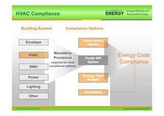
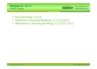
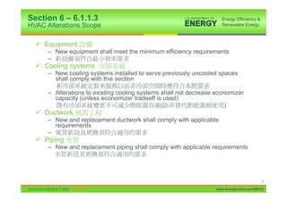
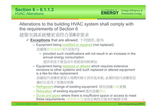
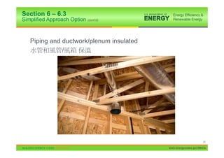
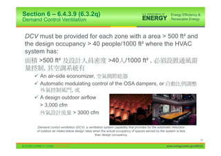
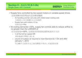
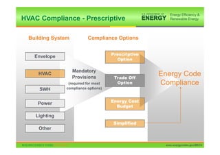
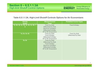
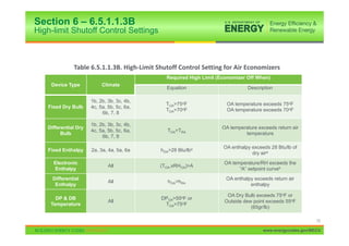
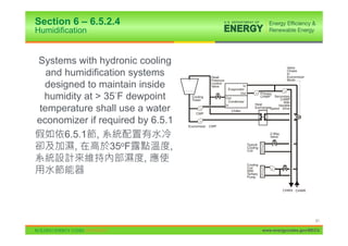
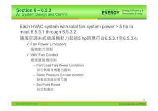
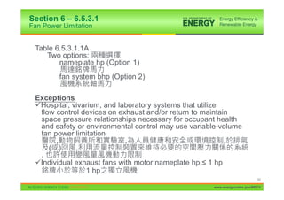
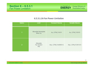
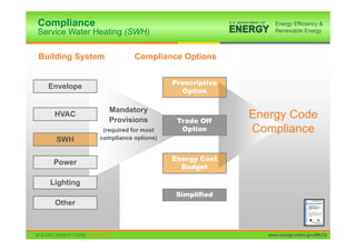
BUILDING ENERGY CODES UNIVERSITY SIMPLIFIED HVAC PATH
1. BUILDING ENERGY CODES UNIVERSITY
ANSI/ASHRAE/IES
Standard 90.1-2010 HVAC
Erik chiang
1
April 2011 – PNNL-SA-80143
www.energycodes.gov/BECU
2. HVAC Compliance
Building System Compliance Options
Prescriptive
Envelope
Option
Mandatory
HVAC
Provisions Trade Off
Energy Code
(required for most Option Compliance
SWH compliance options)
Energy Cost
Power
Budget
Lighting
Simplified
Other
2
www.energycodes.gov/BECU
3. Section 6 – 6.1.1
HVAC Scope
9 New Buildings
9 Additions to Existing Buildings
9 Alterations in Existing Buildings
3
www.energycodes.gov/BECU
4. Section 6 – 6.1.1.3
HVAC Alterations Scope
9 Equipment
– New equipment shall meet the minimum efficiency requirements
–
9 Cooling systems
– New cooling systems installed to serve previously uncooled spaces
shall comply with this section
– Alterations to existing cooling systems shall not decrease economizer
capacity (unless economizer tradeoff is used)
( )
9 Ductwork
– New and replacement ductwork shall comply with applicable
requirements
–
9 Piping
– New and replacement piping shall comply with applicable requirements
4
www.energycodes.gov/BECU
5. Section 6 – 6.1.1.3
HVAC Alterations
Alterations to the building HVAC system shall comply with
the requirements of Section 6
6
9 Exceptions that are allowed: ,
– Equipment being modified or repaired (not replaced)
( )
• provided such modifications will not result in an increase in the
annual energy consumption
– Equipment being replaced or altered which requires extensive
revisions to other systems and such replaced or altered equipment
is a like-for-like replacement
,
– Refrigerant change of existing equipment
– Relocation of existing equipment
– Ducts and pipes where there is insufficient space or access to meet
these requirements 5
www.energycodes.gov/BECU
6. Section 6 – 6.2
HVAC Compliance Paths
9 You have to follow Sections
– 6.1 General,
– 6.7 Submittals, and
– 6.8 Minimum Equipment Efficiency
9 And then you can follow either
– Section 6.3 Simplified Approach OR
6.3 ,
– Sections 6.4 Mandatory Provisions and 6.5 Prescriptive Path
6.4 6.5
9 Alternatively, you can follow Section 11 (ECB), in which
case Section 6.4 is mandatory
, 11 ( ), 6.4
6
www.energycodes.gov/BECU
7. Section 6 – 6.3
Simplified Approach Option
The simplified approach is an optional path for compliance
when the following are met:
,
9 Buildings with 1 or 2 stories 1 2
9 Buildings with gross floor area < 25,000 ft2
< 25,000 ft2
9 System serving single HVAC zone
9 Unitary packaged or split air
conditioners (air-cooled or
evaporatily cooled)
(
)
7
www.energycodes.gov/BECU
8. Section 6 – 6.3
Simplified Approach Criteria
a. Single HVAC zone
b. Single zone VAV controls (6.4.3.10) VAV
c. Cooling equipment efficiency (6.8.1)
d. Air economizers (6.5.1)
e. Heating equipment efficiency (6.8.1)
f. Exhaust air energy recovery (6.5.6.1)
g. Dual set point thermostat or manual changeover
h. Heat pump auxiliary heat control
i. No reheat or simultaneous cooling and heating for humidity control
j. Off-hour shutoff and temperature setback/setup
setback/setup
k. Piping insulation (Tables 6.8.3A and 6.8.3B)
l. Ductwork insulation and sealing (6.4.4.2.1)
m. Air balancing of ducted system
n. Outdoor air intake and exhaust systems (6.4.3.4)
o. Zone thermostatic controls to prevent simultaneous heating and cooling
p. Optimum start controls
q. Demand control ventilation (6.4.3.9)
8
www.energycodes.gov/BECU
9. Section 6 – 6.4.3.10 (6.3.2b)
Single Zone VAV Controls
9 Supply fans controlled by two-speed motors or variable-speed drives
– Air-handling and fan coil units with chilled-water cooling coils
– Supply fans with motors • 5 hp
>=5hp
9 At cooling demands ” 50%, supply fan controls able to reduce airflow to
no greater than the LARGER of
<=50%,
– ½ of the full fan speed OR
1/2 ,
– volume of outdoor air required to meet Standard 62.1 On and after
January 1, 2012
62.1 2012.1.1 ,
9
www.energycodes.gov/BECU
10. Section 6 – 6.4.3.10 (6.3.2b)
Single Zone VAV Controls
9 Supply fans controlled by two-speed motors or variable speed drives
– all AC equipment and air-handling units with direct expansion cooling and
cooling capacity at AHRI conditions • 110,000 Btu/h serving single zones
AHRI
>=110,000Btu/h
9 At control demands
– 2/3 of the full fan speed OR
2/3
– volume of outdoor air required to meet Standard 62.1
62.1
10
www.energycodes.gov/BECU
11. Section 6 – 6.4.3.10 (6.3.2b)
Single Zone VAV Controls (cont’d)
11
www.energycodes.gov/BECU
13. Section 6 – 6.3.2
Economizers
The system shall have an economizer, unless the economizer
Trade-off Option is used
,
9 Limited to unitary systems
9 Requires higher minimum cooling efficiency (EER)
(EER)
9 Trade-off EER by EER
– System size
– Climate zone
13
www.energycodes.gov/BECU
14. Section 6 – 6.3.2
Economizers
Reference Table 6.3.2 on page 40 in 90.1-2010
14
www.energycodes.gov/BECU
15. Section 6 – 6.5.1 (6.3.2d)
Economizers (cont’d)
9 Climate and size dependent (Tables 6.5.1A and B)
( 6.5.1A B)
9 There are LOTS of exception
9 Can use air economizers
– 100% of design supply air 100%
– Sequenced with mechanical cooling equipment
– High limit shutoff
– Dampers
15
www.energycodes.gov/BECU
16. Section 6 – 6.5.1 (6.3.2d)
Economizer Exceptions
Exceptions
9 Systems with gas phase air cleaning per Standard 62.1
62.1
9 Where >75% of the air must be humidified >35 Fdp
75% >35 Fdp
9 Systems with condenser heat recovery per 6.5.6.2.2a or
6.5.6.2.2b 6.5.6.2.2a 6.5.6.2.2b
9 Residential systems <5X limits in Table 6.5.1A <
6.5.1A 5
9 Systems with a balance point <=60 F <= 60 F
9 Systems expected to operate < 20hrs/wk 20hr
9 Systems serving zones with refrigerated casework
16
www.energycodes.gov/BECU
17. Section 6 – 6.5.1 (6.3.2d)
Economizer Exceptions (cont’d)
Exceptions
9 Where comfort cooling efficiency meets or exceeds Table 6.3.2
6.3.2
9 Systems serving computer rooms under certain conditions
,
17
www.energycodes.gov/BECU
18. Section 6 – 6.3
Simplified Approach Option (cont’d)
9 Manual changeover or dual set-point thermostat
9 Heat pump supplementary control
9 No reheat or simultaneous heating and cooling for
humidity control
9 Time clocks (except hotel/motel guest rooms and
systems requiring continuous operation)
( / )
18
www.energycodes.gov/BECU
19. Section 6 – 6.3
Simplified Approach Option (cont’d)
9 Balancing of ducted systems
9 Outdoor air intake and exhaust systems
9 Interlocked thermostats for separate heating and cooling
9 System > 10,000 cfm:
> 10,000 cfm
– optimum start controls
–
9 Demand control ventilation
19
www.energycodes.gov/BECU
21. Section 6 – 6.8.2B
Duct Insulation
Reference Tables 6.8.2A and B on page 68 in 90.1-2010
21
www.energycodes.gov/BECU
22. Section 6 – 6.4.4.1.3 (6.3.2k)
Piping Insulation
Tables 6.8.3A and 6.8.3B
Exceptions
9 Factory-installed
9 Piping conveying fluids
– design operating temperature range between 60 F-105 F, inclusive
60 F-105 F ,
– that haven’t been heated or cooled through the use of fossil fuels or
electricity or where heat gain or heat loss will not increase energy
usage
,
9 Hot water piping between shut off valve and coil, not > 4 ft in length,
when located in conditioned spaces
, 4ft
9 Piping ” 1 in. <= 1 in.
– No insulation required for strainers, control values, and balancing
values
, ,
22
www.energycodes.gov/BECU
23. Section 6 – 6.8.3
Piping Insulation
Reference Tables 6.8.3A and B on page 69 in 90.1-2010
23
www.energycodes.gov/BECU
24. Section 6 – 6.5.6.1 (6.3.2f)
Exhaust Air Energy Recovery
Required if:
9 Supply air capacity • value listed in Table 6.5.6.1
>= 6.5.6.1
– Values are based on climate zone and % of outdoor air flow rate at
design conditions
Recovery system effectiveness • 50%
>= 50%
24
www.energycodes.gov/BECU
25. Section 6 – 6.5.6.1 (6.3.2f)
Exhaust Air Energy Recovery Exceptions
9 Lab systems meeting 6.5.7.2
6.5.7.2
9 Systems serving uncooled spaces that are heated to < 60 F
< 60 F
9 Systems exhausting toxic, flammable, paint or corrosive fumes
or dust
, ,
9 Commercial kitchen hoods used for collecting grease or smoke
9 Where > 60% of outdoor heating energy is provided from site-
recovered or site solar energy
> 60%,
9 Heating energy recovery in climate zones 1 and 2
1 2
9 Cooling energy recovery in climate zones 3c, 4c, 5b, 5c, 6b, 7,
and 8
3c, 4c, 5b, 5c, 6b, 7 8
25
www.energycodes.gov/BECU
26. Section 6 – 6.5.6.1 (6.3.2f)
Exhaust Air Energy Recovery Exceptions
9 Where largest exhaust source is < 75% of the design outdoor
airflow
< 75%
9 Systems requiring dehumidification that employ energy
recovery in series with the cooling coil
,
9 Systems operating < 20 hrs/week at outdoor air % in Table
6.5.6.1
6.5.6.1 , 20hr,
26
www.energycodes.gov/BECU
27. Section 6 – 6.8.2B (6.3.2l)
Duct & Plenum Insulation
Reference Table 6.8.2B on page 68 in 90.1-2010
27
www.energycodes.gov/BECU
28. Section 6 – 6.4.3.9 (6.3.2q)
Demand Control Ventilation
DCV must be provided for each zone with a area > 500 ft² and
the design occupancy > 40 people/1000 ft² where the HVAC
system has:
>500 ft² >40 /1000 ft² ,
,
9 An air-side economizer,
9 Automatic modulating control of the OSA dampers, or
,
9 A design outdoor airflow
> 3,000 cfm
> 3000 cfm
Demand control ventilation (DCV): a ventilation system capability that provides for the automatic reduction
of outdoor air intake below design rates when the actual occupancy of spaces served by the system is less
than design occupancy.
28
www.energycodes.gov/BECU
29. HVAC Compliance
Building System Compliance Options
Prescriptive
Envelope
Option
Mandatory
HVAC
Provisions Trade Off
Energy Code
(required for most Option Compliance
SWH compliance options)
Energy Cost
Power
Budget
Lighting
Simplified
Other
29
www.energycodes.gov/BECU
33. Section 6 – 6.4.1.4
Verification of Equipment Efficiencies
Equipment efficiency information from manufacturers verified as
follows
,
9 EPACT equipment – to comply with DOE certification requirements
(EPACT) – (DOE)
9 If certification program exists for covered product and includes provisions
for verification and challenge of equipment efficiency ratings, product listed
in program OR
,
, ,
9 If product not listed in program, ratings verified by an independent
laboratory test report OR
,
,
33
www.energycodes.gov/BECU
34. Section 6 – 6.4.1.4
Verification of Equipment Efficiencies (cont’d)
9 If no certification program exists, equipment efficiency ratings
supported by data furnished by manufacturer OR
,
,
9 Where components from different manufacturers are used, system
designer specifies components whose combined efficiency meets
Section 6.4.1
,
6.4.1
9 Requirements for plate type liquid-to-liquid heat exchangers listed
in Table 6.8.1H
- , 6.8.1H
34
www.energycodes.gov/BECU
35. Section 6 – 6.4.1.5
Labeling
Mechanical equipment (6.4.1.5.1) – equipment not
covered by NAECA to have a permanent label stating
equipment complies with 90.1
(6.4.1.5.1) – NAECA
90.1
( NAECA )
35
www.energycodes.gov/BECU
36. Section 6 – 6.4.1.5
Labeling
Packaged terminal air conditioners (6.4.1.5.2) –
packaged terminal air conditioners and heat pumps
with sleeve sizes < 16 in. high and 42 in. wide with a
cross-sectional area < 670 in2 to be factory labeled as
follows:
(6.4.1.5.2) –
16 42 670 ,
:
9 Manufactured for nonstandard size applications only: not to be
installed in new construction projects
:
36
www.energycodes.gov/BECU
37. Section 6 – 6.4.2.1
Load Calculations
Must calculate heating and
cooling system design loads
Must determine calculations with
ANSI/ASHRAE/ACCA Standard
183-2007
ASHRAE Std. 183
37
www.energycodes.gov/BECU
38. Section 6 – 6.4.2.2
Pump Head
• When sizing pumps, head to be determined in
accordance with generally accepted engineering
standards/handbooks
• Method must be approved by the authority having
jurisdiction
• Must calculate the pressure drop through each device
and pipe segment in the critical circuit at design
conditions
• ,
38
www.energycodes.gov/BECU
39. Section 6 – 6.4.3.1
Controls – Zone Thermostatic & Dead Band
Required for each zone
9 Perimeter can be treated differently
Dead band controls
9 Thermostats must have at least a 5 F dead band
5F
9 Exceptions
– Thermostats that require manual changeover between heating and
cooling modes
– Special occupancy or applications where wide temperature ranges
aren’t acceptable (e.g., retirement homes) and approved by
adopting authority
, ( ; )
39
www.energycodes.gov/BECU
40. Section 6 – 6.4.3.2
Controls – Setpoint Overlap Restriction
If limit switches, mechanical stops, or software
programming for DDC systems are used
, , DDC
9 means will be provided to prevent the heating setpoint from
exceeding the cooling setpoint minus any applicable proportional
band
40
www.energycodes.gov/BECU
41. Section 6 – 6.4.3.3
Controls – Off-Hour
Temperature Control off-hour requirements
9 Automatic shutdown
9 Setback controls
9 Optimum start
9 Zone isolation
9 Exceptions, HVAC systems
,
– with heating/cooling capacity < 15,000 Btu/h
– / < 15,000 Btu/h
– intended to operate continuously
–
41
www.energycodes.gov/BECU
42. Section 6 – 6.4.3.3.1
Controls - Automatic Shutdown
Automatic 7-day/week time clock with 10-hour battery backup
10
9 Exception: 2-day/week thermostat for residential applications
: ,
Each control to have
9 Occupant sensor, OR ,
9 Manually-operated timer with maximum two hour duration, OR
, ,
9 Security system interlock
Exception
9 Residential occupancies allowed to operate with only 2 different
time schedules/wk
42
www.energycodes.gov/BECU
43. Section 6 – 6.4.3.3.2
Controls - Setback
Climate Zones 2-8
9 Lower heating setpoint to 55ºF or less
55ºF
Climate Zones 1b, 2b, 3b (hot/dry)
9 Automatically restart, temporarily operate
,
– Raise cooling setpoint to 90ºF or higher OR
90ºF
– Prevent high space humidity levels
43
www.energycodes.gov/BECU
44. Section 6 – 6.4.3.3.3
Controls - Optimum Start
Individual heating and cooling air distribution
systems with
,
9 Total design supply air capacity > 10,000 cfm
> 10,000 cfm
9 Served by one or more supply fans
Control algorithm to at least be a function of
9 Difference between space temperature and
occupied setpoint and amount of time prior to
scheduled occupancy
,
44
www.energycodes.gov/BECU
45. Section 6 – 6.4.3.3.4
Controls - Zone Isolation
Applies to
9 Each floor in a multistory building
9 Maximum 25,000 ft2 zone on one floor
25,000ft2
Requirements
9 Isolation devices to shut off outdoor and exhaust airflow when >
5,000 cfm >5,000cfm ,
9 Central systems shall be capable of stable operation with one
isolation zone
9 Capable of separate time schedules for each isolation zone
Figure 6-E
Isolation Methods for a Central VAV System
(User’s Manual – 90.1.-2007)
45
www.energycodes.gov/BECU
46. Section 6 – 6.4.3.4
Controls – Ventilation System
Stair and Shaft Vent dampers (6.4.3.4.1)
9Automatically closed during normal building operation
9Interlocked to open as required by fire and smoke detection systems
Shutoff Damper Controls (6.4.3.4.2)
9 All outdoor air intake and exhaust systems require motorized damper
9 Ventilation outdoor air and exhaust/relief dampers capable of automatically
shutting off during
/ ,
– Preoccupancy building warm-up, cool down, and setback
,
(Except when ventilation reduces energy costs or when ventilation must be
supplied due to code requirements)
( , .)
46
www.energycodes.gov/BECU
47. Section 6 – 6.4.3.4
Controls – Ventilation System (cont’d)
9Exceptions:
9 Backdraft gravity dampers okay
(BDD)
– For exhaust and relief in buildings < 3 stories in height above grade
3
– Of any height in climate zones 1 – 3
1, 2, 3
9 Ventilation systems serving unconditioned spaces
– 300 CFM
47
www.energycodes.gov/BECU
48. Section 6 – 6.4.3.4.3
Controls - Damper Leakage
Table 6.4.3.4.3 provides maximum leakage rates for
outdoor air supply and exhaust dampers
Table 6.4.3.4.3
Where OA supply and exhaust air dampers are required by
Section 6.4.3.4
6.4.3.4
9 They shall have a maximum leakage rate when tested in
accordance with AMCA Standard 500 as indicated in Table
6.4.3.4.3
AMCA
Standard 500,
Table 6.4.3.4.3.
48
www.energycodes.gov/BECU
49. Section 6 – 6.4.3.4.3
Controls - Damper Leakage
Table 6.4.3.4.3. Maximum Damper Leakage, cfm per ft2 at 1.0 in. w.g.
Ventilation Air Intake Exhaust / Reflief
Climate Zones Non-motorized1 Motorized Non-motorized1 Motorized
1, 2 - - - -
any heigh 20 4 20 4
3 - - - -
any heigh 20 10 20 10
4,5b,5c - - - -
< 3 stories not allowed 10 20 10
>=3 stories not allowed 10 not allowed 10
5a,6,7,8 - - - -
< 3 stories not allowed 4 20 4
>=3 stories not allowed 4 not allowed 4
49
www.energycodes.gov/BECU
50. Section 6 – 6.4.3.4.4
Ventilation Fan Controls
Fans with motors > 0.75 hp shall have automatic controls
complying with Section 6.4.3.3.1 that are capable of
shutting off fans when not required
0.75 hp , 6.4.3.3.1 ,
,
Exception
9 HVAC systems intended to operate continuously
50
www.energycodes.gov/BECU
51. Section 6 – 6.4.3.4.5
Enclosed Parking Garage Ventilation
Ventilation systems in enclosed parking garages
9automatically detect contaminant levels and stage fans or
9modulate fan airflow rates to ” 50%, provided acceptable
contaminant levels are maintained
50%
Exception
9 Garages < 30,000 ft2 with ventilation systems that don’t use
mechanical cooling or heating
30,000 ft2
9 Garages with a garage area to ventilation system motor nameplate
hp ratio > 1500 ft2/hp and don’t use mechanical cooling or heating
1500 ft2/hp,
9 Where permitted by AHJ
51
www.energycodes.gov/BECU
52. Section 6 – 6.4.3.5
Heat Pump Auxiliary Heat Control
Controls to prevent supplementary heat when heat pump
can handle the load
,
Exception
9Heat pumps
– With minimum efficiency regulated by NAECA
(NAECA)
– With HSPF rating meeting Table 6.8.1B (Includes all usage of
internal electric resistance heating)
Table 6.8.1B ( )
52
www.energycodes.gov/BECU
53. Section 6 – 6.4.3.6
Controls - Humidifier Preheat
Automatic valve to shut off preheat when humidification isn’t required
,
53
www.energycodes.gov/BECU
54. Section 6 – 6.4.3.7
Controls - Humidification and Dehumidification
Provide means to prevent simultaneous
operation of humidification and
dehumidification equipment
9 Limit switches, mechanical stops, or
software programming (DDC systems)
Exceptions
9 Zones served by desiccant systems, used
with direct evaporative cooling in series
9 Systems serving zones where specific
humidity levels are required and approved
by jurisdiction
– Museums and hospitals
,
54
www.energycodes.gov/BECU
55. Section 6 – 6.4.3.8
Controls - Freeze Protection and Snow/Ice
Automatic controls for
,
9 Freeze protection systems
– outside air temperatures > 40 F or when conditions of protected
fluid will prevent freezing
40oF
9 Snow- and ice-melting systems
– pavement temperature > 50 F and no precipitation is falling and
outdoor temperature > 40 F
50oF 40oF
55
www.energycodes.gov/BECU
56. Section 6 – 6.4.3.9 (6.3.2q)
Demand Control Ventilation
DCV must be provided for each zone with a area > 500 ft² and
the design occupancy > 40 people/1000 ft² where the HVAC
system has:
>500 ft² >40 /1000 ft² ,
,
9 An air-side economizer,
9 Automatic modulating control of the OSA dampers, or
,
9 A design outdoor airflow
> 3,000 cfm
> 3000 cfm
Demand control ventilation (DCV): a ventilation system capability that provides for the automatic reduction
of outdoor air intake below design rates when the actual occupancy of spaces served by the system is less
than design occupancy.
56
www.energycodes.gov/BECU
57. Section 6 – 6.4.3.9
Demand Control Ventilation (cont’d)
Exceptions :
9 System with energy recovery complying with 6.5.6.1
6.5.6.1
9 Multiple-zone systems without DDC of individual zones
communicating with a central control panel
DDC
9 Systems with a design outdoor airflow less than 1200 cfm
1200cfm
9 Spaces where the supply airflow rate minus any makeup or
outgoing transfer air requirement is less than 1200 cfm
1200cfm
57
www.energycodes.gov/BECU
58. Section 6 – 6.4.3.10 (6.3.2b)
Single Zone VAV Controls
9 Supply fans controlled by two-speed motors or variable-speed drives
– Air-handling and fan coil units with chilled-water cooling coils
– Supply fans with motors • 5 hp
>=5hp
9 At cooling demands ” 50%, supply fan controls able to reduce airflow to
no greater than the LARGER of
<=50%,
– ½ of the full fan speed OR
1/2 ,
– volume of outdoor air required to meet Standard 62.1 On and after
January 1, 2012
62.1 2012.1.1 ,
58
www.energycodes.gov/BECU
59. Section 6 – 6.4.3.10 (6.3.2b)
Single Zone VAV Controls
9 Supply fans controlled by two-speed motors or variable speed drives
– all AC equipment and air-handling units with direct expansion cooling and
cooling capacity at AHRI conditions • 110,000 Btu/h serving single zones
AHRI
>=110,000Btu/h
9 At control demands
– 2/3 of the full fan speed OR
2/3
– volume of outdoor air required to meet Standard 62.1
62.1
59
www.energycodes.gov/BECU
60. Section 6 – 6.4.3.10 (6.3.2b)
Single Zone VAV Controls (cont’d)
60
www.energycodes.gov/BECU
61. Section 6 – 6.4.4
HVAC System Construction and Insulation
9 Insulation installed in accordance with industry-accepted standards
9 Insulation protection
9 Duct and plenum insulation
9 Piping insulation
9 Sensible heating panel insulation
9 Radiant floor heating
9 Duct sealing
9 Duct leakage tests
61
www.energycodes.gov/BECU
62. Section 6 – 6.4.4.1.1
General
Insulation installed in accordance with industry-accepted standards
Insulation
9 Protected from damage due to sunlight, moisture, equipment
maintenance, and wind
, ,
9 Exposed to weather to be suitable for outdoor service
,
9 Covering chilled water piping, refrigerant suction piping, or cooling ducts
located outside the conditioned space to include a vapor retardant
located outside the insulation, all penetrations and joints of which to be
sealed
, ,
,
62
www.energycodes.gov/BECU
63. Section 6 – 6.4.4.1.2
Duct and Plenum Insulation
All supply and return ducts and plenums to be insulated per Tables 6.8.2A
and 6.8.2B
, 6.8.2A 6.8.2B
Exceptions
9 Factory-installed plenums, casings, or ductwork furnished as part of HVAC
equipment
, ,
9 Ducts located in heated, semiheated, or cooled spaces
,
9 For runouts < 10 ft in length to air terminals or air outlets, the R-value need
not exceed R-3.5
10 ft, R-3.5
9 Backs of air outlets and outlet plenums exposed to unconditioned or indirectly
conditioned spaces with face areas > 5 ft2 need not exceed R-2; those ” 5 ft2
need not be insulated
5 ft2
R-2; ( ) 5 ft2
63
www.energycodes.gov/BECU
64. Section 6 – 6.4.4.1.3 (6.3.2k)
Piping Insulation
Tables 6.8.3A and 6.8.3B
Exceptions
9 Factory-installed
9 Piping conveying fluids
– design operating temperature range between 60 F-105 F, inclusive
60 F-105 F ,
– that haven’t been heated or cooled through the use of fossil fuels or
electricity or where heat gain or heat loss will not increase energy
usage
,
9 Hot water piping between shut off valve and coil, not > 4 ft in length,
when located in conditioned spaces
, 4ft
9 Piping ” 1 in. <= 1 in.
– No insulation required for strainers, control values, and balancing
values
, ,
64
www.energycodes.gov/BECU
65. Section 6 – 6.4.4.2.1
Duct Sealing
Ductwork and all plenums with
pressure class ratings shall be
constructed to
,
9 seal class A, as required to
meet the requirements of
6.4.4.2.2
class A ,
6.4.4.2.2
9 standard industry practice
65
www.energycodes.gov/BECU
66. Section 6 – 6.4.4.2.2
Duct Leakage Tests
Designed > 3 in. w.c. and all ductwork
located outdoors
3 in.
9 Leak tested
9 Representative sections • 25% of
the total installed duct area shall
be tested
25%( )
9 Ratings > 3 in. w.c. to be
identified on drawings
3 in.,
9 Maximum permitted duct leakage
– Lmax = CLP0.65
• Where Lmax = maximum
permitted leakage in
cfm/100 ft2 duct surface
area
• CL = 6 cfm/100ft2 duct
surface area at 1 in. wc
• P = test pressure in. wc. 66
www.energycodes.gov/BECU
67. HVAC Compliance - Prescriptive
Building System Compliance Options
Prescriptive
Envelope
Option
Mandatory
HVAC
Provisions Trade Off
Energy Code
(required for most Option Compliance
SWH compliance options)
Energy Cost
Power
Budget
Lighting
Simplified
Other
67
www.energycodes.gov/BECU
68. Section 6 – 6.5
HVAC Prescriptive Path
9 Economizers (Section 6.5.1)
9 Simultaneous Heating and Cooling Limitation (Section 6.5.2)
9 Air System Design and Control (Section 6.5.3)
9 Hydronic System Design and Control (Section 6.5.4)
9 Heat Rejection Equipment (Section 6.5.5)
9 Energy Recovery (Section 6.5.6)
9 Exhaust Systems (Section 6.5.7)
9 Radiant Heating Systems (Section 6.5.8)
9 Hot Gas Bypass Limitation (Section 6.5.9)
68
www.energycodes.gov/BECU
69. Section 6 – 6.5.1.1.2
Control Signal
Dampers capable of being sequenced with the mechanical
cooling equipment and shall not be controlled by only
mixed air temperature
,
Exception
9 Systems controlled from space temperature (such as single-
zone systems)
( )
69
www.energycodes.gov/BECU
70. Section 6 – 6.5.1.1.3
High Limit Shutoff
9 Automatically reduce outdoor air intake to minimum
outdoor air quantity when outdoor air intake will no
longer reduce cooling energy usage
,
9 Control types for specific climates from Table 6.5.1.1.3A
6.5.1.1.3A. ,
9 Settings from Table 6.5.1.1.3B
70
www.energycodes.gov/BECU
71. Section 6 – 6.5.1.1.3A
High-limit Shutoff Control Options
Table 6.5.1.1.3A. High-Limit Shutoff Controls Options for Air Economizers
Climate Allowed Control Prohibited Control Types
Zones Types
1b, 2b, 3b, 3c, 4b, 4c, 5b, 5c, 6b, 7, Fixed Dry Bulb Fixed Enthalpy
8 Differential Dry Bulb
Electronic Enthalpya
Differential Enthalpy
DP & DB Temperature
1a, 2a, 3a, 4a Fixed Dry Bulb Fixed Dry Bulb
Fixed Enthalpy Differential Dry Bulb
Differential Enthalpy
DP & DB Temperature
5a, 6a Fixed Dry Bulb
Differential Dry Bulb
Fixed Enthalpy
Electronic Enthalpya
Differential Enthalpy
DP & DB Temperature
71
www.energycodes.gov/BECU
72. Section 6 – 6.5.1.1.3B
High-limit Shutoff Control Settings
Table 6.5.1.1.3B. High Limit Shutoff Control Setting for Air Economizers
Required High Limit (Economizer Off When)
Device Type Climate
Equation Description
1b, 2b, 3b, 3c, 4b,
TOA>75oF OA temperature exceeds 75oF
Fixed Dry Bulb 4c, 5a, 5b, 5c, 6a,
TOA>70oF OA temperature exceeds 70oF
6b, 7, 8
1b, 2b, 3b, 3c, 4b,
Differential Dry OA temperature exceeds return air
4c, 5a, 5b, 5c, 6a, TOA>TRA
Bulb temperature
6b, 7, 8
OA enthalpy exceeds 28 Btu/lb of
Fixed Enthalpy 2a, 3a, 4a, 5a, 6a hOA>28 Btu/lba
dry aira
Electronic OA temperature/RH exceeds the
All (TOA,xRHOA)>A
Enthalpy “A” setpoint curveb
Differential OA enthalpy exceeds return air
All hOA>hRA
Enthalpy enthalpy
OA Dry Bulb exceeds 75oF or
DP & DB DPOA>55oF or
All Outside dew point exceeds 55oF
Temperature TOA>75oF
(65gr/lb)
72
www.energycodes.gov/BECU
73. Section 6 – 6.5.1.1.4
Dampers
Return, exhaust/relief and outdoor air dampers to meet the
requirements in 6.4.3
, / , 6.4.3
73
www.energycodes.gov/BECU
74. Section 6 – 6.5.1.1.5
Relief of Excess Outdoor Air
Means to relieve excess outdoor air during economizer
operation to prevent overpressurizing the building
Outlet located to avoid recirculation into the building
74
www.energycodes.gov/BECU
75. Section 6 – 6.5.1.2.1
Design Capacity – Water Economizers
System capable of cooling supply air by indirect evaporation and
providing up to 100% of expected system cooling load at outside air
temperatures of 50 F dry bulb/45 F wet bulb and below
50oF/ 45oF
, 100%
Exception
9 Systems primarily serving computer rooms
– Where 100% of expected system cooling load at 40 F dry bulb/35 F wet
bulb is met with evaporative water economizers
, 40oF DB/35oF WB 100%
– With dry cooler water economizers that satisfy 100% of expected system
cooling load at 35 F dry bulb
, 35oF DB 100%
9 Dehumidification requirements that your design can meet 100% of
expected cooling load at 45 F dry bulb/40 F wet bulb with evaporative
water economizers
, 45oF DB/40oF WB 100%
.
75
www.energycodes.gov/BECU
76. Section 6 – 6.5.1.2.2
Maximum Pressure Drop - Water Economizers
Precooling coils and water-to- Valve
Closes
In
Head Economizer
water heat exchangers to Pressure
Control
Valve In
Mode
Evaporator
have either Cooling
Tower
Out
Out Primary
CHWP Secondary
CHWP
Condenser With
In Heat Variable
ExchangerSpeed Drive
Chiller
CWP
Economizer CWP
9 Water-side pressure drop of 2-Way
Valve
< 15 ft of water OR Typical
Cooling
Coil
Cooling
9 Bypassed when not in use
Coil
With
Tertiary
Pump
,
CHWS CHWR
Figure 6-O from
90.1 User’s Manual
76
www.energycodes.gov/BECU
77. Section 6 – 6.5.1.3
Integrated Economizer Control
Economizers must be integrated with mechanical cooling
systems and be capable of providing partial cooling even
when additional mechanical cooling is required
,
77
www.energycodes.gov/BECU
78. Section 6 – 6.5.1.4
Economizer Heating System Impact
Designed so economizer
operation doesn’t increase the
building heating energy use during
normal operation
,
Exception
9 Economizers on VAV systems that
cause zone level heating to
increase due to a reduction in
supply air temperature
(VAV) ,
,
78
www.energycodes.gov/BECU
79. Section 6 – 6.5.2.1
Zone Thermostatic Controls
Capable of operating in sequence the supply of heating and
cooling energy to the zone
Controls prevent
9 Reheating
9 Recooling
9 Mixing or simultaneously supplying air previously heated or
cooled
9 Other simultaneous operation of heating and cooling systems to
the same zone
79
www.energycodes.gov/BECU
80. Section 6 – 6.5.2.1
Zone Thermostatic Controls – Exceptions
Zones for which volume of air that is reheated, recooled, or
mixed is less than the larger of the following
,
9 30% of zone design peak supply
30%
9 Outside air flow rate to meet 6.2 of Standard 62.1 for the zone
ASHRAE Std. 62.1 6.2
9 Any higher rate that can be demonstrated to jurisdiction to reduce
overall system annual energy usage
9 Air flow rate required to meet applicable codes or accreditation
standards (pressure relationships or minimum air change rates)
( )
80
www.energycodes.gov/BECU
81. Section 6 – 6.5.2.1
Zone Thermostatic Controls – Exceptions (cont’d)
Zones that comply with all of these
9 Air flow rate in dead band that doesn’t exceed larger of these
,
• 20% of zone design peak supply
20%
• Outdoor air flow rate to meet 6.2 of Standard 62.1 for the zone
ASHRAE Std. 62.1 6.2
• Any higher rate that can be demonstrated to jurisdiction to reduce overall system annual energy
usage
9 Air flow rate that’s reheated, recooled, or mixed in peak heating demand < 50% of zone design
peak supply
, 50%
9 Air flow between dead band and full heating or full cooling to be modulated
9 Lab exhaust systems complying with 6.5.7.2
6.5.7.2
9 Zones where • 75% of energy for reheating or providing warm air in mixing systems is from
site-recovered or site-solar source
75%
81
www.energycodes.gov/BECU
82. Section 6 – 6.5.2.1.1
Supply Air Temperature Reheat Limit
Zones with both supply and return/exhaust air openings > 6
ft above floor to not supply heating air > 20 F above space
temperature
/ 6ft,
20oF
9Applies in other parts of the Standard where reheating is allowed
Exceptions
9Laboratory exhaust systems complying with 6.5.7.2
6.5.7.2
9During preoccupancy building warm-up and setback
82
www.energycodes.gov/BECU
83. Section 6 – 6.5.2.2
Hydronic System Controls
To prevent the simultaneous heating and cooling in
hydronic systems
83
www.energycodes.gov/BECU
84. Section 6 – 6.5.2.2.1
Three-Pipe System
No common return system for both hot and chilled water
84
www.energycodes.gov/BECU
85. Section 6 – 6.5.2.2.2
Two-Pipe Changeover System
85
Diagram Courtesy of Ken Baker
www.energycodes.gov/BECU
86. Section 6 – 6.5.2.2.2
Two-Pipe Changeover System (cont’d)
Two-pipe changeover system is allowed if it meets the following
requirements:
,
9 Dead band from one mode to another is • 15 F outdoor air
temperature
15oF
9 Controls to allow operation of • 4 hours in one mode before
changing to another mode
4
9 Reset controls so heating and cooling supply temperatures at
changeover point no more than 30 F apart
, 30oF
86
Diagram Courtesy of Ken Baker
www.energycodes.gov/BECU
87. Section 6 – 6.5.2.2.3
Hydronic (Water Loop) Heat Pump Systems
Diagram Courtesy of Ken Baker
87
www.energycodes.gov/BECU
88. Section 6 – 6.5.2.2.3
Hydronic (Water Loop) Heat Pump Systems (cont’d)
Controls to provide heat pump water supply temperature deadband of at
least 20 F between initiation of heat rejection and heat addition by central
devices
20oF
Cooling tower bypass or cooling tower isolation dampers
A two-position valve at each hydronic heat pump for hydronic systems
having a total pump system power > 10 hp
10hp ,
Exception
9 If system loop temperature optimization controller is used, deadband < 20 F is
allowed
88
www.energycodes.gov/BECU
89. Section 6 – 6.5.2.3
Dehumidification
Humidistatic controls to prevent
9 Reheating
9 Mixing of hot and cold air streams
9 Heating and cooling of same air stream
89
www.energycodes.gov/BECU
90. Section 6 – 6.5.2.3
Dehumidification Exceptions
9 Systems capable of reducing supply air flow to 50%, or to
minimum ventilation
50%,
9 Systems under 80,000 BTU/h that can unload at least 50%
80,000 Btu/h, 50%
9 Systems smaller than 40,000 BTU/h
40,000 Btu/h
9 Process applications (exception does NOT apply to
computer rooms)
( )
9 75% of reheat or re-cool energy is recovered or solar
75%
90
www.energycodes.gov/BECU
91. Section 6 – 6.5.2.4
Humidification
Systems with hydronic cooling
Valve
and humidification systems Head
Closes
In
Economizer
Pressure Mode
designed to maintain inside Control
Valve In
Evaporator
Out
humidity at > 35 F dewpoint Cooling
Tower
Out
Condenser
Primary
CHWP Secondary
CHWP
With
In Heat Variable
temperature shall use a water CWP
Chiller
ExchangerSpeed Drive
economizer if required by 6.5.1 Economizer CWP
6.5.1 , 2-Way
Valve
, 35oF , Typical
Cooling
Coil
, Cooling
Coil
With
Tertiary
Pump
CHWS CHWR
91
www.energycodes.gov/BECU
92. Section 6 – 6.5.3
Air System Design and Control
Each HVAC system with total fan system power > 5 hp to
meet 6.5.3.1 through 6.5.3.2
5 hp 6.5.3.1 6.5.3.4.
9 Fan Power Limitation
9 VAV Fan Control
– Part Load Fan Power Limitation
– Static Pressure Sensor location
– Set Point Reset
92
www.energycodes.gov/BECU
93. Section 6 – 6.5.3.1
Fan Power Limitation
Table 6.5.3.1.1A
Two options:
nameplate hp (Option 1)
fan system bhp (Option 2)
Exceptions
9Hospital, vivarium, and laboratory systems that utilize
flow control devices on exhaust and/or return to maintain
space pressure relationships necessary for occupant health
and safety or environmental control may use variable-volume
fan power limitation
, , ,
( ) ,
.
9Individual exhaust fans with motor nameplate hp ” 1 hp
1 hp
93
www.energycodes.gov/BECU
94. Section 6 – 6.5.3.1
Fan Power Limitation
6.5.3.1.1A Fan Power Limitation
Option Limit Constant Volume Variable Volume
Allowable Nameplate
1 hp CFMs*0.0011 hp CFMs*0.0015
Motor hp
Allowable
2 Fan System bhp CFMs*0.00094+A bhp CFMs*0.0013+A
bhp
94
www.energycodes.gov/BECU
95. Section 6 – 6.5.3.1
Fan Power Limitation
6.5.3.1.1B Fan Power Limitation Pressure Drop Adjustment
Device Adjustment
Credits
Fully ducted return and/or exhaust 0.5 in. w.c. (2.15 in. w.c. for laboratory and vivarium
air system systems)
Return and/or exhaust airflow 0.5 in. w.c.
control devices
Exhaust filters, scrubbers, or The pressure drop of device calculated at fan system
other exhaust treatment design condition
Particulate Filter Credit : 0.5 in. w.c.
MERV 9-12
Particulate Filter Credit : 0.9 in. w.c.
MERV 13-15
95
www.energycodes.gov/BECU
96. Section 6 – 6.5.3.1
Fan Power Limitation
6.5.3.1.1B Fan Power Limitation Pressure Drop Adjustment
Particulate Filter Credit : The pressure drop of device calculated at 2*
MERV 16 and greater clean filter pressure drop at fan system
and electronically enhanced filters design condition
Carbon and other gas-phase air cleaners Clean filter pressure drop at fan system design
condition
Biosafety cabinet Pressure drop of device at fan system design
condition
Energy Recovery Device, other than Coil (2.2 Energy Recovery Effectiveness)-0.5 in.
Runaround Loop w.c. for each airstream
Coil Runaround Loop 0.6 in. w.c. for each airstream
Evaporative humidifier/cooler in series with Pressure drop of device at fan system design
another cooling coil condition
Sound Attenuation Section 0.15 in. w.c.
Exhaust system serving fume hoods 0.35 in. w.c.
laboratory and vivarium exhaust systems in 0.25 in. w.c. / 100ft of vertical duct exceeding
high-rise building 75ft
96
www.energycodes.gov/BECU
97. Section 6 – 6.5.3.1.2
Motor Nameplate Horsepower
Selected fan motor to be no larger than first available motor size
greater than bhp
, (BHP)
Fan bhp on design documents
(BHP)
Exceptions
9 Fans < 6 bhp, where first available motor larger than bhp has
nameplate rating within 50% of bhp, next larger nameplate motor
size may be selected
6 bhp , (bhp) 50%
,
9 Fans • 6 bhp, where first available motor larger than bhp has
nameplate rating within 30% of bhp, next larger nameplate motor
size may be selected
6 bhp( ) , (bhp)
30% , 97
www.energycodes.gov/BECU
98. Section 6 – 6.5.3.2.1
Part-Load Fan Power Limitation
Individual VAV fans with motors • 10 hp
10 hp( ) (VAV)
9 Must have either:
– Variable Speed Drive
– Vane axial fan with variable-pitch fan blades
– Other controls and devices to result in fan motor demand ” 30% of
design wattage at 50% of design air volume when static pressure
set point = 1/3 of total design static pressure, based on
manufacturer’s certified fan data
– , 1/3 ,
50% ,
30%
98
www.energycodes.gov/BECU
99. Section 6 – 6.5.3.2.2
Static Pressure Sensor Location
Placed so controller set point is ” 1/3 the total design fan
static pressure
, 1/3
9 Except for digital control systems with zone reset capabilities
where it may be at the fan discharge
,
Install multiple sensors in each major branch if sensor
would be located downstream of a major duct split
,
99
www.energycodes.gov/BECU
100. Section 6 – 6.5.3.2.3
Setpoint Reset
For systems with direct digital control of individual zone
boxes reporting to the central control panel
9 Static pressure set point reset based on zone requiring the
most pressure
100
www.energycodes.gov/BECU
101. Section 6 – 6.5.3.3
Multiple-zone VAV System Ventilation Optimization
Control
In multiple-zone VAV systems with DDC of individual zone boxes
reporting to central control panel
DDC
9 Include means to automatically reduce outdoor air intake flow below
design rates in response to changes in system ventilation efficiency
as per Standard 62.1, Appendix A
( Std. 62.1 A ),
101
www.energycodes.gov/BECU
102. Section 6 – 6.5.3.3
Multiple-zone VAV System Ventilation Optimization
Control Exceptions
Exceptions
9 VAV systems with zonal transfer fans that recirculate air from other
zones without directly mixing it with outdoor air, dual-duct dual-fan
VAV systems, and VAV systems with fan-powered terminal units
,
, ,
.
9 Systems required to have exhaust air energy recovery complying
with 6.5.6.1
6.5.6.1
9 Systems where total design exhaust airflow is > 70% of total
outdoor air intake flow requirements
70%
102
www.energycodes.gov/BECU
103. Section 6 – 6.5.3.4
Supply-air Temperature Reset Controls
Multiple zone HVAC systems to have controls to automatically reset
supply-air temperature in response to building loads or outdoor air
temperature
, ,
Controls to be capable of resetting supply air temperature at least 25%
of difference between design supply-air temperature and design room
air temperature
25%
Controls that adjust the reset based on zone humidity are okay
Zones expected to experience relatively constant loads to be designed
for fully reset supply temperature
¸
103
www.energycodes.gov/BECU
104. Section 6 – 6.5.3.4
Supply-air Temperature Reset Controls Exceptions
Exceptions
9 Climate zones 1a, 2a, and 3a
1a, 2a, 3a
9 Systems that prevent reheating, recooling or mixing of heated and cooled
supply air
, ,
9 75% of energy for reheating is from site-recovered or site solar energy
sources
75%
104
www.energycodes.gov/BECU
105. Section 6 – 6.5.4
Hydronic System Design and Control
HVAC hydronic systems with total pump system power
> 10 hp to meet 6.5.4.1 – 6.5.4.4
10 hp , 6.5.4.1-6.5.4.4
9 Hydronic Variable Flow Systems
9 Pump Isolation
9 Chilled and Hot Water Temperature Reset
9 Hydronic (water-loop) Heat Pumps and Water-Cooled Unitary
Air-Conditioners
( )
9 Pipe Sizing
105
www.energycodes.gov/BECU
106. Section 6 – 6.5.4.1
Hydronic Variable Flow
HVAC pumping systems to include control valves
9 Designed to modulate or step open and close as a function of load
,
9 Designed for variable fluid flow
9 Capable of reducing flow rates to ” 50% of design flow rate
50%( )
Individual pumps serving variable flow systems with a motor > 5
hp
, 5 hp
9 Have controls and/or devices resulting in pump motor demand
” 30% of design wattage at 50% of design water flow
/ , 50% , 30%
106
www.energycodes.gov/BECU
107. Section 6 – 6.5.4.1
Hydronic Variable Flow (cont’d)
Differential pressure setpoint to be ” 110% of that required to
achieve design flow through the heat exchanger
110%
If differential pressure control and DDC controls are used
DDC
9 Reset setpoint downward based on valve positions until one valve
is nearly wide open
107
www.energycodes.gov/BECU
108. Section 6 – 6.5.4.1
Hydronic Variable Flow
Exceptions
9 Systems where
– Minimum flow is < minimum flow required by equipment
manufacturer for proper operation of equipment served
by the system
– Total pump system power ” 75 hp
75 hp( )
9 Systems that include ” 3 control valves
3
108
www.energycodes.gov/BECU
109. Section 6 – 6.5.4.2
Pump Isolation
If chilled water plant has more than one chiller or boiler
plant has more than one boiler
9 Provide for flow reduction when chiller or boiler is shut down
,
109
www.energycodes.gov/BECU
110. Section 6 – 6.5.4.3
Chilled and Hot Water Temperature Reset Controls
Affects systems with design capacity > 300,000 Btu/h
300,000 Btu/h ,
9 To include controls to automatically reset supply water
temperatures by representative building loads (including return
water temperature) or by outside air temperature
( )
Exceptions
9 If controls would result in improper operation
9 Hydronic systems with variable flow
110
www.energycodes.gov/BECU
111. Section 6 – 6.5.4.4
Hydronic Heat Pumps and Water-Cooled Unitary
Air-Conditioners
9 Two-position valves at each hydronic heat pump must be provided
and interlocked to shut off water flow to the heat pump when the
compressor is off
,
Exceptions
9 Units using water economizers
For hydronic heat pumps and water-cooled unitary ACs with total pump
power > 5 hp
5hp
9 Controls or devices must be provided to have pump motor demand ”
30% of design wattage at 50% of design water flow
/ , 50% , 30%
9 This basically converts the system into a variable flow system. As
such, these systems must also comply with 6.5.4.1
6.4.4.1
111
www.energycodes.gov/BECU
112. Section 6 – 6.5.4.5
Pipe Sizing
Chilled-water and condenser-water piping so design flow rate in
each segment doesn’t exceed values in Table 6.5.4.5.
, , 6.5.4.5
This table presents the maximum allowed flow rates per section of
pipe as a function of the following three criteria:
,
– Pipe size
– Annual hours of operation
– System flow and control
112
www.energycodes.gov/BECU
113. Section 6 – 6.5.4.5
Pipe Sizing Exceptions
Exceptions
9Rates exceeding the Table are allowed if the specific section of
pipe in question isn’t in the critical circuit > 30% of operating
hours
,
30%, 6.5.4.5
9Piping systems with equivalent or lower total pressure drop than
the same system with standard weight steel pipe with piping and
fittings sized per the Table
6.5.4.5 ,
113
www.energycodes.gov/BECU
114. Section 6 – 6.5.5
Heat Rejection Equipment
Applies to heat rejection equipment used in comfort cooling systems
such as
9 Air-cooled condensers
9 Open cooling towers
9 Closed-circuit cooling towers
9 Evaporative condensers
Exceptions
9 Heat rejection devices included as an integral part of equipment listed
devices whose energy usage is included in Tables 6.8.1A-6.8.1D
, Tables 6.8.1A 6.8.1D
114
www.energycodes.gov/BECU
115. Section 6 – 6.5.5.2
Fan Speed Control
Fan Speed Control
9 Each fan powered by a motor • 7.5 hp
7.5 hp( )
– Have capability to operate fan at ” 2/3 full speed
2/3
– Have controls to automatically change the fan speed to control the
leaving fluid temperature or condensing temperature/pressure of the
heat rejection device
115
www.energycodes.gov/BECU
116. Section 6 – 6.5.5.2
Fan Speed Control Exceptions
Exceptions
– Condenser fans serving multiple refrigerant circuits or flooded
condensers
– Installations in climates zones 1 and 2
1 2
– Up to 1/3 of the fans on a multiple fan application speed
controlled
1/3( ) ,
116
www.energycodes.gov/BECU
117. Section 6 – 6.5.5.3
Limitation on Centrifugal Fan Open-Circuit
Cooling Towers
• If towers have a combined rated capacity • 1100 gpm at 95 F
condenser water return, 85 F condenser water supply, and
75 F outdoor air wet-bulb temperature
, 1100gpm( ) , 95oF
85oF , 75oF
– Must meet requirement for axial fan open-circuit cooling towers
in Table 6.8.1G
6.8.1G
Exceptions
– Ducted (inlet or discharge)
( )
– Require external sound attenuation
117
www.energycodes.gov/BECU
118. Section 6 – 6.5.6.2
Heat Recovery for Service Water Heating
Condenser recovery required if
,
9 24 hrs per day and
24 ,
9 Heat rejection > 6,000,000 Btu/h and
6,000,000 Btu/h,
9 SWH load > 1,000,000 Btu/h
1,000,000 Btu/h
The required heat recovery system shall have the
capacity to provide the smaller of
9 60% of the peak heat rejection load at design conditions or
60%,
9 preheat of the peak service hot water draw to 85 F.
85 oF
118
www.energycodes.gov/BECU
119. Section 6 – 6.5.6.2
Heat Recovery for Service Water Heating Exceptions
Exceptions
9If condenser heat recovery is used for space heating with a heat
recover design > 30% of peak water-cooled condenser load at
design conditions
,
30%
9If 60% of service water heating is provided from site-solar or
site-recovered energy or other sources
60%
119
www.energycodes.gov/BECU
120. Section 6 – 6.5.7.1
Kitchen Exhaust Systems
• Replacement air introduced directly into hood cavity to be ”
10% of hood exhaust airflow rate
10%
• Conditioned supply air to not exceed the greater of
:
– Supply flow required to meet space heating or cooling load
– Hood exhaust flow minus available transfer air from adjacent
spaces
120
www.energycodes.gov/BECU
121. Section 6 – 6.5.7.1
Kitchen Exhaust Systems
• If kitchen/dining facility has total kitchen hood exhaust airflow
rate > 5,000 cfm, each hood’s exhaust rate must comply with
Table 6.5.7.1.3
/ 5000cfm ,
6.5.7.1.3
– If a single hood or hood section is over appliances with different
duty ratings, then the max. airflow rate for that can’t exceed the
Table values for highest appliance duty rating under that hood or
hood section
, ,
Exception
• If at least 75% of all replacement air is transfer air that would
otherwise be exhausted
75% , .
121
www.energycodes.gov/BECU
122. Section 6 – 6.5.7.1
Kitchen Exhaust Systems, con’t
9 Kitchens/dining facilities with total kitchen hood exhaust airflow rate
> 5,000 cfm must have one of these:
/ 5000cfm , :
– At least 50% of all replacement air is transfer air that would otherwise
be exhausted
50% , .
– Demand ventilation systems on at least 75% of exhaust air (capable of
at least 50% reduction in exhaust and replacement air system airflow
rates)
, 75% .
50%
– Listed energy recovery devices with sensible heat recover effectiveness
of not less than 40% on at least 50% of the total exhaust airflow
50% , 40%
122
www.energycodes.gov/BECU
123. Section 6 – 6.5.7.1
Kitchen Exhaust Systems, con’t
9 Performance testing must be done using an approved
field test method
9 If demand control ventilation systems are used, additional testing
is required
,
123
www.energycodes.gov/BECU
124. Section 6 – 6.5.7.2
Laboratory Exhaust Systems
9 Laboratory exhaust systems with total exhaust rate > 5,000
cfm to have one of the following
5,000 cfm , :
9 VAV lab exhaust and room supply system capable of reducing
exhaust and makeup air flow rates and/or incorporate a heat
recovery system
, /
9 VAV lab exhaust and room supply systems required to have
minimum circulation rates to comply with code to be capable of
reducing zone exhaust and makeup air flow rates to the regulated
minimum circulation values or minimum required to maintain
pressurization relationship requirements
,
, ,
9 Non-regulated zones capable of reducing exhaust and makeup air flow
rates to 50% of zone design values or minimum required to maintain
pressurization relationship requirements
, 50% ,
124
www.energycodes.gov/BECU
125. Section 6 – 6.5.7.2
Laboratory Exhaust Systems (Cont’d)
9 Direct makeup air supply to equal at least 75% of exhaust air flow
rate, heated no warmer than 2 F below room setpoint, cooled to no
cooler than 3 F above room setpoint, no humidification added, and
no simultaneous heating and cooling used for dehumidification
control
75% ( ) , 2oF,
3oF, , ,
125
www.energycodes.gov/BECU
126. Section 6 – 6.5.8
Radiant Heating Systems
Required for unenclosed spaces
exception: loading docks with air
curtains
:
126
www.energycodes.gov/BECU
127. Section 6 – 6.5.8
Radiant Heating Systems
“Radiant heating systems that are
used as primary or supplemental
enclosed space heating must be in
conformance with the governing
provisions of the standard”
•
,
9 Radiant hydronic ceiling or floor
panels
9 Combination or hybrid systems with
radiant heating (or cooling) panels
( )
9 Radiant heating (or cooling) panels
used in conjunction with other
systems such as VAV or thermal
storage systems
( ) ,
127
www.energycodes.gov/BECU
128. Section 6 – 6.5.9
Hot Gas Bypass Limitation
Rated capacity Maximum HGBP capacity,
of system % of total capacity
” 240,000 Btu/h 50%
> 240,000 Btu/h 25%
9 Applied in systems with stepped or continuous unloading
9 Limitation also pertains to chillers
9 Exception: Packaged unitary systems
” 90,000 Btu/h (7.5 tons)
: 90,000 Btu/h
128
www.energycodes.gov/BECU
129. Section 6 – 6.7
Submittals
9 Record drawings
9 Operating and maintenance manuals
9 System balancing
9 System commissioning
129
www.energycodes.gov/BECU
130. Section 6 – 6.7.2.1
Drawings
Record drawings of actual installation to building owner
within 90 days of system acceptance and include, as a
minimum
90
.
9 Location and performance data on each piece of equipment
9 General configuration of duct and pipe distribution system
including sizes
,
9 Terminal air or water design flow rates
130
www.energycodes.gov/BECU
131. Section 6 – 6.7.2.2
Manuals
Operating and maintenance manuals to building owner within 90 days of
system acceptance and include several items
90
131
www.energycodes.gov/BECU
132. Section 6 - 6.7.2.3
System Balancing
9 Systems shall be balanced in accordance with accepted
engineering standards
9 Written report for conditioned spaces > 5000 ft2
5,000 ft2 ,
9 Minimize throttling losses
9 For fans with system power > 1 hp
1 hp
– Adjust fan speed to meet design flow conditions
132
www.energycodes.gov/BECU
133. Section 6 – 6.7.2.3.3
Hydronic System Balancing
Proportionately balanced to minimize throttling losses
Pump impeller trimmed or pump speed adjusted to meet design flow
conditions
Each system to have either the ability to measure differential pressure
increase across the pump or have test ports at each side of the pump
Exceptions
9 Pumps with pump motors ” 10 hp
10 hp( )
9 When throttling results in < 5% of the nameplate hp draw, or 3 hp, whichever is
greater, above that required if the impeller was trimmed
5%, 3hp, ,
133
www.energycodes.gov/BECU
134. Section 6 – 6.7.2.4
System Commissioning
Control elements are calibrated, adjusted, and in proper
working condition
,
¾ 50,000 ft2 conditioned area
50,000 ft2
9 Except warehouses and semiheated spaces
9 Requires commissioning instructions
134
www.energycodes.gov/BECU