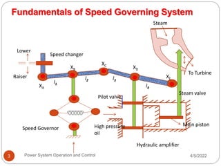
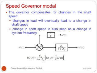
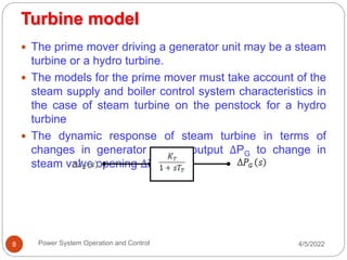
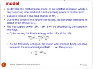
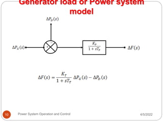
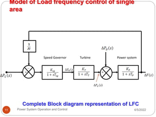
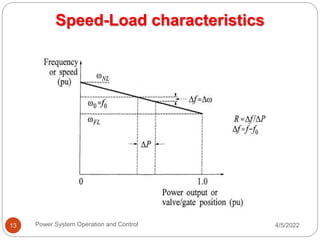
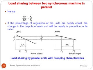
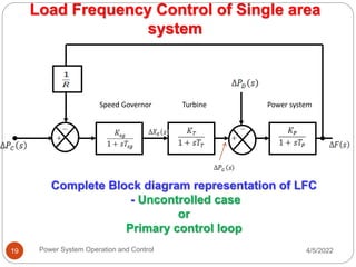
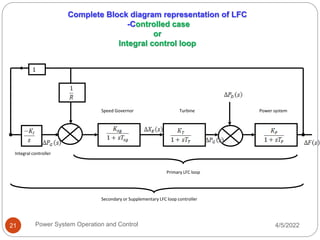
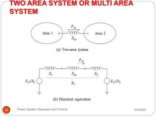
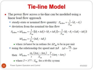
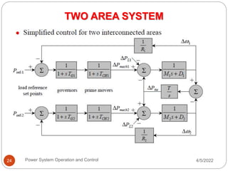
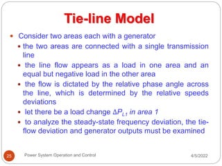
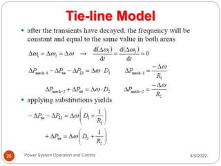
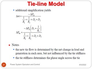
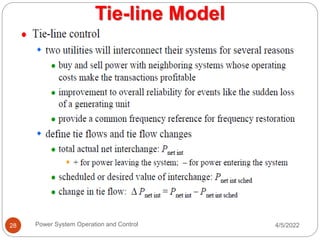
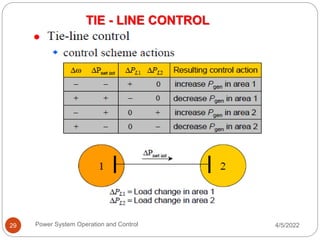
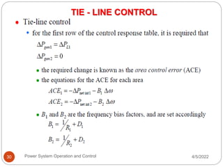
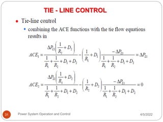
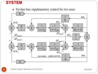
CALL ON ➥8923113531 🔝Call Girls Aminabad Lucknow best Night Fun service
Unit 2-1
1. REAL POWER- FREQUENCY CONTROL
Dr.R.Muthukumar, ASP /EEE
4/5/2022
Power System Operation and Control
1
2. Basics of speed governing mechanism
and modeling - speed-load
characteristics – load sharing between
two synchronous machines in parallel -
control area concept - LFC control of a
single-area system - static and dynamic
analysis of uncontrolled and controlled
cases - two-area system – modeling -
static analysis of uncontrolled case - tie
line with frequency bias control - state
variable model - integration of economic
dispatch control with LFC. 4/5/2022
Power System Operation and Control
2
4. Fundamentals of Speed Governing System
4/5/2022
Power System Operation and Control
4
The system consists of following
components
Fly ball governor
Hydraulic amplifier
Linkage mechanism
Speed changer
5. 4/5/2022
Power System Operation and Control
5
• Fly ball speed governor:
– This is the heart of the system which senses the
change in speed(frequency).
– As the speed increases the fly ball move outwards and
the point B on linkage mechanism moves downwards.
The reverse happens when the speed decreases.
• Hydraulic amplifier:
– It consists of pilot value and main piston.
– Low power level pilot value movement is converted into
high power level pilot value.
– This is necessary in order to open or close the steam
value against high pressure system.
Fundamentals of Speed Governing System
6. 4/5/2022
Power System Operation and Control
6
• Linkage mechanism:
– A,B,C is a rigid link pivoted at CDE in another rigid
kink pivoted at D.
– This link mechanism provides a movement to control
value in proportion to the change in speed.
• Speed Changer:
– It provides a steady state power output setting for the
turbine.
– Its downward movement opens the upper pilot value
so that more steam is admitted to the turbine under
steady state condition.
– The reverse happens for upward movement of speed
changer.
Fundamentals of Speed Governing System
7. Speed Governor modal
4/5/2022
Power System Operation and Control
7
The governor compensates for changes in the shaft
speed
changes in load will eventually lead to a change in
shaft speed
change in shaft speed is also seen as a change in
system frequency
8. Turbine model
4/5/2022
Power System Operation and Control
8
The prime mover driving a generator unit may be a steam
turbine or a hydro turbine.
The models for the prime mover must take account of the
steam supply and boiler control system characteristics in
the case of steam turbine on the penstock for a hydro
turbine
The dynamic response of steam turbine in terms of
changes in generator power output ΔPG to change in
steam valve opening ΔXE
9. model
4/5/2022
Power System Operation and Control
9
To develop the mathematical model of an isolated generator, which is
only supplying local load and is not supplying power to another area,
Suppose there is a real load change of ΔPD .
Due to the action of the turbine controllers, the generator increases its
output by an amount ΔPG .
The net surplus power (ΔPG - ΔPD ) will be absorbed by the system in
two ways.
By increasing the kinetic energy in the rotor at the rate
As the frequency changes, the motor load changes being sensitive
to speed, the rate of change of load w.r.t frequency f
10. Generator load or Power system
model
4/5/2022
Power System Operation and Control
10
11. Model of Load frequency control of single
area
4/5/2022
Power System Operation and Control
11
Complete Block diagram representation of LFC
Speed Governor Turbine Power system
12. Speed-Load characteristics
4/5/2022
Power System Operation and Control
12
The isochronous governors cannot be used when there
are two or more units connected to the same system since
each generator would have to precisely the same speed
setting.
For stable load sharing between two or more units
operating in parallel, the governors are provided with a
characteristics so that the speed drops as the load in
increased.
Percent speed regulation or droop:
The value of R determine the steady state speed versus
load characteristics of generating unit. The ratio of
speed deviation(Δω) or frequency deviation (Δf) to
change in valve/gate position (ΔY) or power output (ΔP)
is equal to R.
14. 4/5/2022
Power System Operation and Control
14
The parameter R is referred to as speed
regulation or droop. It can be expressed in
percent as
Speed-Load characteristics
15. Load sharing between two synchronous machine in
parallel
4/5/2022
Power System Operation and Control
15
If two or more generators with drooping governor
characteristics are connected to a power system, there will
be a unique frequency at which they will share a load
change
They are initially at nominal frequency f0,with outputs P1 and
P2.
When a load increases ΔPL causes the units to slow down,
the governors increase output until they reach a new
common operating frequency f’.
The amount of load picked up by each unit depends on the
droop characteristics:
16. 4/5/2022
Power System Operation and Control
16
Hence
If the percentage of regulation of the units are nearly equal, the
change in the outputs of each unit will be nearly in proportion to its
rating
Load sharing between two synchronous machine in
parallel
Load sharing by parallel units with drooping characteristics
17. Control Area
4/5/2022
Power System Operation and Control
17
Definition
It is defined as a power system, a part of a system or
combination of systems to which a common generation
control scheme is applied.
The electrical interconnection within each control area
is very strong as compared to the ties with the
neighboring areas.
All the generators in a control area swing in coherently
or it is characterized by a single frequency
It is necessary to be considered as many control area
as number of coherent group.
18. 4/5/2022
Power System Operation and Control
18
AGC problem of a large interconnected power
system has been studied by dividing a whole
system into a number of control areas.
In normal steady state operation, each control
area of a power system should try to compensate
for those demand in power.
Simultaneously, each control area of a power
system should help to maintain the frequency and
voltage profile of the overall systems.
Control Area
19. Complete Block diagram representation of LFC
- Uncontrolled case
or
Primary control loop
Speed Governor Turbine Power system
Load Frequency Control of Single area
system
4/5/2022
Power System Operation and Control
19
21. Speed Governor Turbine Power system
Integral controller
Primary LFC loop
Secondary or Supplementary LFC loop controller
1
Complete Block diagram representation of LFC
-Controlled case
or
Integral control loop
4/5/2022
Power System Operation and Control
21
22. TWO AREA SYSTEM OR MULTI AREA
SYSTEM
4/5/2022
Power System Operation and Control
22
25. 4/5/2022
Power System Operation and Control
25
Consider two areas each with a generator
the two areas are connected with a single transmission
line
the line flow appears as a load in one area and an
equal but negative load in the other area
the flow is dictated by the relative phase angle across
the line, which is determined by the relative speeds
deviations
let there be a load change ΔPL1 in area 1
to analyze the steady-state frequency deviation, the tie-
flow deviation and generator outputs must be examined
Tie-line Model