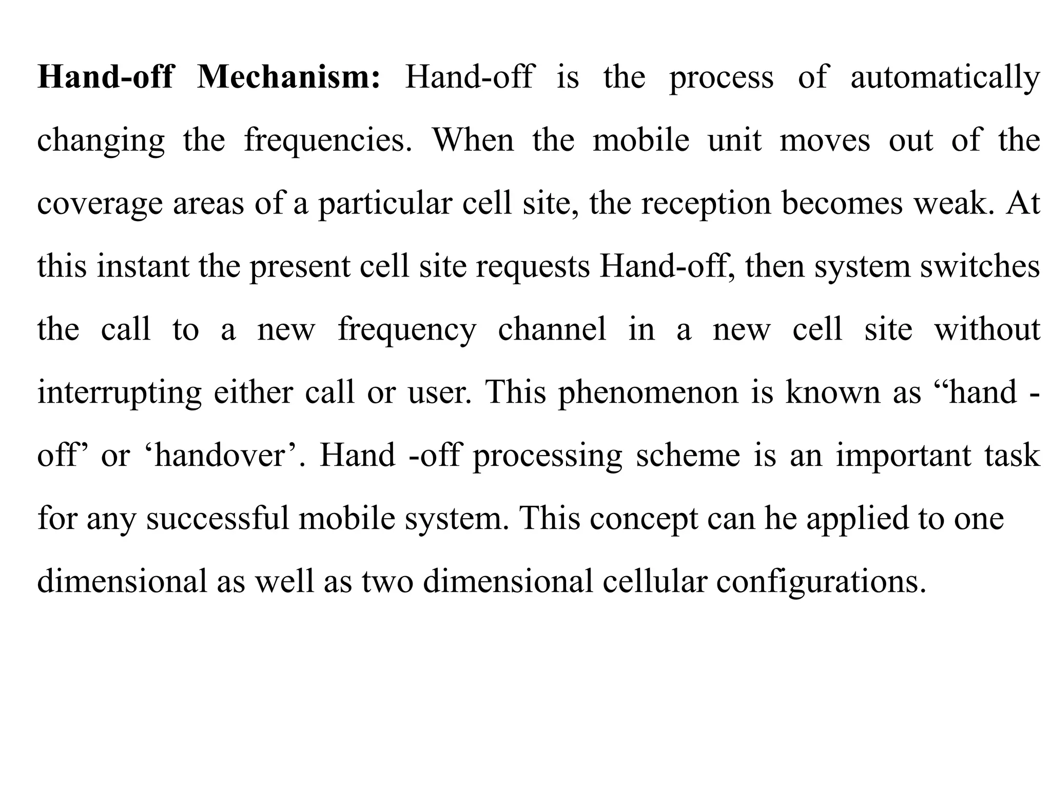
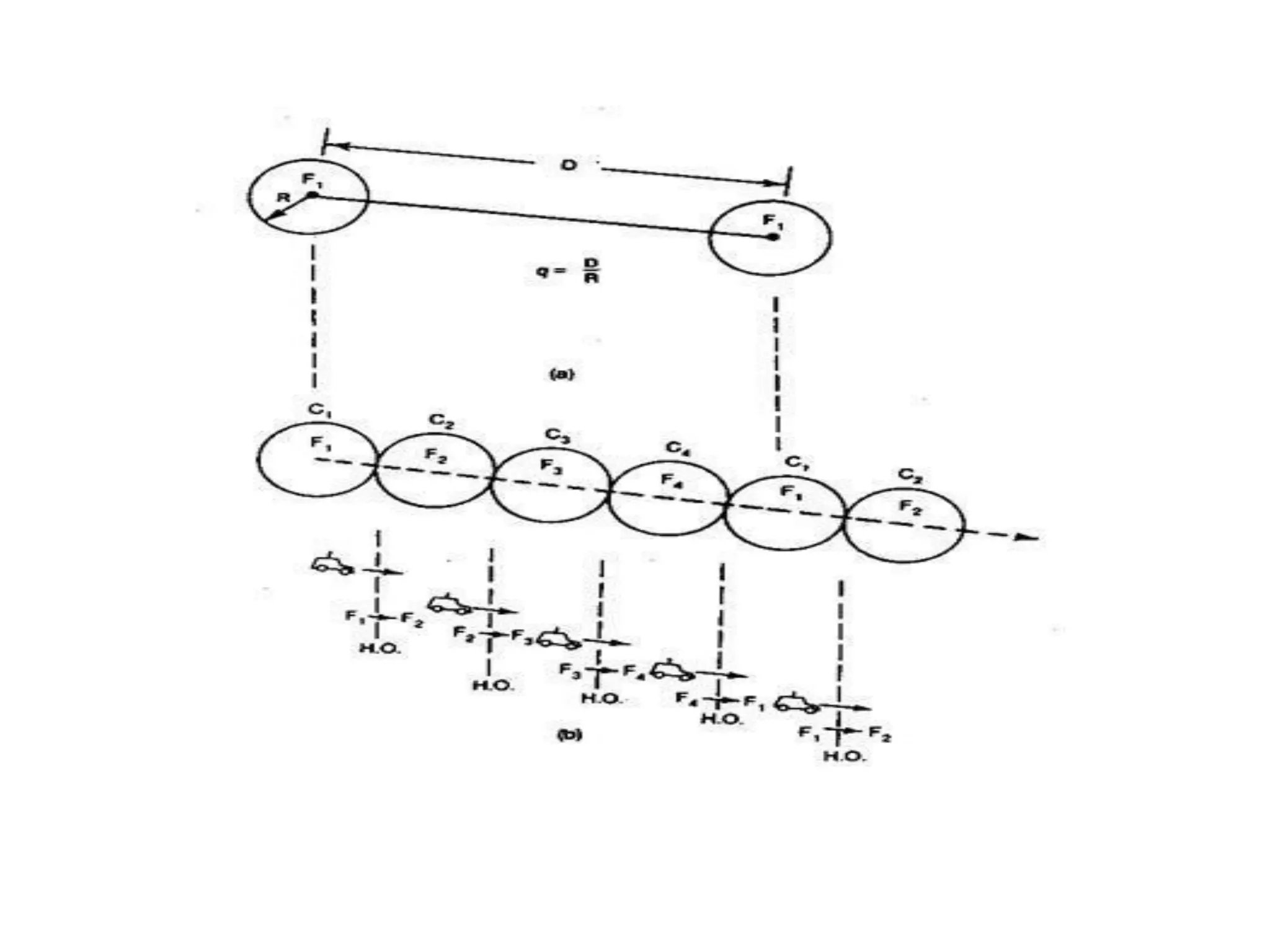
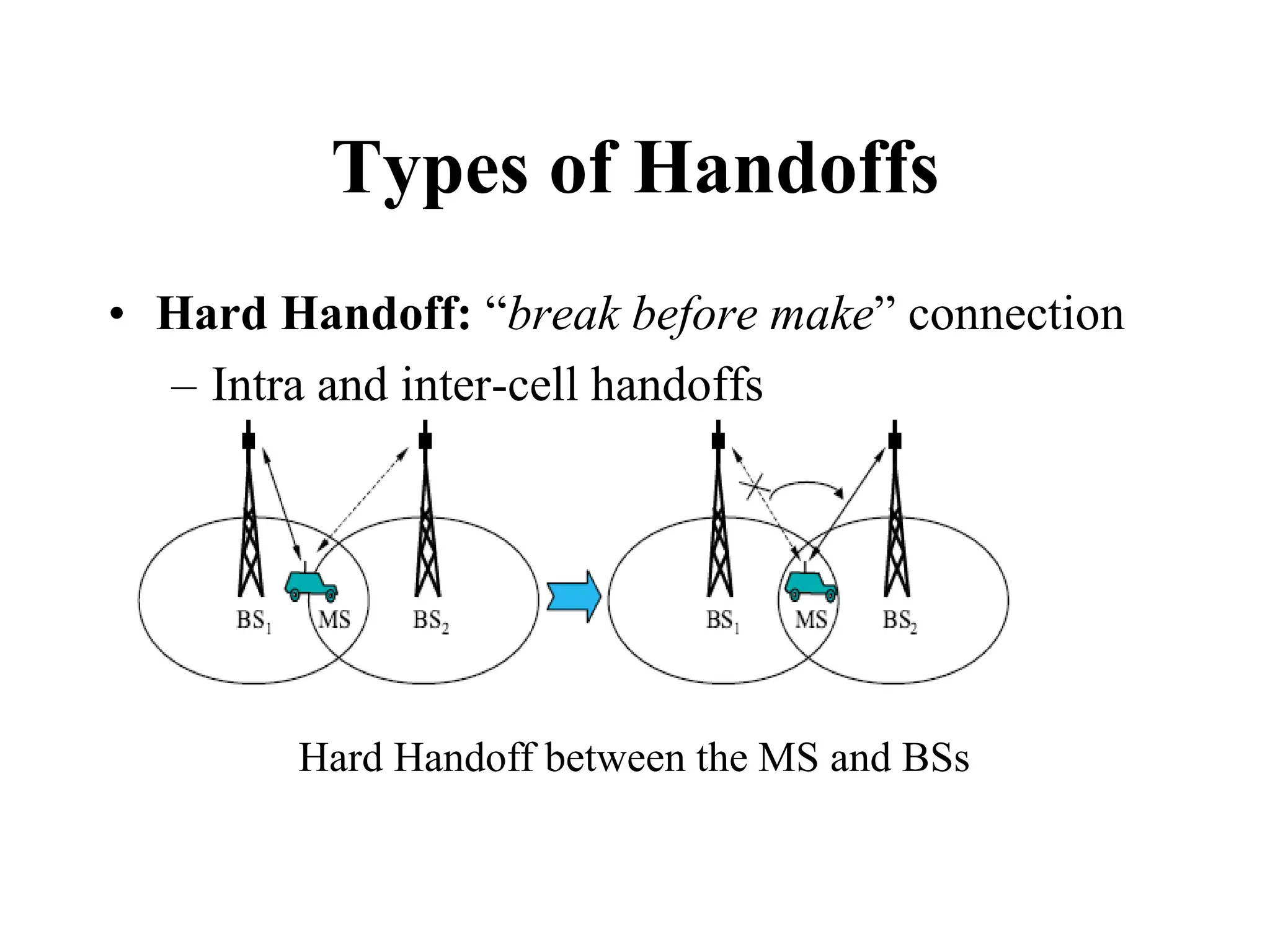
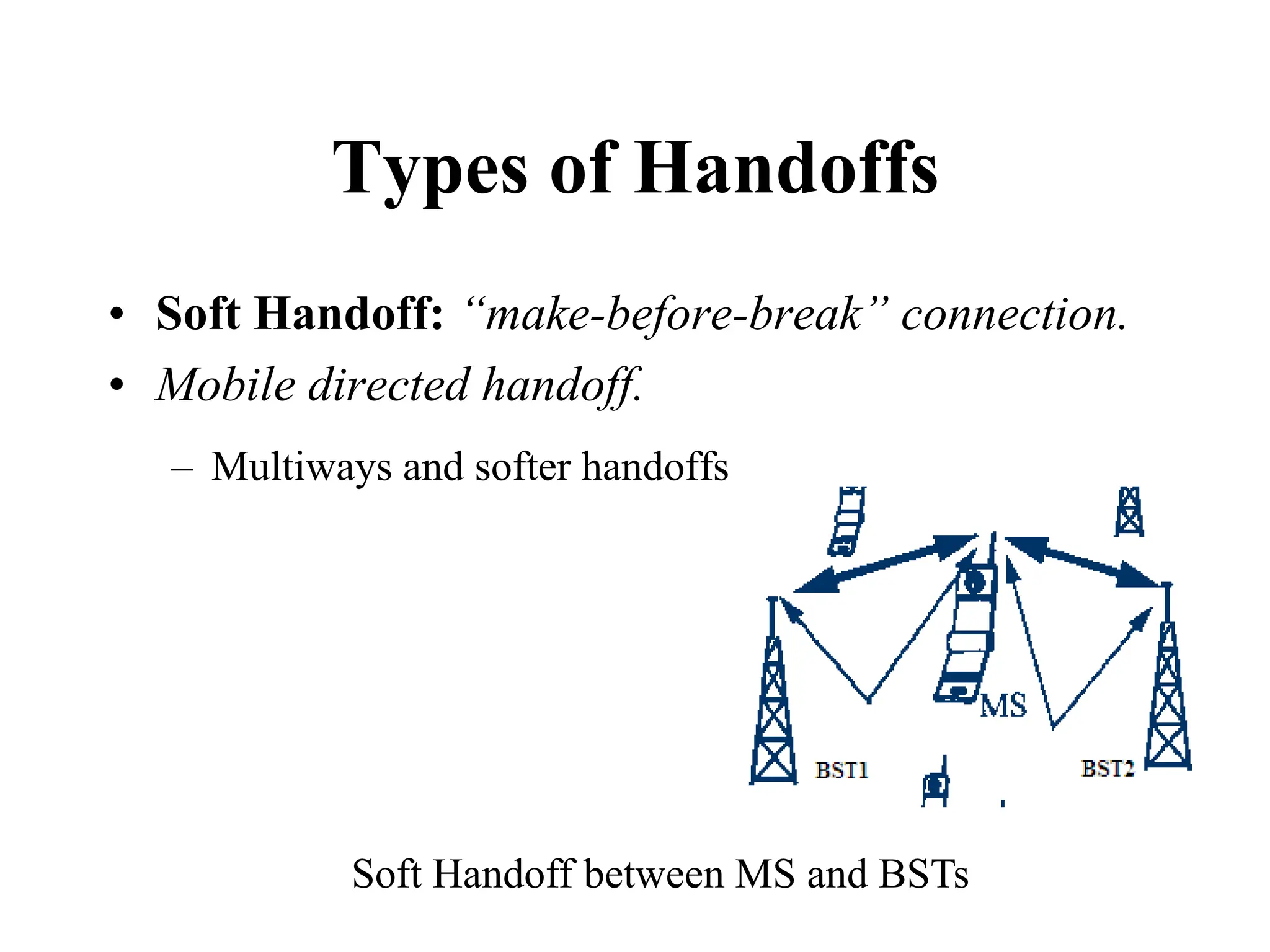
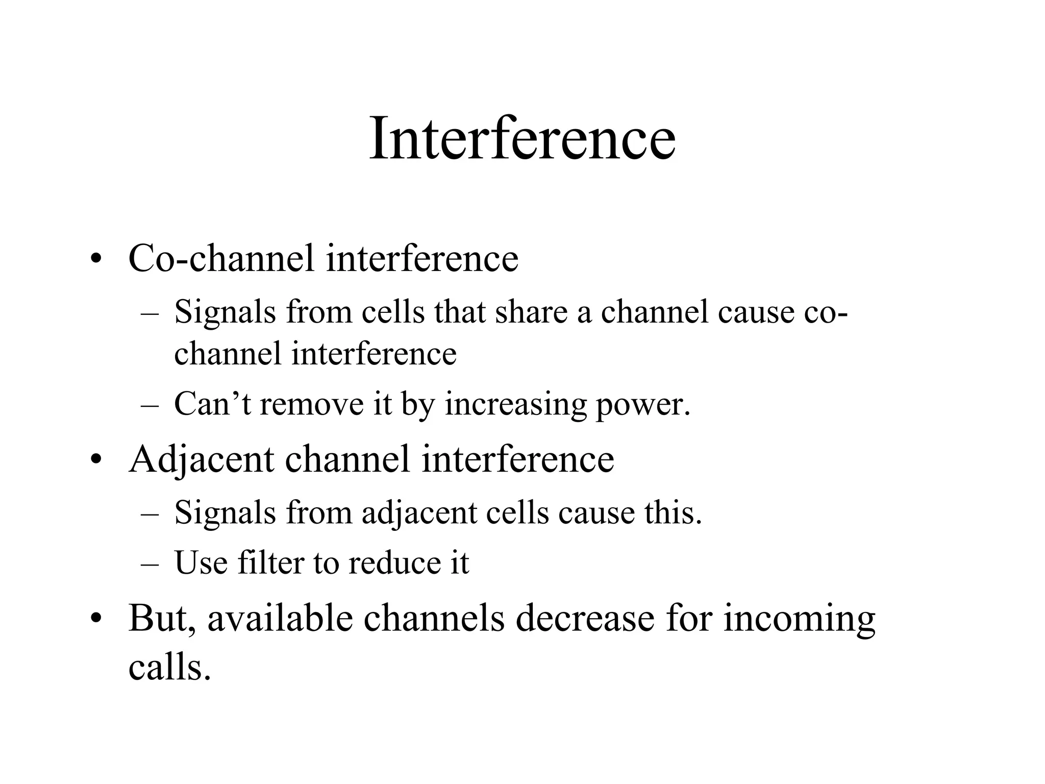
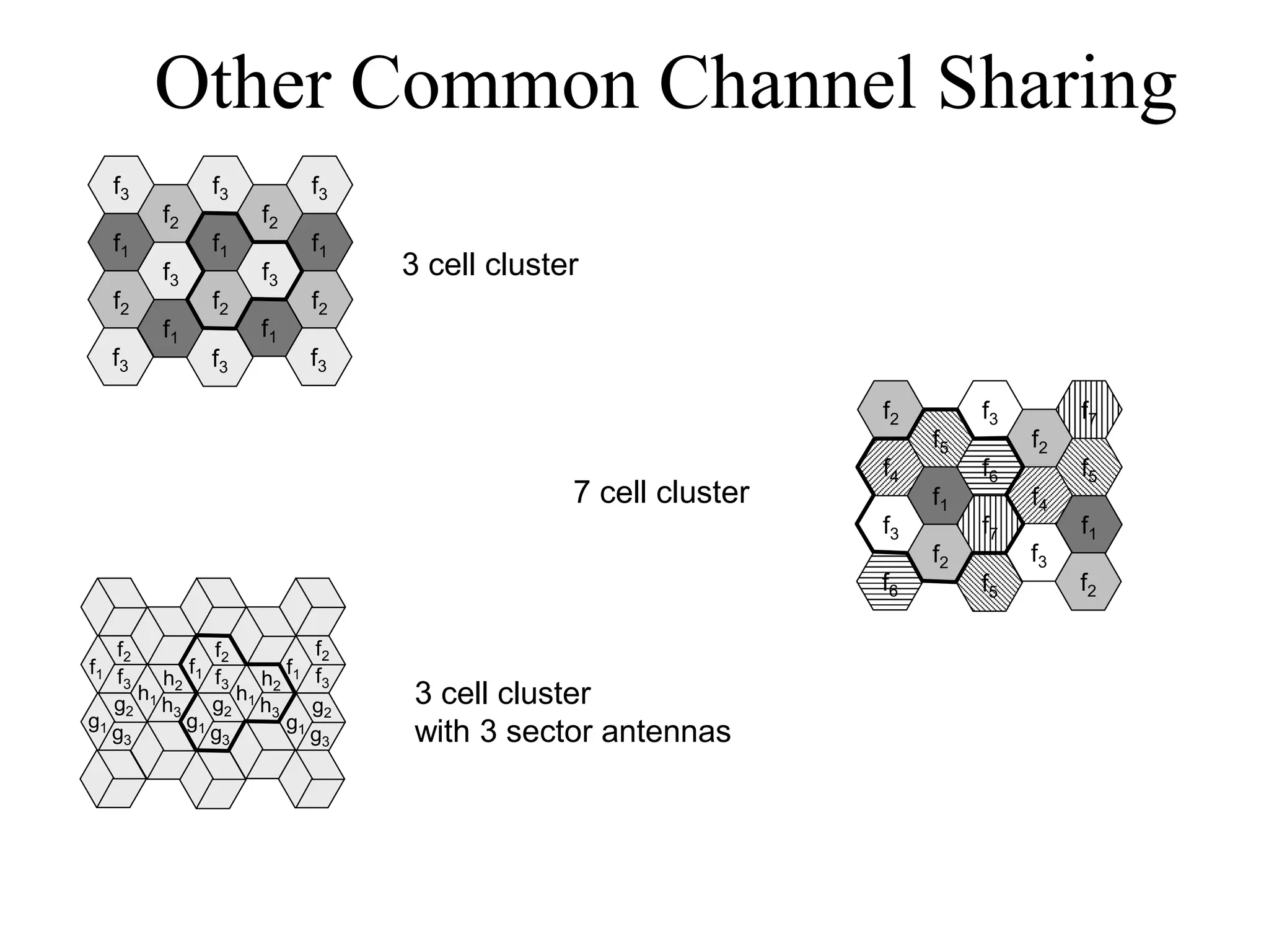
Chapter- Three
Elements of Cellular Radio
System Design
Based on the concept of efficient spectrum utilization, Elements of
Cellular Mobile Radio System Design can be broken down into
many elements. The major elements are:
• Low power transmitter system
• Increase network capacity
• Frequency reuse
• Co-channel Interference
• Handoff Mechanism
• Cell Splitting
Challenge to serve the greatest number of customers
with a specified system quality.
1. How many customers can be served in a busy hour?
2. How many subscribers can we take into the system?
3. How many frequency channels are needed?
Maximum Number of Calls per Hour per Cell
To calculate the predicted number of calls per hour per cell Q in each
cell, the following parameters are required
• The size of the cell
• The traffic conditions in the cell
Maximum number of frequency channels per cell
The maximum number of frequency channels per cell N is closely
related to an average calling time in the system. The standard user’s
calling habits may change as a result of the charging rate of the
system and the general income profile of the users If an average
calling time T is 1.76 min and the maximum calls per hour per cell is
Qi, then the offered load can be derived as
A = Qi*T/60 (Erlangs)
Idea!
• Partition the region into smaller regions
called cells.
• Each cell gets at least one base station or
tower
• Users within a cell talks to the tower
• How can we divide the region into cells?
“Cell”ular Structure
Properties of Cell structure
• Typical Cell sizes
– some cites few hundred meters
– country side few tens of kilometers
• Advantages of cell structures:
– more capacity due to frequency reusage
– less transmission power needed
– more robust, tolerate failures
– deals interference, transmission area locally
• Problems:
– fixed network needed for the base stations
– handover (changing from one cell to another) necessary
– interference with other cells
Concept of Frequency Reuse Channels: A radio channel consists of a pair of
frequencies one for each direction of transmission that is used for full-duplex
operation. Particular radio channels, say F1, used in one geographic zone to call
a cell, say C1, with a coverage radius R can be used in another cell with the
same coverage radius at a distance D away. Frequency reuse is the core concept
of the cellular mobile radio system. In this frequency reuse system users in
different geographic locations (different cells) may simultaneously use the same
frequency channel (see Fig.2.1). The frequency reuse system can drastically
increase the spectrum efficiency, but if the system is not properly designed,
serious interference may occur. Interference due to the common use of the same
channel is called co-channel interference and is our major concern in the
concept of frequency reuse.
Frequency reuse scheme: The frequency reuse concept can be used in
the time domain and the space domain. Frequency reuse in the time domain
results in the occupation of the same frequency in different time slots. It is
called time division multiplexing (TDM). Frequency reuse in the space
domain can be divided into two categories.
1. Same frequency assigned in two different geographic areas, such as
A.M or FM radio stations using the same frequency in different cities.
2. Same frequency repeatedly used in a same general area in one system -
the scheme is used in cellular systems. There are many co-channel cells
in the system. The total frequency spectrum allocation is divided into K
frequency reuse patterns, as illustrated in Fig. 2.2 for K — 4, 7, 12, and
19.
Cochannel Interference Reduction Factor:
Reusing an identical frequency channel in different cells is limited by
cochannel interference between cells, and the cochannel interference
can become a major problem.
Assume that the size of all cells is roughly the same. The cell size is
determined by the coverage area of the signal strength in each cell. As
long as the cell size is fixed, cochannel interference is independent of
the transmitted power of each cell. It means that the received threshold
level at the mobile unit is adjusted to the size of the cell. Actually,
cochannel interference is a function of a parameter q defined as
q = D/R
The parameter q is the cochannel interference reduction factor. When
the ratio q increases, cochannel interference decreases. Furthermore, the
separation D is a function of K, and C/I,
D=f(K,C/I)
Where K, is the number of cochannel interfering cells in the first tier
and C/I is the received carrier-to-interference ratio at the desired mobile
receiver.
According to both the reciprocity theorem and the statistical
summation of radio propagation, the two C/I values can be very
close. Assume that the local noise is much less than the interference
level and can be neglected. C/I then can be expressed as
The six cochannel interfering cells in the second tier cause weaker
interference than those in the first tier. Therefore, the cochannel
interference from the second tier of interfering cells is negligible
Where qk is the cochannel interference reduction factor with Kth
cochannel interfering cell
Hand-off Mechanism: Hand-off is the process of automatically
changing the frequencies. When the mobile unit moves out of the
coverage areas of a particular cell site, the reception becomes weak. At
this instant the present cell site requests Hand-off, then system switches
the call to a new frequency channel in a new cell site without
interrupting either call or user. This phenomenon is known as “hand -
off’ or ‘handover’. Hand -off processing scheme is an important task
for any successful mobile system. This concept can he applied to one
dimensional as well as two dimensional cellular configurations.
Types of Handoffs
• Hard Handoff: “break before make” connection
– Intra and inter-cell handoffs
Hard Handoff between the MS and BSs
Types of Handoffs
• Soft Handoff: “make-before-break” connection.
• Mobile directed handoff.
– Multiways and softer handoffs
Soft Handoff between MS and BSTs
Cell Splitting
There are two kinds of cell-splitting techniques:
Permanent splitting: The installation of every new split cell has to be
planned ahead of time; the number of channels, the transmitted power,
the assigned frequencies, the choosing of the cell-site selection, and the
traffic load consideration should all be considered. When ready, the
actual service cut-over should be set at the lowest traffic point, usually at
midnight on a weekend. Hopefully, only a few calls will be dropped
because of this cut-over, assuming that the downtime of the system is
within 2 h.
Dynamic splitting: This scheme is based on using the allocated
spectrum efficiency in real time. The algorithm for dynamically splitting
cell sites is a tedious job, as we cannot afford to have one single cell
unused during cell splitting at heavy traffic hours.
Interference
• Co-channel interference
– Signals from cells that share a channel cause co-
channel interference
– Can’t remove it by increasing power.
• Adjacent channel interference
– Signals from adjacent cells cause this.
– Use filter to reduce it
• But, available channels decrease for incoming
calls.
Other Common Channel Sharing
f1
f2
f3
f2
f1
f1
f2
f3
f2
f3
f1
f2
f1
f3
f3
f3
f3
f3
f4
f5
f1
f3
f2
f6
f7
f3
f2
f4
f5
f1
f3
f5
f6
f7
f2
f2
f1
f1 f1
f2
f3
f2
f3
f2
f3
h1
h2
h3
g1
g2
g3
h1
h2
h3
g1
g2
g3
g1
g2
g3
3 cell cluster
7 cell cluster
3 cell cluster
with 3 sector antennas

03. Chapter- Three Elements of Cellular Radio System Design1.pdf

  • 1.
    Chapter- Three Elements ofCellular Radio System Design
  • 2.
    Based on theconcept of efficient spectrum utilization, Elements of Cellular Mobile Radio System Design can be broken down into many elements. The major elements are: • Low power transmitter system • Increase network capacity • Frequency reuse • Co-channel Interference • Handoff Mechanism • Cell Splitting
  • 3.
    Challenge to servethe greatest number of customers with a specified system quality. 1. How many customers can be served in a busy hour? 2. How many subscribers can we take into the system? 3. How many frequency channels are needed?
  • 4.
    Maximum Number ofCalls per Hour per Cell To calculate the predicted number of calls per hour per cell Q in each cell, the following parameters are required • The size of the cell • The traffic conditions in the cell Maximum number of frequency channels per cell The maximum number of frequency channels per cell N is closely related to an average calling time in the system. The standard user’s calling habits may change as a result of the charging rate of the system and the general income profile of the users If an average calling time T is 1.76 min and the maximum calls per hour per cell is Qi, then the offered load can be derived as A = Qi*T/60 (Erlangs)
  • 5.
    Idea! • Partition theregion into smaller regions called cells. • Each cell gets at least one base station or tower • Users within a cell talks to the tower • How can we divide the region into cells?
  • 6.
  • 7.
    Properties of Cellstructure • Typical Cell sizes – some cites few hundred meters – country side few tens of kilometers • Advantages of cell structures: – more capacity due to frequency reusage – less transmission power needed – more robust, tolerate failures – deals interference, transmission area locally • Problems: – fixed network needed for the base stations – handover (changing from one cell to another) necessary – interference with other cells
  • 8.
    Concept of FrequencyReuse Channels: A radio channel consists of a pair of frequencies one for each direction of transmission that is used for full-duplex operation. Particular radio channels, say F1, used in one geographic zone to call a cell, say C1, with a coverage radius R can be used in another cell with the same coverage radius at a distance D away. Frequency reuse is the core concept of the cellular mobile radio system. In this frequency reuse system users in different geographic locations (different cells) may simultaneously use the same frequency channel (see Fig.2.1). The frequency reuse system can drastically increase the spectrum efficiency, but if the system is not properly designed, serious interference may occur. Interference due to the common use of the same channel is called co-channel interference and is our major concern in the concept of frequency reuse.
  • 10.
    Frequency reuse scheme:The frequency reuse concept can be used in the time domain and the space domain. Frequency reuse in the time domain results in the occupation of the same frequency in different time slots. It is called time division multiplexing (TDM). Frequency reuse in the space domain can be divided into two categories. 1. Same frequency assigned in two different geographic areas, such as A.M or FM radio stations using the same frequency in different cities. 2. Same frequency repeatedly used in a same general area in one system - the scheme is used in cellular systems. There are many co-channel cells in the system. The total frequency spectrum allocation is divided into K frequency reuse patterns, as illustrated in Fig. 2.2 for K — 4, 7, 12, and 19.
  • 12.
    Cochannel Interference ReductionFactor: Reusing an identical frequency channel in different cells is limited by cochannel interference between cells, and the cochannel interference can become a major problem. Assume that the size of all cells is roughly the same. The cell size is determined by the coverage area of the signal strength in each cell. As long as the cell size is fixed, cochannel interference is independent of the transmitted power of each cell. It means that the received threshold level at the mobile unit is adjusted to the size of the cell. Actually, cochannel interference is a function of a parameter q defined as q = D/R
  • 14.
    The parameter qis the cochannel interference reduction factor. When the ratio q increases, cochannel interference decreases. Furthermore, the separation D is a function of K, and C/I, D=f(K,C/I) Where K, is the number of cochannel interfering cells in the first tier and C/I is the received carrier-to-interference ratio at the desired mobile receiver.
  • 15.
    According to boththe reciprocity theorem and the statistical summation of radio propagation, the two C/I values can be very close. Assume that the local noise is much less than the interference level and can be neglected. C/I then can be expressed as
  • 16.
    The six cochannelinterfering cells in the second tier cause weaker interference than those in the first tier. Therefore, the cochannel interference from the second tier of interfering cells is negligible Where qk is the cochannel interference reduction factor with Kth cochannel interfering cell
  • 17.
    Hand-off Mechanism: Hand-offis the process of automatically changing the frequencies. When the mobile unit moves out of the coverage areas of a particular cell site, the reception becomes weak. At this instant the present cell site requests Hand-off, then system switches the call to a new frequency channel in a new cell site without interrupting either call or user. This phenomenon is known as “hand - off’ or ‘handover’. Hand -off processing scheme is an important task for any successful mobile system. This concept can he applied to one dimensional as well as two dimensional cellular configurations.
  • 19.
    Types of Handoffs •Hard Handoff: “break before make” connection – Intra and inter-cell handoffs Hard Handoff between the MS and BSs
  • 20.
    Types of Handoffs •Soft Handoff: “make-before-break” connection. • Mobile directed handoff. – Multiways and softer handoffs Soft Handoff between MS and BSTs
  • 21.
    Cell Splitting There aretwo kinds of cell-splitting techniques: Permanent splitting: The installation of every new split cell has to be planned ahead of time; the number of channels, the transmitted power, the assigned frequencies, the choosing of the cell-site selection, and the traffic load consideration should all be considered. When ready, the actual service cut-over should be set at the lowest traffic point, usually at midnight on a weekend. Hopefully, only a few calls will be dropped because of this cut-over, assuming that the downtime of the system is within 2 h. Dynamic splitting: This scheme is based on using the allocated spectrum efficiency in real time. The algorithm for dynamically splitting cell sites is a tedious job, as we cannot afford to have one single cell unused during cell splitting at heavy traffic hours.
  • 23.
    Interference • Co-channel interference –Signals from cells that share a channel cause co- channel interference – Can’t remove it by increasing power. • Adjacent channel interference – Signals from adjacent cells cause this. – Use filter to reduce it • But, available channels decrease for incoming calls.
  • 24.
    Other Common ChannelSharing f1 f2 f3 f2 f1 f1 f2 f3 f2 f3 f1 f2 f1 f3 f3 f3 f3 f3 f4 f5 f1 f3 f2 f6 f7 f3 f2 f4 f5 f1 f3 f5 f6 f7 f2 f2 f1 f1 f1 f2 f3 f2 f3 f2 f3 h1 h2 h3 g1 g2 g3 h1 h2 h3 g1 g2 g3 g1 g2 g3 3 cell cluster 7 cell cluster 3 cell cluster with 3 sector antennas