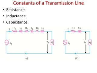
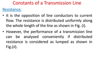
1. The document discusses transmission line parameters and types of transmission lines. It covers resistance, inductance, capacitance and other constants of transmission lines.
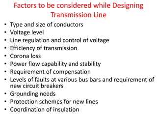
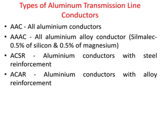
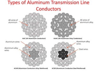
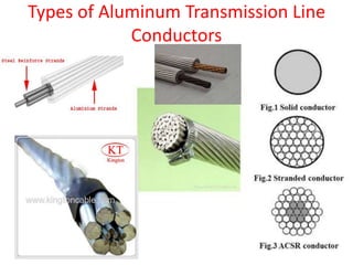
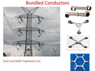
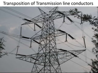
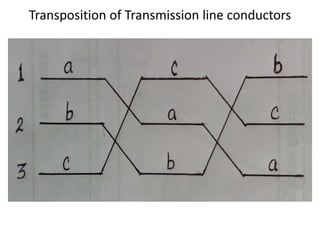
2. Different types of conductors used for transmission lines like ACSR, AAAC, and bundled conductors are described. Factors to consider while designing transmission lines are also outlined.
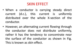
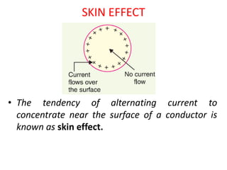
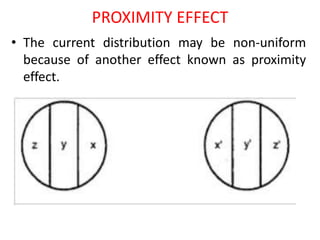
3. Skin effect and proximity effect, which cause non-uniform current distribution in conductors, are explained. Both effects increase resistance and depend on frequency, diameter, and spacing of conductors.